JP2007265270A - Storage system and storage area allocation method - Google Patents
Storage system and storage area allocation methodDownload PDFInfo
- Publication number
- JP2007265270A JP2007265270AJP2006092236AJP2006092236AJP2007265270AJP 2007265270 AJP2007265270 AJP 2007265270AJP 2006092236 AJP2006092236 AJP 2006092236AJP 2006092236 AJP2006092236 AJP 2006092236AJP 2007265270 AJP2007265270 AJP 2007265270A
- Authority
- JP
- Japan
- Prior art keywords
- logical volume
- data
- pool
- virtual logical
- storage area
- Prior art date
- Legal status (The legal status is an assumption and is not a legal conclusion. Google has not performed a legal analysis and makes no representation as to the accuracy of the status listed.)
- Pending
Links
Images


Classifications
- G—PHYSICS
- G06—COMPUTING OR CALCULATING; COUNTING
- G06F—ELECTRIC DIGITAL DATA PROCESSING
- G06F12/00—Accessing, addressing or allocating within memory systems or architectures
- G06F12/02—Addressing or allocation; Relocation
- G06F12/0223—User address space allocation, e.g. contiguous or non contiguous base addressing
- G06F12/023—Free address space management
- G—PHYSICS
- G06—COMPUTING OR CALCULATING; COUNTING
- G06F—ELECTRIC DIGITAL DATA PROCESSING
- G06F3/00—Input arrangements for transferring data to be processed into a form capable of being handled by the computer; Output arrangements for transferring data from processing unit to output unit, e.g. interface arrangements
- G06F3/06—Digital input from, or digital output to, record carriers, e.g. RAID, emulated record carriers or networked record carriers
- G06F3/0601—Interfaces specially adapted for storage systems
- G06F3/0602—Interfaces specially adapted for storage systems specifically adapted to achieve a particular effect
- G06F3/0608—Saving storage space on storage systems
- G—PHYSICS
- G06—COMPUTING OR CALCULATING; COUNTING
- G06F—ELECTRIC DIGITAL DATA PROCESSING
- G06F3/00—Input arrangements for transferring data to be processed into a form capable of being handled by the computer; Output arrangements for transferring data from processing unit to output unit, e.g. interface arrangements
- G06F3/06—Digital input from, or digital output to, record carriers, e.g. RAID, emulated record carriers or networked record carriers
- G06F3/0601—Interfaces specially adapted for storage systems
- G06F3/0628—Interfaces specially adapted for storage systems making use of a particular technique
- G06F3/0629—Configuration or reconfiguration of storage systems
- G06F3/0631—Configuration or reconfiguration of storage systems by allocating resources to storage systems
- G—PHYSICS
- G06—COMPUTING OR CALCULATING; COUNTING
- G06F—ELECTRIC DIGITAL DATA PROCESSING
- G06F3/00—Input arrangements for transferring data to be processed into a form capable of being handled by the computer; Output arrangements for transferring data from processing unit to output unit, e.g. interface arrangements
- G06F3/06—Digital input from, or digital output to, record carriers, e.g. RAID, emulated record carriers or networked record carriers
- G06F3/0601—Interfaces specially adapted for storage systems
- G06F3/0628—Interfaces specially adapted for storage systems making use of a particular technique
- G06F3/0638—Organizing or formatting or addressing of data
- G06F3/0644—Management of space entities, e.g. partitions, extents, pools
- G—PHYSICS
- G06—COMPUTING OR CALCULATING; COUNTING
- G06F—ELECTRIC DIGITAL DATA PROCESSING
- G06F3/00—Input arrangements for transferring data to be processed into a form capable of being handled by the computer; Output arrangements for transferring data from processing unit to output unit, e.g. interface arrangements
- G06F3/06—Digital input from, or digital output to, record carriers, e.g. RAID, emulated record carriers or networked record carriers
- G06F3/0601—Interfaces specially adapted for storage systems
- G06F3/0668—Interfaces specially adapted for storage systems adopting a particular infrastructure
- G06F3/067—Distributed or networked storage systems, e.g. storage area networks [SAN], network attached storage [NAS]
Landscapes
- Engineering & Computer Science (AREA)
- Theoretical Computer Science (AREA)
- Physics & Mathematics (AREA)
- General Engineering & Computer Science (AREA)
- General Physics & Mathematics (AREA)
- Human Computer Interaction (AREA)
- Information Retrieval, Db Structures And Fs Structures Therefor (AREA)
- Memory System Of A Hierarchy Structure (AREA)
Abstract
Description
Translated fromJapanese本発明は、記憶領域が動的に割り当てられ、ホスト計算機に提供される仮想論理ボリュームを有するストレージシステムに適用して好適なものである。 The present invention is suitable for application to a storage system in which a storage area is dynamically allocated and has a virtual logical volume provided to a host computer.
近年、データを格納するための記憶領域をホスト計算機に提供するストレージシステムでは、非常に数多くの大容量ディスクデバイスを備えることが可能となり、記憶容量の大規模化が進んでいる。このようなストレージシステムでは、まずディスクデバイスから、RAID(Redundant Array of Independent Disks)構成されたディスクアレイを作成し、この物理的な記憶リソースを複数個集めて、物理論理ボリュームを作成しておき、その物理論理ボリュームからホスト計算機が要求する容量の記憶領域を論理ボリュームとして作成し、ホスト計算機に提供する。 In recent years, a storage system that provides a storage area for storing data to a host computer can include a large number of large-capacity disk devices, and the storage capacity has been increasing in scale. In such a storage system, first, a disk array having a RAID (Redundant Array of Independent Disks) configuration is created from disk devices, and a plurality of physical storage resources are collected to create a physical logical volume. A storage area having a capacity required by the host computer is created as a logical volume from the physical logical volume and provided to the host computer.
さらに近年では、物理論理ボリュームから固定容量の論理ボリュームを作成せずに、まずホスト計算機に仮想的な論理ボリューム(以下、仮想論理ボリュームと呼ぶ)を提供し、ホスト計算機からのコマンドに応じて、その仮想論理ボリュームに対して、ある単位で記憶領域を、物理リソースである物理論理ボリュームから動的に割り当てることで動的に記憶容量を拡張するストレージシステムが提案されている。 Furthermore, in recent years, without creating a fixed-capacity logical volume from a physical logical volume, a virtual logical volume (hereinafter referred to as a virtual logical volume) is first provided to the host computer, and in response to a command from the host computer, There has been proposed a storage system that dynamically expands the storage capacity by dynamically allocating a storage area to the virtual logical volume from a physical logical volume that is a physical resource.
例えば、特許文献1のストレージシステムでは、複数のディスク記憶装置から個々のホスト計算機に対応する仮想論理ボリュームを提供し、ホスト計算機から送信された仮想論理ボリュームへのコマンドにより、読み出しや書き込みが行われる論理ブロックアドレスを読み取り、仮想論理ボリューム上にコマンドがアクセスした論理ブロックアドレスの記憶領域が存在しない場合、ボリューム提供装置が未使用磁気ディスク記憶装置から記憶領域を割り当て、動的に仮想論理ボリュームの記憶領域を拡張するようになされている。
しかしながら、特許文献1のストレージシステムでは、予め固定された割当てサイズで仮想論理ボリュームに記憶領域を割り当てるようになされているため、ホスト装置から送信されるデータに対して、当該データを格納する記憶領域の割当てサイズが大きい割当てサイズで固定されている場合には、ホスト計算機から小さいサイズのデータが送信されたときにも、大きい割当てサイズで記憶領域が割り当てられることとなり、記憶領域の運用効率が悪いという問題がある。 However, in the storage system of
一方、特許文献1のストレージシステムでは、ホスト装置から送信されるデータに対して、当該データを格納する記憶領域の割当てサイズが小さい割当てサイズで固定されている場合には、割り当てた記憶領域を管理するための管理ビット数を増加させなければならず、当該管理ビットを保持するために、膨大なメモリ容量が必要となることとなる。 On the other hand, in the storage system of
本発明は以上の点を考慮してなされたもので、記憶領域の運用効率を格段的に向上させ得るストレージシステム及び記憶領域割当て方法を提案するものである。 The present invention has been made in consideration of the above points, and proposes a storage system and a storage area allocation method capable of dramatically improving the storage area operational efficiency.
かかる課題を解決するために本発明においては、ホスト計算機から送信されるデータを格納するための記憶領域と、当該記憶領域が動的に割り当てられ、ホスト計算機に提供される仮想論理ボリュームとを有するストレージシステムにおいて、記憶領域により構成されるプール領域を複数作成するプール領域作成部と、プール領域内の記憶領域を仮想論理ボリュームに割り当てる際の、当該記憶領域の割当てサイズを、プール領域作成部により作成された複数のプール領域ごとに設定する設定部と、ホスト計算機から記憶領域に格納すべきデータが送信されたときに、当該データのデータサイズに応じて、設定部により設定されたいずれかのプール領域を選択する選択部と、選択部により選択されたプール領域の記憶領域を仮想論理ボリュームに割り当てる割当て部とを備えるようにした。 In order to solve this problem, the present invention has a storage area for storing data transmitted from the host computer, and a virtual logical volume to which the storage area is dynamically allocated and provided to the host computer. In a storage system, a pool area creation unit that creates a plurality of pool areas composed of storage areas, and an allocation size of the storage area when a storage area in the pool area is assigned to a virtual logical volume is determined by the pool area creation unit. When the data to be stored in the storage area is sent from the host computer to the setting section that is set for each of the created pool areas, one of the settings that is set by the setting section according to the data size of the data A selection unit that selects a pool area and a storage area of the pool area selected by the selection unit are virtual logical volumes. And to and an allocation unit for allocating a.
従って、ホスト計算機から送信されるデータに対して、大きすぎる割当てサイズの記憶領域や、小さすぎる割当てサイズの記憶領域を複数割り当てることを有効に防止し、当該データに対して、適切な割当てサイズの記憶領域を割り当てることができる。 Therefore, it is possible to effectively prevent the allocation of a storage area with an allocation size that is too large or a storage area with an allocation size that is too small for the data transmitted from the host computer. A storage area can be allocated.
また、本発明においては、ホスト計算機から送信されるデータを格納するための記憶領域と、当該記憶領域が動的に割り当てられ、ホスト計算機に提供される仮想論理ボリュームとを有するストレージシステムの記憶領域割当て方法において、記憶領域により構成されるプール領域を複数作成する第1のステップと、プール領域内の記憶領域を仮想論理ボリュームに割り当てる際の、当該記憶領域の割当てサイズを、第1のステップにおいて作成した複数のプール領域ごとに設定する第2のステップと、ホスト計算機から記憶領域に格納すべきデータが送信されたときに、当該データのデータサイズに応じて、第2のステップにおいて設定したいずれかの前記プール領域を選択する第3のステップと、第3のステップにおいて選択したプール領域の記憶領域を仮想論理ボリュームに割り当てる第4のステップとを備えるようにした。 In the present invention, a storage area of a storage system having a storage area for storing data transmitted from the host computer and a virtual logical volume to which the storage area is dynamically allocated and provided to the host computer In the allocation method, a first step of creating a plurality of pool areas constituted by storage areas, and an allocation size of the storage areas when allocating storage areas in the pool areas to virtual logical volumes are as follows: A second step that is set for each of the created pool areas, and any data set in the second step according to the data size of the data when data to be stored in the storage area is transmitted from the host computer. A third step of selecting the pool area, and the pool selected in the third step And so and a fourth step of allocating a storage area of the range to a virtual logical volume.
従って、ホスト計算機から送信されるデータに対して、大きすぎる割当てサイズの記憶領域や、小さすぎる割当てサイズの記憶領域を複数割り当てることを有効に防止し、当該データに対して、適切な割当てサイズの記憶領域を割り当てることができる。 Therefore, it is possible to effectively prevent the allocation of a storage area with an allocation size that is too large or a storage area with an allocation size that is too small for the data transmitted from the host computer. A storage area can be allocated.
本発明によれば、記憶領域により構成されるプール領域を複数作成し、プール領域内の記憶領域を仮想論理ボリュームに割り当てる際の、当該記憶領域の割当てサイズを、複数のプール領域ごとに設定して、ホスト計算機から記憶領域に格納すべきデータが送信されたときに、当該データのデータサイズに応じて、いずれかのプール領域を選択し、当該プール領域の記憶領域を仮想論理ボリュームに割り当てることにより、ホスト計算機から送信されるデータに対して、大きすぎる割当てサイズの記憶領域や、小さすぎる割当てサイズの記憶領域を複数割り当てることを有効に防止し、当該データに対して、適切な割当てサイズの記憶領域を割り当てることができ、かくして記憶領域の運用効率を格段的に向上させ得るストレージシステム及び記憶領域割当て方法を実現できる。 According to the present invention, when a plurality of pool areas configured by storage areas are created and the storage areas in the pool area are allocated to virtual logical volumes, the allocation size of the storage areas is set for each of the plurality of pool areas. When data to be stored in the storage area is transmitted from the host computer, one of the pool areas is selected according to the data size of the data, and the storage area of the pool area is allocated to the virtual logical volume. Therefore, it is possible to effectively prevent allocation of a storage area with an allocation size that is too large or a storage area with an allocation size that is too small for the data transmitted from the host computer. A storage system and storage system that can allocate storage areas and can thus greatly improve the storage area operational efficiency. The storage area allocation method can be realized.
以下図面について、本発明の一実施の形態を詳述する。 Hereinafter, an embodiment of the present invention will be described in detail with reference to the drawings.
(1)第1の実施の形態
(1−1)第1の実施の形態による記憶システムの構成
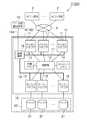
図1は、第1の実施の形態による記憶システム1の構成を示す。この記憶システム1は、複数のホスト計算機2がネットワーク3を介してストレージシステム4に接続されることにより構成されている。(1) First Embodiment (1-1) Configuration of Storage System According to First Embodiment FIG. 1 shows a configuration of a
上位装置としてのホスト計算機2は、CPU(Central Processing Unit)やメモリ等の情報処理資源を備えたコンピュータ装置であり、例えばパーソナルコンピュータや、ワークステーション、メインフレームコンピュータなどから構成される。ホスト計算機2は、キーボード、スイッチやポインティングデバイス、マイクロフォン等の情報入力装置(図示せず)と、モニタディスプレイやスピーカ等の情報出力装置(図示せず)とを備えている。 The
ネットワーク3は、例えばSAN(Storage Area Network)、LAN(Local Area Network)、インターネット、公衆回線又は専用回線などから構成される。このネットワーク3を介したホスト計算機2及びストレージシステム4間の通信は、例えばネットワーク3がSANである場合にはファイバーチャネルプロトコルに従って行われ、ネットワーク3がLANである場合にはTCP/IP(Transmission Control Protocol/Internet Protocol)プロトコルに従って行われる。 The
ストレージシステム4は、データの入出力を制御するコントロール部10と、データを記憶する複数のディスクデバイス21からなる記憶デバイス部20とを備えて構成されている。 The
コントロール部10は、複数のチャネルアダプタ11、接続部12、共有メモリ13、キャッシュメモリ14、複数のディスクアダプタ15及び管理端末16を備えて構成されている。 The
各チャネルアダプタ11は、それぞれマイクロプロセッサ、メモリ及び通信インタフェース等を備えたマイクロコンピュータシステムとして構成されており、それぞれネットワーク3や他のストレージシステム等に接続するためのポートを備える。チャネルアダプタ11は、ホスト計算機2からネットワーク3を介して送信される各種コマンドを解釈して対応する処理を実行する。各チャネルアダプタ11のポートには、それぞれを識別するためのネットワークアドレス(例えば、IPアドレスやWWN)が割り当てられており、これにより各チャネルアダプタ11がそれぞれ個別にNAS(Network Attached Storage)として振る舞うことができるようになされている。 Each
接続部12は、チャネルアダプタ11、共有メモリ13、キャッシュメモリ14及びディスクアダプタ15と接続されている。チャネルアダプタ11、共有メモリ13、キャッシュメモリ14及びディスクアダプタ15間でのデータやコマンドの授受は、この接続部12を介して行われる。接続部12は、例えば高速スイッチングによりデータ伝送を行う超高速クロスバススイッチなどのスイッチ又はバス等で構成されている。 The
共有メモリ13及びキャッシュメモリ14は、チャネルアダプタ11及びディスクアダプタ15により共有される記憶メモリである。共有メモリ13は、ストレージシステム4全体の構成に関する種々のシステム構成情報、各種プログラムや各種テーブルを記憶したり、書込み要求や読出し要求等のコマンドを記憶するために利用される。なお、本実施の形態において、共有メモリ13に記憶されている各種プログラムや各種テーブルについては、後述する。また、キャッシュメモリ14は、主に、ストレージシステム4に入出力する書込み対象や読出し対象のデータを一時的に記憶するために利用される。 The shared
各ディスクアダプタ15は、マイクロプロセッサやメモリ等を備えたマイクロコンピュータシステムとして構成され、記憶デバイス部20内のディスクデバイス21との通信時におけるプロトコル制御を行うインタフェースとして機能する。これらディスクアダプタ15は、例えばファイバーチャネルケーブルを介して記憶デバイス部20内の対応するディスクデバイス21と接続されており、ファイバーチャネルプロトコルに従ってこれらディスクデバイス21との間のデータの授受を行う。 Each
管理端末16は、ストレージシステム4全体の動作を制御する端末装置であり、例えばノート型のパーソナルコンピュータから構成される。管理端末16は、LAN17を介して各チャネルアダプタ11とそれぞれ接続され、LAN18を介して各ディスクアダプタ15とそれぞれ接続されている。オペレータは、管理端末16を用いてシステム構成情報を定義することができ、またこの定義したシステム構成情報を、チャネルアダプタ11又はディスクアダプタ15と接続部12とを経由して、共有メモリ13に格納することができる。 The
ユーザ用管理端末19は、ユーザからのストレージシステム4の状態や構成変更等を管理するコンピュータシステムである。ユーザ用管理端末19は、管理端末16と通信ネットワーク19Aを介して接続されており、管理端末16を介してストレージシステム4の
各制御状態を示す情報を取得し、また、管理端末16を介してストレージシステム4に各種の指示を与える。The
一方、記憶デバイス部20のディスクデバイス21としては、例えばSCSI(Small Computer System Interface)ディスク等の高価なディスク、又はSATA(Serial AT Attachment)ディスクや光ディスク等の安価なディスクが適用される。 On the other hand, as the
記憶デバイス部20の各ディスクデバイス21は、コントロール部10によりRAID方式で運用される。1又は複数のディスクデバイス21により提供される物理的な記憶領域上に、1又は複数の論理的なボリューム(以下、これを物理論理ボリュームと呼ぶ)が設定される。そしてデータは、この物理論理ボリューム内に所定大きさのブロック(以下、これを論理ブロックと呼ぶ)単位で記憶される。 Each
各論理ボリュームには、それぞれ固有の識別子(以下、これをLUN(Logical Unit Number)と呼ぶ)が付与される。本実施の形態の場合、データの入出力は、このLUNと、各論理ブロックにそれぞれ付与されるその論理ブロックに固有の番号(LBA:Logical Block Address)とを組み合わせたものをアドレスとして、当該アドレスを指定して行われる。 Each logical volume is given a unique identifier (hereinafter referred to as LUN (Logical Unit Number)). In the case of the present embodiment, data input / output is performed by using the combination of this LUN and a unique number (LBA: Logical Block Address) assigned to each logical block as an address. It is done by specifying.
(1−2)第1の実施の形態による記憶領域の割当て処理
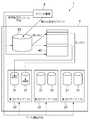
次に、本実施の形態における記憶システム1のストレージシステム4において、仮想論理ボリュームに記憶領域を割り当てる割当て処理について図2〜図12を参照して説明する。図2は、かかる割当て処理の内容を概略的に示した概念図である。(1-2) Storage Area Allocation Processing According to First Embodiment Next, allocation processing for allocating storage areas to virtual logical volumes in the
この場合、ストレージシステム4は、ホスト計算機2から送信されるデータを格納するための物理論理ボリューム31と、マッピングテーブル40を参照することにより、当該物理論理ボリューム31の記憶領域を動的に割り当て、ホスト計算機2に提供する仮想的な論理ボリュームである仮想論理ボリューム33とを有している。 In this case, the
そして、ストレージシステム4では、物理論理ボリューム31を保持するためのプール領域を複数作成し、プール領域32内の物理論理ボリューム31の記憶領域を仮想論理ボリューム33に割り当てる際の、当該記憶領域の割当てサイズを、プール領域32ごとに設定し、ホスト計算機2からデータが送信されたときに、仮想論理ボリューム対応づけられたプール領域32を固定的に選択して、当該プール領域32内の物理論理ボリューム31の記憶領域を仮想論理ボリューム33に割り当てることを特徴の1つにしている。なお、詳細な処理については、後述する。 In the
図3は、共有メモリ13に格納されている、本実施の形態による記憶領域の割当て処理にかかる各種プログラム及び各種テーブルを示している。この場合、共有メモリ13には、マッピングテーブル40、プール領域管理テーブル50、仮想論理ボリューム管理テーブル60、論理ボリューム構成テーブル70、空き記憶領域管理ビットマップ80、プール領域作成処理プログラム90、仮想論理ボリューム作成処理プログラム100及びコマンド処理プログラム110が格納されている。なお、プール領域作成処理プログラム90、仮想論理ボリューム作成処理プログラム100及びコマンド処理プログラム110については、後述する。 FIG. 3 shows various programs and various tables stored in the shared
図4は、マッピングテーブル40の構成を示している。マッピングテーブル40は、仮想論理ボリューム33ごとに管理され、当該仮想論理ボリューム33と物理論理ボリューム31との対応を保持するテーブルであり、仮想論理ボリュームアドレス管理欄41と、物理論理ボリューム識別番号管理欄42と、物理論理ボリュームアドレス管理欄43とにより構成されている。 FIG. 4 shows the configuration of the mapping table 40. The mapping table 40 is a table that is managed for each virtual
仮想論理ボリュームアドレス管理欄41は、例えば、仮想論理ボリューム33のLBA等でなる、仮想論理ボリューム33のアドレスを管理する。物理論理ボリューム識別番号管理欄42は、当該仮想論理ボリューム33のアドレスに対応づけられた、例えば、物理論理ボリューム31のLUN等でなる、物理論理ボリューム31の識別番号を管理する。物理論理ボリューム割当てアドレス管理欄43は、当該仮想論理ボリューム33のアドレスに対応づけられた、例えば、物理論理ボリューム31のLBA等でなる、物理論理ボリューム31のアドレスを管理する。 The virtual logical volume
この場合、例えば、仮想論理ボリュームアドレス「0」は、物理論理ボリューム識別番号「0x0001」の物理論理ボリューム31の物理論理ボリューム割当てアドレス「0」と対応づけられていることとなる。 In this case, for example, the virtual logical volume address “0” is associated with the physical logical volume assignment address “0” of the physical
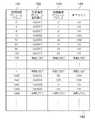
図5は、プール領域管理テーブル50の構成を示している。プール領域管理テーブル50は、プール領域32と物理論理ボリューム31との対応を保持するテーブルであり、プール領域識別番号管理欄51と、物理論理ボリューム識別番号管理欄52と、エミュレーションタイプ管理欄53と、物理論理ボリュームサイズ管理欄54と、割当てサイズ管理欄55と、空き数管理欄56とにより構成されている。 FIG. 5 shows the configuration of the pool area management table 50. The pool area management table 50 is a table that holds the correspondence between the
プール領域識別番号管理欄51は、プール領域32の識別番号を管理する。物理論理ボリューム識別番号管理欄52は、プール領域32に保持されている物理論理ボリューム31の識別番号を管理する。 The pool area identification
エミュレーションタイプ管理欄53は、物理論理ボリューム31に格納されるデータが送信されたホスト計算機2のエミュレーションのタイプを管理する。なお、エミュレーションとは、あるハードウェア向けに開発されたソフトウェアを、設計の異なる他のハードウェア上で実行させることであり、例えば、「OPEN−V」がエミュレーションタイプ管理欄53に格納されている場合には、ストレージシステム4において「OPEN−V」のソフトウェアを実行して、「OPEN−V」のホスト計算機2のデータを格納することを示している。またなお、例えば、「OPEN−V」又は「OPEN−3」は、いわゆるWindows(登録商標)等のオープン系のコンピュータシステムであり、「3390−3」は、いわゆるメインフレーム系のコンピュータシステムである。 The emulation
物理論理ボリュームサイズ管理欄54は、物理論理ボリューム31のボリュームサイズを管理する。割当てサイズ管理欄55は、プール領域32内の物理論理ボリューム31の記憶領域を仮想論理ボリューム33に割り当てる際の、当該記憶領域の割当てサイズを管理する。空き記憶領域数管理欄56は、物理論理ボリューム31のボリュームサイズを記憶領域の割当てサイズにより除算することにより算出した、物理論理ボリューム31の記憶領域の数のうち、データが格納されていない空き記憶領域の数を管理する。 The physical logical volume
なお、プール領域32は、物理論理ボリューム31に格納されるデータを送信するホスト計算機2のエミュレーションのスロットタイプが同一であり、かつ割当てサイズが同一である場合には、図2に示すように、同一のプール領域32に複数の物理論理ボリューム31を保持することができる。 In the
この場合、例えば、プール領域識別番号「0」のプール領域32は、エミュレーションタイプ「OPEN−V」、物理論理ボリュームサイズ「300G(GB)」、空き数「307200」である物理論理ボリューム識別番号「0x0001」の物理論理ボリューム31と、エミュレーションタイプ「OPEN−V」、物理論理ボリュームサイズ「200G」、空き数「204800」である物理論理ボリューム識別番号「0x0002」の物理論理ボリューム31が保持されていることとなり、割当てサイズ「1M(MB)」に設定されている。 In this case, for example, the
図6は、仮想論理ボリューム管理テーブル60の構成を示している。仮想論理ボリューム管理テーブル60は、仮想論理ボリューム33とプール領域32との対応を保持するテーブルであり、仮想論理ボリューム識別番号管理欄61と、プール領域識別番号管理欄62とにより構成されている。 FIG. 6 shows the configuration of the virtual logical volume management table 60. The virtual logical volume management table 60 is a table that holds the correspondence between the virtual
仮想論理ボリューム識別番号管理欄61は、例えば、仮想論理ボリューム33のLUN等でなる、仮想論理ボリューム33の識別番号を管理する。プール領域識別番号管理欄62は、仮想論理ボリューム33の識別番号に、ユーザ等により選択されることにより割り当てられた、プール領域32の識別番号を管理する。 The virtual logical volume identification
この場合、例えば、仮想論理ボリューム識別番号「0x0100」の仮想論理ボリューム33は、プール領域「0」のプール領域32が割り当てられていることとなる。 In this case, for example, the
図7は、論理ボリューム構成テーブル70の構成を示している。論理ボリューム構成テーブル70は、物理論理ボリューム31及び仮想論理ボリューム33の構成並びにホスト計算機2との対応を保持するテーブルであり、論理ボリューム識別番号管理欄71と、エミュレーションタイプ管理欄72と、論理ボリュームサイズ管理欄73と、接続ポート識別番号管理欄74とにより構成されている。 FIG. 7 shows the configuration of the logical volume configuration table 70. The logical volume configuration table 70 is a table that holds the configuration of the physical
論理ボリューム識別番号管理欄71は、例えば、物理論理ボリューム31又は仮想論理ボリューム33のLUN等でなる、物理論理ボリューム31又は仮想論理ボリューム33の識別番号を管理する。エミュレーションタイプ管理欄72は、物理論理ボリューム31又は仮想論理ボリューム33に格納されるデータが送信されたホスト計算機2のエミュレーションのタイプを管理する。論理ボリュームサイズ管理欄54は、物理論理ボリューム31又は仮想論理ボリューム33のボリュームサイズを管理する。接続ポート識別番号管理欄74は、ホスト計算機2と接続するための接続ポートを管理する。 The logical volume identification
この場合、例えば、論理ボリューム識別番号「0x0100」の仮想論理ボリューム33は、エミュレーションタイプ「OPEN−V」、論理ボリュームサイズ「500G」、接続ポート「1A」であることとなる。 In this case, for example, the virtual
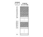
図8は、空き記憶領域管理ビットマップ80を概略的に示した概念図を示している。空き記憶領域管理ビットマップ80は、物理論理ボリューム31ごとに管理されており、物理論理ボリュームアドレスごとに仮想論理ボリューム33に割り当てられているか否かを管理する。この場合、空き記憶領域管理ビットマップ80は、網掛け部分となっている物理論理ボリュームアドレスの記憶領域については、仮想論理ボリューム33に割り当てられており、網掛け部分となっていない物理論理ボリュームアドレスの記憶領域については、仮想論理ボリューム33に割り当てられていないことを示している。 FIG. 8 is a conceptual diagram schematically showing the free storage
図9は、空き記憶領域管理ビットマップ80の実際上の管理図を示している。実際上、空き記憶領域管理ビットマップ80は、図8における仮想論理ボリューム33に割り当てられている、網掛け部分となっている物理論理ボリュームアドレスの記憶領域については、「使用中」を示す「BitON(1)」で管理し、仮想論理ボリューム33に割り当てられていない、網掛け部分となっていない物理論理ボリュームアドレスの記憶領域については、「未使用」を示す「BitOFF(0)」で管理する。 FIG. 9 shows an actual management chart of the free storage
ここで、第1の実施の形態における記憶システム1のプール領域作成処理について説明する。図10は、この記憶システム1におけるプール領域作成処理に関するストレージシステム4の具体的な処理手順を示したフローチャートである。 Here, the pool area creation processing of the
ストレージシステム4のチャネルアダプタ11は、初期時、物理論理ボリューム31を保持するプール領域32を作成するプログラムであるプール領域作成処理プログラム90を実行することにより、図10に示すプール領域作成処理手順RT1に従って、ユーザ等の操作によりユーザ用管理端末19から管理端末16を介してプール領域作成コマンドを受信するのを待機モードで待ち受ける(S1)。 The
なお、プール領域作成コマンドには、例えば、ユーザ等により指定された作成するプール領域32のプール領域識別番号、プール領域32に保持した物理論理ボリューム31の記憶領域を仮想論理ボリューム33に割り当てる際の割当てサイズや、予め図7に示されている論理ボリューム構成テーブル70の物理論理ボリューム31を参照することにより指定された、プール領域32が保持する物理論理ボリューム31の構成情報(物理論理ボリューム識別番号、エミュレーションタイプ、物理論理ボリュームサイズ)等の情報が含まれている。 In the pool area creation command, for example, the pool area identification number of the
やがて、チャネルアダプタ11は、ユーザ用管理端末19から管理端末16を介してプール領域作成コマンドを受信する(S1:YES)と、空き記憶領域管理ビットマップ80を作成し、当該空き記憶領域管理ビットマップ80を初期化する(S2)。 Eventually, when the
具体的に、チャネルアダプタ11は、プール領域作成コマンドに従って、ユーザ等により指定された物理論理ボリューム31ごとに空き記憶領域管理ビットマップ80を作成し、空き記憶領域管理ビットマップ80の物理論理ボリュームアドレスの記憶領域にデータが格納されている場合には、当該物理論理ボリュームアドレスの管理状態を「1」に設定し、空き記憶領域管理ビットマップ80の物理論理ボリュームアドレスの記憶領域にデータが格納されていない場合には、当該物理論理ボリュームアドレスの管理状態を「0」に設定して、空き記憶領域管理ビットマップ80を更新する。 Specifically, the
続いて、チャネルアダプタ11は、ユーザ用管理端末19から管理端末16を介して受信したプール領域作成コマンドに基づいて、プール領域管理テーブル50を作成し、又は更新する(S3)。 Subsequently, the
具体的に、チャネルアダプタ11は、プール領域管理テーブル50が作成されていない場合には、プール領域管理テーブル50を作成して、プール領域作成コマンドに従って、ユーザ等により指定された物理論理ボリューム31の構成情報、プール領域識別番号及び割当てサイズをプール領域管理テーブル50の対応位置に格納し、物理論理ボリュームサイズ及び割当てサイズ並びに空き記憶領域管理ビットマップ80に基づいて、当該物理論理ボリュームごとに空き記憶領域の数を算出して、当該空き記憶領域の数をプール領域管理テーブル50の対応位置に格納する。 Specifically, if the pool area management table 50 has not been created, the
また、チャネルアダプタ11は、プール領域管理テーブル50が作成されている場合には、プール領域作成コマンドに従って、ユーザ等により指定された物理論理ボリューム31の構成情報、プール領域識別番号及び割当てサイズをプール領域管理テーブル50の対応位置に格納し、物理論理ボリュームサイズ及び割当てサイズ並びに空き記憶領域管理ビットマップ80に基づいて、当該物理論理ボリュームごとに空き記憶領域の数を算出して、当該空き記憶領域数をプール領域管理テーブル50の対応位置に格納し、プール領域管理テーブル50を更新する。 Further, when the pool area management table 50 is created, the
やがて、チャネルアダプタ11は、この後、図10に示すプール領域作成処理手順RT1を終了する(S4)。 Eventually, the
次に、第1の実施の形態における記憶システム1の仮想論理ボリューム作成処理について説明する。図11は、この記憶システム1における仮想論理ボリューム作成処理に関するストレージシステム4の具体的な処理手順を示したフローチャートである。 Next, the virtual logical volume creation processing of the
チャネルアダプタ11は、初期時、仮想論理ボリューム33を作成するプログラムである仮想論理ボリューム作成処理プログラム100を実行することにより、図11に示す仮想論理ボリューム作成処理手順RT2に従って、ユーザ等の操作によりユーザ用管理端末19から管理端末16を介して仮想論理ボリューム作成コマンドを受信するのを待機モードで待ち受ける(S11)。 The
なお、仮想論理ボリューム作成コマンドには、例えば、ユーザ等により指定された、作成する仮想論理ボリューム33の仮想論理ボリューム識別番号、作成する仮想論理ボリューム33の仮想論理ボリュームサイズ、作成する仮想論理ボリューム33をホスト計算機2に接続するための接続ポートや、作成する仮想論理ボリューム33を割り当てるプール領域32のプール領域識別番号又は作成する仮想論理ボリューム33に割り当てる記憶領域の割当てサイズ等の情報が含まれている。 In the virtual logical volume creation command, for example, the virtual logical volume identification number of the virtual
やがて、チャネルアダプタ11は、ユーザ等の操作によりユーザ用管理端末19から管理端末16を介して仮想論理ボリューム作成コマンドを受信する(S11:YES)と、仮想論理ボリューム作成コマンドによりプール領域識別番号が指定されたか否かをチェックする(S12)。 Eventually, when the
そして、チャネルアダプタ11は、仮想論理ボリューム作成コマンドによりプール領域識別番号が指定されていない場合(S12:NO)には、指定された割当てサイズのプール領域識別番号を取得する(S13)。 If the pool area identification number is not designated by the virtual logical volume creation command (S12: NO), the
具体的に、チャネルアダプタ11は、例えば、仮想論理ボリューム作成コマンドにより割当てサイズ「1M」が指定された場合には、プール領域管理テーブル50を参照して、割当てサイズ管理欄55の割当てサイズ「1M」であるプール領域識別番号「0」を取得する。 Specifically, for example, when the allocation size “1M” is designated by the virtual logical volume creation command, the
なお、チャネルアダプタ11は、仮想論理ボリューム作成コマンドにより指定された割当てサイズがプール領域管理テーブル50により管理されていない場合には、当該指定された割当てサイズに最も近い割当てサイズのプール領域識別番号を取得するようになされている。 When the allocation size specified by the virtual logical volume creation command is not managed by the pool area management table 50, the
これに対して、チャネルアダプタ11は、仮想論理ボリューム作成コマンドによりプール領域識別番号が指定されている場合(S12:YES)、又は指定された割当てサイズのプール領域識別番号を取得した場合(S13)には、ホスト計算機2から受信した仮想論理ボリューム作成コマンドに基づいて、仮想論理ボリューム管理テーブル60を作成し、又は更新する(S14)。 On the other hand, when the pool area identification number is designated by the virtual logical volume creation command (S12: YES), or the
具体的に、チャネルアダプタ11は、仮想論理ボリューム管理テーブル60が作成されていない場合には、仮想論理ボリューム管理テーブル60を作成して、仮想論理ボリューム作成コマンドに従って、ユーザ等により指定された仮想論理ボリューム識別番号、及びユーザ等により指定された、又は取得したプール領域識別番号を仮想論理ボリューム管理テーブル60の対応位置に格納する。 Specifically, if the virtual logical volume management table 60 has not been created, the
また、チャネルアダプタ11は、仮想論理ボリューム管理テーブル60が作成されている場合には、仮想論理ボリューム作成コマンドに従って、ユーザ等により指定された仮想論理ボリューム識別番号、及びユーザ等により指定された、又は取得したプール領域識別番号を仮想論理ボリューム管理テーブル60の対応位置に格納し、仮想論理ボリューム管理テーブル60を更新する。 In addition, when the virtual logical volume management table 60 has been created, the
このようにして、チャネルアダプタ11は、仮想論理ボリューム管理テーブル60により、仮想論理ボリューム33に割り当てる記憶領域の物理論理ボリューム31が保持されているプール領域32を固定的に選択することができるようになされている。 In this way, the
続いて、チャネルアダプタ11は、ユーザ用管理端末19から管理端末16を介して受信したプール領域作成コマンドに基づいてマッピングテーブル40を作成する(S15)。具体的に、チャネルアダプタ11は、作成した仮想論理ボリューム33ごとにマッピングテーブル40を作成し、仮想論理ボリューム作成コマンドに従って、ユーザ等により指定された仮想論理ボリュームサイズ分の仮想論理ボリュームアドレスをマッピングテーブル40の対応位置に格納する。 Subsequently, the
続いて、チャネルアダプタ11は、ユーザ用管理端末19から管理端末16を介して受信したプール領域作成コマンドに基づいて論理ボリューム構成テーブル70を更新する(S16)。具体的に、チャネルアダプタ11は、仮想論理ボリューム作成コマンドに従って、ユーザ等により指定された仮想論理ボリューム識別番号(論理ボリューム識別番号)、仮想論理ボリュームサイズ(論理ボリュームサイズ)及び接続ポートを論理ボリューム構成テーブル70の対応位置に格納し、仮想論理ボリューム管理テーブル60を参照することにより、当該仮想論理ボリューム識別番号に対応づけられたプール領域識別番号のエミュレーションタイプを論理ボリューム構成テーブル70の対応位置に格納する。 Subsequently, the
やがて、チャネルアダプタ11は、この後、図11に示す仮想論理ボリューム作成処理手順RT2を終了する(S17)。 Eventually, the
次に、第1の実施の形態における記憶システム1のデータ書込み要求時のコマンド処理について説明する。図12は、この記憶システム1におけるデータ書込み要求時のコマンド処理に関するストレージシステム4の具体的な処理手順を示したフローチャートである。 Next, command processing at the time of data write request of the
チャネルアダプタ11は、初期時、ホスト計算機2から受信したデータ書込み要求のコマンドにより記憶領域にデータを書き込むプログラムであるコマンド処理プログラム110を実行することにより、図12に示すデータ書込み要求時のコマンド処理手順RT3に従って、ユーザ等の操作によりホスト計算機2からデータ書込み要求のコマンドを受信するのを待機モードで待ち受ける(S21)。 The
やがて、チャネルアダプタ11は、ホスト計算機2からデータ書込み要求のコマンドを受信する(S21:YES)と、仮想論理ボリューム33の仮想論理ボリュームアドレスに物理論理ボリューム31の記憶領域が割り当てられているか否かをチェックする(S22)。 Eventually, when the
具体的に、チャネルアダプタ11は、マッピングテーブル40を参照することにより、データ書込み要求のコマンドに含まれる書込み対象のデータを書き込むべき仮想論理ボリュームアドレスに、物理論理ボリューム識別番号及び物理論理ボリュームアドレスが対応付けられているか否かをチェックする。 Specifically, the
そして、チャネルアダプタ11は、仮想論理ボリューム33の仮想論理ボリュームアドレスに物理論理ボリューム31の記憶領域が割り当てられていない場合(S22:NO)には、仮想論理ボリューム33に対応づけられているプール領域32の物理論理ボリューム31に空き記憶領域があるか否かをチェックする(S23)。 If the storage area of the physical
具体的に、チャネルアダプタ11は、仮想論理ボリューム管理テーブル60を参照することにより、仮想論理ボリューム識別番号に対応づけられているプール領域識別番号を取得し、その後、プール領域管理テーブル50を参照することにより、当該プール領域識別番号に対応づけられている空き記憶領域数があるか否かをチェックする。 Specifically, the
そして、チャネルアダプタ11は、仮想論理ボリューム33に対応づけられているプール領域32の物理論理ボリューム31に空き記憶領域がない場合(S23:NO)には、プール領域32の物理論理ボリューム31を閉塞させて、その後、図12に示すデータ書込み要求時のコマンド処理手順RT3を終了する(S27)。 Then, when there is no free storage area in the physical
これに対して、チャネルアダプタ11は、仮想論理ボリューム33に対応づけられているプール領域32の物理論理ボリューム31に空き記憶領域がある場合(S23:YES)には、マッピングテーブル40を更新し、仮想論理ボリューム33に対応するプール領域32に保持された物理論理ボリューム31の記憶領域を割り当てる(S24)。 On the other hand, the
具体的に、チャネルアダプタ11は、ビットマップ管理テーブル80を参照することにより、割り当てる記憶領域の物理論理ボリュームアドレスの開始アドレスを確定し、その後、マッピングテーブル40を参照することにより、マッピングテーブル40の当該仮想論理ボリュームアドレスの対応位置に物理論理ボリューム31の物理論理ボリューム識別番号及び割り当てるべき物理論理ボリューム31の記憶領域の物理論理ボリュームアドレスをマッピングテーブル40の当該仮想論理ボリュームアドレスの対応位置に格納し、マッピングテーブル40を更新する。 Specifically, the
この場合、チャネルアダプタ11は、空き記憶領域数がある物理論理ボリュームが複数ある場合には、空き記憶領域が最も多い物理論理ボリューム31の記憶領域を割り当てるようになされている。 In this case, when there are a plurality of physical logical volumes having the number of free storage areas, the
続いて、チャネルアダプタ11は、マッピングテーブル40の更新に伴って、空き記憶領域管理ビットマップ80を変更する(S25)。具体的に、チャネルアダプタ11は、マッピングテーブル40を参照することにより、空き記憶領域管理ビットマップ80における、割り当てた物理論理ボリューム31の記憶領域の物理論理ボリュームアドレスの管理状態を「1」にすることにより、空き記憶領域管理ビットマップ80を変更する。 Subsequently, the
これに対して、チャネルアダプタ11は、仮想論理ボリューム33の仮想論理ボリュームアドレスに物理論理ボリューム31の記憶領域が割り当てられている場合(S22:YES)、又は仮想論理ボリューム33に記憶領域を割り当て、マッピングテーブル40を更新し、空き記憶領域管理ビットマップ80を変更した場合(S24、S25)には、書き込むべき仮想論理ボリュームアドレスに対応する物理論理ボリューム31の記憶領域に書込み対象のデータを書き込む(S26)。 In contrast, the
やがて、チャネルアダプタ11は、この後、図12に示すデータ書込み要求時のコマンド処理手順RT3を終了する(S27)。 Eventually, the
このようにして、記憶システム1では、物理論理ボリューム31を保持するためのプール領域を複数作成し、プール領域32内の物理論理ボリューム31の記憶領域を仮想論理ボリューム33に割り当てる際の、当該記憶領域の割当てサイズを、プール領域32ごとに設定し、ホスト計算機2からデータが送信されたときに、仮想論理ボリューム対応づけられたプール領域32を固定的に選択して、当該プール領域32内の物理論理ボリューム31の記憶領域を仮想論理ボリューム33に割り当てる。 In this way, the
従って、記憶システム1では、ホスト計算機2から送信されるデータに対して、大きすぎる割当てサイズの記憶領域や、小さすぎる割当てサイズの記憶領域を複数割り当てることを有効に防止し、当該データに対して、適切な割当てサイズの記憶領域を割り当てることができ、物理論理ボリュームの記憶領域を効率的に運用することができる。 Accordingly, the
(2)第2の実施の形態
第2の実施の形態による記憶システム120は、マッピングテーブル40の構成が異なること、仮想論理ボリューム作成処理プログラム100及びコマンド処理プログラム110の処理内容が異なること、仮想論理ボリューム管理テーブル60を有していないことを除いて、第1の実施の形態による記憶システム1と同様に構成されている。(2) Second Embodiment The
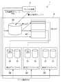
本実施の形態における記憶システム120のストレージシステム130において、仮想論理ボリュームに記憶領域を割り当てる割当て処理について図13〜図17を参照して説明する。図13は、かかる割当て処理の内容を概略的に示した概念図である。 An allocation process for allocating a storage area to a virtual logical volume in the
この場合、ストレージシステム130では、物理論理ボリューム31を保持するためのプール領域を複数作成し、プール領域32内の物理論理ボリューム31の記憶領域を仮想論理ボリューム33に割り当てる際の、当該記憶領域の割当てサイズを、プール領域32ごとに設定し、ホスト計算機2からデータが送信されたときの、当該データのデータサイズに応じて、プール領域32を、複数のプール領域32から可変的に選択して、当該プール領域32内の物理論理ボリューム31の記憶領域を仮想論理ボリューム33に割り当てることを特徴の1つにしている。なお、詳細な処理については、後述する。 In this case, the
図14は、共有メモリ13に格納されている、本実施の形態による記憶領域の割当て処理にかかる各種プログラム及び各種テーブルを示している。この場合、共有メモリ13には、マッピングテーブル140、プール領域管理テーブル50、論理ボリューム構成テーブル70、空き記憶領域管理ビットマップ80、プール領域作成処理プログラム90、仮想論理ボリューム作成処理プログラム150及びコマンド処理プログラム160が格納されている。なお、仮想論理ボリューム作成処理プログラム150及びコマンド処理プログラム160については、後述する。 FIG. 14 shows various programs and various tables stored in the shared
図15は、マッピングテーブル140の構成を示している。マッピングテーブル140は、仮想論理ボリューム33ごとに管理され、当該仮想論理ボリューム33と物理論理ボリューム31との対応を保持するテーブルであり、仮想論理ボリュームアドレス管理欄141と、物理論理ボリューム識別番号管理欄142と、物理論理ボリューム開始アドレス管理欄143と、割当てサイズ管理欄144とにより構成されている。 FIG. 15 shows the configuration of the mapping table 140. The mapping table 140 is a table that is managed for each virtual
仮想論理ボリュームアドレス管理欄41は、例えば、仮想論理ボリューム33のLBA等でなる、仮想論理ボリューム33のアドレスを管理する。物理論理ボリューム識別番号管理欄142は、当該仮想論理ボリューム33のアドレスに対応づけられた、例えば、物理論理ボリューム31のLUN等でなる、物理論理ボリューム31の識別番号を管理する。物理論理ボリューム割当てアドレス管理欄43は、当該仮想論理ボリューム33のアドレスに対応づけられた、例えば、物理論理ボリューム31のLBA等でなる、物理論理ボリューム31の開始アドレスを管理する。割当てサイズ管理欄144は、プール領域32内の物理論理ボリューム31の記憶領域を仮想論理ボリューム33に割り当てる際の、当該記憶領域の割当てサイズを管理する。 The virtual logical volume
この場合、例えば、仮想論理ボリュームアドレス「0」は、物理論理ボリューム識別番号「0x0007」の物理論理ボリューム31の物理論理ボリューム開始アドレス「0」から割当てサイズ「1M」分の記憶領域が対応づけられていることとなる。 In this case, for example, the virtual logical volume address “0” is associated with the storage area of the allocated size “1M” from the physical logical volume start address “0” of the physical
記憶システム120では、例えば、1つの仮想論理ボリュームアドレスの領域あたり256(KB)のデータサイズであったときに、ホスト計算機2から1(MB)の書込み要求のコマンドを受信した場合には、割り当てた物理論理ボリューム識別番号及び物理論理ボリューム開始アドレスから1(MB)の書き込みを行い、マッピングテーブル140に管理するものである。 In the
また、記憶システム120では、例えば、空き記憶領域を検索する際に、オープン系のコンピュータシステムの場合には、例えば、「n」番の論理ブロックから「m」個の論理ブロック分の書込み又は読出しが実施される(1論理ブロックは512(KB)である)ため、物理論理ボリューム開始アドレスを「512×n」とし、「512×m」分の記憶領域と、割当てサイズとが同じものを検索し、当該物理論理ボリュームアドレスがすべて「未使用」であるか否かをチェックする。 In the
また、記憶システム120では、例えば、空き記憶領域を検索する際に、メインフレーム系のコンピュータシステムの場合には、例えば、「n」番のシリンダの「m」番のディスクデバイス21に対しての書込み又は読出しが実施されるため、すべてのディスクデバイス21を換算して、物理論理ボリューム開始アドレスを確定する。この場合、記憶システム120では、「(n×15+m)×エミュレーションタイプにおけるサイズ(3380系は48(KB)、3390系は57(KB)である)」からのアドレスが「未使用」であるか否かをチェックする。 In the
ここで、第2の実施の形態における記憶システム120の仮想論理ボリューム作成処理について説明する。図16は、この記憶システム120における仮想論理ボリューム作成処理に関するストレージシステム130の具体的な処理手順を示したフローチャートである。 Here, the virtual logical volume creation processing of the
チャネルアダプタ11は、初期時、仮想論理ボリューム33を作成するプログラムである仮想論理ボリューム作成処理プログラム150を実行することにより、図16に示す仮想論理ボリューム作成処理手順RT4に従って、ユーザ等の操作によりホスト計算機2から仮想論理ボリューム作成コマンドを受信するのを待機モードで待ち受ける(S31)。 The
なお、仮想論理ボリューム作成コマンドには、例えば、ユーザ等により指定された、作成する仮想論理ボリューム33の仮想論理ボリューム識別番号、作成する仮想論理ボリューム33の仮想論理ボリュームサイズ、作成する仮想論理ボリューム33をホスト計算機2に接続するための接続ポート、作成する仮想論理ボリューム33に格納されるデータを送信するホスト計算機2のエミュレーションタイプ等の情報が含まれている。 In the virtual logical volume creation command, for example, the virtual logical volume identification number of the virtual
やがて、チャネルアダプタ11は、ユーザ等の操作によりユーザ用管理端末19から管理端末16を介して仮想論理ボリューム作成コマンドを受信する(S31:YES)と、ユーザ用管理端末19から管理端末16を介して受信したプール領域作成コマンドに基づいてマッピングテーブル40を作成する(S32)。具体的に、チャネルアダプタ11は、作成した仮想論理ボリューム33ごとにマッピングテーブル140を作成し、仮想論理ボリューム作成コマンドに従って、ユーザ等により指定された仮想論理ボリュームサイズ分の仮想論理ボリュームアドレスをマッピングテーブル140の対応位置に格納する。 Eventually, when the
続いて、チャネルアダプタ11は、ユーザ用管理端末19から管理端末16を介して受信したプール領域作成コマンドに基づいて論理ボリューム構成テーブル70を更新する(S33)。具体的に、チャネルアダプタ11は、仮想論理ボリューム作成コマンドに従って、ユーザ等により指定された仮想論理ボリューム識別番号(論理ボリューム識別番号)、仮想論理ボリュームサイズ(論理ボリュームサイズ)、接続ポート及びエミュレーションタイプを論理ボリューム構成テーブル70の対応位置に格納する。 Subsequently, the
やがて、チャネルアダプタ11は、この後、図16に示す仮想論理ボリューム作成処理手順RT4を終了する(S34)。 Eventually, the
次に、第2の実施の形態における記憶システム120のデータ書込み要求時のコマンド処理について説明する。図17は、この記憶システム120におけるデータ書込み要求時のコマンド処理に関するストレージシステム130の具体的な処理手順を示したフローチャートである。 Next, command processing at the time of a data write request of the
チャネルアダプタ11は、初期時、ホスト計算機2から受信したデータ書込み要求のコマンドにより記憶領域にデータを書き込むプログラムであるコマンド処理プログラム160を実行することにより、図17に示すデータ書込み要求時のコマンド処理手順RT5に従って、ユーザ等の操作によりホスト計算機2からデータ書込み要求のコマンドを受信するのを待機モードで待ち受ける(S41)。 The
やがて、チャネルアダプタ11は、ホスト計算機2からデータ書込み要求のコマンドを受信する(S41:YES)と、仮想論理ボリューム33の仮想論理ボリュームアドレスに物理論理ボリューム31の記憶領域が割り当てられているか否かをチェックする(S42)。 Eventually, when the
そして、チャネルアダプタ11は、仮想論理ボリューム33の仮想論理ボリュームアドレスに物理論理ボリューム31の記憶領域が割り当てられていない場合(S22:NO)には、プール領域管理テーブル50を参照することにより、仮想論理ボリューム33と同一のエミュレーションタイプであり、かつデータ書込み要求のコマンドに含まれる書込み対象のデータのデータサイズに最も近い割当てサイズであるプール領域識別番号を取得する(S43)。 Then, when the storage area of the physical
このようにして、チャネルアダプタ11は、プール領域管理テーブル50により、仮想論理ボリューム33に割り当てる記憶領域の物理論理ボリューム31が保持されているプール領域32を可変的に選択することができるようになされている。 In this way, the
続いて、チャネルアダプタ11は、仮想論理ボリューム33に対応づけられているプール領域32の物理論理ボリューム31に空き記憶領域があるか否かをチェックする(S44)。 Subsequently, the
具体的に、チャネルアダプタ11は、プール領域管理テーブル50を参照することにより、当該プール領域識別番号に対応づけられている空き記憶領域数があるか否かをチェックする。 Specifically, the
そして、チャネルアダプタ11は、仮想論理ボリューム33に対応づけられているプール領域32の物理論理ボリューム31に空き記憶領域がない場合(S44:NO)には、プール領域32の物理論理ボリューム31を閉塞させて、その後、図17に示すデータ書込み要求時のコマンド処理手順RT5を終了する(S48)。 Then, when there is no free storage area in the physical
これに対して、チャネルアダプタ11は、仮想論理ボリューム33に対応づけられているプール領域32の物理論理ボリューム31に空き記憶領域がある場合(S44:YES)には、マッピングテーブル140を更新し、仮想論理ボリューム33に対応するプール領域32に保持された物理論理ボリューム31の記憶領域を割り当てる(S45)。 On the other hand, when there is a free storage area in the physical
具体的に、チャネルアダプタ11は、ビットマップ管理テーブル80を参照することにより、割り当てる記憶領域の物理論理ボリュームアドレスの開始アドレスを確定し、その後、マッピングテーブル140を参照することにより、マッピングテーブル140の当該仮想論理ボリュームアドレスの対応位置に物理論理ボリューム31の物理論理ボリューム識別番号、割り当てるべき物理論理ボリューム31の記憶領域の物理論理ボリューム開始アドレス及び割り当てるべき記憶領域の割当てサイズをマッピングテーブル140の当該仮想論理ボリュームアドレスの対応位置に格納し、マッピングテーブル140を更新する。 Specifically, the
この場合、チャネルアダプタ11は、空き記憶領域数がある物理論理ボリュームが複数ある場合には、空き記憶領域が最も多い物理論理ボリューム31の記憶領域を割り当てるようになされている。 In this case, when there are a plurality of physical logical volumes having the number of free storage areas, the
続いて、チャネルアダプタ11は、マッピングテーブル140の更新に伴って、空き記憶領域管理ビットマップ80を変更する(S46)。具体的に、チャネルアダプタ11は、マッピングテーブル140を参照することにより、空き記憶領域管理ビットマップ80における、割り当てた物理論理ボリューム31の記憶領域の物理論理ボリュームアドレスの管理状態を「1」にすることにより、空き記憶領域管理ビットマップ80を変更する。 Subsequently, the
これに対して、チャネルアダプタ11は、仮想論理ボリューム33の仮想論理ボリュームアドレスに物理論理ボリューム31の記憶領域が割り当てられている場合(S42:YES)、又は仮想論理ボリューム33に記憶領域を割り当て、マッピングテーブル40を更新し、空き記憶領域管理ビットマップ80を変更した場合(S43〜S46)には、書き込むべき仮想論理ボリュームアドレスに対応する物理論理ボリューム31の記憶領域に書込み対象のデータを書き込む(S47)。 In contrast, the
やがて、チャネルアダプタ11は、この後、図17に示すデータ書込み要求時のコマンド処理手順RT5を終了する(S48)。 Eventually, the
このようにして、記憶システム120では、物理論理ボリューム31を保持するためのプール領域を複数作成し、プール領域32内の物理論理ボリューム31の記憶領域を仮想論理ボリューム33に割り当てる際の、当該記憶領域の割当てサイズを、プール領域32ごとに設定し、ホスト計算機2からデータが送信されたときの、当該データのデータサイズに応じて、プール領域32を、複数のプール領域32から可変的に選択して、当該プール領域32内の物理論理ボリューム31の記憶領域を仮想論理ボリューム33に割り当てる。 In this way, the
従って、記憶システム1では、ホスト計算機2から送信されるデータに対して、当該データのデータサイズに応じて、プール領域32を、複数のプール領域32から可変的に選択するため、当該データごとに適切な割当てサイズの記憶領域を割り当てることができ、物理論理ボリュームの記憶領域を一段と効率的に運用することができる。 Therefore, in the
なお、本実施の形態では、図18に示すように、メインフレーム系のコンピュータシステムの環境においては、論理ボリュームを先頭から末尾の論理ボリュームアドレスに向かって順に使用する(論理ボリュームをシーケンシャルに使用する((1)→(3)))ようになされているため、例えば、1(GB)程度のように、割当てサイズを大きめに設定することにより、物理論理ボリュームの記憶領域を一段と効率的に運用することができる。 In this embodiment, as shown in FIG. 18, in the environment of a mainframe computer system, logical volumes are used in order from the beginning to the end logical volume address (logical volumes are used sequentially). ((1) → (3))), for example, the storage size of the physical logical volume is more efficiently operated by setting a larger allocation size, for example, about 1 (GB). can do.
また、本実施の形態では、図19に示すように、オープン系のコンピュータシステムの環境においては、論理ボリュームを故意に空き記憶領域作成して使用する(論理ボリュームをランダムに使用する((1)→(3)))ようになされているため、例えば、1〜10(MB)程度のように、割当てサイズを小さめに設定することにより、物理論理ボリュームの記憶領域を一段と効率的に運用することができる。 In the present embodiment, as shown in FIG. 19, in the environment of an open computer system, a logical volume is intentionally created and used (a logical volume is randomly used ((1)). → (3))), the storage area of the physical logical volume can be operated more efficiently by setting a smaller allocation size, for example, about 1 to 10 (MB). Can do.
さらに、本実施の形態では、ユーザ等により指定されなくても(割当てサイズが指定されていなくとも)、ホスト計算機2からのコマンドに基づいて、ホスト計算機2がメインフレーム系のコンピュータシステムであるか、又はオープン系のコンピュータシステムであるかを判定し、メインフレーム系のコンピュータシステムのときには割当てサイズを自動的に大きめに設定し、オープン系のコンピュータシステムのときには割当てサイズを自動的に小さめに設定することにより、物理論理ボリュームの記憶領域を一段と効率的に運用することができる。 Furthermore, in this embodiment, whether or not the
さらに、本実施の形態では、バックアップ用途によりSATAのディスクデバイス21を使用するときには、割当てサイズを大きめに設定することにより、物理論理ボリュームの記憶領域を一段と効率的に運用することができる。 Furthermore, in the present embodiment, when the
さらに、本実施の形態では、ユーザ等の操作によりユーザ用管理端末19から管理端末16を介してプール領域作成コマンドや仮想論理ボリューム作成コマンドを送信した場合について述べたが、本発明はこれに限らず、管理端末16からプール領域作成コマンドや仮想論理ボリューム作成コマンドを送信するようにしても良く、この他種々の接続機器から送信することができる。 Furthermore, in the present embodiment, a case has been described in which a pool area creation command or a virtual logical volume creation command is transmitted from the
本発明は、記憶領域が動的に割り当てられ、ホスト計算機に提供される仮想論理ボリュームを有する種々の装置に適用することができる。 The present invention can be applied to various apparatuses having a virtual logical volume to which a storage area is dynamically allocated and provided to a host computer.
1、120……記憶システム、2……ホスト計算機、4、130……ストレージシステム、10……コントロール部、11……チャネルアダプタ、12……接続部、13……共有メモリ、14……キャッシュメモリ、15……ディスクアダプタ、16……管理端末、20……記憶デバイス部、21……ディスクデバイス、31……物理論理ボリューム、32……プール領域、33……仮想論理ボリューム、40、140……マッピングテーブル、50……プール領域管理テーブル、55、144……割当てサイズ管理欄、60……仮想論理ボリューム管理テーブル、70……論理ボリューム構成テーブル、80……空き記憶領域管理ビットマップ、90……プール領域作成処理プログラム、100、150……仮想論理ボリューム作成処理プログラム、110、160……コマンド処理プログラムDESCRIPTION OF SYMBOLS 1,120 ... Storage system, 2 ... Host computer, 4,130 ... Storage system, 10 ... Control part, 11 ... Channel adapter, 12 ... Connection part, 13 ... Shared memory, 14 ...
Claims (10)
Translated fromJapanese前記記憶領域により構成されるプール領域を複数作成するプール領域作成部と、
前記プール領域内の記憶領域を前記仮想論理ボリュームに割り当てる際の、当該記憶領域の割当てサイズを、前記プール領域作成部により作成された複数の前記プール領域ごとに設定する設定部と、
前記ホスト計算機から前記記憶領域に格納すべき前記データが送信されたときに、当該データのデータサイズに応じて、前記設定部により設定されたいずれかの前記プール領域を選択する選択部と、
前記選択部により選択された前記プール領域の記憶領域を前記仮想論理ボリュームに割り当てる割当て部と
を備えることを特徴とするストレージシステム。In a storage system having a storage area for storing data transmitted from a host computer and a virtual logical volume to which the storage area is dynamically allocated and provided to the host computer,
A pool area creating unit for creating a plurality of pool areas configured by the storage area;
A setting unit that sets an allocation size of the storage area for each of the plurality of pool areas created by the pool area creation unit when allocating a storage area in the pool area to the virtual logical volume;
When the data to be stored in the storage area is transmitted from the host computer, a selection unit that selects any of the pool areas set by the setting unit according to the data size of the data;
A storage system comprising: an allocation unit that allocates a storage area of the pool area selected by the selection unit to the virtual logical volume.
前記ホスト計算機から前記データが送信されたときに、当該データのデータサイズに応じて前記仮想論理ボリュームに対応づけられた前記プール領域を固定的に選択する
ことを特徴とする請求項1に記載のストレージシステム。The selection unit includes:
The pool area associated with the virtual logical volume is fixedly selected according to the data size of the data when the data is transmitted from the host computer. Storage system.
前記ホスト計算機から前記データが送信されたときの、当該データのデータサイズに応じて、前記設定部により設定された前記プール領域を、複数の前記プール領域から可変的に選択する
ことを特徴とする請求項1に記載のストレージシステム。The selection unit includes:
The pool area set by the setting unit is variably selected from the plurality of pool areas according to the data size of the data when the data is transmitted from the host computer. The storage system according to claim 1.
前記仮想論理ボリュームと同一のエミュレーションタイプであり、かつ前記ホスト計算機から送信された前記データのデータサイズに最も近い割当てサイズに設定された前記プール領域を選択する
ことを特徴とする請求項3に記載のストレージシステム。The selection unit includes:
The pool area that is the same emulation type as the virtual logical volume and that is set to an allocation size closest to the data size of the data transmitted from the host computer is selected. Storage system.
前記仮想論理ボリュームにシーケンシャルに前記データが書き込まれる場合には、前記仮想論理ボリュームにランダムに前記データが書き込まれる場合に比して、大きい割当てサイズに設定された前記プール領域を選択する
ことを特徴とする請求項1に記載のストレージシステム。The selection unit includes:
When the data is sequentially written to the virtual logical volume, the pool area set to a larger allocation size is selected as compared to the case where the data is randomly written to the virtual logical volume. The storage system according to claim 1.
前記記憶領域により構成されるプール領域を複数作成する第1のステップと、
前記プール領域内の記憶領域を前記仮想論理ボリュームに割り当てる際の、当該記憶領域の割当てサイズを、前記第1のステップにおいて作成した複数の前記プール領域ごとに設定する第2のステップと、
前記ホスト計算機から前記記憶領域に格納すべき前記データが送信されたときに、当該データのデータサイズに応じて、前記第2のステップにおいて設定したいずれかの前記プール領域を選択する第3のステップと、
前記第3のステップにおいて選択した前記プール領域の記憶領域を前記仮想論理ボリュームに割り当てる第4のステップと
を備えることを特徴とするストレージシステムの記憶領域割当て方法。In a storage area allocation method of a storage system having a storage area for storing data transmitted from a host computer and a virtual logical volume to which the storage area is dynamically allocated and provided to the host computer,
A first step of creating a plurality of pool areas constituted by the storage areas;
A second step of setting, for each of the plurality of pool areas created in the first step, an allocation size of the storage area when allocating a storage area in the pool area to the virtual logical volume;
When the data to be stored in the storage area is transmitted from the host computer, a third step of selecting any of the pool areas set in the second step according to the data size of the data When,
And a fourth step of allocating the storage area of the pool area selected in the third step to the virtual logical volume.
前記ホスト計算機から前記データが送信されたときに、当該データのデータサイズに応じて前記仮想論理ボリュームに対応づけられた前記プール領域を固定的に選択する
ことを特徴とする請求項6に記載のストレージシステムの記憶領域割当て方法。In the third step,
The pool area associated with the virtual logical volume is fixedly selected according to the data size of the data when the data is transmitted from the host computer. A storage area allocation method for a storage system.
前記ホスト計算機から前記データが送信されたときの、当該データのデータサイズに応じて、前記第2のステップにおいて設定した前記プール領域を、複数の前記プール領域から可変的に選択する
ことを特徴とする請求項6に記載のストレージシステムの記憶領域割当て方法。In the third step,
The pool area set in the second step is variably selected from the plurality of pool areas according to the data size of the data when the data is transmitted from the host computer. A storage area allocation method for a storage system according to claim 6.
前記仮想論理ボリュームと同一のエミュレーションタイプであり、かつ前記ホスト計算機から送信された前記データのデータサイズに最も近い割当てサイズに設定された前記プール領域を選択する
ことを特徴とする請求項8に記載のストレージシステムの記憶領域割当て方法。In the third step,
9. The pool area that is the same emulation type as the virtual logical volume and that is set to an allocation size that is closest to the data size of the data transmitted from the host computer is selected. Storage area allocation method of the storage system.
前記仮想論理ボリュームにシーケンシャルに前記データが書き込まれる場合には、前記仮想論理ボリュームにランダムに前記データが書き込まれる場合に比して、大きい割当てサイズに設定された前記プール領域を選択する
ことを特徴とする請求項6に記載のストレージシステムの記憶領域割当て方法。
In the third step,
When the data is sequentially written to the virtual logical volume, the pool area set to a larger allocation size is selected as compared to the case where the data is randomly written to the virtual logical volume. A storage area allocation method for a storage system according to claim 6.
Priority Applications (7)
| Application Number | Priority Date | Filing Date | Title |
|---|---|---|---|
| JP2006092236AJP2007265270A (en) | 2006-03-29 | 2006-03-29 | Storage system and storage area allocation method |
| US11/439,138US7543129B2 (en) | 2006-03-29 | 2006-05-24 | Storage system and storage area allocation method configuring pool areas each including logical volumes having identical allocation unit size |
| EP06255757AEP1840721A3 (en) | 2006-03-29 | 2006-11-09 | Storage apparatus and storage area allocation method |
| US12/453,042US7664926B2 (en) | 2006-03-29 | 2009-04-28 | Storage apparatus and storage area allocation method |
| US12/702,933US8086818B2 (en) | 2006-03-29 | 2010-02-09 | Storage apparatus and storage area allocation method |
| US13/312,670US8312246B2 (en) | 2006-03-29 | 2011-12-06 | Storage apparatus and storage area allocation method |
| US13/652,961US8762679B2 (en) | 2006-03-29 | 2012-10-16 | Systems and methods of allocating storage regions to virtual regions |
Applications Claiming Priority (1)
| Application Number | Priority Date | Filing Date | Title |
|---|---|---|---|
| JP2006092236AJP2007265270A (en) | 2006-03-29 | 2006-03-29 | Storage system and storage area allocation method |
Publications (1)
| Publication Number | Publication Date |
|---|---|
| JP2007265270Atrue JP2007265270A (en) | 2007-10-11 |
Family
ID=38179558
Family Applications (1)
| Application Number | Title | Priority Date | Filing Date |
|---|---|---|---|
| JP2006092236APendingJP2007265270A (en) | 2006-03-29 | 2006-03-29 | Storage system and storage area allocation method |
Country Status (3)
| Country | Link |
|---|---|
| US (5) | US7543129B2 (en) |
| EP (1) | EP1840721A3 (en) |
| JP (1) | JP2007265270A (en) |
Cited By (6)
| Publication number | Priority date | Publication date | Assignee | Title |
|---|---|---|---|---|
| JP2011159241A (en)* | 2010-02-03 | 2011-08-18 | Fujitsu Ltd | Storage apparatus, controller of the same and method for allocating storage area in storage apparatus |
| JP2011164714A (en)* | 2010-02-04 | 2011-08-25 | Fujitsu Ltd | Storage device, method for restoring data in storage device and storage controller |
| JP2011227563A (en)* | 2010-04-15 | 2011-11-10 | Hitachi Ltd | Method for controlling write of data for virtual logical volume following thinprovisioning and storage device |
| JP2011242840A (en)* | 2010-05-14 | 2011-12-01 | Hitachi Ltd | Storage device to which thin provisioning is applied |
| US8117419B2 (en) | 2009-02-04 | 2012-02-14 | Hitachi, Ltd. | Storage apparatus and method for eliminating redundant data storage using storage apparatus |
| JP2012238335A (en)* | 2012-08-29 | 2012-12-06 | Hitachi Ltd | Method for controlling writing of data to virtual logical volume compliant to thin provisioning, and storage device |
Families Citing this family (19)
| Publication number | Priority date | Publication date | Assignee | Title |
|---|---|---|---|---|
| US8131927B2 (en) | 2007-11-30 | 2012-03-06 | Hitachi, Ltd. | Fast accessible compressed thin provisioning volume |
| US8151068B2 (en) | 2008-02-04 | 2012-04-03 | Microsoft Corporation | Data copy management for faster reads |
| US8713127B2 (en)* | 2008-02-05 | 2014-04-29 | Novell, Inc. | Techniques for distributed storage aggregation |
| US20100082715A1 (en)* | 2008-09-30 | 2010-04-01 | Karl Dohm | Reduced-Resource Block Thin Provisioning |
| FR2938355B1 (en)* | 2008-11-10 | 2010-11-26 | Active Circle | METHOD AND SYSTEM FOR VIRTUALIZED STORAGE OF A DIGITAL DATA SET |
| US8231124B2 (en)* | 2009-06-23 | 2012-07-31 | Kyocera Mita Corporation | Paper feeding device and image forming apparatus |
| US8447947B2 (en)* | 2010-02-17 | 2013-05-21 | Hitachi, Ltd. | Method and interface for allocating storage capacities to plural pools |
| US8341368B2 (en) | 2010-06-07 | 2012-12-25 | International Business Machines Corporation | Automatic reallocation of structured external storage structures |
| US8838910B2 (en) | 2010-06-07 | 2014-09-16 | International Business Machines Corporation | Multi-part aggregated variable in structured external storage |
| WO2012020454A1 (en)* | 2010-08-11 | 2012-02-16 | Hitachi, Ltd. | Storage apparatus and control method thereof |
| US8775774B2 (en)* | 2011-08-26 | 2014-07-08 | Vmware, Inc. | Management system and methods for object storage system |
| WO2014013527A1 (en)* | 2012-07-20 | 2014-01-23 | Hitachi, Ltd. | Storage system including multiple storage apparatuses and pool virtualization method |
| WO2014141462A1 (en)* | 2013-03-15 | 2014-09-18 | 株式会社日立製作所 | Computer switching method, computer system, and management computer |
| JP6142599B2 (en)* | 2013-03-18 | 2017-06-07 | 富士通株式会社 | Storage system, storage device and control program |
| KR20170027922A (en)* | 2015-09-02 | 2017-03-13 | 삼성전자주식회사 | Memory system including plural memory device forming plural ranks and memory controller and operating method of memory system |
| US9996463B2 (en)* | 2015-11-10 | 2018-06-12 | International Business Machines Corporation | Selection and placement of volumes in a storage system using stripes |
| CN113867647B (en)* | 2016-02-29 | 2024-09-10 | 株式会社日立制作所 | Virtual storage system and control method thereof |
| SG11202002416RA (en)* | 2019-06-26 | 2020-04-29 | Alibaba Group Holding Ltd | Improved anti-replay device based on memory space interchange |
| JP7576076B2 (en)* | 2022-12-28 | 2024-10-30 | 日立ヴァンタラ株式会社 | STORAGE SYSTEM, DATA PROCESSING METHOD IN STORAGE SYSTEM, AND DATA PROCESSING PROGRAM IN STORAGE SYSTEM |
Citations (4)
| Publication number | Priority date | Publication date | Assignee | Title |
|---|---|---|---|---|
| JPH07134670A (en)* | 1993-11-09 | 1995-05-23 | Toshiba Corp | Area allocation method |
| JP2003280960A (en)* | 2002-03-20 | 2003-10-03 | Ricoh Co Ltd | File management program and recording medium |
| JP2005011316A (en)* | 2003-05-28 | 2005-01-13 | Hitachi Ltd | Storage area allocation method, system, and virtualization apparatus |
| JP2005322020A (en)* | 2004-05-10 | 2005-11-17 | Hitachi Ltd | Storage system, file access control program, and file access control method |
Family Cites Families (12)
| Publication number | Priority date | Publication date | Assignee | Title |
|---|---|---|---|---|
| US5394532A (en)* | 1992-04-15 | 1995-02-28 | Storage Technology Corporation | Disk drive array memory system having instant format capability |
| US6405284B1 (en)* | 1998-10-23 | 2002-06-11 | Oracle Corporation | Distributing data across multiple data storage devices in a data storage system |
| US6631442B1 (en)* | 1999-06-29 | 2003-10-07 | Emc Corp | Methods and apparatus for interfacing to a data storage system |
| JP4175788B2 (en)* | 2001-07-05 | 2008-11-05 | 株式会社日立製作所 | Volume controller |
| US6785744B2 (en)* | 2001-08-08 | 2004-08-31 | International Business Machines Corporation | Mapping SCSI medium changer commands to mainframe-compatible perform library function commands |
| JP2004126963A (en)* | 2002-10-03 | 2004-04-22 | Hitachi Ltd | Information processing apparatus and its setting method |
| US7412583B2 (en)* | 2003-11-14 | 2008-08-12 | International Business Machines Corporation | Virtual incremental storage method |
| JP2005165702A (en)* | 2003-12-03 | 2005-06-23 | Hitachi Ltd | Device connection method for cluster storage |
| JP4646526B2 (en)* | 2004-02-18 | 2011-03-09 | 株式会社日立製作所 | Storage control system and control method thereof |
| JP4699808B2 (en)* | 2005-06-02 | 2011-06-15 | 株式会社日立製作所 | Storage system and configuration change method |
| JP2007133807A (en)* | 2005-11-14 | 2007-05-31 | Hitachi Ltd | Data processing system, storage device and management device |
| JP4842703B2 (en)* | 2006-05-18 | 2011-12-21 | 株式会社日立製作所 | Storage system and recovery volume creation method thereof |
- 2006
- 2006-03-29JPJP2006092236Apatent/JP2007265270A/enactivePending
- 2006-05-24USUS11/439,138patent/US7543129B2/ennot_activeExpired - Fee Related
- 2006-11-09EPEP06255757Apatent/EP1840721A3/ennot_activeCeased
- 2009
- 2009-04-28USUS12/453,042patent/US7664926B2/ennot_activeExpired - Fee Related
- 2010
- 2010-02-09USUS12/702,933patent/US8086818B2/ennot_activeExpired - Fee Related
- 2011
- 2011-12-06USUS13/312,670patent/US8312246B2/ennot_activeExpired - Fee Related
- 2012
- 2012-10-16USUS13/652,961patent/US8762679B2/enactiveActive
Patent Citations (4)
| Publication number | Priority date | Publication date | Assignee | Title |
|---|---|---|---|---|
| JPH07134670A (en)* | 1993-11-09 | 1995-05-23 | Toshiba Corp | Area allocation method |
| JP2003280960A (en)* | 2002-03-20 | 2003-10-03 | Ricoh Co Ltd | File management program and recording medium |
| JP2005011316A (en)* | 2003-05-28 | 2005-01-13 | Hitachi Ltd | Storage area allocation method, system, and virtualization apparatus |
| JP2005322020A (en)* | 2004-05-10 | 2005-11-17 | Hitachi Ltd | Storage system, file access control program, and file access control method |
Cited By (7)
| Publication number | Priority date | Publication date | Assignee | Title |
|---|---|---|---|---|
| US8117419B2 (en) | 2009-02-04 | 2012-02-14 | Hitachi, Ltd. | Storage apparatus and method for eliminating redundant data storage using storage apparatus |
| JP2011159241A (en)* | 2010-02-03 | 2011-08-18 | Fujitsu Ltd | Storage apparatus, controller of the same and method for allocating storage area in storage apparatus |
| US8601312B2 (en) | 2010-02-03 | 2013-12-03 | Fujitsu Limited | Storage apparatus, controller, and method for allocating storage area in storage apparatus |
| JP2011164714A (en)* | 2010-02-04 | 2011-08-25 | Fujitsu Ltd | Storage device, method for restoring data in storage device and storage controller |
| JP2011227563A (en)* | 2010-04-15 | 2011-11-10 | Hitachi Ltd | Method for controlling write of data for virtual logical volume following thinprovisioning and storage device |
| JP2011242840A (en)* | 2010-05-14 | 2011-12-01 | Hitachi Ltd | Storage device to which thin provisioning is applied |
| JP2012238335A (en)* | 2012-08-29 | 2012-12-06 | Hitachi Ltd | Method for controlling writing of data to virtual logical volume compliant to thin provisioning, and storage device |
Also Published As
| Publication number | Publication date |
|---|---|
| EP1840721A2 (en) | 2007-10-03 |
| US20130326187A1 (en) | 2013-12-05 |
| US20120144116A1 (en) | 2012-06-07 |
| US8312246B2 (en) | 2012-11-13 |
| US8762679B2 (en) | 2014-06-24 |
| US20100138629A1 (en) | 2010-06-03 |
| US20090216989A1 (en) | 2009-08-27 |
| US8086818B2 (en) | 2011-12-27 |
| US20070233993A1 (en) | 2007-10-04 |
| US7664926B2 (en) | 2010-02-16 |
| EP1840721A3 (en) | 2009-04-08 |
| US7543129B2 (en) | 2009-06-02 |
Similar Documents
| Publication | Publication Date | Title |
|---|---|---|
| JP2007265270A (en) | Storage system and storage area allocation method | |
| EP3663928B1 (en) | Data migration method and system and intelligent network card | |
| JP4818395B2 (en) | Storage apparatus and data copy method | |
| JP4452064B2 (en) | Information processing system, information processing apparatus, information processing apparatus control method, and program | |
| EP1983420A2 (en) | Storage system and control method thereof | |
| JP4920979B2 (en) | Storage apparatus and control method thereof | |
| US20110066823A1 (en) | Computer system performing capacity virtualization based on thin provisioning technology in both storage system and server computer | |
| JP4723921B2 (en) | Storage control device and control method thereof | |
| JP6406707B2 (en) | Semiconductor memory device | |
| US8296543B2 (en) | Computer system management apparatus and management method for the computer system | |
| JP2008033911A (en) | Method and apparatus for migrating data between storage volumes | |
| JP2007102760A (en) | Automatic volume allocation in storage area networks | |
| JP2008015768A (en) | Storage system and data management method using the same | |
| JP5537732B2 (en) | Storage system | |
| JP4671353B2 (en) | Storage apparatus and control method thereof | |
| JP2008269374A (en) | Storage system and control method thereof | |
| US7676644B2 (en) | Data processing system, storage apparatus and management console | |
| JP6636159B2 (en) | Storage device | |
| JP2009181265A (en) | Storage device and write data writing method | |
| JP2009205415A (en) | Storage system, copy method and primary storage device | |
| JP2007102314A (en) | Disk cache controller | |
| JP2009129261A (en) | Storage system and storage system external volume connection path search method | |
| JP2015201233A (en) | Storage apparatus and control method thereof | |
| JP2003085014A (en) | Network system volume management method and computer | |
| KR20240112601A (en) | Storage device and operating method thereof |
Legal Events
| Date | Code | Title | Description |
|---|---|---|---|
| RD04 | Notification of resignation of power of attorney | Free format text:JAPANESE INTERMEDIATE CODE: A7424 Effective date:20081215 | |
| A621 | Written request for application examination | Free format text:JAPANESE INTERMEDIATE CODE: A621 Effective date:20090203 | |
| A977 | Report on retrieval | Free format text:JAPANESE INTERMEDIATE CODE: A971007 Effective date:20110516 | |
| A131 | Notification of reasons for refusal | Free format text:JAPANESE INTERMEDIATE CODE: A131 Effective date:20110621 | |
| A521 | Request for written amendment filed | Free format text:JAPANESE INTERMEDIATE CODE: A523 Effective date:20110822 | |
| A02 | Decision of refusal | Free format text:JAPANESE INTERMEDIATE CODE: A02 Effective date:20120214 |