JP2007259938A - Manual connector for medical connector - Google Patents
Manual connector for medical connectorDownload PDFInfo
- Publication number
- JP2007259938A JP2007259938AJP2006085984AJP2006085984AJP2007259938AJP 2007259938 AJP2007259938 AJP 2007259938AJP 2006085984 AJP2006085984 AJP 2006085984AJP 2006085984 AJP2006085984 AJP 2006085984AJP 2007259938 AJP2007259938 AJP 2007259938A
- Authority
- JP
- Japan
- Prior art keywords
- connector
- holder
- cap
- gear
- protrusion
- Prior art date
- Legal status (The legal status is an assumption and is not a legal conclusion. Google has not performed a legal analysis and makes no representation as to the accuracy of the status listed.)
- Granted
Links
- 238000003795desorptionMethods0.000claimsdescription14
- 230000005540biological transmissionEffects0.000claimsdescription13
- 230000007246mechanismEffects0.000description40
- 210000000078clawAnatomy0.000description13
- 238000010586diagramMethods0.000description11
- 230000008878couplingEffects0.000description8
- 238000010168coupling processMethods0.000description8
- 238000005859coupling reactionMethods0.000description8
- 238000000502dialysisMethods0.000description7
- 210000000683abdominal cavityAnatomy0.000description6
- 238000003780insertionMethods0.000description6
- 230000037431insertionEffects0.000description6
- 230000006835compressionEffects0.000description4
- 238000007906compressionMethods0.000description4
- 238000000034methodMethods0.000description3
- 238000002360preparation methodMethods0.000description3
- 241000894006BacteriaSpecies0.000description2
- WQZGKKKJIJFFOK-GASJEMHNSA-NGlucoseChemical compoundOC[C@H]1OC(O)[C@H](O)[C@@H](O)[C@@H]1OWQZGKKKJIJFFOK-GASJEMHNSA-N0.000description2
- 230000009471actionEffects0.000description2
- 238000013459approachMethods0.000description2
- 238000005452bendingMethods0.000description2
- 239000008280bloodSubstances0.000description2
- 210000004369bloodAnatomy0.000description2
- 230000002093peripheral effectEffects0.000description2
- 210000004303peritoneumAnatomy0.000description2
- 238000000926separation methodMethods0.000description2
- 0C[C@]([C@]1C)C2([C@](*3)S**2C)[C@@]1(C)C3[Si]CChemical compoundC[C@]([C@]1C)C2([C@](*3)S**2C)[C@@]1(C)C3[Si]C0.000description1
- 230000003187abdominal effectEffects0.000description1
- 230000008859changeEffects0.000description1
- 238000006073displacement reactionMethods0.000description1
- 230000000694effectsEffects0.000description1
- 238000001802infusionMethods0.000description1
- 238000002347injectionMethods0.000description1
- 239000007924injectionSubstances0.000description1
- 239000007788liquidSubstances0.000description1
- 239000012528membraneSubstances0.000description1
- 230000003204osmotic effectEffects0.000description1
- 238000004806packaging method and processMethods0.000description1
- 210000003200peritoneal cavityAnatomy0.000description1
- 206010034674peritonitisDiseases0.000description1
- 230000036544postureEffects0.000description1
- 230000008569processEffects0.000description1
- 238000000746purificationMethods0.000description1
- 239000002699waste materialSubstances0.000description1
- XLYOFNOQVPJJNP-UHFFFAOYSA-NwaterSubstancesOXLYOFNOQVPJJNP-UHFFFAOYSA-N0.000description1
Images


Landscapes
- External Artificial Organs (AREA)
Abstract
Translated fromJapaneseDescription
Translated fromJapanese本発明は、好適には腹膜透析に用いられる医療用コネクタの手動式脱着装置のイジェクト操作部の構成に関するものである。 The present invention relates to a configuration of an eject operation part of a manual connector for a medical connector preferably used for peritoneal dialysis.
腹膜透析法(CAPD)は腹膜を透析膜として使用するものであり、患者の腹腔内に植え込んだ腹腔カテ−テルに透析液の入ったバッグ付きの腹膜透析セットを連結して透析液を腹腔内に注入し、一定時間貯留した後に排液するものである。透析液を一定時間貯留して、透析液と腹膜内に分布する毛細血管の血液との間に生じる溶質濃度や浸透圧の格差によって、老廃物や水を除去して血液浄化を行う。 Peritoneal dialysis (CAPD) uses the peritoneum as a dialysis membrane, and a peritoneal dialysis set with a bag containing dialysate is connected to the abdominal cavity catheter implanted in the patient's peritoneal cavity, and the dialysate is injected intraperitoneally. And then drained after a certain period of storage. The dialysate is stored for a certain period of time, and blood purification is performed by removing waste products and water due to the difference in solute concentration and osmotic pressure generated between the dialysate and blood in capillaries distributed in the peritoneum.
腹膜透析は上記のように排液、バッグ交換、透析液注入、貯留のサイクルからなり、患者は1日にこのサイクルを3〜5回と頻繁に行わなくてはならず、慣れない者にとっては大変面倒な操作である。特に問題となるのは、腹腔カテ−テルに連結したエキステンションチュ−ブ先端に設けられた患者側コネクタ(第1コネクタ)と透析液バッグ付きセットの透析液側コネクタ(第2コネクタ)の脱着であり、脱着の際のコネクタ−への細菌付着は腹膜炎の原因となるので、充分な注意が必要である。またコネクタ−の脱着時の問題は細菌付着だけではなく、眼や手の不自由な患者の手技の誤操作によって、接続ミスや液漏れ等の重大な事態を引き起こす恐れがある。 Peritoneal dialysis consists of a cycle of draining, changing bags, injecting dialysate, and storing as described above, and patients must perform this cycle frequently 3 to 5 times a day. This is a very troublesome operation. Of particular concern is the attachment / detachment of the patient-side connector (first connector) provided at the distal end of the extension tube connected to the abdominal catheter and the dialysate-side connector (second connector) of the set with the dialysate bag. Since attachment of bacteria to the connector at the time of detachment causes peritonitis, sufficient caution is required. Further, the problem at the time of attaching and detaching the connector is not only the adhesion of bacteria, but there is a possibility that a serious situation such as a connection error or a liquid leakage may be caused by an erroneous operation of a patient's manual operation with inconvenient eyes or hands.
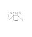
かかる問題を解消するための医療用コネクタの手動式脱着装置が下記特許文献1により提案されている。この手動脱着装置を用いた場合のコネクタの脱着手順を図18に概念的に示す。図18(a)は、患者側コネクタと透析液側コネクタを接続する前の準備段階を示し、まず、患者側300の腹腔に挿入されたカテーテルの先端には患者側コネクタ100が設けられ、コネクタキャップ101がされている。一方、透析側にはY字チューブの先端に透析液側コネクタ200が設けられ、コネクタキャップ201がされている。Y字チューブの二股に分岐した先には、透析液バッグ301と排液バッグ302が接続され、バルブによりいずれか一方が患者側と接続される。
図18(a)のセット状態では、患者側コネクタ100とコネクタキャップ201が並列配置されると共に、コネクタキャップ101と透析液側コネクタ200も並列配置される。 In the set state of FIG. 18A, the
このセット状態から、コネクタキャップ101と患者側コネクタ100を分離するために、コネクタキャップ101を回転させると共に両者を引き離す。これと同時に、コネクタキャップ201と透析液側コネクタ200を分離するために、透析液側コネクタ200を回転させると共に両者を引き離す。これを図18(b)に示す。 In order to separate the
次に、図18(c)に示すように、患者側コネクタ100とコネクタキャップ201を図の矢印方向にスライド移動させて、患者側コネクタ100と透析液側コネクタ200が互いに向かい合うようにする。ついで、図18(d)に示すように、患者側コネクタ100と透析液側コネクタ200を軸線方向に沿って移動させて接近させ、透析液側コネクタ200を回転することで、両者が連結される。この連結状態で、空の排液バッグ302に患者の腹腔内に貯留した透析液を排出する。そして、バルブを切り換えることで、透析液バッグ301内の透析液を腹腔内に注入する。 Next, as shown in FIG. 18C, the patient-
透析液の注入が終了すると、これまでとは逆の手順をたどり、再び、コネクタキャップを夫々のコネクタにかぶせる。この場合、コネクタキャップは新しいものを用意してセットしておく。 When the injection of dialysate is completed, the reverse procedure is followed, and the connector caps are put on the respective connectors again. In this case, a new connector cap is prepared and set.
以上のように、コネクタ同士を接続するまでに図18のような操作を行う必要があり、特許文献1では、ハンドル(操作部に相当)を180゜回転操作する場合に、この回転操作の領域の第1段階で(a)→(b)、第2段階で(b)→(c)、第3段階で(c)→(d)の操作を行なえるような機構が組み込まれている。 As described above, it is necessary to perform an operation as shown in FIG. 18 until the connectors are connected to each other. In
上記のような一連の作業を行うためには、まず最初に、患者側コネクタ100とコネクタキャップ101、透析液側コネクタ200とコネクタキャップ201を夫々所定のホルダに装着し、透析が終了すると、これらコネクタやコネクタキャップをホルダから取り外す必要がある。この取り外し作業は、患者自身の操作により行なわれるものであるが、患者の中には、眼や手の不自由な患者もいるため、必ずしも簡易な操作ではない。 In order to perform a series of operations as described above, first, the patient-
本発明は上記実情に鑑みてなされたものであり、その課題は、コネクタやコネクタキャップをホルダから取り出しやすくした医療用コネクタの手動式脱着装置を提供することである。 This invention is made | formed in view of the said situation, The subject is providing the manual detachment | desorption apparatus of the medical connector which made it easy to take out a connector and a connector cap from a holder.
上記課題を解決するため本発明に係る医療用コネクタの手動式脱着装置は、
第1コネクタと第2コネクタからなる医療用コネクタの脱着を行なうため、
第1コネクタに第1コネクタキャップが挿入された状態で、第1コネクタと第1コネクタキャップを夫々保持可能な第1コネクタホルダ及び第1キャップホルダと、
第2コネクタに第2コネクタキャップが挿入された状態で、第2コネクタと第2コネクタキャップを夫々保持可能な第2コネクタホルダ及び第2キャップホルダと、
を備えた医療用コネクタの手動式脱着装置であって、
第1コネクタ及び第1コネクタキャップを第1コネクタホルダ及び第1キャップホルダから取り出すための第1イジェクト手段と、
第2コネクタ及び第2コネクタキャップを第2コネクタホルダ及び第2キャップホルダから取り出すための第2イジェクト手段と、
第1イジェクト手段と第2イジェクト手段を作動させるためのイジェクト操作部と、
を備えていることを特徴とするものである。In order to solve the above problems, a manual connector for a medical connector according to the present invention comprises:
In order to attach and detach the medical connector composed of the first connector and the second connector,
A first connector holder and a first cap holder capable of holding the first connector and the first connector cap, respectively, with the first connector cap inserted into the first connector;
A second connector holder and a second cap holder capable of holding the second connector and the second connector cap, respectively, with the second connector cap inserted into the second connector;
A manual desorption device for a medical connector comprising:
First ejecting means for removing the first connector and the first connector cap from the first connector holder and the first cap holder;
A second ejecting means for removing the second connector and the second connector cap from the second connector holder and the second cap holder;
An eject operating section for operating the first ejecting means and the second ejecting means;
It is characterized by having.
この構成による医療用コネクタの手動式脱着装置の作用・効果を説明する。コネクタの脱着を行う場合には、第1コネクタに第1コネクタキャップが挿入された状態で、第1コネクタホルダ及び第1キャップホルダに装着する。また、第2コネクタに第2コネクタキャップが挿入された状態で、第2コネクタホルダ及び第2キャップホルダに装着する。また、第1イジェクト手段は、第1コネクタ及び第1コネクタキャップを夫々第1コネクタホルダ及び第1キャップホルダから取り出すことができる。第2イジェクト手段は、第2コネクタ及び第2コネクタキャップを夫々第2コネクタホルダ及び第2キャップホルダから取り出すことができる。イジェクト操作部を操作することで、これらイジェクト手段を作動させることで、各コネクタ及びコネクタキャップを取り出すことができる。これにより、例えば、身体の不自由な患者であっても、コネクタやコネクタキャップをホルダから容易に取り出すことができる。その結果、コネクタやコネクタキャップをホルダから取り出しやすくした医療用コネクタの手動式脱着装置を提供することができる。 The action and effect of the manual connector for the medical connector having this configuration will be described. When detaching the connector, the first connector holder and the first cap holder are mounted with the first connector cap inserted into the first connector. Moreover, it mounts | wears with a 2nd connector holder and a 2nd cap holder in the state in which the 2nd connector cap was inserted in the 2nd connector. The first ejecting means can take out the first connector and the first connector cap from the first connector holder and the first cap holder, respectively. The second ejecting means can take out the second connector and the second connector cap from the second connector holder and the second cap holder, respectively. Each connector and connector cap can be taken out by operating these ejection means by operating the ejection operation section. Thereby, for example, even a patient with a physical disability can easily take out the connector and the connector cap from the holder. As a result, it is possible to provide a medical connector manual attachment / detachment device in which the connector and the connector cap can be easily taken out from the holder.
本発明において、第1コネクタホルダと第1キャップホルダの少なくとも一方に、第1イジェクト手段を構成する突出部が突出するための穴を設けると共に、
第2コネクタホルダと第2キャップホルダの少なくとも一方にも、第2イジェクト手段を構成する突出部が突出するための穴を設け、
これら突出部によりコネクタやコネクタキャップを上方に押し出すように構成したことを特徴とするものである。In the present invention, at least one of the first connector holder and the first cap holder is provided with a hole for projecting the projecting portion constituting the first ejecting means,
At least one of the second connector holder and the second cap holder is provided with a hole for projecting the projecting portion constituting the second ejecting means,
These protrusions are configured to push out the connector and the connector cap upward.
この構成によると、コネクタやコネクタキャップのいずれか一方もしくは両方が突出部により上方に押し出されるように構成されている。これにより、コネクタやコネクタキャップをホルダから取り出しやすい状態にすることができる。 According to this configuration, one or both of the connector and the connector cap are configured to be pushed upward by the protruding portion. As a result, the connector and the connector cap can be easily removed from the holder.
本発明において、第1イジェクト手段を構成する第1突出部及び第2突出部と、
第2イジェクト手段を構成する第3突出部及び第4突出部と、
第1コネクタホルダと第1キャップホルダの夫々に形成され、第1突出部及び第2突出部が突出するための穴と、
第2コネクタホルダと第2キャップホルダの夫々に形成され、第3突出部及び第4突出部が突出するための穴と、を備えていることが好ましい。In the present invention, a first projecting portion and a second projecting portion constituting the first ejecting means,
A third protrusion and a fourth protrusion constituting the second ejecting means;
A hole formed in each of the first connector holder and the first cap holder, through which the first protrusion and the second protrusion protrude;
It is preferable that each of the second connector holder and the second cap holder is provided with a hole through which the third protrusion and the fourth protrusion protrude.
この構成によると、第1コネクタと第1コネクタキャップは、第1イジェクト手段の第1突出部と第2突出部により押し上げられる。第2コネクタと第2コネクタキャップは、第2イジェクト手段の第3突出部と第4突出部により押し上げられる。これにより、確実にコネクタとコネクタキャップの両方をホルダから脱出させることができる。 According to this configuration, the first connector and the first connector cap are pushed up by the first projecting portion and the second projecting portion of the first ejecting means. The second connector and the second connector cap are pushed up by the third protrusion and the fourth protrusion of the second ejecting means. Thereby, both a connector and a connector cap can be reliably escaped from a holder.
本発明において、イジェクト操作部と、このイジェクト操作部の動きを第1イジェクト手段及び第2イジェクト手段に伝達するための伝達部材を備えたことが好ましい。 In the present invention, it is preferable that an ejection operation unit and a transmission member for transmitting the movement of the ejection operation unit to the first ejection unit and the second ejection unit are provided.
この構成によると、イジェクト操作部を操作することで、その動きが伝達部材を介して第1イジェクト手段と第2イジェクト手段の両方に伝達されるため、効率よく全てのコネクタとコネクタキャップをホルダから脱出させることができる。 According to this configuration, since the movement is transmitted to both the first ejecting means and the second ejecting means via the transmission member by operating the eject operation unit, all the connectors and connector caps are efficiently removed from the holder. You can escape.
本発明に係る医療用コネクタの手動式脱着装置の好適な実施形態を図面を用いて説明する。まず、医療用コネクタの好適な実施形態を説明する。 A preferred embodiment of a manual connector for a medical connector according to the present invention will be described with reference to the drawings. First, a preferred embodiment of the medical connector will be described.
<医療用コネクタ>
冒頭で説明したように、本発明に係る医療用コネクタは、好適には腹膜透析法(CAPD)で使用されるものであり、患者側コネクタと透析液側コネクタにより構成される。これらコネクタの構成を図1に示す。<Medical connector>
As explained at the beginning, the medical connector according to the present invention is preferably used in peritoneal dialysis (CAPD), and is composed of a patient side connector and a dialysate side connector. The structure of these connectors is shown in FIG.
図1(a)は、患者側の第1コネクタ1の構成を示している。第1コネクタ1は、チューブ10の先端側にコネクタ接続部11が設けられる。コネクタ接続部11における接続操作を行なうためのつまみ部12と、つまみ部12とコネクタ接続部11の境界に位置するフランジ13が設けられる。コネクタ接続部11には、Oリング14とカム溝15が設けられている。Oリング14を設けることで、透析液の漏洩などを防止する。つまみ部12には、円周方向に2箇所、操作用の突出部12aが設けられる。 FIG. 1A shows the configuration of the
カム溝15を円周方向に沿って展開すると、図1(b)に示すような図になる。カム溝15は、円周方向に同じものが180゜間隔で2箇所形成されている。カム溝15は、第1領域15aと第2領域15bを有し、第1領域15aは円周方向で45゜の領域を占め、傾斜した溝となっている。第2領域15bも円周方向で45゜の領域を占め、円周方向に沿った直線溝となっている。 When the
コネクタ接続部11には、第1コネクタキャップ3を被せることができ、操作用の突出部30が円周方向に2箇所設けられている。第1コネクタキャップ3の内部には、2箇所、カム溝15に係合する係合突起31が設けられている。従って、第1コネクタキャップ3を第1コネクタに被せるときは、係合突起31をカム溝15の入口のところに合わせ(図1(b)参照)、第1コネクタキャップ3を回転させることで(第1コネクタ1側を回転させてもよい)、第1コネクタキャップ3が回転すると共に、軸線方向(図1の左右方向)に移動し、第1コネクタ1に第1コネクタキャップ3を被せることができる。図2(a)は第1コネクタ1と第1コネクタキャップ3の結合完了状態を示している。 The
また、第1コネクタキャップ3の外周面にはリング状の第1フランジ30aと第2フランジ30bが形成されており、第1キャップホルダに装着した時の位置決めに利用される。第1フランジ30aと第2フランジ30bは、ホルダへの位置決めを行なうために所定間隔離れており、第2フランジ30bが挿入側に位置する。 Further, a ring-shaped
図1(c)は、透析液側の第2コネクタ2の構成を示している。第2コネクタ2は、Y字チューブ20の先端側にコネクタ接続部21が設けられる。Y字チューブ20には、排液バッグと透析液バッグが接続される。コネクタ接続部21には、円周方向に2箇所、操作用の突出部21aが形成される。また、コネクタ接続部21の外周には、リング状の第1フランジ21bと第2フランジ21cが設けられており、第2コネクタホルダに装着した時の位置決めに利用される。第1フランジ21bと第2フランジ21cは、ホルダへの位置決めを行なうために所定間隔は慣れており、第2フランジ21cが挿入側に位置する。 FIG. 1C shows the configuration of the
コネクタ接続部21には、第2コネクタキャップ4を被せることができる。第2コネクタキャップ4には、つまみ部40が設けられ、このつまみ部40の円周方向2箇所には操作用の突出部40aが形成されている。第2コネクタキャップ4の先端には、コネクタ接続部21と連結させるための係合爪41が2箇所設けられている。 The
図2(b)は、第2コネクタ2と第2コネクタキャップ4を結合した状態を示すが、コネクタ接続部21の内部には、係合爪41の先端が係合する係合溝22が設けられている。従って、第2コネクタ2と第2コネクタキャップ4を結合するときは、第2コネクタ2の係合溝22と、第2コネクタキャップ4の係合爪41の円周方向の位置を合わせ、そのまま軸線方向に沿って第2コネクタキャップ4を挿入することで結合できる。すなわち、第2コネクタ2と第2コネクタキャップ4の結合に際して、回転操作は不要であり、軸線方向の移動のみで着脱可能である。 FIG. 2B shows a state in which the
透析液の交換を行なうときには、患者側の第1コネクタ1の第1コネクタキャップ3を外すと共に、透析液側の第2コネクタ2の第2コネクタキャップ4も外し、第1コネクタ1と第2コネクタ2を連結する。その接続完了状態を図2(c)に示す。第2コネクタ2のコネクタ接続部21の内部にも、第1コネクタキャップ3と同様に係合突起23が設けられており、カム溝15に係合することができる。よって、第2コネクタ2を第1コネクタ1に装着するときの動作は、第1コネクタキャップ3を装着するときの動作(回転操作+軸線方向の移動)と同じである。 When exchanging the dialysate, the
また、第1コネクタキャップ3と第2コネクタキャップ4も互いに装着することができる。第1コネクタキャップ3の内部には、第2コネクタと同様に、第2コネクタキャップ4の係合爪41と係合する係合溝32が設けられている。第1・第2コネクタキャップ3,4を結合するときは、回転操作は不要であり、軸線方向のみの操作でよい。 The
患者側の第1コネクタ1は、透析液の交換時(排出・注入時)において透析液バッグと接続する必要があると共に、次回の透析液の交換までの間に、第1コネクタ1の結合状態が不用意に外れないように保護する必要がある。そこで、第1コネクタ1と第2コネクタ2、及び、第1コネクタ1と第1コネクタキャップ3の脱着操作は、回転操作によるものとした。 The
また、透析液側の第2コネクタ2の方は、製品の外包材を開封して、患者側の第1コネクタ1と接続するまでの間、保護されていればよく、回転操作による脱着は必要ないため、第2コネクタ2と第2コネクタキャップ4の脱着操作は軸線方向の移動のみとしている。 In addition, the
<医療用コネクタの手動式脱着装置の構成>
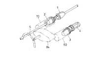
次に、図1,図2で説明した医療用コネクタの手動脱着装置について説明する。図3は、手動脱着装置の外観構成を示す斜視図であり、図4は、手動脱着装置の開閉蓋を開いた状態を示す斜視図である。図5は、手動脱着装置の開閉蓋を開いた状態を示す平面図である。<Configuration of manual connector for medical connector>
Next, the manual attachment / detachment device for the medical connector described in FIGS. 1 and 2 will be described. FIG. 3 is a perspective view showing an external configuration of the manual detaching device, and FIG. 4 is a perspective view showing a state in which an opening / closing lid of the manual detaching device is opened. FIG. 5 is a plan view showing a state where the open / close lid of the manual detaching device is opened.
手動脱着装置は、外観部品として、本体ケース5と開閉蓋6を備えている。開閉蓋6は、回転軸芯である軸線X1周りに回転可能に軸支されており、開閉蓋6を開くことにより装置本体上部が露出するように構成される。本体ケース5の側面部に形成された湾曲部5aと、開閉蓋6の側面部に形成された湾曲部6aにより、開閉蓋6を閉じた時にスリットSが形成される。このスリットSは、第1コネクタ1と第2コネクタ2の脱着を行う時に、第2コネクタ2のY字チューブ20が移動できるように設けられたものである。このスリットSは、ほぼ円弧状に形成されている。The manual attachment / detachment device includes a
本体ケース5の前面側には、回転ハンドル形式の操作部7が設けられており、軸芯Y周りに145゜回転操作できるように取り付けられている。操作部7の端部には操作つまみ7aが設けられており、開閉蓋6を閉じて矢印A1方向に操作部7を回転させることで第1コネクタ1と第2コネクタ2の結合を行なうことができ、矢印B1方向に回転させることで、第1コネクタ2と第2コネクタ2の分離を行なうことができる。また、操作部7は、開閉蓋6を開いた状態では回転操作できないようにロック機構が設けられている。On the front side of the
<ホルダ構造>
次に、第1コネクタ1と第2コネクタ2をセットするためのホルダ構造に関して説明する。コネクタ1,2をセットするための各ホルダは、開閉蓋6を開くことで装置本体上部に露出するため、上方から各コネクタ1,2をセットすることができる。<Holder structure>
Next, a holder structure for setting the
図6は、第1コネクタ1をセットするためのホルダ構造を示し、図7は、第2コネクタ2をセットするためのホルダ構造を示す。図8は、開閉蓋を内側から見た図を示す。 6 shows a holder structure for setting the
図6において、(a)は第1コネクタ1を保持するためのホルダ構造を示す斜視図、(b)は平面図、(c)は側面図、(d)は第1コネクタ1を装着した状態を示している。第1コネクタホルダ50には、第1コネクタキャップ3を結合した状態で第1コネクタ1を装着することができる。第1コネクタホルダ50は、ホルダ本体部50aと、ホルダ本体部50aと一体的に設けられるチューブ支持部50bを備えている。また、ホルダ本体部50aの中央には弾性変形可能な係合爪50cが一体形成されている。第1コネクタ1のつまみ部12がホルダ本体部50aに挿入されると、係合爪50cによりつまみ部12を弾性的に挟持し、装着された第1コネクタ1が第1コネクタホルダ50内で回転しないように保持される。図6(b)に示すように、ホルダ本体部50aの底部には溝50dが形成されており、第1コネクタ1の突出部12aがこの溝50dに挿入され、第1コネクタホルダ50内での第1コネクタ1の回転を確実に阻止する。 6A is a perspective view showing a holder structure for holding the
また、補助ホルダ51が設けられており、その内部にチューブ支持部50bが矢印C方向にスライド可能に挿入される。圧縮コイルスプリング52が設けられており、第1コネクタホルダ50が突出する方向に付勢されている。チューブ支持部50bには、第1コネクタ1のチューブ10が挿入できるようにチューブ収容溝50e(U字形)が設けられており、補助ホルダ51には、チューブ10が挿入可能なように上部にスリットが設けられる。 Moreover, the
ホルダ本体部50aの底部には穴50fが形成されており、不図示のイジェクトピンがこの穴50fを介して突出可能に構成されており、一度装着した第1コネクタ1を取り出しやすくしている。なお、イジェクト機構については、後述する。 A
第1キャップホルダ60は、第1コネクタキャップ3が装着される。第1コネクタキャップ3は、第1コネクタホルダ50に近い側に位置する第1本体部60aと、遠い側に位置する第2本体部60bを備えており、更に、これら本体部60a,60bの間にスリット60cが形成される。第1本体部60aは、その上方から第1コネクタキャップ3を装着できるように上部が開放され、第2本体部60bも一部上部が開放されている。 The
第1キャップホルダ60の底部には軸線方向に沿った溝60dが形成され、第1コネクタキャップ3の突出部30が嵌合し、これにより、第1コネクタキャップ3が第1キャップホルダ60内で相対的に回転しないように保持される。また、第1本体部60aの内部には円周溝60eが形成され、第1コネクタキャップ3の第1フランジ30aが嵌入され、第1コネクタキャップ3をその軸線方向に位置決めした状態で取り付け可能にしている。 A
第1本体部60aの底部には穴60fが形成され、第1コネクタホルダ50と同様に不図示のイジェクトピンが突出可能に構成される。 A
第2本体部60bの第1本体部60aとは反対側に、リング状のガイド溝61が形成され、更に、第1ギヤ62が設けられる。第1ギヤ62と一体的にギヤ軸62aが設けられており、このギヤ軸62aの軸芯は、第1コネクタ1の軸線とは偏心した位置にある。ガイド溝61や第1ギヤ62の機能については後述する。 A ring-shaped
図8Aは、開閉蓋6を内側からみた構成を示す斜視図であり、図8Bは同じく側面図である。先ほど説明した第1コネクタホルダ50と補助ホルダ51は、開閉蓋6の回転軸芯の軸線X1と同軸の位置に取り付けられる。従って、開閉蓋6を開閉のために回転させると、これに連動して同じ角度だけ第1コネクタホルダ50と補助ホルダ51も回転する。かかる構成を採用することで、開閉蓋6の開閉操作に連動して、第1コネクタ1を回転させて第1コネクタキャップ3を緩めること、あるいは、ネジ締結することができる。FIG. 8A is a perspective view showing the configuration of the opening /
第1キャップホルダ60は、装置本体側に設けられることになるが、軸線X1と同軸になる位置に設けられる。The
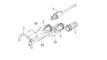
図7において、(a)は第2コネクタ2を保持するためのホルダ構造を示す斜視図、(b)は平面図、(c)は側面図、(d)は第2コネクタ2を装着した状態を示している。第2コネクタホルダ70には、第2コネクタキャップ4を結合した状態で第1コネクタ2を装着することができる。 7A is a perspective view showing a holder structure for holding the
第2コネクタホルダ70は、第2キャップホルダ45に近い側に位置する第1本体部70aと、遠い側に位置する第2本体部70bと、第1本体部70aと第2本体部70bの間に形成されるスリット70cを備えている。第1本体部70aは、上方から第2コネクタ2を挿入するために上部が開放され、第2本体部70bも同様に上部が開放されている。 The
第2コネクタホルダ70の底部には軸線方向に沿った溝70dが形成され、第2コネクタ2の突出部21aが嵌合し、これにより、第2コネクタ2が第2コネクタホルダ70内で相対的に回転しないように保持される。また、第1本体部70aの内部には円周溝70eが形成され、第2コネクタ2の第1フランジ21bが嵌入され、第2コネクタ2をその軸線方向に位置決めした状態で取り付け可能にしている。 A
第2本体部70bの第1本体部70aとは反対側に、リング状のガイド溝71が形成され、更に、第2ギヤ72が設けられる。第2ギヤ72と一体的にギヤ軸72aが設けられており、このギヤ軸72aの軸芯は、第2コネクタ2の軸線とは偏心した位置にある。ガイド溝71や第1ギヤ72の機能については後述する。ガイド溝71が形成されている部分の上方には、第2コネクタ2のY字チューブ20が挿入可能なように、チューブ20の幅に対応したスリット70gが形成されている。 A ring-shaped
ホルダ本体部70aの底部には穴70fが形成されており、不図示のイジェクトピンがこの穴70fを介して突出可能に構成されており、一度装着した第2コネクタ2を取り出しやすくしている。 A
第2キャップホルダ45は、係合爪45aを備えており、第2コネクタキャップ4のつまみ部40を弾性的に挟持する。また、軸線方向に沿って形成される溝45bを備えており、第2コネクタキャップ4の突出部40aが嵌合する。これにより、第2コネクタキャップ45が第2キャップホルダ45内で相対的に回転しないように保持される。 The
第2コネクタホルダ70及び第2キャップホルダ45の軸線X2は、隣接配置される第1コネクタホルダ50及び第1キャップホルダ60の軸線X1と平行であり、かつ所定間隔離れて配置される。The axis X2 of the
また、第2キャップホルダ45は、回転も移動もできない状態で装置本体上部に固定される。第2キャップホルダ45の底部には結合用の爪45cが一体形成されており、この爪45cを利用して装置本体に対して結合される。 Further, the
第2キャップホルダ45の底部にも穴45dが形成されており、不図示のイジェクトピンがこの穴45dを介して突出可能に構成されており、一度装着した第2コネクタキャップ4を取り出しやすくしている。 A
<内部機構の説明>
操作部7は、手動による回転操作により回転する部材であり、図1の矢印A1方向に操作すると、第1コネクタ1と第2コネクタ2のコネクタキャップ3,4を夫々外して、第1コネクタ1と第2コネクタ2を連結させることができる。同時に、各コネクタ1,2のコネクタキャップ3,4同士も連結させることができる。<Description of internal mechanism>
操作部7を矢印B1方向に操作すると、先ほどとは逆の動作が行なわれ、第1コネクタ1と第2コネクタ2を分離させ、新しいコネクタキャップ3,4を夫々のコネクタ1,2に装着させることができる。When the
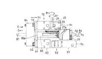
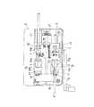
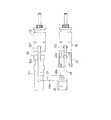
図9A〜図9Dは、上記脱着を行なうためのホルダ駆動機構を示す図である。図9Aは、ホルダ駆動機構を底面側から見た図である。ホルダ駆動機構を上方から見た図は、図5に一部示されている。図9Bは、斜め下方から見た斜視図である。図9Cは、軸線方向の一方から見た図であり、図9Dは軸線方向の他方から見た図である。 9A to 9D are views showing a holder driving mechanism for performing the above-described attachment / detachment. FIG. 9A is a view of the holder driving mechanism as seen from the bottom surface side. A view of the holder driving mechanism as viewed from above is partially shown in FIG. FIG. 9B is a perspective view seen from obliquely below. FIG. 9C is a view seen from one side in the axial direction, and FIG. 9D is a view seen from the other side in the axial direction.
図9において、操作軸25は、操作部7に連結されており、操作部7の回転操作に連動して回転する。この操作軸25に、ベベルギヤ26が一体結合されている。また、軸線X1とX2のちょうど中点に軸線X3が設定されており、この軸線X3周りに回転可能な円筒カム27が設けられる。円筒カム27の円周面に沿ってカム溝27aが形成されている。In FIG. 9, the
また、円筒カム27と一体回転可能に取り付けられたベベルギヤ28と部分ギヤ29が設けられている。ベベルギヤ28は、ベベルギヤ26と回転軸芯が直交する状態で噛み合っており、従って、操作部7を回転すると、円筒カム27と共にベベルギヤ28と部分ギヤ29も一緒に回転する。ベベルギヤ26、円筒カム27、ベベルギヤ28、部分ギヤ29は、回転はできるが軸線方向に沿って移動することはできない。 Further, a
ホルダ支持体80は、本体ケース5に取り付けられる駆動軸81に対して軸線方向X3に沿って移動可能に構成される。ホルダ支持体80には、カム溝27aに係合するカムピン(図には表れていない)が植設されている。従って、円筒カム27を回転することで、カムピンがカム溝27aに沿って移動するため、ホルダ支持体80が軸線にX3沿って移動可能になる。ただし、ホルダ支持体80は軸線X3周りに回転することはできない。The
ホルダ支持体80の軸線方向の一端部にはガイド体80aが一体的に設けられており、このガイド体80aがガイド溝61,71に嵌合している。これにより、第1キャップホルダ60と第2コネクタホルダ70は、軸線X3周りにスムーズに回転可能となっている。A
駆動軸81は、その両端部が装置本体に回転可能な状態で軸支されている。この駆動軸81の一端部には、連結ギヤ81aが結合されており、この連結ギヤ81aは部分ギヤ29と噛み合うことができる。部分ギヤ29は、図9Cに示すように、全周に歯がなく、円周方向の一部の領域のみにギヤ形成部29aが設けられている。連結ギヤ81aは、軸線X3に沿って移動できるため、部分ギヤ29と連結ギヤ81aが軸線方向で同じ位置にあるときにのみ、連結ギヤ81aと部分ギヤ29が噛み合うことができる。The
駆動軸81の他端側には、ガイド体80aに隣接して駆動ギヤ81bが結合されている。これにより、部分ギヤ29と噛み合った連結ギヤ81aが回転すると、駆動ギヤ81bも一緒に回転できる。 A
図9Dは、一部の部品(ギヤホルダ84など)を除去した状態で図示しているが、駆動ギヤ81bは第1ギヤ62と第1中間ギヤ82を介して連結され、第2ギヤ72とは第2中間ギヤ83を介して連結される。また、図9Bにも示すように、ギヤホルダ84が設けられており、駆動軸81に対して一体的に結合されると共に、第1ギヤ62のギヤ軸62a、第2ギヤ72のギヤ軸72a、第1中間ギヤ82、第2中間ギヤ83を軸支している。これらギヤホルダ84により支持される5枚のギヤを説明の便宜上ギヤユニットと称する。 FIG. 9D shows a state in which some parts (such as the gear holder 84) are removed, but the
かかる構成によれば、駆動軸81が回転すると、ギヤホルダ84も回転するため、軸線周りに第1キャップホルダ60と第2コネクタホルダ70が回転する。回転角度は180゜になるように設定されている。また、ギヤユニットを設けているため、第1キャップホルダ60と第2コネクタホルダ70は、その支持姿勢を変えないまま(第1コネクタキャップ3と第2コネクタ4が上方に位置したまま)180゜回転させられることになる。 According to this configuration, when the
<ロック機構>
次に、開閉蓋6のロック機構と操作部7のロック機構について図10により説明する。図10(a)は開閉蓋6に取り付けられているロック機構の一部を示す平面図であり、図10(b)は、ロック機構の構成を示す側面図である。<Lock mechanism>
Next, the locking mechanism of the opening /
開閉蓋6側にはロックレバー90が水平方向にスライド移動可能に取り付けられており、図10(b)はロックした状態を示している。ロックレバー90には、係合爪90aが一体形成されており、本体ケース5側に設けられた被係合部5bに係合することで開閉蓋6の開放を阻止する。 A
本体ケース5側には、中継レバー91と操作ロック部材92が設けられている。中継レバー91は軸芯91a周りに揺動可能に軸支されている。操作ロック部材92は垂直方向にスライド移動可能であり、スプリング93により垂直下方向に付勢されている。スプリング93は、操作ロック部材92上に植設されたピン92aと、本体ケース5の操作部に植設されたバネ支持ピン5cの間に引っ掛けられている。また、中継レバー91と操作ロック部材92は、連動して動作するように結合されている。 A
操作部7の操作軸25に連結されたロック板94には、2つの係合溝94a,94bが形成されている。これら係合溝94a,94bに、操作ロック部材92の係合突起92bが係合可能に構成される。この2つの係合溝94a,94bは、操作部7の操作角度(145゜)に対応して形成されている。 Two
図10(c)は、開閉蓋6を開いた状態を示しており、ロックレバー90の係合爪90aが上方に退避しているため、中継レバー91はフリーの状態となる。そのため、スプリング93の付勢力により、操作ロック部材92は下方向に付勢されて、係合突起92bがいずれかの係合溝94a,94bに係合可能になる。これにより、開閉蓋6が開いた状態で、操作部7が操作されることを禁止する。 FIG. 10C shows a state in which the opening /
また、操作部7による操作を行なっている間は、係合突起92bがロック板94の外周面94cに位置し、これにより、開閉蓋6のロックレバー90のスライド移動が阻止される。従って、操作中は開閉蓋6が不用意に開かないように構成されている。 Further, while the operation by the
操作部7は、第1位置から第2位置へと回転操作可能であり、その間の操作角度は145゜である。また、操作部7の回転操作に連動して内部の円筒カム27が回転するが、円筒カム27に形成されるカム溝の角度はトータルで300゜となっている。図11は、カム溝27aを展開して示す図である。操作部7及び円筒カム27の操作領域は、第1操作領域S1、第2操作領域S2,第3操作領域S3の3つの領域に分けることができる。角度配分は、S1=S3=105゜,S2=90゜である。 The
操作部7の往動作において、第1操作領域S1は、第1コネクタ1と第1コネクタキャップ3、第2コネクタ2と第2コネクタキャップ4を夫々引き離す工程、第2操作領域S2は、引き離された第1コネクタキャップ3と第2コネクタ2を軸線X3周りに180゜回転させる工程、第3領域操作S3は、第1コネクタ1と第2コネクタ2、第1コネクタキャップ3と第2コネクタキャップ4をそれぞれ近接させる工程である。操作部7の復動作においては、上記とは逆の工程が行なわれる。In the forward operation of the
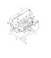
<イジェクト機構>
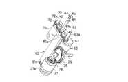
次に、イジェクト機構を図17及び図5により説明する。イジェクト機構は、第1コネクタキャップ3が装着された第1コネクタ1や、第2コネクタキャップ4がされた第2コネクタ2をホルダから取り出しやすくするための機構である。ホルダに装着された各コネクタ1,2やコネクタキャップ3,4は、手で引っ張りあげることでホルダから脱出させることができる。しかし、患者の中には、眼や手の不自由な患者もいるため、かかる操作は必ずしも簡易な操作ではない。そこで、イジェクト機構を設けることで、コネクタやコネクタキャップの取り出しを容易にしている。<Eject mechanism>
Next, the ejection mechanism will be described with reference to FIGS. The eject mechanism is a mechanism for facilitating removal of the
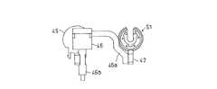
図17Aは、イジェクト機構をホルダの下部から見た斜視図である。図17Bは、イジェクト機構をホルダの下部から見た底面図である。図17Cは、イジェクト機構を軸線方向から見た図である。 FIG. 17A is a perspective view of the eject mechanism as viewed from the bottom of the holder. FIG. 17B is a bottom view of the eject mechanism as viewed from the bottom of the holder. FIG. 17C is a diagram of the ejection mechanism as viewed from the axial direction.
手動操作を行なうための操作ボタン46が設けられており、下方に押すことができる。この操作ボタン46は、不図示のバネにより、常時、上方向に付勢されている。この操作ボタン46は、第1伝達部材46aと第2伝達部材46bが一体的に形成されている。第1伝達部材46aには、支持軸46cにより第1イジェクト部材47(第1イジェクト手段に相当)が軸支されている。第2伝達部材46bには、支持軸46dにより第2イジェクト部材48(第2イジェクト手段に相当)が軸支されている。 An
第1伝達部材47には、第1突出部47aと第2突出部47b(これらはイジェクトピンに相当)が一体形成され、夫々、第1コネクタホルダ50に形成された穴50fと第1キャップホルダ60に形成された穴60fに出退可能である。また、第1伝達部材47は回転軸芯47c周りに回転可能である。従って、支持軸46cにおいても、この回転を許容できるような形で軸支される。 The
第1伝達部材48には、第3突出部48aと第4突出部48b(これらはイジェクトピンに相当)が一体形成され、夫々、第2コネクタホルダ70に形成された穴70fと第2キャップホルダ45に形成された穴45dに出退可能である。また、第1伝達部材48は回転軸芯48c周りに回転可能である。従って、支持軸46dにおいても、この回転を許容できるような形で軸支される。 The
次に、イジェクト機構の動作を説明する。操作ボタン46を押圧すると、第1イジェクト部材47と第2イジェクト部材48は、同時に、回転軸芯47c,48c周りに回転する。これにより、第1突出部47aと第2突出部47bは、第1コネクタホルダ50及び第1キャップホルダ60内に突出する。この動作と同時に、第3突出部48aと第4突出部48bは、第2コネクタホルダ70及び第2キャップホルダ45内に突出する。この状態を図17Dに示す。これにより、第1コネクタ1や第2コネクタ2などを容易にホルダから取り出すことができる。 Next, the operation of the ejection mechanism will be described. When the
<コネクタの着脱操作>
次に、本実施形態に係る医療用コネクタの手動式脱着装置によるコネクタの着脱操作について、図12に基づいて説明する。<Connecting / detaching connector>
Next, a connector attaching / detaching operation using the medical connector manual attachment / detachment device according to the present embodiment will be described with reference to FIG.
<1.コネクタのセット→蓋閉鎖>
まず、手動脱着装置の開閉蓋6を開放する。開閉蓋6の開放角度はちょうど90゜の状態である。図5に示す状態において、第1コネクタキャップ3が結合された第1コネクタ1をそれぞれ第1キャップホルダ60と第1コネクタホルダ50に装着する。一方、第2コネクタキャップ4が結合された第2コネクタ2を夫々第2キャップホルダ45と第2コネクタホルダ70に装着する(図12A参照)。このとき、操作部7は第1位置にあり、開閉蓋6が開いているため、ロック機構により動かないようにロックされている。<1. Connector set → lid closure>
First, the opening /
次に、開閉蓋6を閉鎖していくと、開閉蓋6は軸線X1周りに回転する。これに伴い、第1コネクタホルダ50及び補助ホルダ51も軸線X1周りに回転する。回転角度は開閉蓋6と同じであり、開閉蓋6を閉めるまでに第1コネクタホルダ50及び補助ホルダ51は90゜回転する。従って、これに装着された第1コネクタ1が90゜回転する。Next, when the opening /
第1コネクタ1を90゜回転させていくと、第1コネクタ1と第1コネクタキャップ3の結合が緩み始め、図1で示したように、コネクタキャップ3の係合突起31が第1コネクタ1のカム溝15から離脱する。この時、第1コネクタ1は軸線X1に沿って第1コネクタキャップ3から離間しようとするため、第1コネクタホルダ50は圧縮コイルスプリング52の付勢力に抗して後退する。これにより、第1コネクタ1から第1コネクタキャップ3を引き離す準備が整ったことになる。When the
また、開閉蓋6を閉じると、ロックレバー90の係合爪90aが中継レバー91を下方に押して中継レバー91を回転させる。これにより、操作ロック部材92が上方にスライド移動させられ、係合突起92bがロック板94の係合溝94bから離脱する。これにより、操作部7を回転操作できる状態になる。また、ロックレバー90をスライドさせて、開閉蓋6が不用意に開放しないようにする。 When the opening /
<2.第1操作領域>
次に、操作部7を第1位置から徐々に回転させていく(矢印A1方向)。操作部7の回転により操作軸25及びベベルギヤ26が回転する。ベベルギヤ26の回転は、これに噛み合うベベルギヤ28に伝達され、円筒カム27を回転させる。円筒カム27の回転により、カム溝27aに係合しているホルダ支持体80のカムピンがカム溝27aに沿って移動する。<2. First operation area>
Next, the
これにより、ホルダ支持体80が軸線X3に沿って矢印D方向に移動する(図9A、図13(a)参照)。この移動に伴い、第1キャップホルダ60と第2コネクタホルダ70も同じ方向に移動する。また、連結ギヤ81aも同じ方向に移動する。ギヤホルダ84に支持されるギヤユニットも同じ方向に移動する。Thus, the
この移動により、第1コネクタ1と第1コネクタキャップ3は互いに引き離されていくことになる。第1コネクタ1と第1コネクタキャップ3は、予めネジ結合を緩めており、スムーズに両者を引き離すことができる。これと同時に、第2コネクタ2と第2コネクタキャップ4も互いに引き離される。第2コネクタ2と第2コネクタキャップ4はネジ結合ではなく、第2コネクタ2を矢印D方向に単に移動させることで、係合爪41が係合溝32から離脱し(図2(d)参照)、両者を分離させることができる。図12Bは、その時の状態を示す平面図である。 By this movement, the
図13は、第1操作領域S1における内部機構の動きを説明する図であり、図13(a)は下方から見た斜視図、(b)は軸線方向視の図である。図9Dは操作部7による操作を開始する前(第1位置)の状態であり、部分ギヤ29と連結ギヤ81aは、軸線X3方向においてずれた位置にあるが、カム溝27aとカムピンの作用によりホルダ支持体80が軸線X3方向(矢印D方向)に移動することで、連結ギヤ81aが連結ギヤ29の方向に近づいてくる。図13は、第1操作領域S1の操作完了状態を示しており、軸線X3方向において、連結ギヤ81aと連結ギヤ29がちょうど同じ位置になる。13A and 13B are views for explaining the movement of the internal mechanism in the first operation region S1, FIG. 13A is a perspective view seen from below, and FIG. 13B is a view in the axial direction. Figure 9D is a state before (first position) to start the operation by the
更に、部分ギヤ29aが回転していき、第1操作領域S1の終了時では、部分ギヤ29aが連結ギヤ81aに噛み合う直前の状態となる(図13(b)参照)。この時、円筒カム27は105゜回転した状態である(図11のカム線図参照)。 Further, the
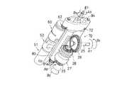
<3.第2操作領域>
更に、操作部7を回転させていくと第2操作領域S2へと入る。この時、連結ギヤ81aと連結ギヤ29が噛み合うため、連結ギヤ81aが回転させられる。これに連動して、駆動軸81及びギヤホルダ84も回転する。この時の様子を図14に示す。<3. Second operation area>
Furthermore, if the
ギヤホルダ84は軸線X3周りに矢印A3方向に回転する。また、第2操作領域S2では、ホルダ支持体80のカムピンが係合するカム溝27aは、変位の変動がないため(図11参照)、ホルダ支持体80は軸線X3方向に沿って移動せず、停止した状態となる。ギヤホルダ84の回転に伴い、それに支持される第1キャップホルダ60と第2コネクタホルダ70も共に同じ方向に回転する。これにより、第1コネクタキャップ3と第2コネクタ2が軸線X3周りに回転させられる。図14A(下方から見た斜視図),14B(上方から見た斜視図)は回転動作の途中を示している。
また、駆動軸81の回転により駆動ギヤ81bも回転するので、第1・第2中間ギヤ82,83を介して、第1ギヤ62と第2ギヤ72も回転する。この第1ギヤ62と第2ギヤ72の回転により、第1キャップホルダ60と第2コネクタホルダ70は、軸線X3周りに回転しながら、同時にギヤ軸62a,72a周りにも自転する。これにより、第1キャップホルダ60と第2コネクタホルダ70は、同じ水平姿勢を維持しながら回転することになり、第1コネクタキャップ3と第2コネクタ2も最初に装着したときの姿勢を維持しながら回転させられる。Further, since the
また、第2コネクタ2の回転によりこれに連結されたY字チューブ20も一緒に回転するが、図1で説明したように、本体ケース5と開閉蓋6には円弧状のスリットSが形成されており、このスリットSに沿ってY字チューブ20が移動することができる。これにより、第2コネクタ2の移動を支障なく行なうことができる。 In addition, the Y-shaped
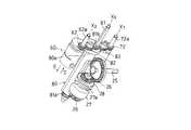
図15A,Bは、第2操作領域S2における操作を完了した状態を示しており、ギヤホルダ84などが180゜回転した状態である。この時、第2コネクタホルダ70と第1コネクタホルダ50が向かい合っており、第1キャップホルダ60と第2キャップホルダ45が向かい合っている。これにより、第1コネクタ1と第2コネクタ2を連結する準備と、第1コネクタキャップ3と第2コネクタキャップ4を連結する準備が整ったことになる。 15A and 15B show a state in which the operation in the second operation region S2 is completed, and is a state in which the
<3.第3操作領域>
更に、操作部7を回転していくと、第3操作領域S3へと入る。この時、部分ギヤ29のギヤ形成部29aは、連結ギヤ81aとの噛み合いから外れる。従って、これ以上連結ギヤ81aは回転することはなく、ギヤホルダ84や駆動ギヤ81bなどの回転も停止する。<3. Third operation area>
Furthermore, if the
また、ホルダ支持体80のカムピンは円筒カム27のカム溝27aの第3操作領域S3に係合することになり、これに伴い、ホルダ支持体80は軸線X3に沿って矢印E方向に移動する。この移動方向は、第1操作領域S1における方向Dと全く逆である。ホルダ支持体80の移動と共に、第1キャップホルダ60と第2コネクタホルダ70も軸線X3に沿って移動する。従って、第2コネクタ2は第1コネクタ1の方向に近づいていき、第1コネクタキャップ3は第2コネクタキャップ4の方向に近づいていく。The movement, the cam pin of the
第3操作領域S3における操作が完了した状態を図16の平面図に示す。第1コネクタ1が第2コネクタ2に挿入された状態となっている。この時、第2コネクタ2の係合突起23が、第1コネクタ1のカム溝15に挿入可能な状態となっている。従って、この段階では第1コネクタ1と第2コネクタ2のネジ結合は完了していない。 A state where the operation in the third operation region S3 is completed is shown in the plan view of FIG. The
一方、第1コネクタキャップ3は第2コネクタキャップ4内に挿入され、両者の結合は完了した状態となる。この結合状態は、図2(d)にも示した通りである。この時、操作部7は第1位置から第2位置へと移動し、往時における動作が完了する。また、操作部7の動きと連動して、ロック板94も回転し、その係合溝94aが操作ロック部材92の係合突起92と係合可能な位置に移動している。ただし、開閉蓋6を開くまでは係合しない。 On the other hand, the
<蓋開放>
次に、開閉蓋6を開く。これにより、第1コネクタホルダ50と補助ホルダ51が開閉蓋6を閉じる時とは逆方向に回転する。回転角度は90゜であり、これにより、第1コネクタ1も90゜回転し、第1コネクタ1と第2コネクタ2のネジ結合が完了する。<Lid open>
Next, the opening /
以上のように、第1コネクタ1と第2コネクタ2が連結されると、この連結状態で、空の排液バッグに患者の腹腔内に貯留した透析液を排出する。そして、不図示のバルブを切り換えることで、透析液バッグ内の透析液を腹腔内に注入する。 As described above, when the
また、結合されたコネクタキャップ3,4を取り出して、新しいコネクタキャップ3,4を結合させた状態で第1キャップホルダ60と第2キャップホルダ45に挿入しておく。 Further, the coupled connector caps 3 and 4 are taken out and inserted into the
透析液の交換が終了すると、開閉蓋5を再び閉じて、今度は、操作部7をこれまでとは逆方向に回転させる(復動作)。部材の回転方向は、B1、B2、B3により示されている。これにより、先ほど説明した動作を逆方向にたどり、図5に示す最初のセット状態に戻る。この時、第1コネクタ1には新しい第1コネクタキャップ3が被せられ、第2コネクタ2にも新しい第2コネクタキャップ4が被せられる。その後、操作ボタン46(イジェクト操作部に相当)を操作して、第1コネクタ1及び第2コネクタ2を取り出すことができる。When the exchange of the dialysate is completed, the open /
開閉蓋6の軸線X1に設けられる第1コネクタホルダ50、補助ホルダ51などは、第1コネクタ1を軸線周りに回転させて、第1コネクタ1と第1コネクタキャップ3の結合を緩めるためのコネクタ回転手段に相当する。
補助ホルダ51、圧縮コイルスプリング52(ホルダ付勢手段に相当)は、第1コネクタホルダ50を回転軸芯の方向に移動することを許容する第1コネクタホルダ移動手段に相当する。 The
<別実施形態>
イジェクト機構の構成は、本実施形態に示される形態に限定されるものではない。例えば、本実施形態では1つの操作ボタンにより、同時にイジェクトするように構成しているが、第1コネクタ用と第2コネクタ用に別々にイジェクト機構を設けてもよい。<Another embodiment>
The configuration of the ejection mechanism is not limited to the form shown in the present embodiment. For example, in this embodiment, it is configured to eject simultaneously by one operation button, but separate ejection mechanisms may be provided for the first connector and the second connector.
操作部7や円筒カム27のカム溝27aの操作角度については、本実施形態に限定されるものではなく、使い勝手等を考慮して、適宜決めることができる。また、第1・第2・第3操作領域S1,S2,S3を全操作範囲の中で何度ずつ割り振るかについても、適宜決めることができる。また、操作部7の操作方向について、図1における矢印A1を往動作とするか復動作とするかについても適宜選択することができる。The operation angle of the
本実施形態では、第1コネクタキャップ3と第2コネクタ2をホルダで支持して回転するようにしているが、第1コネクタ1と第2コネクタキャップ4の方を回転させるようにしてもよい。この場合、第1コネクタ1と第1コネクタキャップ3を離脱させるときは、第1コネクタキャップ3の方を回転させるようにすることが好ましい。 In the present embodiment, the
本実施形態では、第1コネクタ1に対する挿脱はネジ式(回転操作と直線操作)であり、第2コネクタ2に対する挿脱は直線操作のみであるが、第2コネクタ2に対する挿脱を第1コネクタ1と同様にネジ式を採用してもよい。 In this embodiment, the insertion and removal with respect to the
本実施形態では、開閉蓋6の回転角度は90゜となっているが、これに限定されるものではない。例えば、90゜以上の大きな開閉角度としてもよい。この場合、第1コネクタホルダ50や補助ホルダ51の回転角度は90゜にする必要があるため、角度を調整する機構(中間ギヤなどを介在させる)を設けるようにする。 In the present embodiment, the rotation angle of the opening /
1 患者側コネクタ(第1コネクタ)
2 透析液側コネクタ(第2コネクタ)
3 第1コネクタキャップ
4 第2コネクタキャップ
5 本体ケース
6 開閉蓋
7 操作部
27 円筒カム
27a カム溝
29 円筒カム
45 第2キャップホルダ
45d 穴
46 操作ボタン
46a 第1伝達部材
46b 第2伝達部材
47 第1イジェクト部材
47a 第1突出部
47b 第2突出部
48 第2イジェクト部材
48a 第3突出部
48b 第4突出部
50 第1コネクタホルダ
50a ホルダ本体部
50f 穴
51 補助ホルダ
52 圧縮コイルスプリング
60 第1キャップホルダ
60f 穴
70 第2コネクタホルダ
70f 穴
80 ホルダ支持体
81 駆動軸
81a 連結ギヤ
84 ギヤホルダ
S1 第1操作領域
S2 第2操作領域
S3 第3操作領域1 Patient side connector (first connector)
2 Dialysate side connector (second connector)
3
Claims (4)
Translated fromJapanese第1コネクタに第1コネクタキャップが挿入された状態で、第1コネクタと第1コネクタキャップを夫々保持可能な第1コネクタホルダ及び第1キャップホルダと、
第2コネクタに第2コネクタキャップが挿入された状態で、第2コネクタと第2コネクタキャップを夫々保持可能な第2コネクタホルダ及び第2キャップホルダと、
を備えた医療用コネクタの手動式脱着装置であって、
第1コネクタ及び第1コネクタキャップを第1コネクタホルダ及び第1キャップホルダから取り出すための第1イジェクト手段と、
第2コネクタ及び第2コネクタキャップを第2コネクタホルダ及び第2キャップホルダから取り出すための第2イジェクト手段と、
第1イジェクト手段と第2イジェクト手段を作動させるためのイジェクト操作部と、
を備えていることを特徴とする医療用コネクタの手動式脱着装置。In order to attach and detach the medical connector composed of the first connector and the second connector,
A first connector holder and a first cap holder capable of holding the first connector and the first connector cap, respectively, with the first connector cap inserted into the first connector;
A second connector holder and a second cap holder capable of holding the second connector and the second connector cap, respectively, with the second connector cap inserted into the second connector;
A manual desorption device for a medical connector comprising:
First ejecting means for removing the first connector and the first connector cap from the first connector holder and the first cap holder;
A second ejecting means for removing the second connector and the second connector cap from the second connector holder and the second cap holder;
An eject operating section for operating the first ejecting means and the second ejecting means;
A medical connector manual attachment and detachment device comprising:
第2コネクタホルダと第2キャップホルダの少なくとも一方にも、第2イジェクト手段を構成する突出部が突出するための穴を設け、
これら突出部によりコネクタやコネクタキャップを上方に押し出すように構成したことを特徴とする請求項1に記載の医療用コネクタの手動式脱着装置。At least one of the first connector holder and the first cap holder is provided with a hole for projecting the projecting portion constituting the first ejecting means, and
At least one of the second connector holder and the second cap holder is provided with a hole for projecting the projecting portion constituting the second ejecting means,
2. The medical connector manual attachment / detachment device according to claim 1, wherein the protrusion and the connector cap are pushed upward by the protrusions.
第2イジェクト手段を構成する第3突出部及び第4突出部と、
第1コネクタホルダと第1キャップホルダの夫々に形成され、第1突出部及び第2突出部が突出するための穴と、
第2コネクタホルダと第2キャップホルダの夫々に形成され、第3突出部及び第4突出部が突出するための穴と、を備えていることを特徴とする請求項1又は2に記載の医療用コネクタの手動式脱着装置。A first protrusion and a second protrusion constituting the first ejecting means;
A third protrusion and a fourth protrusion constituting the second ejecting means;
A hole formed in each of the first connector holder and the first cap holder, through which the first protrusion and the second protrusion protrude;
The medical device according to claim 1, further comprising: a hole formed in each of the second connector holder and the second cap holder, through which the third protrusion and the fourth protrusion protrude. Connector manual attachment / detachment device.
Priority Applications (1)
| Application Number | Priority Date | Filing Date | Title |
|---|---|---|---|
| JP2006085984AJP4479915B2 (en) | 2006-03-27 | 2006-03-27 | Manual connector for medical connector |
Applications Claiming Priority (1)
| Application Number | Priority Date | Filing Date | Title |
|---|---|---|---|
| JP2006085984AJP4479915B2 (en) | 2006-03-27 | 2006-03-27 | Manual connector for medical connector |
Publications (2)
| Publication Number | Publication Date |
|---|---|
| JP2007259938Atrue JP2007259938A (en) | 2007-10-11 |
| JP4479915B2 JP4479915B2 (en) | 2010-06-09 |
Family
ID=38633537
Family Applications (1)
| Application Number | Title | Priority Date | Filing Date |
|---|---|---|---|
| JP2006085984AActiveJP4479915B2 (en) | 2006-03-27 | 2006-03-27 | Manual connector for medical connector |
Country Status (1)
| Country | Link |
|---|---|
| JP (1) | JP4479915B2 (en) |
Cited By (10)
| Publication number | Priority date | Publication date | Assignee | Title |
|---|---|---|---|---|
| JP2011509804A (en)* | 2008-01-23 | 2011-03-31 | デカ・プロダクツ・リミテッド・パートナーシップ | Disposable components and methods for fluid line automatic connection systems |
| JP2011177289A (en)* | 2010-02-26 | 2011-09-15 | Jms Co Ltd | Manual detachment/attachment device of medical connector |
| JP2011177291A (en)* | 2010-02-26 | 2011-09-15 | Jms Co Ltd | Manual detachment/attachment device of medical connector |
| US9078971B2 (en) | 2008-01-23 | 2015-07-14 | Deka Products Limited Partnership | Medical treatment system and methods using a plurality of fluid lines |
| US9593679B2 (en) | 1999-07-20 | 2017-03-14 | Deka Products Limited Partnership | Fluid pumping apparatus for use with a removable fluid pumping cartridge |
| US9861732B2 (en) | 2011-11-04 | 2018-01-09 | Deka Products Limited Partnership | Medical treatment system and methods using a plurality of fluid lines |
| US10098996B2 (en) | 2010-07-07 | 2018-10-16 | Deka Products Limited Partnership | Medical treatment system and methods using a plurality of fluid lines |
| CN109893695A (en)* | 2017-12-11 | 2019-06-18 | 泰尔茂株式会社 | Cap |
| US11738130B2 (en) | 2008-01-23 | 2023-08-29 | Deka Products Limited Partnership | Fluid line autoconnect apparatus and methods for medical treatment system |
| US12311086B2 (en) | 2008-01-23 | 2025-05-27 | Deka Products Limited Partnership | Pump cassette and methods for use in medical treatment system using a plurality of fluid lines |
- 2006
- 2006-03-27JPJP2006085984Apatent/JP4479915B2/enactiveActive
Cited By (23)
| Publication number | Priority date | Publication date | Assignee | Title |
|---|---|---|---|---|
| US9593679B2 (en) | 1999-07-20 | 2017-03-14 | Deka Products Limited Partnership | Fluid pumping apparatus for use with a removable fluid pumping cartridge |
| US9358332B2 (en) | 2008-01-23 | 2016-06-07 | Deka Products Limited Partnership | Pump cassette and methods for use in medical treatment system using a plurality of fluid lines |
| US8840581B2 (en) | 2008-01-23 | 2014-09-23 | Deka Products Limited Partnership | Disposable components for fluid line autoconnect systems and methods |
| JP2014223550A (en)* | 2008-01-23 | 2014-12-04 | デカ・プロダクツ・リミテッド・パートナーシップ | Fluid line autoconnect apparatus and method for medical treatment system |
| US9078971B2 (en) | 2008-01-23 | 2015-07-14 | Deka Products Limited Partnership | Medical treatment system and methods using a plurality of fluid lines |
| JP2011509804A (en)* | 2008-01-23 | 2011-03-31 | デカ・プロダクツ・リミテッド・パートナーシップ | Disposable components and methods for fluid line automatic connection systems |
| US9839775B2 (en) | 2008-01-23 | 2017-12-12 | Deka Products Limited Partnership | Disposable components for fluid line autoconnect systems and methods |
| US12311086B2 (en) | 2008-01-23 | 2025-05-27 | Deka Products Limited Partnership | Pump cassette and methods for use in medical treatment system using a plurality of fluid lines |
| US11738130B2 (en) | 2008-01-23 | 2023-08-29 | Deka Products Limited Partnership | Fluid line autoconnect apparatus and methods for medical treatment system |
| US9987410B2 (en) | 2008-01-23 | 2018-06-05 | Deka Products Limited Partnership | Fluid line autoconnect apparatus and methods for medical treatment system |
| US11478577B2 (en) | 2008-01-23 | 2022-10-25 | Deka Products Limited Partnership | Pump cassette and methods for use in medical treatment system using a plurality of fluid lines |
| US11247036B2 (en) | 2008-01-23 | 2022-02-15 | Deka Products Limited Partnership | Fluid line autoconnect apparatus and methods for medical treatment system |
| JP2011177291A (en)* | 2010-02-26 | 2011-09-15 | Jms Co Ltd | Manual detachment/attachment device of medical connector |
| JP2011177289A (en)* | 2010-02-26 | 2011-09-15 | Jms Co Ltd | Manual detachment/attachment device of medical connector |
| US10485914B2 (en) | 2010-07-07 | 2019-11-26 | Deka Products Limited Partnership | Medical treatment system and methods using a plurality of fluid lines |
| US11007311B2 (en) | 2010-07-07 | 2021-05-18 | Deka Products Limited Partnership | Medical treatment system and methods using a plurality of fluid lines |
| US10098996B2 (en) | 2010-07-07 | 2018-10-16 | Deka Products Limited Partnership | Medical treatment system and methods using a plurality of fluid lines |
| US11964086B2 (en) | 2010-07-07 | 2024-04-23 | Deka Products Limited Partnership | Medical treatment system and methods using a plurality of fluid lines |
| US9981079B2 (en) | 2011-11-04 | 2018-05-29 | Deka Products Limited Partnership | Medical treatment system and methods using a plurality of fluid lines |
| US9861732B2 (en) | 2011-11-04 | 2018-01-09 | Deka Products Limited Partnership | Medical treatment system and methods using a plurality of fluid lines |
| JP2019103569A (en)* | 2017-12-11 | 2019-06-27 | テルモ株式会社 | cap |
| CN109893695A (en)* | 2017-12-11 | 2019-06-18 | 泰尔茂株式会社 | Cap |
| JP7038535B2 (en) | 2017-12-11 | 2022-03-18 | テルモ株式会社 | cap |
Also Published As
| Publication number | Publication date |
|---|---|
| JP4479915B2 (en) | 2010-06-09 |
Similar Documents
| Publication | Publication Date | Title |
|---|---|---|
| JP4479915B2 (en) | Manual connector for medical connector | |
| EP1762213B1 (en) | Sealedbody containing medicine | |
| CN101321549B (en) | Needle-stent device | |
| JP3912800B2 (en) | Medical tube connector device | |
| US5713850A (en) | Apparatus for controlling a fluid flow | |
| JP3972665B2 (en) | Aseptic connector system | |
| JP6276619B2 (en) | Intraocular lens insertion device and intraocular lens insertion device | |
| MX2012004297A (en) | Biopsy probe assembly having a mechanism to prevent misalignment of components prior to installation. | |
| KR100400144B1 (en) | TRANSMISSION SET CONNECTOR WITH LOCKING COVER AND METHOD OF USING THE SAME | |
| JP3382053B2 (en) | Medical connector, infusion bag with medical connector and medical device with medical connector | |
| JP5483203B2 (en) | Coupling device | |
| JP4437551B2 (en) | Manual connector for medical connector | |
| US20190262232A1 (en) | Drug solution filling unit, drug solution filling set, and filling adapter | |
| JP2011177290A (en) | Manual detachment/attachment device of medical connector | |
| JP2002000722A (en) | Tube, tube connecting tool, connecting port manufacturing tool, and tube connecting system | |
| KR20090050077A (en) | Coupling Device and How to Use It | |
| JP4821968B2 (en) | Manual connector for medical connector | |
| JP4821966B2 (en) | Manual connector for medical connector | |
| JP4711062B2 (en) | Manual connector for medical connector | |
| JP5360501B2 (en) | Manual connector for medical connector | |
| JP2011177289A (en) | Manual detachment/attachment device of medical connector | |
| CN115243657A (en) | System and method for opening and connecting a concentrate container to a blood processing apparatus | |
| JP2011177292A (en) | Manual detachment/attachment device of medical connector | |
| JP4543335B2 (en) | Medical tube connector device | |
| CN213347200U (en) | Novel electronic medicine injection pump shell |
Legal Events
| Date | Code | Title | Description |
|---|---|---|---|
| A621 | Written request for application examination | Free format text:JAPANESE INTERMEDIATE CODE: A621 Effective date:20080930 | |
| RD03 | Notification of appointment of power of attorney | Free format text:JAPANESE INTERMEDIATE CODE: A7423 Effective date:20080930 | |
| A977 | Report on retrieval | Free format text:JAPANESE INTERMEDIATE CODE: A971007 Effective date:20091116 | |
| A131 | Notification of reasons for refusal | Free format text:JAPANESE INTERMEDIATE CODE: A131 Effective date:20091210 | |
| A521 | Request for written amendment filed | Free format text:JAPANESE INTERMEDIATE CODE: A523 Effective date:20100202 | |
| TRDD | Decision of grant or rejection written | ||
| A01 | Written decision to grant a patent or to grant a registration (utility model) | Free format text:JAPANESE INTERMEDIATE CODE: A01 Effective date:20100224 | |
| A01 | Written decision to grant a patent or to grant a registration (utility model) | Free format text:JAPANESE INTERMEDIATE CODE: A01 | |
| FPAY | Renewal fee payment (event date is renewal date of database) | Free format text:PAYMENT UNTIL: 20130326 Year of fee payment:3 | |
| R150 | Certificate of patent or registration of utility model | Ref document number:4479915 Country of ref document:JP Free format text:JAPANESE INTERMEDIATE CODE: R150 Free format text:JAPANESE INTERMEDIATE CODE: R150 | |
| A61 | First payment of annual fees (during grant procedure) | Free format text:JAPANESE INTERMEDIATE CODE: A61 Effective date:20100309 | |
| FPAY | Renewal fee payment (event date is renewal date of database) | Free format text:PAYMENT UNTIL: 20130326 Year of fee payment:3 | |
| FPAY | Renewal fee payment (event date is renewal date of database) | Free format text:PAYMENT UNTIL: 20140326 Year of fee payment:4 | |
| R250 | Receipt of annual fees | Free format text:JAPANESE INTERMEDIATE CODE: R250 | |
| R250 | Receipt of annual fees | Free format text:JAPANESE INTERMEDIATE CODE: R250 | |
| R250 | Receipt of annual fees | Free format text:JAPANESE INTERMEDIATE CODE: R250 | |
| R250 | Receipt of annual fees | Free format text:JAPANESE INTERMEDIATE CODE: R250 | |
| R250 | Receipt of annual fees | Free format text:JAPANESE INTERMEDIATE CODE: R250 | |
| R250 | Receipt of annual fees | Free format text:JAPANESE INTERMEDIATE CODE: R250 | |
| R250 | Receipt of annual fees | Free format text:JAPANESE INTERMEDIATE CODE: R250 | |
| R250 | Receipt of annual fees | Free format text:JAPANESE INTERMEDIATE CODE: R250 | |
| R250 | Receipt of annual fees | Free format text:JAPANESE INTERMEDIATE CODE: R250 | |
| R250 | Receipt of annual fees | Free format text:JAPANESE INTERMEDIATE CODE: R250 | |
| R250 | Receipt of annual fees | Free format text:JAPANESE INTERMEDIATE CODE: R250 | |
| R250 | Receipt of annual fees | Free format text:JAPANESE INTERMEDIATE CODE: R250 | |
| R250 | Receipt of annual fees | Free format text:JAPANESE INTERMEDIATE CODE: R250 |