JP2007259079A - COMMUNICATION METHOD, COMMUNICATION DEVICE, COMPUTER PROGRAM - Google Patents
COMMUNICATION METHOD, COMMUNICATION DEVICE, COMPUTER PROGRAMDownload PDFInfo
- Publication number
- JP2007259079A JP2007259079AJP2006080907AJP2006080907AJP2007259079AJP 2007259079 AJP2007259079 AJP 2007259079AJP 2006080907 AJP2006080907 AJP 2006080907AJP 2006080907 AJP2006080907 AJP 2006080907AJP 2007259079 AJP2007259079 AJP 2007259079A
- Authority
- JP
- Japan
- Prior art keywords
- communication
- data
- control method
- qap1
- detection
- Prior art date
- Legal status (The legal status is an assumption and is not a legal conclusion. Google has not performed a legal analysis and makes no representation as to the accuracy of the status listed.)
- Granted
Links
Images


Classifications
- H—ELECTRICITY
- H04—ELECTRIC COMMUNICATION TECHNIQUE
- H04W—WIRELESS COMMUNICATION NETWORKS
- H04W72/00—Local resource management
- H04W72/50—Allocation or scheduling criteria for wireless resources
- H04W72/54—Allocation or scheduling criteria for wireless resources based on quality criteria
- H04W72/541—Allocation or scheduling criteria for wireless resources based on quality criteria using the level of interference
- H—ELECTRICITY
- H04—ELECTRIC COMMUNICATION TECHNIQUE
- H04W—WIRELESS COMMUNICATION NETWORKS
- H04W16/00—Network planning, e.g. coverage or traffic planning tools; Network deployment, e.g. resource partitioning or cells structures
- H04W16/14—Spectrum sharing arrangements between different networks
- H—ELECTRICITY
- H04—ELECTRIC COMMUNICATION TECHNIQUE
- H04W—WIRELESS COMMUNICATION NETWORKS
- H04W28/00—Network traffic management; Network resource management
- H04W28/02—Traffic management, e.g. flow control or congestion control
- H04W28/10—Flow control between communication endpoints
- H04W28/14—Flow control between communication endpoints using intermediate storage
- H—ELECTRICITY
- H04—ELECTRIC COMMUNICATION TECHNIQUE
- H04W—WIRELESS COMMUNICATION NETWORKS
- H04W72/00—Local resource management
- H04W72/02—Selection of wireless resources by user or terminal
Landscapes
- Engineering & Computer Science (AREA)
- Quality & Reliability (AREA)
- Computer Networks & Wireless Communication (AREA)
- Signal Processing (AREA)
- Mobile Radio Communication Systems (AREA)
- Small-Scale Networks (AREA)
Abstract
Description
Translated fromJapanese本発明は、干渉電波が発生した場合の通信方法、通信装置、及び当該通信方法をコンピュータに実行させるためのプログラムに関する。 The present invention relates to a communication method, a communication device, and a program for causing a computer to execute the communication method when an interference radio wave is generated.
IEEE802.11規格として標準化された無線LAN方式は、IEEE802.11b、IEEE802.11gなどの登場により高速化が進み、現在では100Mbpsを超えるIEEE802.11nの標準化が進められている。 Wireless LAN systems standardized as the IEEE 802.11 standard have been speeded up with the advent of IEEE 802.11b, IEEE 802.11g, and the like, and standardization of IEEE 802.11n exceeding 100 Mbps is now underway.
また、ストリーム伝送等に対処するための、QoS(Quality of Service)技術をサポートするためのIEEE802.11e規格も標準化されている。 In addition, the IEEE 802.11e standard for supporting QoS (Quality of Service) technology for dealing with stream transmission and the like has also been standardized.
一方で、無線LAN機器は、多くの家庭で無線LAN機器が設置され始め、機器間で発生する電波干渉が問題となっている。 On the other hand, wireless LAN devices have begun to be installed in many homes, and radio wave interference generated between the devices has become a problem.
さらに、上述のIEEE802.11b及びIEEE802.11g無線LANにおいては、無線LAN以外の無線機器でも使用可能なISM(Industrial Scientific and Medical)バンドの無線周波数帯を使用している。そのため、無線LAN以外の無線機器が使用する周波数帯域が、無線LAN機器が使用する周波数帯域と重なってしまい、干渉電波となることもある。 Furthermore, in the above-mentioned IEEE802.11b and IEEE802.11g wireless LANs, an ISM (Industrial Scientific and Medical) band radio frequency band that can be used in wireless devices other than the wireless LAN is used. For this reason, the frequency band used by wireless devices other than the wireless LAN may overlap with the frequency band used by the wireless LAN device, resulting in interference radio waves.
このような無線LAN機器間、並びに無線LAN以外の機器との間での電波干渉を解決するために、様々な技術が提案されている(例えば特許文献1又は2)。
このような電波干渉は、ストリーム伝送等に用いられる帯域制御型の通信を行う際には特に大きな問題となる。たとえば、帯域を確保するために、アクセスポイントからのポーリングに基づいてアクセス制御を行う集中制御方式の場合、データ送受信中に干渉電波が発生すると、データ通信に遅延が生じ、所望のデータ通信レートが確保できなくなってしまう。その結果、受信側機器でのバッファアンダーランや、送信側機器でのバッファオーバーランなどの不具合が発生してしまう。 Such radio wave interference becomes a serious problem particularly when performing band control type communication used for stream transmission or the like. For example, in the case of a centralized control method in which access control is performed based on polling from an access point in order to secure a bandwidth, if an interference wave is generated during data transmission / reception, a delay occurs in data communication, and a desired data communication rate is set. It will be impossible to secure. As a result, problems such as a buffer underrun in the receiving device and a buffer overrun in the transmitting device occur.
そこで本発明は、通信中に干渉電波が発生したときの、データ遅延などの問題に対する対策を強化することを目的とする。 Accordingly, an object of the present invention is to strengthen measures against problems such as data delay when an interference radio wave is generated during communication.
上記課題を解決するために、本発明は、制御装置の制御に基づいてデータの送受信を行う集中制御方式と、各通信装置が自律分散的にデータの送受信を行う分散制御方式と、を含む複数の通信方式を選択的に用いることによって他の通信装置と通信する通信方法であって、干渉電波を検出するための検出工程と、前記検出工程における検出結果に応じて、前記集中制御方式と前記分散制御方式とを切替える切替工程と、を有することを特徴とする。 In order to solve the above problems, the present invention includes a plurality of centralized control methods for transmitting and receiving data based on control of a control device and a distributed control method for each communication device to transmit and receive data in an autonomous and distributed manner. A communication method for selectively communicating with another communication device by selectively using the communication method, a detection step for detecting an interference radio wave, and depending on a detection result in the detection step, the central control method and the And a switching step of switching between the distributed control methods.
また、本発明は、制御装置の制御に基づいてデータの送受信を行う集中制御方式と、各通信装置が自律分散的にデータの送受信を行う分散制御方式と、を含む複数の通信方式を選択的に用いることによって他の通信装置と通信する通信装置において、干渉電波を検出する検出手段と、
前記検出手段による検出結果に応じて、前記集中制御方式と前記分散制御方式とを切替える切替手段と、を備えることを特徴とする。Further, the present invention selectively selects a plurality of communication methods including a centralized control method for transmitting and receiving data based on control of the control device and a distributed control method for each communication device to transmit and receive data in an autonomous and distributed manner. In a communication apparatus that communicates with other communication apparatuses by using the detection means, detecting means for detecting interference radio waves,
And a switching unit that switches between the centralized control method and the distributed control method in accordance with a detection result by the detecting unit.
本発明によれば、干渉電波の検出結果に応じて、集中制御方式から分散制御方式に切替えるととともに、一時的に蓄積可能なデータ量を制御するため、データ遅延や通信装置でのバッファオーバーフロー等を抑えることが可能となる。 According to the present invention, according to the detection result of the interference radio wave, the centralized control method is switched to the distributed control method, and the data amount that can be temporarily stored is controlled, so that the data delay, the buffer overflow in the communication device, etc. Can be suppressed.
<第1の実施例>
第1の実施例における無線LANの利用形態を示したのが図1である。<First embodiment>
FIG. 1 shows the use form of the wireless LAN in the first embodiment.
自宅(104)では無線LANが利用されているものとする。101は802.11e規格準拠のQoS(Quality of Service)対応アクセスポイント(以下QAP1)、102は802.11e規格準拠のQoS対応無線LAN端末であるパソコン(以下QSTA1)、103はQAP1に映像ケーブルで接続されているテレビである。 It is assumed that a wireless LAN is used at home (104). 101 is a QoS (Quality of Service) compatible access point (hereinafter referred to as QAP1) compliant with the 802.11e standard, 102 is a personal computer (hereinafter referred to as QSTA1) which is a QoS compatible wireless LAN terminal compliant with the 802.11e standard, and 103 is a video cable connected to the QAP1. It is a connected TV.
QSTA1(102)には無線LANユニットが内蔵されており、ハードディスクに蓄積してある映像データを無線で送信する無線LAN端末として機能している。 The QSTA1 (102) has a built-in wireless LAN unit and functions as a wireless LAN terminal that wirelessly transmits video data stored in the hard disk.
QAP1(101)は、周辺の無線LAN端末のアクセス管理機能を備えている。さらに、QAP1(101)には無線映像データの復号化ユニットが内蔵されており、受信した映像データを復号化して映像信号としてテレビ(103)に送信する。 QAP1 (101) has an access management function for peripheral wireless LAN terminals. Further, the QAP1 (101) has a built-in wireless video data decoding unit, which decodes the received video data and transmits it to the television (103) as a video signal.
QAP1(101)とQSTA1(102)は、どちらもIEEE802.11g及びIEEE802.11e規格に準拠した無線LAN機器であり、無線LANを介して相互に通信を行うことができる。 Both QAP1 (101) and QSTA1 (102) are wireless LAN devices compliant with the IEEE802.11g and IEEE802.11e standards, and can communicate with each other via the wireless LAN.
なお、IEEE802.11e規格ではEDCA(Enhanced Distributed Channel Access)方式と、HCCA(HCF Controlled Channel Access)方式という2つのアクセス制御方式が規定されている。 Note that the IEEE 802.11e standard defines two access control methods, an EDCA (Enhanced Distributed Channel Access) method and an HCCA (HCF Controlled Channel Access) method.
EDCA方式は、CSMA/CA(Carrier Sense Multiple Access with Collision Avoidance)を拡張した自律分散制御によるアクセス制御方式である。具体的には、各無線LAN端末がデータの送信を行うときに、データの優先度に応じて、データ送信前のキャリアセンスに費やす時間を可変にすることにより、優先度の高いデータの送信機会を高くする制御方法である。 The EDCA method is an access control method based on autonomous distributed control that extends CSMA / CA (Carrier Sense Multiple Access with Collision Avidance). Specifically, when each wireless LAN terminal transmits data, the time spent for carrier sense before data transmission is made variable according to the priority of the data, so that the transmission opportunity of data with a high priority is achieved. This is a control method for raising the height.
HCCA方式は、ポーリングを用いた集中制御のアクセス制御方式である。具体的には、QoS対応のアクセスポイント(QAP)は、各無線LAN端末(QSTA)の優先度を考慮してスケジューリングを行い、QSTAに対してポーリングフレームを送信する。各QSTAは受信したポーリングフレームから許可されたチャネル使用時間を読出し、チャネル使用時間に基づいてデータの送信を行う。こうすることにより、QSTAにより指定された帯域幅や遅延時間などのパラメータが保証され、QoSを実現することができる。 The HCCA method is a centralized access control method using polling. Specifically, the QoS compatible access point (QAP) performs scheduling in consideration of the priority of each wireless LAN terminal (QSTA) and transmits a polling frame to the QSTA. Each QSTA reads the permitted channel use time from the received polling frame, and transmits data based on the channel use time. By doing so, parameters such as bandwidth and delay time specified by QSTA are guaranteed, and QoS can be realized.
また、隣接する家(107)では非無線LAN機器であるNSTA1(105)とNSTA2(106)が利用されているものとする。 Further, it is assumed that NSTA1 (105) and NSTA2 (106), which are non-wireless LAN devices, are used in the adjacent house (107).
NSTA1(105)とNSTA2(106)は、無線LAN機器であるQAP1(101)およびQSTA1(102)で使用している無線周波数帯域と同じ帯域を使用しており、かつその送信電力はQAP1(101)にも十分に到達する強さとなっている。従って、NSTA1(105)とNSTA2(106)の間の無線通信は、QAP1(101)およびQSTA1(102)にとっては干渉電波となっている。 NSTA1 (105) and NSTA2 (106) use the same frequency band as that used by QAP1 (101) and QSTA1 (102), which are wireless LAN devices, and their transmission power is QAP1 (101). ) Is also strong enough to reach. Therefore, the wireless communication between NSTA1 (105) and NSTA2 (106) is an interference wave for QAP1 (101) and QSTA1 (102).
次に、QAP1(101)のブロック構成図を図2に示す。201はRF部、202は無線通信部、203はQAP1の全体動作を制御する制御部、204はメモリ、205は画像復号化部、206はLAN通信部、である。 Next, a block diagram of QAP1 (101) is shown in FIG.
RF部(201)は、使用周波数帯域での無線電波の送受信処理を行う。RF部(201)により受信した信号を無線通信部(202)に転送し、無線通信部(202)から転送された信号を無線電波として外部に出力する。また、無線電波を検出した時に、無線電力検出信号(207)を制御部(203)に出力する。 The RF unit (201) performs transmission / reception processing of radio waves in the use frequency band. The signal received by the RF unit (201) is transferred to the wireless communication unit (202), and the signal transferred from the wireless communication unit (202) is output to the outside as a radio wave. When a radio wave is detected, a wireless power detection signal (207) is output to the control unit (203).
無線通信部(202)は、無線LAN信号のMACフレームの解析処理および組立処理を行う。また、RF部から転送された信号からIEEE802.11g規格準拠と認識できないデータ、すなわち非無線LAN信号が検出されたときに、非無線LAN機器検出信号(208)を制御部(203)に出力する。 The wireless communication unit (202) performs analysis processing and assembly processing on the MAC frame of the wireless LAN signal. Further, when a data that cannot be recognized as conforming to the IEEE 802.11g standard, that is, a non-wireless LAN signal is detected from the signal transferred from the RF unit, a non-wireless LAN device detection signal (208) is output to the control unit (203). .
従って、制御部(203)は、RF部(201)から無線電力検出信号(207)を受信した時、無線通信部(202)から非無線LAN機器検出信号(208)を受信したか否かにより、無線LAN信号、非無線LAN信号のどちらの信号を受信したのか判断することができる。 Therefore, when the control unit (203) receives the wireless power detection signal (207) from the RF unit (201), the control unit (203) determines whether the non-wireless LAN device detection signal (208) is received from the wireless communication unit (202). It can be determined whether a wireless LAN signal or a non-wireless LAN signal is received.
メモリ(204)は、制御部(203)の処理プログラムがワークエリアとして使用するメモリである。さらに、無線通信部(202)と制御部(203)間、及びLAN通信部(206)と制御部(203)間における通信データのバッファ領域としても利用される。 The memory (204) is a memory used as a work area by the processing program of the control unit (203). Further, it is also used as a buffer area for communication data between the wireless communication unit (202) and the control unit (203) and between the LAN communication unit (206) and the control unit (203).
RF部(201)で受信したデータは無線通信部(202)でフレーム解析処理され、無線LAN信号の場合は、ヘッダ情報を取り除いたデータ部がメモリ(204)内の受信バッファ領域に転送され、蓄積される。 The data received by the RF unit (201) is subjected to frame analysis processing by the wireless communication unit (202). In the case of a wireless LAN signal, the data unit from which the header information is removed is transferred to the reception buffer area in the memory (204), Accumulated.
また、LAN通信部(206)は、LAN信号のMACフレームの解析処理および組立処理を行う。LAN信号を受信した場合、フレーム解析処理を行ない、ヘッダ情報を取り除いたデータ部をメモリ(204)内の受信バッファ領域に転送する。 Further, the LAN communication unit (206) performs analysis processing and assembly processing of the MAC frame of the LAN signal. When the LAN signal is received, the frame analysis process is performed, and the data part from which the header information is removed is transferred to the reception buffer area in the memory (204).
メモリ(204)内の受信バッファ領域は、無線通信部(202)からの受信データとLAN通信部(206)からの受信データのそれぞれに独立して領域を確保している。また確保する受信バッファ領域のサイズは、受信するMACフレーム中のフレームボディのサイズと、制御部(203)が転送処理の判断をする時間の間に受信される受信データのMACフレーム数と、に従って決定される。 The reception buffer area in the memory (204) secures an area independently for each of the reception data from the wireless communication unit (202) and the reception data from the LAN communication unit (206). The size of the reception buffer area to be secured depends on the size of the frame body in the received MAC frame and the number of MAC frames of received data received during the time when the control unit (203) determines the transfer process. It is determined.
制御部(203)は、無線通信部(202)もしくはLAN通信部(206)により解析されたヘッダ情報から、受信データの送信先を決定する。 The control unit (203) determines the transmission destination of the received data from the header information analyzed by the wireless communication unit (202) or the LAN communication unit (206).
自機宛のデータの場合、メモリ(204)から受信データを読み出して、画像復号化部(205)に転送する。そして、画像復号化部(205)により、転送されたデータを復号化して映像信号にし、ケーブルを介してテレビ(103)に送信する。こうすることにより、テレビ(103)のディスプレイに映像信号が再生表示される。 In the case of data addressed to itself, the received data is read from the memory (204) and transferred to the image decoding unit (205). Then, the image decoding unit (205) decodes the transferred data into a video signal and transmits it to the television (103) via the cable. By doing so, the video signal is reproduced and displayed on the display of the television (103).
送信先がQAP1(101)に接続している他の端末(QSTA)宛であれば、メモリ(204)から受信データを読み出して、無線通信部(202)に転送する。そして無線通信部(202)により、転送されたデータを無線LANのフレ−ムに再構成し、RF部(201)を介して送信する。 If the destination is addressed to another terminal (QSTA) connected to QAP1 (101), the received data is read from the memory (204) and transferred to the wireless communication unit (202). Then, the wireless communication unit (202) reconfigures the transferred data into a wireless LAN frame and transmits it through the RF unit (201).
送信先が自機宛でもなくQAP1(101)に接続する他の端末宛てでなければ、メモリ(204)から受信データを読み出して、LAN通信部(206)に転送する。そして、LAN通信部(206)により転送されたデータを有線LANのフレームに構成し、LANに送信する。 If the destination is not addressed to the own device and not addressed to another terminal connected to QAP1 (101), the received data is read from the memory (204) and transferred to the LAN communication unit (206). Then, the data transferred by the LAN communication unit (206) is formed into a wired LAN frame and transmitted to the LAN.
上述のような構成において、ユーザーがQSTA1(102)とテレビ(103)を操作し、QSTA1(102)からMPEG−2符号化した映像データを無線LANで送信すると、QAP1(101)で受信された映像データが映像信号に復号化され、テレビ(103)に出力される。そして復号化された映像はテレビ(103)の表示画面上に表示される。なお、MPEG−2符号化された映像データはデータ量が膨大であるため、データをひとまとまりのファイル単位で転送するのではなく、データを転送しながら再生する形式(ストリーム形式)で転送される。 In the configuration as described above, when the user operates QSTA1 (102) and the television (103) and transmits video data encoded with MPEG-2 from QSTA1 (102) via the wireless LAN, it is received by QAP1 (101). The video data is decoded into a video signal and output to the television (103). The decoded video is displayed on the display screen of the television (103). Note that since the MPEG-2 encoded video data has an enormous amount of data, the data is not transferred in units of a single file, but is transferred in a format (stream format) for reproduction while transferring data. .
上述のような利用形態において、各端末がデータの送受信に用いる周波数帯域の使用状況を図示したのが図3である。ここでは、802.11e規格のHCCA方式を用いてデータ伝送が行なわれているものとする。 FIG. 3 shows the usage status of the frequency band used by each terminal for data transmission / reception in the above-described usage mode. Here, it is assumed that data transmission is performed using the HCCA method of the 802.11e standard.
図3において、301、311、並びに313は、QAP1(101)が送信するビーコン信号である。302、312、並びに314は、QAP1(101)がQSTA1(102)にアクセス権を付与するために送信するポーリング信号である「QoS CF−Poll」信号である。303は、QSTA1(102)がQAP1(101)に送信する送信データと「QoS CF−Poll」に対する応答コマンド信号である「QoS Data+CF−Ack」信号である。305、307、並びに309は、QSTA1(102)がQAP1(101)に送信する送信データである「QoS Data」信号である。304、306、308並びに310は、QAP1(101)がQSTA1(102)からの送信データに対する確認応答のために送信する「Ack」信号である。 In FIG. 3, 301, 311 and 313 are beacon signals transmitted by QAP1 (101).
QAP1(101)はネットワーク識別子(SSID)や、予めQAP1(101)がスケジュールしたポーリング周期に関する情報をビーコン信号(301、311、313)にのせて報知する。また、スケジュールに従って、「QoS CF−Poll」信号(302、312、314)をQSTA1(102)に対して送信し、QSTA1(102)におけるデータの送信タイミングを通知する。 The QAP1 (101) notifies the network identifier (SSID) and information on the polling period scheduled by the QAP1 (101) in advance on the beacon signals (301, 311, 313). Further, according to the schedule, the “QoS CF-Poll” signal (302, 312, 314) is transmitted to QSTA1 (102), and the data transmission timing in QSTA1 (102) is notified.
なお、QAP1(101)はビーコン信号(301、311、313)、「QoS CF−Poll」信号(302、312、314)を送信する前に、使用周波数チャネルを一定時間スキャンし、未使用であることを確認してから送信する。従って、同じエリアにIEEE802.11g及びIEEE802.11e規格準拠の無線LAN機器があるときは、お互いに競合衝突が発生しないようにタイミングを調整する。 The QAP1 (101) scans the used frequency channel for a certain period of time before transmitting the beacon signal (301, 311, 313) and the “QoS CF-Poll” signal (302, 312, 314), and is unused. Confirm that it is sent. Therefore, when there are wireless LAN devices compliant with the IEEE802.11g and IEEE802.11e standards in the same area, the timing is adjusted so as not to cause a contention collision.
また、「QoS CF−Poll」信号(302、312、314)には、QSTA1(102)が連続してデータ転送できる期間を表すNAV(Network Allocation Vector)というパラメータが含まれており、QSTA1(102)はそのNAV期間は連続してデータ送信することが許可される。図3のNAV1、NAV2、NAV3はそれぞれ「QoS CF−Poll」信号(302、312、314)により、通知されたNAV期間を表している。 Further, the “QoS CF-Poll” signal (302, 312, 314) includes a parameter called NAV (Network Allocation Vector) indicating a period during which QSTA1 (102) can continuously transfer data, and QSTA1 (102 ) Is allowed to transmit data continuously during the NAV period. NAV1, NAV2, and NAV3 in FIG. 3 represent NAV periods notified by “QoS CF-Poll” signals (302, 312, and 314), respectively.
なおQAP1(101)は、IEEE802.11e規格に規定されるHC(Hybrid Coordinator)機能によって、通信する映像データのデータレートと、無線LANで相互に通信可能な通信レートと、ビーコン周期と、から必要なNAV期間を算出し、スケジューリングを行う。 QAP1 (101) is required from the data rate of video data to be communicated, the communication rate that can be communicated with each other by a wireless LAN, and the beacon cycle by the HC (Hybrid Coordinator) function defined in the IEEE 802.11e standard. A simple NAV period is calculated and scheduling is performed.
「QoS CF−Poll」信号(302)を受信したQSTA1(102)は、自機に送信権が与えられたと判断して、「QoS Data+CF−Ack」信号(303)によりデータを送信する。「QoS Data+CF−Ack」信号(303)を受信したQAP1(101)は、データ受信をしたことをQSTA1(102)に通知するため、「Ack」信号(304)を返送する。「Ack」信号(304)を受信したQSTA1(102)は、続いて「QoS Data」信号(305)によりデータを送信する。その後は、NAV期間が終わるまでQSTA1(102)はデータを送信し(307、309)、それに対してQAP1(101)は「Ack」信号を返信(306、308)する。 Receiving the “QoS CF-Poll” signal (302), the QSTA1 (102) determines that the transmission right is given to the own device, and transmits data using the “QoS Data + CF-Ack” signal (303). The QAP1 (101) that has received the “QoS Data + CF-Ack” signal (303) returns an “Ack” signal (304) to notify the QSTA1 (102) that data has been received. The QSTA1 (102) that has received the “Ack” signal (304) subsequently transmits data using the “QoS Data” signal (305). Thereafter, until the end of the NAV period, QSTA1 (102) transmits data (307, 309), and QAP1 (101) returns an “Ack” signal (306, 308).
ここで、従来の方法でQAP1(101)が動作しているときに、干渉電波が発生した場合の動作について図4を用いて説明する。 Here, an operation when an interference radio wave is generated when QAP1 (101) is operating in the conventional method will be described with reference to FIG.
前述のように、NSTA1(105)とNSTA2(106)は、QAP1(101)が使用する無線周波数帯域と同じ無線周波数帯域において、IEEE802.11無線LANとは異なる方式によって無線通信している。そのため、図4に示すように、QAP1(101)もしくはQSTA1(102)による送信の有無にかかわらず、独自のタイミング(405、406、407、408)で送信データを送信する。 As described above, NSTA1 (105) and NSTA2 (106) communicate wirelessly by a method different from that of the IEEE802.11 wireless LAN in the same wireless frequency band as that used by QAP1 (101). Therefore, as shown in FIG. 4, transmission data is transmitted at a unique timing (405, 406, 407, 408) regardless of whether transmission is performed by QAP1 (101) or QSTA1 (102).
すると、NSTA1(105)が送信したデータ(405)及びNSTA2(106)が送信したデータ(406)は、パソコンQSTA1(102)が送信したデータと衝突して干渉が発生し、QAP1(201)は正常な無線データが受信できなくなる。これにより、NAV2期間の後半が中断される。 Then, the data (405) transmitted by the NSTA1 (105) and the data (406) transmitted by the NSTA2 (106) collide with the data transmitted by the personal computer QSTA1 (102) to cause interference, and the QAP1 (201) Normal wireless data cannot be received. As a result, the second half of the NAV2 period is interrupted.
そこで、QAP1(101)は次のビーコン(410)までの空き期間に、NAV2aという期間を新たにスケジュールし、「QoS CF−Poll」信号(409)を送信してQSTA1(102)に送信権を与える。また、NAV2期間で送信する予定であった残りのデータを転送する期間がNAV2a期間で足りない時は、ビーコン(410)の後に再び「QoS CF−Poll」信号(411)を送信して、NAV2b期間をQSTA1(102)に与え、残りのデータを送信させる。 Therefore, QAP1 (101) newly schedules a period of NAV2a in the free period until the next beacon (410), transmits a “QoS CF-Poll” signal (409), and grants transmission right to QSTA1 (102). give. Further, when the remaining period for transferring the remaining data that was scheduled to be transmitted in the NAV2 period is insufficient in the NAV2a period, the “QoS CF-Poll” signal (411) is transmitted again after the beacon (410), and the NAV2b A period is given to QSTA1 (102) to transmit the remaining data.
これらの処理により、当初はbeacon(410)の直後にスケジュールしていたNAV3期間によるデータ転送に遅延が生じてしまう。その結果、QAP1(101)の受信バッファがアンダーランしてしまい、テレビ(103)で再生される映像信号が停止、もしくは遅延する等の不具合が発生する。 These processes cause a delay in data transfer in the NAV3 period that was originally scheduled immediately after beacon (410). As a result, the reception buffer of QAP1 (101) underruns, causing problems such as the video signal reproduced on the television (103) being stopped or delayed.
図5は、このような不具合を回避するための、本実施例におけるQAP1(101)の動作フローを示した図である。 FIG. 5 is a diagram showing an operation flow of QAP1 (101) in the present embodiment for avoiding such a problem.
まず始めに、QAP1(101)は、RF部(201)による無線電力検出信号(207)の有無を判定する(S1)。無線電力が検出されなければ(S1のNo)、本ルーチンを抜ける。無線電力が検出されたら(S1のYes)、続いて非無線LAN機器検出信号(208)の有無を判定する(S2)。非無線LAN機器が検出されなければ(S2のNo)、本ルーチンを抜ける。非無線LAN機器検出信号(208)が検出された時は(S2のYes)、非無線LAN機器による干渉電波が検出されたと判定する。 First, the QAP1 (101) determines the presence / absence of the wireless power detection signal (207) from the RF unit (201) (S1). If wireless power is not detected (No in S1), the routine is exited. If wireless power is detected (Yes in S1), the presence / absence of a non-wireless LAN device detection signal (208) is subsequently determined (S2). If a non-wireless LAN device is not detected (No in S2), the routine is exited. When the non-wireless LAN device detection signal (208) is detected (Yes in S2), it is determined that an interference radio wave from the non-wireless LAN device is detected.
このようにして非無線LAN機器による干渉電波を検出した場合、QAP1(101)が集中制御モード(HCCA)で通信しているか否かにより処理が分かれる(S3)。なお、QAP1(101)が複数の端末と接続している場合でも、いずれか1台の端末と集中制御モードで接続していれば、集中制御モードでの通信があると判断する。 In this way, when the interference radio wave from the non-wireless LAN device is detected, the process is divided depending on whether or not the QAP1 (101) is communicating in the centralized control mode (HCCA) (S3). Even when QAP1 (101) is connected to a plurality of terminals, if it is connected to any one terminal in the centralized control mode, it is determined that there is communication in the centralized control mode.
集中制御モードではない場合(S3のNo)、すなわち分散制御モード(EDCA)で通信している場合、S8に進む。 When it is not the centralized control mode (No in S3), that is, when communicating in the distributed control mode (EDCA), the process proceeds to S8.
通信モードが集中制御モードの場合(S3のYes)、使用中の周波数チャネル(ch)と異なる他の周波数チャネルについて、使用状況の確認(キャリアセンス)を行う(S4)。 When the communication mode is the centralized control mode (Yes in S3), the usage status is confirmed (carrier sense) for another frequency channel different from the currently used frequency channel (ch) (S4).
ここで、現在日本国内においてIEEE802.11g規格で使用可能な無線周波数は、2400MHzから2483.5MHzの帯域と2471MHzから2497MHzの帯域であり、無線周波数チャネル毎に26MHzの帯域幅を専有する。従って、最大4つの周波数チャネルをお互いに干渉することなく同時に使用することが可能になっている。 Here, radio frequencies that can currently be used in the IEEE 802.11g standard in Japan are a band from 2400 MHz to 2483.5 MHz and a band from 2471 MHz to 2497 MHz, and each radio frequency channel has a dedicated bandwidth of 26 MHz. Therefore, a maximum of four frequency channels can be used simultaneously without interfering with each other.
キャリアセンスの結果、空き周波数チャネルが有ったら(S5のYes)、QAP1(101)とQAP1(101)に接続しているQSTA1が使用する周波数チャネルを空き周波数チャネルに変更し(S6)、本処理を抜ける。 As a result of the carrier sense, if there is an available frequency channel (Yes in S5), the frequency channel used by QSTA1 connected to QAP1 (101) and QAP1 (101) is changed to an available frequency channel (S6). Exit processing.
空き周波数チャネルがなければ(S5のNo)、集中制御モード(HCCA)から分散制御モード(EDCA)に変更する(S7)。なお、複数の端末がQAP1(101)に接続している時には、全ての端末を分散制御モード(EDCA)に変更する。 If there is no free frequency channel (No in S5), the central control mode (HCCA) is changed to the distributed control mode (EDCA) (S7). When a plurality of terminals are connected to QAP1 (101), all terminals are changed to the distributed control mode (EDCA).
分散制御モード(EDCA)では、STA1(102)は使用周波数チャネルをキャリアセンスし、未使用であると判断したときにデータを送信するため、集中制御モード(HCCA)のように、帯域幅が保証されているわけではない。従って、QAP1(101)は、STA1(102)に送信機会が与えられたときに、できるだけ多くのデータを送受信できるように動作する。 In the distributed control mode (EDCA), the STA1 (102) senses the used frequency channel and transmits data when it is determined to be unused, so that the bandwidth is guaranteed as in the centralized control mode (HCCA). It has not been done. Therefore, the QAP1 (101) operates so as to transmit and receive as much data as possible when a transmission opportunity is given to the STA1 (102).
まず、S8では、STA1(102)から一度に多量のデータが送られてきたときも、休止することなく受信することができるように、QAP1(101)はメモリ(204)内の無線通信部(202)用の受信バッファのサイズを増大する(S8)。 First, in S8, the QAP1 (101) receives a wireless communication unit (in the memory (204)) so that a large amount of data can be received from the STA1 (102) at one time without being paused. 202) is increased in size (S8).
次に、QAP1(101)がQSTA1(102)と接続している通信が、トラフィックストリームであるか、すなわちIEEE802.11eで規定されているTSPEC(Traffic Specification)パラメータが設定されているかを判定する(S9)。 Next, it is determined whether the communication in which QAP1 (101) is connected to QSTA1 (102) is a traffic stream, that is, whether a TSPEC (Traffic Specification) parameter defined in IEEE 802.11e is set ( S9).
TSPECパラメータが設定されていたら(S9のYes)、TSPECパラメータ内の”Peak Data rate”の値をより大きな値に変更するように動作する(S10)。具体的には、QAP1(101)とQSTA1(102)の間で”Peak Data rate”の変更可能な値に関して交渉し、変更可能な”Peak Data rate”の最大値に変更するようQSTA1(102)に通知する。通知を受けたQSTA1(101)は、その後データ送信する際は設定された”Peak Data rate”で送信するので、一度に多量のデータを送信できるようになる。 If the TSPEC parameter is set (Yes in S9), the operation is performed to change the value of “Peak Data rate” in the TSPEC parameter to a larger value (S10). Specifically, QAP1 (101) and QSTA1 (102) negotiate about a changeable value of “Peak Data rate”, and change to the maximum value of “Peak Data rate” that can be changed. Notify The QSTA 1 (101) that has received the notification transmits at the set “Peak Data rate” when transmitting data thereafter, so that a large amount of data can be transmitted at once.
TSPECパラメータが設定されていなければ(S9のNo)、本ルーチンを抜ける。 If the TSPEC parameter is not set (No in S9), this routine is exited.
干渉電波が検出され、上記動作をした場合の、QAP1(101)、QSTA1(102)による周波数チャネルの使用状況は図6に示すようになる。 FIG. 6 shows how the frequency channels are used by QAP1 (101) and QSTA1 (102) when an interference radio wave is detected and the above operation is performed.
分散制御モード(EDCA)に変更したQSTA1(101)は、使用周波数チャネルをキャリアセンスした結果、未使用状態であれば、新たに設定した”Peak Data rate”で映像データを送信する。QAP1(101)は、変更後の受信バッファにより蓄積可能な容量まで映像データの受信を行う。画像復号化部(205)で復号するMPEG2のレートは集中制御モード(HCCA)のときと同じなので、受信バッファには集中制御モード(HCCA)のときよりも多くの画像データが蓄積されていくことになる。また、画像復号化部(205)では受信した映像データを逐次復号し、テレビに出力する。 The QSTA1 (101) changed to the distributed control mode (EDCA) transmits video data with the newly set “Peak Data rate” if it is unused as a result of carrier sensing of the used frequency channel. QAP1 (101) receives video data up to a capacity that can be stored by the changed reception buffer. Since the MPEG2 rate decoded by the image decoding unit (205) is the same as that in the central control mode (HCCA), more image data is stored in the reception buffer than in the central control mode (HCCA). become. The image decoding unit (205) sequentially decodes the received video data and outputs it to the television.
また、非無線LANであるNSTA1(105)、NSTA2(106)間でデータ通信を行っている期間(603、604、605、606)は、QAP1(101)とQSTA1(102)の通信が行われない。そして、この間にもQAP1(101)は、受信バッファに蓄積されている受信データを読み出して画像復号化部(205)により復号化し、映像信号をテレビに出力する。 Further, during the period (603, 604, 605, 606) in which data communication is performed between NSTA1 (105) and NSTA2 (106) which are non-wireless LANs, communication between QAP1 (101) and QSTA1 (102) is performed. Absent. During this time, QAP1 (101) reads the received data stored in the reception buffer, decodes it by the image decoding unit (205), and outputs the video signal to the television.
そして、NSTA1(105)、NSTA2(106)間でのデータ通信が検出されなくなると、QAP1(101)とQSTA1(102)の間で分散制御モード(EDCA)による映像データの通信が再開される。 When data communication between NSTA1 (105) and NSTA2 (106) is no longer detected, video data communication in the distributed control mode (EDCA) is resumed between QAP1 (101) and QSTA1 (102).
本実施例によれば、集中制御モードによりストリーム形式のデータ通信をしているときに、無線LAN以外の機器による干渉電波を検出した場合は、分散制御モードに変更し、周波数チャネルの空いているときに適応的にデータの送受信を行う。従って、ストリームデータ通信の遅延を最小限に防ぐことができる。また、受信バッファを増大し、可能な限りデータ転送速度を上げるので、受信バッファのオーバーランを発生することなく、通信可能なときにまとめて多量のデータを送受信することができる。 According to the present embodiment, when data communication in a stream format is performed in the centralized control mode, if an interference radio wave from a device other than the wireless LAN is detected, the mode is changed to the distributed control mode and the frequency channel is vacant. Sometimes it sends and receives data adaptively. Therefore, delay of stream data communication can be prevented to a minimum. Further, since the reception buffer is increased and the data transfer rate is increased as much as possible, a large amount of data can be transmitted and received collectively when communication is possible without causing an overrun of the reception buffer.
<第2の実施例>
実施形態1においては、QSTAからテレビとケーブル接続しているQAPに対して映像データを送信する場合について説明した。実施形態2では、QAPにケーブル接続している機器からQSTAに映像データの送信を行う場合について説明する。<Second embodiment>
In the first embodiment, a case has been described in which video data is transmitted from QSTA to QAP connected to a television by cable. In the second embodiment, a case will be described in which video data is transmitted from a device connected to the QAP to the QSTA.
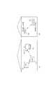
第2の実施例における無線LANの利用形態を示したのが図7である。 FIG. 7 shows the use form of the wireless LAN in the second embodiment.
自宅(704)では無線LANが利用されているものとする。701は802.11e規格準拠のQoS対応アクセスポイント(以下QAP2)、702は802.11e規格準拠のQoS対応無線LAN端末であるテレビ(以下QSTA2)、703はQAP1に映像ケーブルで接続されているHDD(Hard Disk Drive)レコーダーである。 It is assumed that a wireless LAN is used at home (704). 701 is a QoS-compliant access point (hereinafter referred to as QAP2) compliant with the 802.11e standard, 702 is a television (hereinafter referred to as QSTA2) which is a QoS-compliant wireless LAN terminal compliant with the 802.11e standard, and 703 is an HDD connected to the QAP1 via a video cable. It is a (Hard Disk Drive) recorder.
QSTA2(702)には無線LANユニットが内蔵されており、無線LANで受信した映像データを内蔵のMPEG2復号化ユニットで映像信号に変換してテレビ画面に表示する。 QSTA2 (702) has a built-in wireless LAN unit, which converts video data received by the wireless LAN into a video signal by a built-in MPEG2 decoding unit and displays it on a television screen.
QAP2(701)は、周辺の無線LAN端末のアクセス管理機能を備えている。さらに、QAP2(701)には無線映像データの符号化ユニットが内蔵されており、HDDプレーヤーからケーブルを介して受信した映像データを復号化して、無線LANによりQSTA2(702)に送信する。 QAP2 (701) has an access management function for peripheral wireless LAN terminals. Furthermore, the QAP2 (701) has a wireless video data encoding unit, which decodes the video data received from the HDD player via the cable and transmits it to the QSTA2 (702) by the wireless LAN.
QAP2(701)とQSTA2(702)は、どちらもIEEE802.11g及びIEEE802.11e規格に準拠した無線LAN機器であり、無線LANを介して相互に通信を行うことができる。 Both QAP2 (701) and QSTA2 (702) are wireless LAN devices compliant with the IEEE802.11g and IEEE802.11e standards, and can communicate with each other via the wireless LAN.
また、隣接する家(707)では非無線LAN機器であるNSTA3(705)とNSTA4(706)が利用されているものとする。 Further, it is assumed that NSTA3 (705) and NSTA4 (706), which are non-wireless LAN devices, are used in the adjacent house (707).
NSTA3(705)とNSTA3(706)は、無線LAN機器であるQAP2(701)およびQSTA2(702)で使用している無線周波数帯域と周波数帯域を使用しており、かつその送信電力はQAP2(701)にも十分に到達する強さとなっている。従って、NSTA3(705)とNSTA4(706)の間の無線通信は、QAP2(701)およびQSTA2(702)にとっては干渉電波となっている。 NSTA3 (705) and NSTA3 (706) use the radio frequency band and frequency band used by QAP2 (701) and QSTA2 (702), which are wireless LAN devices, and the transmission power is QAP2 (701). ) Is also strong enough to reach. Therefore, the wireless communication between NSTA3 (705) and NSTA4 (706) is an interference wave for QAP2 (701) and QSTA2 (702).
本実施例におけるQAP2(701)のブロック構成図を図9に示す。図2と比較すると、画像復号化部(205)の代わりに画像符号化部(905)を有している。他の構成は図2と同じであるので、同一記号を付することにより説明を省略する。 FIG. 9 shows a block diagram of QAP2 (701) in the present embodiment. Compared with FIG. 2, an image encoding unit (905) is provided instead of the image decoding unit (205). Since other configurations are the same as those in FIG. 2, the description is omitted by giving the same symbols.
画像符号部(905)では、HDDレコーダー(703)から入力された映像信号を、映像データに符号化し、メモリ(204)内の送信バッファ領域に一旦蓄積される。 In the image encoding unit (905), the video signal input from the HDD recorder (703) is encoded into video data and temporarily stored in a transmission buffer area in the memory (204).
そして、QSTA2(702)に映像データを送信する際は、メモリ(204)内の送信バッファ領域に蓄積した映像データを制御部(203)によって無線通信部(202)に転送する。無線通信部(202)では、転送されたデータにヘッダ情報を付加して無線LANのフレ−ムに構成し、RF部(201)を介してQSTA2(702)に送信する。 When transmitting video data to QSTA2 (702), the video data stored in the transmission buffer area in the memory (204) is transferred to the wireless communication unit (202) by the control unit (203). The wireless communication unit (202) adds header information to the transferred data to form a wireless LAN frame, and transmits the frame to the QSTA2 (702) via the RF unit (201).
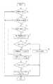
本実施例におけるQAP2(701)の動作フローを図8に示す。図5と比較すると、S8の動作が異なる(S8’とする)。その他の動作は図5と同じであるので同一記号を付すことにより説明を省略する。 The operation flow of QAP2 (701) in the present embodiment is shown in FIG. Compared to FIG. 5, the operation of S8 is different (referred to as S8 '). Since other operations are the same as those in FIG.
S8’において、QAP1(701)はQSTA2(702)に対して、受信データバッファのサイズを増大するよう要求する。要求を受けたQSTA2(702)は受信データバッファのサイズを増大するので、その後QAP2(702)に送信機会が与えられたときに、QAP1(701)からQSTA2(702)に対して、一度に多量のデータを送受信できるようになる。 In S8 ', QAP1 (701) requests QSTA2 (702) to increase the size of the received data buffer. The QSTA2 (702) that has received the request increases the size of the reception data buffer, so that when QAP2 (702) is subsequently given a transmission opportunity, the QSTA1 (701) increases a large amount from the QSTA2 (702) at a time. You can send and receive data.
本実施例によれば、QAPからQSTAに対し、ストリームデータの通信を行う場合においても、第1の実施例と同様の作用効果を得ることができる。 According to the present embodiment, even when stream data is communicated from QAP to QSTA, the same operational effects as those of the first embodiment can be obtained.
<第3の実施例>
上記実施例では、アクセスポイント(QAP)に本発明を適用した場合で説明したが、本発明を通信端末側(QSTA)に適用しても良い。<Third embodiment>
In the above embodiment, the present invention is applied to the access point (QAP). However, the present invention may be applied to the communication terminal side (QSTA).
さらに、上記実施例では干渉源となる無線機器として、非無線LAN機器の場合について説明したが、図10に示すような、いわゆる隠れ端末問題が発生したときの無線LAN機器同士による干渉が生じた場合も、本発明は適応可能である。 Furthermore, in the above-described embodiment, the case of a non-wireless LAN device has been described as a wireless device serving as an interference source. However, when a so-called hidden terminal problem occurs, interference between wireless LAN devices occurs as shown in FIG. Even in this case, the present invention is applicable.
図10において、1001と1004はアクセスポイントであるQAP4とQAP5、1002と104は無線LAN端末であるQSTA4とQSTA5である。QSTA4(1002)は、QAP4(1001)とHCCAにより無線通信を行っており、QSTA5(1005)はQAP5(1004)とHCCAにより無線通信を行っているものとする。 In FIG. 10, reference numerals 1001 and 1004 denote access points QAP4 and QAP5, and 1002 and 104 denote wireless LAN terminals QSTA4 and QSTA5. It is assumed that QSTA4 (1002) performs wireless communication with QAP4 (1001) and HCCA, and QSTA5 (1005) performs wireless communication with QAP5 (1004) and HCCA.
QAP4(1001)からの無線電波はQSTA4(1002)では受信でき、QAP5(1004)では受信できない範囲(1008)まで到達している。また、QAP5(1004)からの無線電波はQSTA4(1002)では受信でき、QAP4(1001)では受信できない範囲(1007)まで到達している。 The radio wave from QAP4 (1001) can be received by QSTA4 (1002) and has reached a range (1008) that cannot be received by QAP5 (1004). Further, the radio wave from QAP5 (1004) can be received by QSTA4 (1002) and has reached a range (1007) that cannot be received by QAP4 (1001).
従って、お互いに無線電波が到達しない位置に設置されたQAP4(1001)とQAP5(1004)の間では各々の電波が検出できないので、それぞれ非同期に無線電波を送信する。その結果、QAP4(1001)から送信される信号とQAP5(1004)から送信される信号の送信タイミングが重なり、干渉してしまう場合がある。 Accordingly, since each radio wave cannot be detected between QAP4 (1001) and QAP5 (1004) installed at positions where radio radio waves do not reach each other, radio radio waves are transmitted asynchronously. As a result, the transmission timing of the signal transmitted from QAP4 (1001) and the signal transmitted from QAP5 (1004) may overlap and interfere with each other.
そこでQSTA4(1001)は、QAP4(1001)により送信されるポーリング信号が、QAP5(1005)からのポーリング信号やダウンリンクデータ信号の干渉により正しく受信できない事を検出した場合は、上記実施例に示す干渉回避手段を実行する。 Therefore, when the QSTA4 (1001) detects that the polling signal transmitted by the QAP4 (1001) cannot be correctly received due to the interference of the polling signal from the QAP5 (1005) or the downlink data signal, it is shown in the above embodiment. Execute interference avoidance means.
本実施例によれば、隠れ端末問題等により無線LAN機器同士で干渉が生じた場合も、上記実施例と同様の作用効果を得ることができる。 According to the present embodiment, even when interference occurs between the wireless LAN devices due to a hidden terminal problem or the like, it is possible to obtain the same effects as the above-described embodiment.
また、上記のような隠れ端末の検出は送信タイミングによる検出に限定されるものではなく、予め帯域予約している送信タイミングで送信権を得られないことを検出するようにしても良い。 The detection of the hidden terminal as described above is not limited to the detection based on the transmission timing, and it may be detected that the transmission right cannot be obtained at the transmission timing reserved in advance.
<その他の実施例>
上記実施例では、無線LANのRF部を用いて干渉電波の検出を行っていたが、同じ周波数帯域の受信部を独立して設けることにより、干渉電波を検出するようにしてもよい。また、RF部と無線通信部をそれぞれ2系統設けて、1系統を周波数チャネルサーチ専用の受信部として構成してもよい。この場合は、送受信処理と平行してチャネルサーチ処理を行うので、処理を素早く実行することが可能になる。<Other examples>
In the above-described embodiment, the interference radio wave is detected using the RF unit of the wireless LAN. However, the interference radio wave may be detected by providing a reception unit of the same frequency band independently. Alternatively, two systems each of the RF unit and the wireless communication unit may be provided, and one system may be configured as a receiving unit dedicated to frequency channel search. In this case, since the channel search process is performed in parallel with the transmission / reception process, the process can be executed quickly.
また受信バッファおよび送信バッファは、ワークメモリと共通ではなく、通信用に独立したメモリとして設けても良い。 Further, the reception buffer and the transmission buffer are not common to the work memory, and may be provided as independent memories for communication.
また、上記実施例では、干渉電波を検出したときにHCCAを使用している場合は、常にEDCAに移行するようにしていたが、HCCAによるストリーム通信の周期性が維持できているかどうかを判定基準とし、維持できない場合にEDCAに移行するようにしてもよい。 In the above embodiment, when HCCA is used when an interference radio wave is detected, the EDCA is always shifted to EDCA. However, whether or not the periodicity of stream communication by HCCA can be maintained is determined. If it cannot be maintained, it may be shifted to EDCA.
また、EDCAにより一定時間通信を行った後、再度HCCAに移行してもよい。これにより、干渉電波がなくなった後は、HCCAにより周期的なストリームデータ通信を行うことができる。 Moreover, after performing communication for a certain time by EDCA, you may transfer to HCCA again. Thereby, after the interference radio wave disappears, periodic stream data communication can be performed by HCCA.
また、上記実施例ではQAPとケーブルでテレビやHDDプレーヤを接続している場合について説明したが、QAPにテレビ機能やHDDプレーヤ機能を内蔵してもよい。 In the above embodiment, the case where a TV or HDD player is connected with a QAP and a cable has been described. However, a TV function or an HDD player function may be incorporated in the QAP.
また、無線LANはIEEE802.11gに限らず、IEEE802.11b等でもよく、IEEE802.11aのようなその他の周波数帯域を用いる方式であっても良い。 The wireless LAN is not limited to IEEE802.11g, but may be IEEE802.11b or the like, or may be a system using other frequency bands such as IEEE802.11a.
また、上記実施例では無線LANについて説明したが、集中制御モードと分散制御モードに対応していれば、他の無線通信方式であっても本発明は適用可能である。 In the above embodiment, the wireless LAN has been described. However, the present invention can be applied to other wireless communication systems as long as the centralized control mode and the distributed control mode are supported.
また、上記実施例ではPCやテレビ、HDDプレーヤを用いる場合について説明したが、デジタルビデオカメラ等、他の機器においても本発明は適用可能である。 In the above embodiment, the case where a PC, a television, and an HDD player are used has been described. However, the present invention can be applied to other devices such as a digital video camera.
本発明の目的は、前述した実施例の機能を実現するソフトウエアのプログラムコードを記録した記録媒体を、システムあるいは装置に供給し、そのシステムあるいは装置のコンピュータ(またはCPUまたはMPU)が記録媒体に格納されたプログラムコードを読み出し実行することによっても、達成されることは言うまでもない。この場合、記憶媒体から読み出されたプログラムコード自体が前述した実施形態の機能を実現することとなり、そのプログラムコードを記憶した記憶媒体は本発明を構成することになる。 An object of the present invention is to supply a recording medium recording software program codes for realizing the functions of the above-described embodiments to a system or apparatus, and the computer (or CPU or MPU) of the system or apparatus stores the recording medium. Needless to say, this can also be achieved by reading and executing the stored program code. In this case, the program code itself read from the storage medium realizes the functions of the above-described embodiment, and the storage medium storing the program code constitutes the present invention.
プログラムコードを供給するための記憶媒体としては、例えば、フレキシブルディスク、ハードディスク、光ディスク、光磁気ディスク、CD−ROM、CD−R、磁気テープ、不揮発性のメモリカード、ROM、DVDなどを用いることができる。 As a storage medium for supplying the program code, for example, a flexible disk, a hard disk, an optical disk, a magneto-optical disk, a CD-ROM, a CD-R, a magnetic tape, a nonvolatile memory card, a ROM, a DVD, or the like is used. it can.
また、コンピュータが読み出したプログラムコードを実行することにより、前述した実施例の機能が実現されるだけでなく、そのプログラムコードの指示に基づき、コンピュータ上で稼動しているOperating System(OS)などが実際の処理の一部または全部を行い、その処理によって前述した実施例の機能が実現される場合も含まれることは言うまでもない。 Further, by executing the program code read by the computer, not only the functions of the above-described embodiments are realized, but also an operating system (OS) running on the computer based on the instruction of the program code. It goes without saying that a case where the function of the above-described embodiment is realized by performing part or all of the actual processing and the processing is included.
さらに、記憶媒体から読み出されたプログラムコードが、コンピュータに挿入された機能拡張ボードやコンピュータに接続された機能拡張ユニットに備わるメモリに書きこまれた後、そのプログラムコードの指示に基づき、その機能拡張ボードや機能拡張ユニットに備わるCPUなどが実際の処理の一部または全部を行い、その処理によって前述した実施形態の機能が実現される場合も含まれることは言うまでもない。 Furthermore, after the program code read from the storage medium is written to the memory provided in the function expansion board inserted into the computer or the function expansion unit connected to the computer, the function is based on the instruction of the program code. It goes without saying that the CPU of the expansion board or function expansion unit performs part or all of the actual processing, and the functions of the above-described embodiments are realized by the processing.
以上のように、本実施例によれば、干渉電波により集中制御方式による通信が妨害される時には、分散制御方式に変更して周波数帯域の空いているタイミングで適応的にデータ送信する。従って、予定されていたデータ受信のアンダーフローを防ぐことが可能になる。さらには、干渉電波による不定期な妨害によってデータの流量の変動が増大したら、無線通信装置の受信バッファ容量を大きくするので、通信中に無線通信装置内のデータがオーバーフローすることなく通信を継続することが可能になる。 As described above, according to the present embodiment, when communication by the centralized control method is interrupted by the interference radio wave, the data is adaptively transmitted at a timing when the frequency band is vacant by changing to the distributed control method. Therefore, it is possible to prevent a planned underflow of data reception. Furthermore, if the fluctuation in the data flow rate increases due to irregular interference caused by interference radio waves, the reception buffer capacity of the wireless communication device is increased, so that communication continues without overflowing data in the wireless communication device during communication. It becomes possible.
Claims (6)
Translated fromJapanese干渉電波を検出するための検出工程と、
前記検出工程における検出結果に応じて、前記集中制御方式と前記分散制御方式とを切替える切替工程と、
を有することを特徴とする通信方法。By selectively using a plurality of communication methods including a centralized control method for transmitting and receiving data based on control of the control device and a distributed control method in which each communication device transmits and receives data in an autonomous and distributed manner, A communication method for communicating with a communication device, comprising:
A detection process for detecting interfering radio waves;
A switching step of switching between the centralized control method and the distributed control method according to the detection result in the detection step,
A communication method characterized by comprising:
前記検出工程における検出結果に応じて、前記蓄積工程において一時的に蓄積可能なデータ量を変更して他の通信装置と通信することを特徴とする請求項1記載の通信方法。Having a storage process for temporarily storing received data;
The communication method according to claim 1, wherein communication is performed with another communication apparatus by changing a data amount that can be temporarily stored in the storage step according to a detection result in the detection step.
前記探索工程における探索結果と、前記検出工程における検出結果とに応じて、前記切替工程において前記集中制御方式と前記分散制御方式とを切替えることを特徴とする請求項1又は2記載の通信方法。According to the detection result in the detection step, the search step for searching for another frequency band different from the frequency band in use,
The communication method according to claim 1 or 2, wherein the central control method and the distributed control method are switched in the switching step according to a search result in the search step and a detection result in the detection step.
干渉電波を検出する検出手段と、
前記検出手段による検出結果に応じて、前記集中制御方式と前記分散制御方式とを切替える切替手段と、
を備えることを特徴とする通信装置。By selectively using a plurality of communication methods including a centralized control method for transmitting and receiving data based on control of the control device and a distributed control method in which each communication device transmits and receives data in an autonomous and distributed manner, In a communication device that communicates with a communication device,
Detection means for detecting interference radio waves;
Switching means for switching between the centralized control method and the distributed control method according to the detection result by the detecting means;
A communication apparatus comprising:
A program for causing a computer to execute the communication method according to claim 1.
Priority Applications (2)
| Application Number | Priority Date | Filing Date | Title |
|---|---|---|---|
| JP2006080907AJP4804184B2 (en) | 2006-03-23 | 2006-03-23 | COMMUNICATION METHOD, COMMUNICATION DEVICE, COMPUTER PROGRAM |
| US11/680,944US8488570B2 (en) | 2006-03-23 | 2007-03-01 | Communication method, communication apparatus, and computer program |
Applications Claiming Priority (1)
| Application Number | Priority Date | Filing Date | Title |
|---|---|---|---|
| JP2006080907AJP4804184B2 (en) | 2006-03-23 | 2006-03-23 | COMMUNICATION METHOD, COMMUNICATION DEVICE, COMPUTER PROGRAM |
Publications (2)
| Publication Number | Publication Date |
|---|---|
| JP2007259079Atrue JP2007259079A (en) | 2007-10-04 |
| JP4804184B2 JP4804184B2 (en) | 2011-11-02 |
Family
ID=38533332
Family Applications (1)
| Application Number | Title | Priority Date | Filing Date |
|---|---|---|---|
| JP2006080907AActiveJP4804184B2 (en) | 2006-03-23 | 2006-03-23 | COMMUNICATION METHOD, COMMUNICATION DEVICE, COMPUTER PROGRAM |
Country Status (2)
| Country | Link |
|---|---|
| US (1) | US8488570B2 (en) |
| JP (1) | JP4804184B2 (en) |
Cited By (2)
| Publication number | Priority date | Publication date | Assignee | Title |
|---|---|---|---|---|
| JP2007295278A (en)* | 2006-04-25 | 2007-11-08 | Nec Corp | Method of averting radio wave interference, wireless terminal, radio wave interference averting program, and radio communication system |
| US9232539B2 (en) | 2012-02-20 | 2016-01-05 | Mitsubishi Electric Corporation | Communication system, communication terminal, and communication method |
Families Citing this family (3)
| Publication number | Priority date | Publication date | Assignee | Title |
|---|---|---|---|---|
| US8312310B2 (en)* | 2007-05-01 | 2012-11-13 | Canon Kabushiki Kaisha | Apparatus and method for changing clock frequency and modulation method based on current state |
| WO2011096045A1 (en)* | 2010-02-02 | 2011-08-11 | 株式会社 東芝 | Communication device having storage function |
| GB2478323A (en)* | 2010-03-03 | 2011-09-07 | Adam Comm Systems Internat Ltd | Wireless communication in building management control. |
Citations (5)
| Publication number | Priority date | Publication date | Assignee | Title |
|---|---|---|---|---|
| JPH0548610A (en)* | 1991-08-14 | 1993-02-26 | Tokyo Electric Co Ltd | Radio communication system |
| JP2003198564A (en)* | 2001-12-27 | 2003-07-11 | Nec Corp | Radio base station device, radio communication system and communication control method |
| US20040264561A1 (en)* | 2002-05-02 | 2004-12-30 | Cohda Wireless Pty Ltd | Filter structure for iterative signal processing |
| US6990116B1 (en)* | 2001-01-12 | 2006-01-24 | 3Com Corporation | Method and system for improving throughput over wireless local area networks with mode switching |
| WO2006022477A1 (en)* | 2004-08-27 | 2006-03-02 | Samsung Electronics Co., Ltd. | Wireless networking apparatus and channel switching method using the same |
Family Cites Families (9)
| Publication number | Priority date | Publication date | Assignee | Title |
|---|---|---|---|---|
| JP2746183B2 (en) | 1995-04-04 | 1998-04-28 | 日本電気株式会社 | Multiple access method |
| JP3489472B2 (en) | 1999-03-02 | 2004-01-19 | 日本電信電話株式会社 | Radio packet control station |
| JP4654507B2 (en) | 2000-11-17 | 2011-03-23 | パナソニック株式会社 | access point |
| JP4021367B2 (en) | 2003-05-07 | 2007-12-12 | シャープ株式会社 | Base station, mobile station and radio communication system |
| US7146133B2 (en)* | 2003-06-19 | 2006-12-05 | Microsoft Corporation | Wireless transmission interference avoidance on a device capable of carrying out wireless network communications |
| WO2005011307A2 (en)* | 2003-07-24 | 2005-02-03 | Koninklijke Philips Electronics, N.V. | Admission control to wireless network based on guaranteed transmission rate |
| US8842657B2 (en)* | 2003-10-15 | 2014-09-23 | Qualcomm Incorporated | High speed media access control with legacy system interoperability |
| EP1526685A1 (en)* | 2003-10-24 | 2005-04-27 | International University Bremen Gmbh | Inter-Cell Interference mitigation technique using reservation indicators |
| US7395064B2 (en)* | 2004-07-14 | 2008-07-01 | Intel Corporation | Systems and methods of distributed self-configuration for wireless networks |
- 2006
- 2006-03-23JPJP2006080907Apatent/JP4804184B2/enactiveActive
- 2007
- 2007-03-01USUS11/680,944patent/US8488570B2/enactiveActive
Patent Citations (5)
| Publication number | Priority date | Publication date | Assignee | Title |
|---|---|---|---|---|
| JPH0548610A (en)* | 1991-08-14 | 1993-02-26 | Tokyo Electric Co Ltd | Radio communication system |
| US6990116B1 (en)* | 2001-01-12 | 2006-01-24 | 3Com Corporation | Method and system for improving throughput over wireless local area networks with mode switching |
| JP2003198564A (en)* | 2001-12-27 | 2003-07-11 | Nec Corp | Radio base station device, radio communication system and communication control method |
| US20040264561A1 (en)* | 2002-05-02 | 2004-12-30 | Cohda Wireless Pty Ltd | Filter structure for iterative signal processing |
| WO2006022477A1 (en)* | 2004-08-27 | 2006-03-02 | Samsung Electronics Co., Ltd. | Wireless networking apparatus and channel switching method using the same |
Cited By (2)
| Publication number | Priority date | Publication date | Assignee | Title |
|---|---|---|---|---|
| JP2007295278A (en)* | 2006-04-25 | 2007-11-08 | Nec Corp | Method of averting radio wave interference, wireless terminal, radio wave interference averting program, and radio communication system |
| US9232539B2 (en) | 2012-02-20 | 2016-01-05 | Mitsubishi Electric Corporation | Communication system, communication terminal, and communication method |
Also Published As
| Publication number | Publication date |
|---|---|
| JP4804184B2 (en) | 2011-11-02 |
| US20070223511A1 (en) | 2007-09-27 |
| US8488570B2 (en) | 2013-07-16 |
Similar Documents
| Publication | Publication Date | Title |
|---|---|---|
| JP4777614B2 (en) | System and method for performing fast channel switching in a wireless medium | |
| JP5159539B2 (en) | Communication device, communication device control method, and program. | |
| US20200008200A1 (en) | Non-contiguous channel allocation over multi-channel wireless networks | |
| US11778553B2 (en) | Communication apparatus, method for controlling the same, and non-transitory computer-readable storage medium | |
| US20070232303A1 (en) | Wireless communication apparatus and wireless communication method | |
| KR20100059804A (en) | System and method for a plurality of competitive access intervals | |
| US11659591B2 (en) | Wireless communication method and wireless communication terminal using multiple channels | |
| US8219029B2 (en) | Wireless communication device, program, method, and system for communicating operation instruction information | |
| JP4804184B2 (en) | COMMUNICATION METHOD, COMMUNICATION DEVICE, COMPUTER PROGRAM | |
| US20180220454A1 (en) | Channel access method, station and system | |
| US20250274984A1 (en) | Communication apparatus, control method of communication apparatus, and a non-transitory computer-readable storage medium | |
| JP7632577B2 (en) | Communication Equipment | |
| JP7387258B2 (en) | Communication devices, communication methods and programs | |
| JP7370697B2 (en) | Communication device, control method, and program | |
| JP7370696B2 (en) | Communication device, control method, and program | |
| KR100965889B1 (en) | System and method for wireless communication of uncompressed video with beacon design | |
| US20250039924A1 (en) | Wireless communication method and wireless communication terminal using multiple channels | |
| JP7509145B2 (en) | Wireless communication device and method | |
| US12132534B2 (en) | Opportunistic sounding for low latency applications | |
| KR101675180B1 (en) | Wireless communication device, wireless communication method, and wireless communication system | |
| JP5151737B2 (en) | Wireless communication system, wireless communication apparatus, wireless communication method, and program | |
| US20140185547A1 (en) | Wireless communication apparatus and method | |
| KR101561115B1 (en) | Method for scanning access point in wireless local area network system | |
| JP2010021894A (en) | Communication apparatus and its control method |
Legal Events
| Date | Code | Title | Description |
|---|---|---|---|
| A621 | Written request for application examination | Free format text:JAPANESE INTERMEDIATE CODE: A621 Effective date:20090210 | |
| RD04 | Notification of resignation of power of attorney | Free format text:JAPANESE INTERMEDIATE CODE: A7424 Effective date:20100201 | |
| RD01 | Notification of change of attorney | Free format text:JAPANESE INTERMEDIATE CODE: A7421 Effective date:20100630 | |
| A977 | Report on retrieval | Free format text:JAPANESE INTERMEDIATE CODE: A971007 Effective date:20110104 | |
| A131 | Notification of reasons for refusal | Free format text:JAPANESE INTERMEDIATE CODE: A131 Effective date:20110111 | |
| A521 | Request for written amendment filed | Free format text:JAPANESE INTERMEDIATE CODE: A523 Effective date:20110314 | |
| TRDD | Decision of grant or rejection written | ||
| A01 | Written decision to grant a patent or to grant a registration (utility model) | Free format text:JAPANESE INTERMEDIATE CODE: A01 Effective date:20110802 | |
| A01 | Written decision to grant a patent or to grant a registration (utility model) | Free format text:JAPANESE INTERMEDIATE CODE: A01 | |
| A61 | First payment of annual fees (during grant procedure) | Free format text:JAPANESE INTERMEDIATE CODE: A61 Effective date:20110809 | |
| R151 | Written notification of patent or utility model registration | Ref document number:4804184 Country of ref document:JP Free format text:JAPANESE INTERMEDIATE CODE: R151 | |
| FPAY | Renewal fee payment (event date is renewal date of database) | Free format text:PAYMENT UNTIL: 20140819 Year of fee payment:3 |