JP2007258774A - Telephone set - Google Patents
Telephone setDownload PDFInfo
- Publication number
- JP2007258774A JP2007258774AJP2006076648AJP2006076648AJP2007258774AJP 2007258774 AJP2007258774 AJP 2007258774AJP 2006076648 AJP2006076648 AJP 2006076648AJP 2006076648 AJP2006076648 AJP 2006076648AJP 2007258774 AJP2007258774 AJP 2007258774A
- Authority
- JP
- Japan
- Prior art keywords
- base
- main body
- pedestal
- latch
- telephone
- Prior art date
- Legal status (The legal status is an assumption and is not a legal conclusion. Google has not performed a legal analysis and makes no representation as to the accuracy of the status listed.)
- Granted
Links
- NJPPVKZQTLUDBO-UHFFFAOYSA-NnovaluronChemical compoundC1=C(Cl)C(OC(F)(F)C(OC(F)(F)F)F)=CC=C1NC(=O)NC(=O)C1=C(F)C=CC=C1FNJPPVKZQTLUDBO-UHFFFAOYSA-N0.000claimsabstractdescription19
- 239000002184metalSubstances0.000claimsdescription7
- 238000009434installationMethods0.000abstract2
- 229920003002synthetic resinPolymers0.000description3
- 239000000057synthetic resinSubstances0.000description3
- 238000005452bendingMethods0.000description1
- 230000001771impaired effectEffects0.000description1
- 239000004973liquid crystal related substanceSubstances0.000description1
- 230000007774longtermEffects0.000description1
- 238000004519manufacturing processMethods0.000description1
- 238000012856packingMethods0.000description1
Images


Landscapes
- Casings For Electric Apparatus (AREA)
- Telephone Set Structure (AREA)
Abstract
Description
Translated fromJapanese本発明は卓上載置状態でも壁掛け状態でも使用可能な電話機に関する。 The present invention relates to a telephone that can be used both on a desktop and in a wall-mounted state.
卓上載置状態でも壁掛け状態でも使用可能な電話機については種々の提案がなされている。特許文献1、2にその例を見ることができる。また卓上型電話機の本体部の角度を調節可能にし、操作しやすい角度で使用できるようにするという提案も数多くなされている。特許文献3、4にその例を見ることができる。
従来の壁掛け型電話機では、操作性を向上させるため本体部の角度を調節可能にするといったことは考慮されていなかった。本発明はこの点に鑑みなされたもので、卓上載置状態でも壁掛け状態でも使用可能な電話機において、どちらの状態でも本体部の角度を調節することができ、それをコンパクトな角度調節装置で実現できるものを提供することを目的とする。 In conventional wall-mounted telephones, it has not been considered that the angle of the main body can be adjusted in order to improve operability. The present invention has been made in view of this point, and in a phone that can be used either on a table or in a wall, the angle of the main body can be adjusted in either state, and this is realized by a compact angle adjustment device. The purpose is to provide what can be done.
(1)上記目的を達成するために本発明の電話機は、卓上載置状態またはその底面を壁面に対面させた壁掛け状態での使用が可能な基台、ハンドセットを保持するクレイドル部と操作部とを有し、前記基台に垂直面内で傾動可能に連結された本体部、及び前記基台と本体部との相対角度を調節する角度調節装置を備え、前記本体部の筐体内にはこの筐体を支える垂直な支持板が設けられ、この支持板には前記基台に向かって凸をなす円弧溝が形成されるとともに、前記基台には前記筐体に形成されたスリットを通じて前記本体部に入り込む台座が設けられ、この台座には、前記支持板の円弧溝に係合して本体部を傾動可能に支える、互いに間隔を置いて配置された複数の支持軸と、前記円弧溝に沿って点在する複数の係合部のいずれかに係合して前記支持板と台座との相対移動を止めるラッチとが設けられていることを特徴としている。 (1) In order to achieve the above object, the telephone of the present invention includes a base that can be used in a table-mounted state or a wall-mounted state in which the bottom surface faces a wall surface, a cradle unit that holds a handset, and an operation unit. And a main body connected to the base so as to be tiltable in a vertical plane, and an angle adjusting device for adjusting a relative angle between the base and the main body. A vertical support plate for supporting the housing is provided, and the support plate is formed with a circular groove that protrudes toward the base, and the main body through the slit formed in the housing. A pedestal that enters the portion is provided, and the pedestal includes a plurality of support shafts that are spaced apart from each other and engage the arc groove of the support plate to support the main body portion in a tiltable manner, and the arc groove Engage with any of multiple engaging parts scattered along A latch stop relative movement between the support plate and the pedestal is characterized in that provided Te.
この構成によると、基台を壁掛け状態にすれば本体部も壁掛け状態になり、しかもその状態で本体部の角度を調節して使いやすい角度にすることができる。そして角度調節装置が本体部を傾けるやり方は、本体部の筐体を支える支持板の一箇所に円の中心軸を設け、この中心軸まわりに支持板を回動させるのではなく、支持板に形成した円弧溝に複数の支持軸を通し、この支持軸を基台側の台座で支持して支持板を円運動可能に支持する方式であるから、支持板が円の中心を含む扇形である必要がない。従って支持板は、円の周縁近くを弦で切り取ったような、比較的幅の狭い形状のもので十分であり、角度調節装置をコンパクトな構造とすることができる。また台座は本体部の筐体に形成されたスリットを通じて本体部内に入り込むものであるから、筐体に大きな開口を設けずに済み、本体部の美観を保つことができる。 According to this configuration, when the base is placed on the wall, the main body is also hung on the wall, and in this state, the angle of the main body can be adjusted to make it easy to use. The angle adjustment device tilts the main body part by providing a central axis of the circle at one place on the support plate that supports the housing of the main body part, and rotating the support plate around this central axis. A plurality of support shafts are passed through the formed arc groove, and this support shaft is supported by a base on the base side so that the support plate can be moved circularly. Therefore, the support plate has a sector shape including the center of the circle. There is no need. Therefore, it is sufficient for the support plate to have a relatively narrow shape such as a string cut off near the periphery of the circle, and the angle adjusting device can have a compact structure. In addition, since the pedestal enters the main body through a slit formed in the housing of the main body, it is not necessary to provide a large opening in the housing, and the aesthetic appearance of the main body can be maintained.
(2)また本発明は、上記構成の電話機において、前記支持板は複数のものが互いに間隔を置いて平行に配置され、それぞれの支持板に前記円弧溝が形成されており、前記支持軸は前記円弧溝の全てを串刺しにする形で配置されており、前記台座は、前記支持軸を、少なくともその両端近傍で支持することを特徴としている。 (2) Further, in the present invention, in the telephone having the above-described configuration, a plurality of the support plates are arranged in parallel with a space between each other, the arc grooves are formed in each of the support plates, and the support shaft is All the arc grooves are arranged in a skewered manner, and the pedestal supports the support shaft at least near both ends thereof.
この構成によると、互いに間隔を置いて平行に配置された複数の支持板を支持軸が串刺しにし、その支持軸の両端近傍を台座が支持するものであるから、強度の高い角度調節装置を得ることができる。
(3)また本発明は、上記構成の電話機において、前記円弧溝の内側面に形成された切り欠きが前記係合部を構成し、前記切り欠きに係合する軸が前記ラッチを構成することを特徴としている。According to this configuration, since the support shaft is skewered with a plurality of support plates arranged parallel to each other at intervals, the pedestal supports the vicinity of both ends of the support shaft, so that an angle adjusting device with high strength is obtained. be able to.
(3) According to the present invention, in the telephone configured as described above, a notch formed on an inner surface of the arc groove constitutes the engaging portion, and a shaft engaged with the notch constitutes the latch. It is characterized by.
この構成によると、係合部もラッチも構造が単純で製作容易である。
(4)また本発明は、上記構成の電話機において、前記ラッチは前記係合部に係合する方向に常時ばねで付勢されており、前記基台に設けられた操作レバーが前記ラッチに連結され、この操作レバーの操作で前記ラッチは前記係合部から外れることを特徴としている。According to this configuration, both the engaging portion and the latch have a simple structure and are easy to manufacture.
(4) Further, in the telephone having the above-described configuration, the latch is always urged by a spring in a direction in which the latch is engaged with the engaging portion, and an operation lever provided on the base is connected to the latch. The latch is disengaged from the engaging portion by the operation of the operation lever.
この構成によると、ラッチを係合部から外す操作を容易に行うことができる。
(5)また本発明は、上記構成の電話機において、前記支持板及び台座は金属製部品であることを特徴としている。According to this configuration, the operation of removing the latch from the engaging portion can be easily performed.
(5) The present invention is characterized in that, in the telephone having the above-described configuration, the support plate and the pedestal are metal parts.
この構成によると、角度調節装置を長年の使用にも耐え得る堅牢なものとすることができる。 According to this configuration, the angle adjusting device can be made robust enough to withstand long-term use.
本発明によると、卓上載置状態で本体部の角度が調節可能であることはもちろん、壁掛け状態でも本体部の角度を調節可能な電話機を提供することができる。そして角度調節装置は、円弧溝を有する支持板と、その円弧溝に係合する複数の支持軸とを用いて、コンパクトな構造とすることができる。また台座は本体部の筐体に形成されたスリットを通じて本体部内に入り込むものであるから、本体部の美観が大きく損なわれることがない。 ADVANTAGE OF THE INVENTION According to this invention, the telephone which can adjust the angle of a main-body part also in a wall-mounted state can be provided as well as the angle of a main-body part being adjustable in a desktop mounting state. The angle adjusting device can have a compact structure using a support plate having an arc groove and a plurality of support shafts engaged with the arc groove. Further, since the pedestal enters the main body through a slit formed in the housing of the main body, the aesthetic appearance of the main body is not greatly impaired.
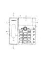
以下、本発明の一実施形態を図に基づき説明する。図1は正面側から見た電話機の斜視図、図2は図1からハンドセットを取り除いた状態の斜視図、図3は背面側から見た電話機の斜視図、図4は卓上載置状態の電話機の側面図、図5は卓上載置状態の電話機の側面図にして、図4と異なる角度状態のもの、図6は壁掛け状態の電話機の側面図、図7は壁掛け状態の電話機の側面図にして、図6と異なる角度状態のもの、図8は本体部及びハンドセットの正面図、図9は図8のA−A部断面図、図10は角度調節装置の斜視図、図11は角度調節装置の断面図、図12は図11と断面箇所を変えた角度調節装置の断面図である。 Hereinafter, an embodiment of the present invention will be described with reference to the drawings. 1 is a perspective view of the telephone as viewed from the front side, FIG. 2 is a perspective view of the telephone with the handset removed from FIG. 1, FIG. 3 is a perspective view of the telephone as viewed from the rear side, and FIG. FIG. 5 is a side view of a telephone set in a desktop state, and is an angle state different from FIG. 4, FIG. 6 is a side view of the telephone set in a wall hanging state, and FIG. 7 is a side view of the telephone set in a wall hanging state. FIG. 8 is a front view of the main body and the handset, FIG. 9 is a sectional view taken along the line AA of FIG. 8, FIG. 10 is a perspective view of the angle adjusting device, and FIG. FIG. 12 is a cross-sectional view of the angle adjusting device in which the cross-sectional portion is changed from FIG.
電話機1は基台10と本体部20を備える。基台10は平面形状円形で、その上に本体部20は、垂直面内で傾動可能に支持されている。基台10と本体部20を連結するのは後述する角度調節装置である。基台10は図1のように卓上載置状態で使用することも可能であり、また底面の壁掛け穴(図示せず)を利用して、図6のように底面を壁面に対面させた壁掛け状態で使用することも可能である。 The telephone 1 includes a
本体部20の筐体21の正面は、全体の中で右側3分の2ほどが操作部22として構成され、左側3分の1ほどがクレイドル部23として構成される。操作部22には、テンキー、ジョグキー、各種ファンクションキーなどのキー群24と、液晶パネルによる表示部25が配置される。クレイドル部23には、通話回線を開閉するスイッチレバー26と、ハンドセット40を保持する隆起部27とが設けられている。ハンドセット40は図示しないカールコードで本体部20に接続される。 The front side of the
隆起部27によるハンドセット40の保持につき説明する。隆起部27は、正面から見ると上下方向に長い長円形をなしており、上端には長円形の長軸方向に突き出す突起28が形成されている。ハンドセット40の送話部41と受話部42(図9参照)の間には、隆起部27を受け入れる長円形の穴43が形成される。穴43の上端には突起28を受け入れる凹部44が形成されている。穴43に隆起部27を嵌合させ、凹部44に突起28を係合させることにより、ハンドセット40はがたつきの少ない状態でクレイドル部23に保持される。保持されたハンドセット40は、それを斜め上にずらすことによってしか隆起部27から外れない。従ってこの保持構造は地震などの振動にも強い。角度調節装置により本体部20の角度がどのように調節されたとしても、隆起部27と突起28の組み合わせでハンドセット40を保持することができる。 The holding of the
穴43は透明な合成樹脂製のパネル45(図9参照)で塞がれ、素通しではない。パネル45はハンドセット40の背面側(送話口や受話口のない側)の表面の一部を構成する。 隆起部27もその頂部は透明な合成樹脂製のパネル29(図9参照)で構成される。パネル29はLED30で照明される。LED30は本体部20の中に配置された電子回路基板31の表面に実装されている。LED30にはリフレクタ32が組み合わされ、LED30の放つ光がパネル29に集中するようになっている。 The
クレイドル部23には、隆起部27より上の箇所にスイッチレバー26が設けられている。スイッチレバー26の先端はクレイドル部23に形成された貫通孔33から突き出す。ハンドセット40を隆起部27に掛けると受話部42でスイッチレバー26が押し込まれ、
電話機1は回線開放状態となる。ハンドセット40を隆起部27から外すとスイッチレバー26が突出し、電話機1は回線閉成状態となる。The
The telephone 1 is in a line open state. When the
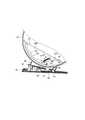
続いて、基台10と本体部20を連結する角度調節装置50の構造を図10−12に基づき説明する。角度調節装置50には基台10に固定される部分と本体部20に固定される部分とがある。基台10に固定される部分の中心となるのが金属製の台座51である。台座51は板金を断面コ字形に折曲したものであり、基台10にねじ止めされる中央部分51Cの両側に、互いに間隔を置いて平行に配置される1対の垂直部分51Vを設けた形になっている。垂直部分51Vは筐体21に形成したスリット34(図3参照)を通じて本体部20の内部に入り込む。 Then, the structure of the
本体部20に入り込んだ1対の垂直部分51Vは、本体部20の内面に固定された金属製の傾動台52を挟む形になる。台座51と同様、傾動台52も板金を断面コ字形に折曲したものであり、筐体21にねじ止めされる中央部分52Cの両側に、互いに間隔を置いて平行に配置される1対の垂直な支持板52Vを設けた形になっている。なお筐体21の側面形状に合わせ、支持板52Vは円の周縁近くを弦で切り取った三日月形状に成形されている。 The pair of
1対の支持板52Vには、それぞれ基台10に向かって凸をなす円弧溝53が形成される。1対の垂直部分51Vは、1対の円弧溝53を串刺しにする支持軸54、55を、各々軸の両端部で支持する。支持軸54、55は水平であり、且つ互いに間隔を置いて平行に配置されている。円弧溝53を支持軸54、55に対して滑らせると、傾動台52には円弧の中心まわりに回転しているのと同様の円運動が生じる。この円運動は、垂直面内における本体部20の傾き(tilt)となって表れる。 The pair of
円弧溝53の一方の端に支持軸54が当たる角度と、円弧溝53の他方の端に支持軸55が当たる角度との間で、傾動台52と台座51とは相対移動可能である。その中間の数箇所の位置で相対移動を止める仕組みを角度調節装置50は備える。その仕組みは次の通りである。 The tilting
まず、円弧溝53に沿って複数の係合部56を点在させる。係合部56は円弧溝53の上方の内側面に形成された切り欠きからなる。そして台座51に設けられたラッチ57をいずれかの係合部56に係合させて支持板52Vと台座51との相対移動を止める。 First, a plurality of engaging
ラッチ57は、切り欠きに係合する軸58と、軸58の両端を支持軸54の両端に連結するリンク59により構成される。ラッチ57は、リンク59と垂直部分51Vとを連結する引張コイルばね60により、図11において常時時計回り方向に、すなわち軸58が係合部56に係合する方向に付勢されている。 The
ラッチ57を係合部56から外すのは操作レバー61である。操作レバー61は、本体部20の筐体21の外側で、軸62により垂直部分51Vに取り付けられている。軸58は傾動台52の外側にアーム63を支持しており、両側のアーム63をブリッジ部64が連結している。そしてブリッジ部64の上を操作レバー61が通る。操作レバー61を自由にしておくと筐体21に当たって音を立てるので、基台10には操作レバー61が筐体21に当たらないようにするストッパ65が設けられている。 It is the operating
基台10にはゴムや軟質合成樹脂のブロックからなる弾性部材66が金具67によって固定されている。弾性部材66は筐体21の外面に当たって本体部20に上向きの力を加え、円弧溝53の下方の内側面を支持軸54、55に当接させてがたつきを防止する働きをする。 An
図4は、電話機1を梱包箱から取り出し、そのまま卓上に置いた状態を示す。操作レバー61の端を指で押し下げると、操作レバー61からブリッジ部64、ブリッジ部64からアーム63を経てラッチ57に力が加わり、ラッチ57は現在の係合部56から抜け出す。この状態で本体部20の傾きを変え、所望の角度に近くなったところで操作レバー61から指を離す。そのまま本体部20の傾きを少し変えてやれば、ラッチ57は引張コイルばね60の力で最寄りの係合部56に係合する。これにより、本体部20はほぼ所望の角度に落ち着く。図5には本体部20の角度を図4よりも水平に近く調節した状態が描かれている。 FIG. 4 shows a state in which the telephone 1 is taken out from the packing box and placed on the table as it is. When the end of the
電話機1を壁掛け状態で使用するときにも操作レバー61で本体部20の角度を変えることができる。図6ではハンドセット40がほぼ垂直をなしているが、図7の状態ではハンドセット40が斜めになっている。ハンドセット40の取りやすさや表示部25の見やすさを考慮して、適当な角度に固定すればよい。 Even when the telephone 1 is used in a wall-mounted state, the
本発明は卓上据え置きと壁掛けに兼用できるタイプの電話機に広く利用可能である。 The present invention can be widely used for telephones of a type that can be used for both desktop and wall mounting.
1 電話機
10 基台
20 本体部
22 操作部
23 クレイドル部
27 隆起部
40 ハンドセット
43 穴
50 角度調節装置
51 台座
52 傾動台
52V 支持板
53 円弧溝
54、55 支持軸
56 係合部
57 ラッチ
60 引張コイルばね
61 操作レバーDESCRIPTION OF SYMBOLS 1
Claims (5)
Translated fromJapanese前記本体部の筐体内にはこの筐体を支える垂直な支持板が設けられ、この支持板には前記基台に向かって凸をなす円弧溝が形成されるとともに、
前記基台には前記筐体に形成されたスリットを通じて前記本体部に入り込む台座が設けられ、この台座には、前記支持板の円弧溝に係合して本体部を傾動可能に支える、互いに間隔を置いて配置された複数の支持軸と、前記円弧溝に沿って点在する複数の係合部のいずれかに係合して前記支持板と台座との相対移動を止めるラッチとが設けられていることを特徴とする電話機。It has a base that can be used in a table-mounted state or a wall-mounted state with its bottom face facing the wall, a cradle that holds the handset, and an operating part, and is connected to the base so that it can tilt in a vertical plane. And an angle adjusting device for adjusting a relative angle between the base and the main body,
A vertical support plate for supporting the housing is provided in the housing of the main body, and an arc groove that protrudes toward the base is formed on the support plate.
The base is provided with a pedestal that enters the main body through a slit formed in the housing, and the pedestal engages with the arc groove of the support plate to support the main body so as to be tilted. And a plurality of support shafts, and a latch that engages with any of the plurality of engaging portions scattered along the arc groove to stop the relative movement between the support plate and the pedestal. A telephone characterized by the fact that
前記支持軸は前記円弧溝の全てを串刺しにする形で配置されており、
前記台座は、前記支持軸を、少なくともその両端近傍で支持することを特徴とする請求項1に記載の電話機。A plurality of the support plates are arranged parallel to each other at intervals, and the arc groove is formed on each support plate,
The support shaft is arranged in a form that skewers all the arc grooves,
The telephone according to claim 1, wherein the pedestal supports the support shaft at least in the vicinity of both ends thereof.
Priority Applications (1)
| Application Number | Priority Date | Filing Date | Title |
|---|---|---|---|
| JP2006076648AJP4522382B2 (en) | 2006-03-20 | 2006-03-20 | Telephone |
Applications Claiming Priority (1)
| Application Number | Priority Date | Filing Date | Title |
|---|---|---|---|
| JP2006076648AJP4522382B2 (en) | 2006-03-20 | 2006-03-20 | Telephone |
Publications (2)
| Publication Number | Publication Date |
|---|---|
| JP2007258774Atrue JP2007258774A (en) | 2007-10-04 |
| JP4522382B2 JP4522382B2 (en) | 2010-08-11 |
Family
ID=38632624
Family Applications (1)
| Application Number | Title | Priority Date | Filing Date |
|---|---|---|---|
| JP2006076648AExpired - Fee RelatedJP4522382B2 (en) | 2006-03-20 | 2006-03-20 | Telephone |
Country Status (1)
| Country | Link |
|---|---|
| JP (1) | JP4522382B2 (en) |
Cited By (9)
| Publication number | Priority date | Publication date | Assignee | Title |
|---|---|---|---|---|
| JP2013532397A (en)* | 2010-04-27 | 2013-08-15 | ヒューレット−パッカード デベロップメント カンパニー エル.ピー. | Chassis, base, extension and curved track |
| KR20150136093A (en)* | 2013-03-28 | 2015-12-04 | 마이크로소프트 테크놀로지 라이센싱, 엘엘씨 | Hinge mechanism for rotatable component attachment |
| US9964998B2 (en) | 2014-09-30 | 2018-05-08 | Microsoft Technology Licensing, Llc | Hinge mechanism with multiple preset positions |
| US10013030B2 (en) | 2012-03-02 | 2018-07-03 | Microsoft Technology Licensing, Llc | Multiple position input device cover |
| US10037057B2 (en) | 2016-09-22 | 2018-07-31 | Microsoft Technology Licensing, Llc | Friction hinge |
| US10344797B2 (en) | 2016-04-05 | 2019-07-09 | Microsoft Technology Licensing, Llc | Hinge with multiple preset positions |
| US10606322B2 (en) | 2015-06-30 | 2020-03-31 | Microsoft Technology Licensing, Llc | Multistage friction hinge |
| US10678743B2 (en) | 2012-05-14 | 2020-06-09 | Microsoft Technology Licensing, Llc | System and method for accessory device architecture that passes via intermediate processor a descriptor when processing in a low power state |
| US10963087B2 (en) | 2012-03-02 | 2021-03-30 | Microsoft Technology Licensing, Llc | Pressure sensitive keys |
Citations (5)
| Publication number | Priority date | Publication date | Assignee | Title |
|---|---|---|---|---|
| JPS61107253U (en)* | 1984-12-17 | 1986-07-08 | ||
| JPH10222078A (en)* | 1997-02-07 | 1998-08-21 | Tec Corp | Display device with touch panel |
| JP2000200048A (en)* | 2000-01-14 | 2000-07-18 | Nippon Avionics Co Ltd | Terminal device tilt mechanism |
| JP2002106542A (en)* | 2000-09-28 | 2002-04-10 | Nec Mitsubishi Denki Visual Systems Kk | Hinge structure and display monitor |
| JP2004194090A (en)* | 2002-12-12 | 2004-07-08 | Iwatsu Electric Co Ltd | Auxiliary table with variable tilt angle of telephone operation surface |
- 2006
- 2006-03-20JPJP2006076648Apatent/JP4522382B2/ennot_activeExpired - Fee Related
Patent Citations (5)
| Publication number | Priority date | Publication date | Assignee | Title |
|---|---|---|---|---|
| JPS61107253U (en)* | 1984-12-17 | 1986-07-08 | ||
| JPH10222078A (en)* | 1997-02-07 | 1998-08-21 | Tec Corp | Display device with touch panel |
| JP2000200048A (en)* | 2000-01-14 | 2000-07-18 | Nippon Avionics Co Ltd | Terminal device tilt mechanism |
| JP2002106542A (en)* | 2000-09-28 | 2002-04-10 | Nec Mitsubishi Denki Visual Systems Kk | Hinge structure and display monitor |
| JP2004194090A (en)* | 2002-12-12 | 2004-07-08 | Iwatsu Electric Co Ltd | Auxiliary table with variable tilt angle of telephone operation surface |
Cited By (11)
| Publication number | Priority date | Publication date | Assignee | Title |
|---|---|---|---|---|
| JP2013532397A (en)* | 2010-04-27 | 2013-08-15 | ヒューレット−パッカード デベロップメント カンパニー エル.ピー. | Chassis, base, extension and curved track |
| US10013030B2 (en) | 2012-03-02 | 2018-07-03 | Microsoft Technology Licensing, Llc | Multiple position input device cover |
| US10963087B2 (en) | 2012-03-02 | 2021-03-30 | Microsoft Technology Licensing, Llc | Pressure sensitive keys |
| US10678743B2 (en) | 2012-05-14 | 2020-06-09 | Microsoft Technology Licensing, Llc | System and method for accessory device architecture that passes via intermediate processor a descriptor when processing in a low power state |
| KR20150136093A (en)* | 2013-03-28 | 2015-12-04 | 마이크로소프트 테크놀로지 라이센싱, 엘엘씨 | Hinge mechanism for rotatable component attachment |
| JP2016516952A (en)* | 2013-03-28 | 2016-06-09 | マイクロソフト テクノロジー ライセンシング,エルエルシー | Hinge mechanism for mounting rotatable parts |
| KR102168145B1 (en) | 2013-03-28 | 2020-10-20 | 마이크로소프트 테크놀로지 라이센싱, 엘엘씨 | Hinge mechanism for rotatable component attachment |
| US9964998B2 (en) | 2014-09-30 | 2018-05-08 | Microsoft Technology Licensing, Llc | Hinge mechanism with multiple preset positions |
| US10606322B2 (en) | 2015-06-30 | 2020-03-31 | Microsoft Technology Licensing, Llc | Multistage friction hinge |
| US10344797B2 (en) | 2016-04-05 | 2019-07-09 | Microsoft Technology Licensing, Llc | Hinge with multiple preset positions |
| US10037057B2 (en) | 2016-09-22 | 2018-07-31 | Microsoft Technology Licensing, Llc | Friction hinge |
Also Published As
| Publication number | Publication date |
|---|---|
| JP4522382B2 (en) | 2010-08-11 |
Similar Documents
| Publication | Publication Date | Title |
|---|---|---|
| JP4522382B2 (en) | Telephone | |
| CN100409705C (en) | Multifunctional mobile communication device with sliding display screen | |
| US6587333B2 (en) | Flat panel display apparatus and tilt/swivel mechanism therein | |
| KR101232951B1 (en) | Mobile phone with convenient visual/acoustic feeling and sliding-cradling apparatus thereof | |
| US8259443B2 (en) | Tilting portable electronic device | |
| KR101394667B1 (en) | Stand for desktop telephone | |
| EP1710987A1 (en) | Swing hinge device for mobile terminal | |
| JP4930426B2 (en) | Terminal device | |
| JP2008079194A (en) | Terminal device | |
| CN101465895A (en) | Angle-variable mechanism and table-top unit | |
| JP6561527B2 (en) | Support structure for electronic equipment | |
| JP2011175127A (en) | Electronic instrument | |
| JP4734284B2 (en) | Variable angle mechanism and electronic equipment | |
| EP1926115A2 (en) | Two-way key of portable terminal | |
| JP4781138B2 (en) | Telephone | |
| JP4915223B2 (en) | Connecting device | |
| JP4761344B2 (en) | Portable information terminal device | |
| EP1278354B1 (en) | Telephone with cantilever beam type cradle and handset cradled thereon | |
| JP6016592B2 (en) | Case for portable information terminal | |
| JP4843575B2 (en) | Tilt structure and electronic equipment | |
| JP2014022097A (en) | Switch mechanism and electronic device | |
| JP4917517B2 (en) | Slide rotation mounting unit and mobile phone | |
| JP2001167672A (en) | Composite key device | |
| JP2001273093A (en) | Operation part mechanism | |
| JP2009284017A (en) | Electronic apparatus equipped with display unit |
Legal Events
| Date | Code | Title | Description |
|---|---|---|---|
| A621 | Written request for application examination | Effective date:20081002 Free format text:JAPANESE INTERMEDIATE CODE: A621 | |
| A977 | Report on retrieval | Free format text:JAPANESE INTERMEDIATE CODE: A971007 Effective date:20100423 | |
| TRDD | Decision of grant or rejection written | ||
| A01 | Written decision to grant a patent or to grant a registration (utility model) | Free format text:JAPANESE INTERMEDIATE CODE: A01 Effective date:20100427 | |
| A01 | Written decision to grant a patent or to grant a registration (utility model) | Free format text:JAPANESE INTERMEDIATE CODE: A01 | |
| A61 | First payment of annual fees (during grant procedure) | Free format text:JAPANESE INTERMEDIATE CODE: A61 Effective date:20100525 | |
| FPAY | Renewal fee payment (prs date is renewal date of database) | Free format text:PAYMENT UNTIL: 20130604 Year of fee payment:3 | |
| FPAY | Renewal fee payment (prs date is renewal date of database) | Free format text:PAYMENT UNTIL: 20130604 Year of fee payment:3 | |
| S111 | Request for change of ownership or part of ownership | Free format text:JAPANESE INTERMEDIATE CODE: R313115 | |
| FPAY | Renewal fee payment (prs date is renewal date of database) | Free format text:PAYMENT UNTIL: 20130604 Year of fee payment:3 | |
| R350 | Written notification of registration of transfer | Free format text:JAPANESE INTERMEDIATE CODE: R350 | |
| LAPS | Cancellation because of no payment of annual fees |