JP2007253809A - Driving posture adjusting device, automobile and driving posture adjusting method - Google Patents
Driving posture adjusting device, automobile and driving posture adjusting methodDownload PDFInfo
- Publication number
- JP2007253809A JP2007253809AJP2006081198AJP2006081198AJP2007253809AJP 2007253809 AJP2007253809 AJP 2007253809AJP 2006081198 AJP2006081198 AJP 2006081198AJP 2006081198 AJP2006081198 AJP 2006081198AJP 2007253809 AJP2007253809 AJP 2007253809A
- Authority
- JP
- Japan
- Prior art keywords
- driver
- pedal
- seat
- physique
- distance
- Prior art date
- Legal status (The legal status is an assumption and is not a legal conclusion. Google has not performed a legal analysis and makes no representation as to the accuracy of the status listed.)
- Pending
Links
Images


Landscapes
- Steering Controls (AREA)
- Auxiliary Drives, Propulsion Controls, And Safety Devices (AREA)
- Braking Elements And Transmission Devices (AREA)
Abstract
Description
Translated fromJapanese本発明は、運転者の運転姿勢を調節する運転姿勢調節装置、自動車及び運転姿勢調節方法に関する。 The present invention relates to a driving posture adjusting device, a vehicle, and a driving posture adjusting method for adjusting a driving posture of a driver.
特許文献1に開示の技術では、ペダル位置を車両前後方向に可動な構造として、体格が小さい(身長が低い)場合、運転者側にペダル位置を変化させることで、体格が小さくても運転者の足を確実にペダルにとどかせるようにして、運転者が極端に車両前方側に着座する必要がないようにしている。これにより、運転者の体格(例えば身長)が異なった場合でも、ペダルの踏み込み易さを向上させている。
前記特許文献1に開示の技術では、小さい体格者でも足がペダルにとどくようになるものの、小さい体格者の場合、通常、足が小さいため、ペダル面と接触する足裏の位置がつま先方向にずれることになる。このため、運転者は、本来の位置よりも踵を前方に突き出すことで、車体フロアに対して足を立たせなければならなかった。この結果、足首角度がきつくなる、足裏が必要以上に折れ曲がる等のため、小さい体格者のペダル操作感覚が、大きい体格者のペダル操作感覚とは異なるものとなってしまうという課題があった。
本発明の課題は、運転者の体格の影響を受けないペダル操作感覚にすることである。In the technique disclosed in Patent Document 1, even if a small physique, the foot will reach the pedal. However, in the case of a small physique, the foot is usually small, so the position of the sole contacting the pedal surface is in the toe direction. It will shift. For this reason, the driver had to stand up with respect to the vehicle body floor by protruding the heel forward from the original position. As a result, there is a problem that the pedal operation feeling of a small physique differs from the pedal operation feeling of a large physique because the ankle angle becomes tight and the sole bends more than necessary.
The subject of this invention is making it the pedal operation feeling which is not influenced by a driver's physique.
前記課題を解決するために、本発明は、
運転席シートの前下に設置されたペダルと、前記運転席シート及び前記ペダルの間の車体フロア部分との高さ方向の距離を可変にする可変手段と、前記可変手段により前記距離を調整する調整手段と、を備えることを特徴とする。
また、本発明によれば、
運転者の体格が変化に基づいて、運転席シートの前下に設置されたペダルと、前記運転席と前記ペダルとの間の車体フロア部分とを相対的に移動させることで、前記ペダル上の運転者による踏力の入力位置と前記車体フロア部分にて運転者が踵を置く位置との距離を前記運転者の体格に応じたものにすることを特徴とする。In order to solve the above problems, the present invention provides:
A variable means for changing a distance in a height direction between a pedal installed in front and lower of the driver seat, a vehicle body floor portion between the driver seat and the pedal, and the distance is adjusted by the variable means. And adjusting means.
Moreover, according to the present invention,
Based on the change in the physique of the driver, the pedal installed in front of the driver's seat and the body floor portion between the driver's seat and the pedal are relatively moved to move the pedal on the pedal. The distance between the input position of the pedaling force by the driver and the position where the driver puts the heel on the vehicle body floor portion is set according to the physique of the driver.
本発明によれば、ペダルと車体フロア部分との高さ方向の距離を調整することで、当該距離を運転者の体格、すなわち運転者の足の大きさに応じた距離にすることができる。これにより、運転者の体格の影響を受けないペダル操作感覚にすることができる。
また、本発明によれば、ペダル上の運転者による踏力の入力位置と車体フロア部分にて運転者が踵を置く位置との距離を運転者の体格に応じたものにすることで、運転者の体格の影響を受けないペダル操作感覚にすることができる。According to the present invention, by adjusting the distance in the height direction between the pedal and the vehicle body floor portion, the distance can be made a distance corresponding to the physique of the driver, that is, the size of the driver's foot. Thereby, it can be set as the pedal operation feeling which is not influenced by a driver's physique.
Further, according to the present invention, the distance between the pedaling force input position by the driver on the pedal and the position where the driver puts the heel on the vehicle body floor portion corresponds to the physique of the driver, The pedal can be operated without being affected by the physique.
本発明を実施するための最良の形態(以下、実施形態という。)を図面を参照しながら詳細に説明する。
本実施形態は、本発明に係る運転姿勢調節装置を搭載した車両である。
(構成)
図1及び図2は、運転姿勢調節装置の構成を示す。図1は運転姿勢調節装置を備えた車内構造の側面図であり、図2は運転姿勢調節装置を備えた車内構造の平面図である。The best mode for carrying out the present invention (hereinafter referred to as an embodiment) will be described in detail with reference to the drawings.
The present embodiment is a vehicle equipped with the driving posture adjusting apparatus according to the present invention.
(Constitution)
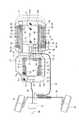
1 and 2 show the configuration of the driving posture adjusting device. FIG. 1 is a side view of an in-vehicle structure provided with a driving posture adjusting device, and FIG. 2 is a plan view of the in-vehicle structure provided with the driving posture adjusting device.
図1及び図2に示すように、運転姿勢調節装置は、大別して、運転者がアクセルペダル31等を操作する際に踵を置くフロアの高さを調整するフロア高さ調整機構10と、車両フロア(固定側フロア)1と個別に構成され、前記フロア高さ調整機構10、アクセルペダル31及びブレーキペダル32が取り付けられている可動フロア33と、可動フロア33を変位させる可動フロア変位機構40と、運転席シート2の高さを調整するシート高調整機構50と、ステアリング71の位置を調整するステアリング位置調整機構70と、姿勢調節部80とを備えている。 As shown in FIGS. 1 and 2, the driving posture adjusting device is roughly divided into a floor
(可動フロアの構成)
可動フロア33には、フロア高さ調整機構10、アクセルペダル31及びブレーキペダル32が、略正方形板形状の取り付け部33aに取り付けられている。取り付け部33aは、車両フロア1に対して平行に配置されており、その取り付け部33aの後端から支持部33bが斜め後方に迫り上がっている。取り付け部33aの前端部に、アクセルペダル31及びブレーキペダル32が取り付けられており、取り付け部33a上の略中央にフロア高さ調整機構10が取り付けられている。(Configuration of movable floor)
On the
(フロア高さ調整機構の構成)
フロア高さ調整機構10は、一対のリンク部材11,12によって構成されたXリンクにより、運転者が足を置く足載置部13(天板)を昇降する構造をなしている。すなわち、両リンク部材11,12の中間部が、連結軸14により回動可能に連結され、両リンク部材11,12の両端部が、足載置部13及び可動フロア33の取り付け部33aにそれぞれ連結されている。(Configuration of floor height adjustment mechanism)
The floor
具体的には、一方のリンク部材11は、その上端部が、ピン15により足載置部13の前側に車両前後方向に延びて形成されたガイド孔16に連結されるとともに、当該ピン15が当該ガイド孔16に対してスライド可能に連結されており、また、その下端部が、ピン17により取り付け部33aの後端付近に回動自在に連結されている。
また、他方のリンク部材12は、その上端部が、ピン18により足載置部13の後側に回動自在に連結され、その下端部が、ピン19により取り付け部33aの前端付近において車両前後方向に延びて形成されたガイド孔20に連結されるとともに、当該ピン19が当該ガイド孔20に対してスライド可能に連結されている。Specifically, the upper end portion of one
Further, the
そして、フロア高さ調整機構10では、これら一対のリンク部材11,12により構成されるXリンクが左右一組となり、取り付け部33aに対して足載置部13を支持している。また、左右のXリンクで、前記一方のリンク部材11を取り付け部33aに回動自在に支持する各ピン17は、1本の軸21により一体とされている。すなわち、当該軸21の両端に形成したピン17で、左右のXリンクにおけるリンク部材11を取り付け部33aに対して回動自在に支持している。そして、フロア高さ調整機構では、当該軸(以下、回転駆動軸という。)21を駆動手段(例えばモータ、以下、フロア上下動駆動用モータという。)23で回転駆動している。また、フロア上下動駆動用モータ23は、後述するように、姿勢調節部80によりその駆動が制御される。 And in the floor
このように構成されるフロア高さ調整機構10により、Xリンクにより足載置部13が可動フロア33に対して昇降(接離)自在にされるとともに、フロア上下動駆動用モータ23が駆動されて回転駆動軸21が回転されると、その回転駆動軸21の回転方向に応じて、足載置部13が上昇及び下降するようになる。
また、足載置部13の前方であり、当該足載置部13の左右方向で略中央に位置されるように、ブレーキペダル32が取り付け部33aに取り付けられており、さらに、足載置部13の前方左側に位置されるように、アクセルペダル31が取り付け部33aに取り付けられている。The floor
Further, the
アクセルペダル31は、一般的なアクセルペダルと同様に、その下端を支点として、回動自在とされて可動フロア33の取り付け部33aに取り付けられている。アクセルペダル31は、電子スロットルであり、図示しないエンジンと機械的に繋がっていない。エンジンと機械的に繋がっていないことで、アクセルペダル31を自在に移動することができる。 Similar to a general accelerator pedal, the
また、ブレーキペダル32は、一般的なブレーキペダルと同様に、その下端を支点として、回動自在とされて可動フロア33の取り付け部33aに取り付けられている。ブレーキペダル32は、いわゆるバイワイヤー方式を採用して構成されており、フレキシブルなケーブル34により、ブースタ35及びマスタシリンダ36と繋がっている。ブースタ35及びマスタシリンダ36とフレキシブルなケーブル34で繋がっていることで、ブレーキペダル32を自在に移動することができる。
運転者は、これらアクセルペダル31及びブレーキペダル32を踏み込み操作して、車両の制駆動力を調整することができる。The
The driver can adjust the braking / driving force of the vehicle by depressing the
(可動フロア変位機構の構成)
可動フロア変位機構40として、運転者用運転席シート2のシートクッション2a下にスライドレール41aを設けている。スライドレール41aは、左右で1対とされ、車両前後方向に平行に、かつ後端側が高くなるように斜めに配置されている。ここで、シートクッション2aの裏面であり、左右両側に、車両前後方向に平行になるように、略三角形状のフレーム部材41をそれぞれ設けている。このフレーム部材41は、一辺がシートクッション2aの裏面の取り付けられており、これにより、他の一辺41aが車両フロア1に対して傾斜するように位置されている。当該他の一辺41aが、スライドレール41aをなしている。(Configuration of movable floor displacement mechanism)
As the movable
この1対のスライドレール41a上に、可動フロア33の支持部33bの左右両端部が係合されている。そして、スライドレール41a上を支持部33bを移動させる駆動手段(例えばモータ、以下、可動フロア変位駆動用モータという。)42を備えている。可動フロア変位駆動用モータ42は、同期手段43によりフロア上下動駆動用モータ23と同期して駆動される。同期手段43としては、タイミングベルトが挙げられる。タイミングベルトで同期手段43を構成すれば、簡単な構成で同期手段43を実現できる。また、可動フロア変位駆動用モータ42は、後述するように、姿勢調節部80によりその駆動が制御される。 The left and right end portions of the
このように構成される可動フロア変位機構40では、可動フロア変位駆動用モータ42の駆動により、スライドレール41a上を可動フロア33の支持部33bがスライドして移動することになり、可動フロア33が前後方向で移動しながら上下方向にも変位する。これにより、可動フロア33の取り付け部33a上に設けたアクセルペダル31、ブレーキペダル32及びフロア高さ調整機構10が、その可動フロア33とともに移動する。
そして、同期手段43により、可動フロア変位駆動用モータ42の駆動に同期してフロア上下動駆動用モータ23を駆動することで、そのような可動フロア33の変位に同期して、足載置部13が上昇及び下降する。In the movable
Then, the synchronization means 43 drives the floor vertical
(シート高調整機構の構成)
シート高調整機構50は、フロア高さ調整機構10と同様な構成として、一対のリンク部材によって構成されたXリンクにより運転席シート2を昇降する構造をなしている。すなわち、両リンク部材51,52の中間部が、連結軸53により回動可能に連結され、両リンク部材51,52の両端部が、車両フロア1及びシートクッション2aにそれぞれ連結されている。
具体的には、一方のリンク部材51は、その上端部が、ピン58によりシートクッション2aの裏面の後端部位、具体的には前記フレーム部材41に回動自在にされており、また、その下端部が、ピン56により車両フロア1、具体的には車両フロア1に設けた取り付け部材57に回動自在に連結されている。(Configuration of seat height adjustment mechanism)
The seat
Specifically, the upper end portion of one
また、他方のリンク部材52は、その上端部が、ピン54によりシートクッション2aの裏面の前側に車両前後方向に延びて形成されたガイド孔55、具体的にはフレーム部材41に設けたガイド孔55、に連結されるとともに、当該ピン54が当該ガイド孔55に対してスライド可能に連結されており、また、その下端部が、ピン59により車両フロア1に車両前後方向に延びて形成されたガイド孔60、具体的には車両フロア1に設けた取り付け部材57のガイド孔60に連結されるとともに、当該ピン59が当該ガイド孔60に対してスライド可能に連結されている。 The
そして、シート高調整機構50は、これら一対のリンク部材51,52によるXリンクが左右一組となり、車両フロア1に対して運転席シート2を支持している。そして、シート高調整機構50では、前記他方のリンク部材52を車両フロア1に回転自在に支持するピン59を回転駆動軸59として、駆動手段(例えばモータ、以下、シート上下動駆動用モータという。)61で回転駆動している。すなわち、シート上下動駆動用モータ61を駆動して、当該ピン59をガイド孔60内で移動させている。そして、シート上下動駆動用モータ61は、フロア上下動駆動用モータ23及び可動フロア変位駆動用モータ42と同期して駆動される。また、シート上下動駆動用モータ61は、後述するように、姿勢調節部80によりその駆動が制御される。 The seat
このように構成されるシート高調整機構50では、Xリンクにより運転席シート2が車両前後方向において上下斜め方向に移動する。すなわち、運転席シート2は、車両前方向に移動する場合には上斜め方向に移動し、車両後方向に移動する場合には下斜め方向に移動する。また、シート上下動駆動用モータ61が駆動されて回転駆動軸59が回転されると、その回転駆動軸の回転方向(ガイド孔60内のピン59の移動方向)に応じて、前述のように、運転席シート2が車両前方向に移動しながら上斜め方向に移動し、又は運転席シート2が車両後方向に移動しながら下斜め方向に移動する。また、例えば、フロア上下動駆動用モータ23により移動される足載置部13の移動量に対して、運転席シート2の移動量を多くしている。 In the seat
(ステアリング位置調整機構の構成)
ステアリング位置調整機構70では、ステアリング71を略L字形状のステアリングポスト72の上端に片持ち支持している。ステアリング71は、フレキシブルなケーブル73を介して、操舵輪である前輪74,75に連結される転舵ロッド76と繋がっている。フレキシブルなケーブル73を介して転舵ロッド76と繋がっていることで、ステアリング71を自在に移動させることができる。運転者は、ステアリング71を操作して、前輪74,75を転舵することができる。(Configuration of steering position adjustment mechanism)
In the steering
ステアリングポスト72は、その下端がシートクッション2aの横下に、車両フロア1に対して回動自在に取り付けられている。具体的には、前記シート高調整機構50として車両フロア1側に設けた取り付け部材57に、駆動手段(例えばモータ、以下、ステアリング前後動駆動用モータという。)77を設けており、このステアリング前後動駆動用モータ77の回転駆動軸78にステアリングポスト72の下端を取り付けている。また、ステアリング前後動駆動用モータ77は、後述するように、姿勢調節部80によりその駆動が制御される。 The lower end of the steering
このように構成されるステアリング位置調整機構70では、ステアリング前後動駆動用モータ77の回転駆動軸78を中心としてステアリングポスト72が回動して、ステアリングポスト72の上端に取り付けられているステアリング71が略前後方向に移動するようになっており、ステアリング前後動駆動用モータ77が駆動されて回転駆動軸78が回転されると、その回転駆動軸78の回転方向に応じて、ステアリング71が前後方向に移動する。 In the steering
(姿勢調節部)
姿勢調整部80は、可動フロア変位駆動用モータ42、シート上下動駆動用モータ61及びステアリング前後動駆動用モータ77の各駆動用モータを駆動制御している。
姿勢調節部80には、各種センサ等から、個人情報、自車速、ブレーキ操作状態、操舵角、走行距離及びキー位置状態の各種情報が入力されており、これら各種情報に基づいて、各駆動用モータ42,61,77を駆動制御する。例えば、個人情報は、図示しないキー(鍵)に設けた個人情報記憶部81(図1参照)に記憶されている。また、キー位置状態は、キー位置検出部82により検出しており、その検出値が姿勢調整部80に入力されている。(Attitude adjustment unit)
The
Various information such as personal information, own vehicle speed, brake operation state, steering angle, travel distance, and key position state is input to the
図3は、姿勢調節部80の処理手順を示す。
図3に示すように、処理を開始すると、先ずステップS1において、姿勢調節部80は、キー位置検出部82の検出値に基づいて、キーの位置がエンジン始動位置か否かを判定する。ここで、姿勢調節部80は、キー(鍵)の位置がエンジン始動になると、ステップS2に進む。FIG. 3 shows a processing procedure of the
As shown in FIG. 3, when the process is started, first, in step S <b> 1, the
ステップS2では、姿勢調節部80は、キーの情報に基づいて、個人情報記憶部81から運転者の体格の一要素となる身長(身長データ)hを読み込む。個人情報記憶部81には、キーと個人情報とが対応されて記憶されており、姿勢調節部80は、キーに対応する個人情報として身長hを個人情報記憶部81から読み込む。
続いてステップS3において、姿勢調節部80は、前記ステップS1で読み込んだ自車速が0か否かを判定する。ここで、姿勢調節部80は、自車速が0の場合、車両が停止しているものとして、ステップS4に進み、自車速が0でない場合、車両が走行しているものとして、ステップS9に進む。
ステップS4では、姿勢調節部80は、前記ステップS2で読み込んだ身長hに基づいて、ステアリング前後位置Lsl、ペダル前後位置Lpl及びシート高さLhhの各調整部位の値Lsl,Lpl,Lhhを算出する。In step S2, the
Subsequently, in step S3, the
In step S4, the
図4〜図6は、身長hに基づいて各調整部位の値Lsl,Lpl,Lhhを算出するためのテーブル(特性図)を示す。
図4に示すように、ステアリング前後位置Lslは、身長hが小さい領域では一定の小さい値となり、身長hがある値a(例えば1450mm)よりも大きくなると、身長hと比例関係となって車両前方側に増加し、身長hがさらにある値b(例えば1900mm)よりも大きくなると、ある一定の大きい値となる。
また、図5に示すように、ペダル前後位置Lplは、身長hが小さい領域では一定の小さい値となり、身長hがある値a(例えば1450mm)よりも大きくなると、身長hと比例関係となって車両前方側に増加し、身長hがさらにある値b(例えば1900mm)よりも大きくなると、ある一定の大きい値となる。4 to 6 show tables (characteristic diagrams) for calculating the values Lsl, Lpl, and Lhh of each adjustment region based on the height h.
As shown in FIG. 4, the steering front / rear position Lsl is a constant small value in a region where the height h is small, and when the height h is larger than a certain value a (for example, 1450 mm), the steering front / rear position Lsl is proportional to the height h. When the height h is further increased and the height h becomes larger than a certain value b (for example, 1900 mm), a certain large value is obtained.
Further, as shown in FIG. 5, the pedal front-rear position Lpl has a constant small value in the region where the height h is small, and becomes proportional to the height h when the height h is larger than a certain value a (for example, 1450 mm). When the vehicle height increases to the front side of the vehicle and the height h becomes larger than a certain value b (for example, 1900 mm), it becomes a certain large value.
また、図6に示すように、シート高さLhhは、身長hが小さい領域では一定の大きい値となり、身長hがある値a(例えば1450mm)よりも大きくなると、身長hと反比例関係となって下方側に減少し、身長hがさらにある値b(例えば1900mm)よりも大きくなると、ある一定の小さい値となる。
これら図4〜図6を用いて、姿勢調節部80は、前記ステップS1で読み込んだ身長hに対応するステアリング前後位置Lsl、ペダル前後位置Lpl及びシート高さLhhを算出する。Further, as shown in FIG. 6, the seat height Lhh is a constant large value in the region where the height h is small, and becomes inversely proportional to the height h when the height h is greater than a certain value a (for example, 1450 mm). When the height h decreases further and the height h becomes larger than a certain value b (for example, 1900 mm), it becomes a certain small value.
4 to 6, the
続いてステップS5において、姿勢調節部80は、前記ステップS4で算出したステアリング前後位置Lslとなるように、ステアリング前後動駆動用モータ77を駆動制御する。このステアリング前後動駆動用モータ77の駆動制御により、運転者の身長hが高くなるほど、ステアリングポスト72が車両前方側に回動し、ステアリング71が車両前方に位置される。 Subsequently, in step S5, the
続いてステップS6において、姿勢調節部80は、前記ステップS4で算出したペダル前後位置Lplとなるように、可動フロア変位駆動用モータ42を駆動制御する。この可動フロア変位駆動用モータ42の駆動制御により、運転者の身長hが高くなるほど、可動フロア33とともにアクセルペダル31、ブレーキペダル32及びフロア高さ調整機構10が車両前方側に移動する。
続いてステップS7において、姿勢調節部80は、前記ステップS4で算出したシート高さLhhとなるように、シート上下動駆動用モータ61を駆動制御する。このシート上下動駆動用モータ61の駆動制御により、運転者の身長hが高くなるほど、運転席シート2が下方(下斜め後方)に位置される。Subsequently, in step S6, the
Subsequently, in step S7, the
続いてステップS8において、前記ステップS1と同様に、姿勢調節部80は、キーの位置がエンジン始動位置か否かを判定する。ここで、姿勢調節部80は、キーの位置がエンジン始動位置の場合、前記ステップS3に進み、キーの位置がエンジン始動位置でない場合、当該図3に示す処理を終了する(前記ステップS1から再び処理を開始する)。
一方、前記ステップS3で自車速が0でない場合に進むステップS9では、姿勢調節部80は、前記ステップS2で読み込んだ身長hに基づいて、スロットル開度ゲインTG(制御目標値)を算出する。Subsequently, in step S8, as in step S1, the
On the other hand, in step S9, which proceeds when the host vehicle speed is not 0 in step S3, the
図7は、身長hに基づいてスロットル開度ゲインTG(制御目標値)を算出するためのテーブル(特性図)を示す。
図7に示すように、スロットル開度ゲインTGは、身長hが小さい領域では一定の大きい値となり、身長hがある値a(例えば1450mm)よりも大きくなると、身長hと反比例関係となって減少し、身長hがさらにある値b(例えば1900mm)よりも大きくなると、ある一定の小さい値となる。
続いてステップS10において、姿勢調節部80は、前記ステップS9で算出したスロットル開度ゲインTG(制御目標値)となるように、スロットル開度ゲインを調整する。そして、姿勢調節部80は、前記ステップS8に進む。FIG. 7 shows a table (characteristic diagram) for calculating the throttle opening gain TG (control target value) based on the height h.
As shown in FIG. 7, the throttle opening gain TG is a constant large value in the region where the height h is small, and decreases in an inversely proportional relationship with the height h when the height h is greater than a certain value a (for example, 1450 mm). When the height h becomes larger than a certain value b (for example, 1900 mm), it becomes a certain small value.
Subsequently, in step S10, the
(動作)
次に動作を説明する。
キーが始動位置にあり(前記ステップS1)、車両が停止していると(前記ステップS3の判定で“Yes”の場合)、個人情報記憶部81から読み出した身長h(前記ステップS2)に基づいて、ステアリング前後位置Lsl、ペダル前後位置Lpl及びシート高さLhhを算出し、これら各値Lsl,Lpl,Lhhに基づいて、可動フロア変位駆動用モータ42、シート上下動駆動用モータ61及びステアリング前後動駆動用モータ77を駆動する(前記ステップS4〜ステップS7)。ここで、ステアリング前後動駆動用モータ77の駆動により、ステアリング71を前後方向で移動させ、可動フロア変位駆動用モータ42の駆動により、可動フロア33を前後方向で移動させながら、上下方向にも変位させ、かつ足載置部13を昇降させる。このときの可動フロア33は、前記スライドレール41aと同様な勾配をもって、斜め方向に移動する。また、シート上下動駆動用モータ61の駆動により、運転席シート2が昇降する(Operation)
Next, the operation will be described.
When the key is at the start position (step S1) and the vehicle is stopped (“Yes” in the determination of step S3), based on the height h (step S2) read from the personal
このとき、前記図4〜図6に示したテーブルに基づいて各駆動用モータ42,61,77を駆動制御することで、運転者の身長hが高くなるほど、ステアリング71が前方に移動するから、ステアリング71が運転席シート2から遠ざかる。また、運転者の身長hが高くなるほど、アクセルペダル31、ブレーキペダル32及びフロア高さ調整機構10(足載置部13)が可動フロア33と一体となって、運転席シート2(シート座面)に対して下斜め前方に遠ざかるように移動する。また、運転者の身長hが高くなるほど、運転席シート2が下斜め後方に移動する。このとき、可動フロア変位駆動用モータ42とフロア上下動駆動用モータ23とを同期して駆動しているから、可動フロア33の移動に同期して、足載置部13も運転者の身長hが高くなるほど下方に移動する。 At this time, by controlling the driving
図8は、運転者の身長hが低くなるときの、可動フロア33とその可動フロア33上の足載置部13との同期動作を示す。
図8に示すように、可動フロア変位駆動用モータ42とフロア上下動駆動用モータ23とを同期して駆動することで、運転者の身長hが低くなるほど、可動フロア33が上斜め後方(同図に示す矢印A1の方向)に移動するとともに、足載置部13が上昇する。FIG. 8 shows a synchronization operation between the
As shown in FIG. 8, the movable floor
一方、キーが始動位置にあり(前記ステップS1)、車両が走行していると(前記ステップS3の判定で“No”の場合)、前述のような調整動作をすることなく(調整動作を既に開始していればその調整動作を中止して)、個人情報記憶部81から読み出した身長h(前記ステップS2)に基づいて、スロットル開度ゲインTG(制御目標値)を算出するとともに、その算出したスロットル開度ゲインTGにスロットル開度ゲイン(実スロットル開度ゲイン)を調整する(前記ステップS9、ステップS10)。これにより、運転者の身長hが低くなるほど、アクセルペダル31の操作量に対するエンジン出力が大きくなる。 On the other hand, if the key is at the starting position (step S1) and the vehicle is traveling (“No” in the determination of step S3), the adjustment operation as described above is already performed (the adjustment operation has already been performed). If it has started, the adjustment operation is stopped), and the throttle opening gain TG (control target value) is calculated based on the height h (step S2) read from the personal
(作用)
次に作用を説明する。
図9は、運転姿勢調節装置が前述の動作をした場合の運転者の運転姿勢の変化を示す。
図9に示すように、シート上下動駆動用モータ61の駆動による運転席シート2の移動により、シート位置PSET(図1に図示)が、最低位置PSETminと最高位置PSETmaxとの間で変化する。具体的には、前記図6に示すテーブルのようにシート高さLhhを制御することで、シート位置PSETは、運転者の身長hが低くなるほど、最低位置PSETminから、その略上斜め前方にある最高位置PSETmaxまで変化する。これにより、シート位置PSETは、最小の身長hで最高位置PSETmaxとなり、最大の身長hで最低位置PSETminとなる。
なお、シート位置PSETは、運転者のヒップポイント近傍の点、例えば、シートクッション2aとシート背もたれとの接合位置である。(Function)
Next, the operation will be described.
FIG. 9 shows a change in the driving posture of the driver when the driving posture adjusting device performs the above-described operation.
As shown in FIG. 9, the seat position PSET (shown in FIG. 1) ismoved between the lowest position PSETmin and the highest position PSETmax by the movement of the driver's
The seat position PSET is a point in the vicinity of the driver's hip point, for example, a joint position between the
そして、この運転席シート2の移動により、運転者のヒップ位置PHP(図1に図示)が、最低位置PHPminと最高位置PHPmaxとの間で変化する。具体的には、前述のように運転席シート2が移動することで、運転者のヒップ位置PHPは、運転者の身長hが低くなるほど、最低位置PHPminから、その上方向にある最高位置PHPmaxまで変化する。すなわち、ヒップ位置PHPは、最小の身長hで最高位置PHPmaxとなり、最大の身長hで最低位置PHPminとなる。As the
ここで、一般的に、身長hが低くなるほど、体(胴体)の厚さが薄くなるから、前述のように運転者の身長hが低くなるほどシート位置PSETが上斜め前方に移動することで、ヒップ位置PHPは運転者の身長hが低くなると上方向に移動するようになる。
さらに、この運転席シート2が移動しても、運転者の目線位置(アイポイント)PI(図1に図示)は一定である。すなわち、運転者の身長hに関係なく、運転者の目線位置PIは一定位置である。Here, generally, as the height h becomes lower, the thickness of the body (torso) becomes thinner. Therefore, as described above, as the height h of the driver becomes lower, the seat position PSET moves diagonally upward. The hip position PHP moves upward when the height h of the driver is lowered.
Furthermore, moving the driver's seat the
ここで、一般的には、身長hが低くなるほど、座高が低くなるから、運転者の身長hが低くなるほど、前述のように、シート位置PSET又はヒップ位置PHPが上方向に移動することで、運転者の目線位置PIは運転者の身長hに関係なく一定位置になる。
一方、ステアリング前後動駆動用モータ77の駆動により、ステアリングポスト72が下端の支持位置PSPを中心に回動してスアリング71が車両前後方向で移動し、これにより、ステアリング位置PSTL(図1に図示)が、最前方位置PSTLminと最後方位置PSTLmaxとの間で変化する。具体的には、図4に示すテーブルのようにステアリング前後位置Lslを制御することで、ステアリング位置PSTLは、運転者の身長hが低くなるほど、最後方位置PSTLmaxから、その略前方にある最前方位置PSTLminまで変化する。これにより、ステアリング位置PSTLは、最小の身長hで最後方位置PSTLmaxとなり、最大の身長hで最前方位置PSTLminとなる。Here, generally, as the height h becomes lower, the seat height becomes lower. Therefore, as the driver's height h becomes lower, the seat position PSET or the hip position PHP moves upward as described above. in, Looking at position PI of the driver is in a fixed position regardless of the height h of the driver.
On the other hand, by driving the steering rearward
また、可動フロア変位駆動用モータ23とフロア上下動駆動用モータ42とが同期して駆動されて、可動フロア33と足載置部13とが同期して動作することで、運転者のヒール位置PHL(図1に図示)が、最前方かつ最低位置PHLminと最後方かつ最高位置PHLmaxとの間で変化する。具体的には、図5に示すテーブルのようにペダル前後位置Lplを制御することで、運転者のヒール位置PHLは、運転者の身長hが低くなるほど、最前方かつ最低位置PHLminから、その略上斜め後方(図8に示す矢印A2の方向)にある最後方かつ最高位置PHLmaxまで変化する。これにより、ヒール位置PHLは、最小の身長hで最後方かつ最高位置PHLmaxとなり、最大の身長hで最前方かつ最低位置PHLminとなる。In addition, the movable floor
また、このように可動フロア33と足載置部13とが同期して動作することで、アクセルペダル31における運転者の踏力入力位置PT(図1に図示)が、最前方かつ最低位置PTminと最後方かつ最高位置PTmaxとの間で変化する。なお、運転者の踏力入力位置PTは、例えばアクセルペダル31表面に凸部として設けたペダルパッド31aの位置である。Further, since the
具体的には、運転者の踏力入力位置PTは、運転者の身長hが低くなるほど、最前方かつ最低位置PTminから、その略上斜め後方(図8に示す矢印A3の方向)にある最後方かつ最高位置PTmaxまで変化する。これにより、運転者の踏力入力位置PTは、最小の身長hで最後方かつ最高位置PTmaxとなり、最大の身長hで最前方かつ最低位置PTminとなる。Specifically, as the driver's height h decreases, the driver's treading force input positionPT is substantially obliquely rearward (in the direction of arrow A3 shown in FIG. 8) from the foremost and lowest positionPTmin . It changes to the last and highest positionPTmax . Thus, pedal force input positionP T of the driver, the forwardmost and the lowest positionP Tmin at the rearmost and uppermost positionP Tmax, and the maximum height h at the minimum height h.
以上のように、運転者の身長hに応じてアクセルペダル31及び足載置部13等を斜め方向で移動させて、ヒール位置PHL及び踏力入力位置PT、すなわち足の位置を運転者の身長hに応じた位置にする、具体的には、運転者の身長hが低くなるほど、足を運転席シート2に近づけるようにすることで、運転者の身長hの影響を受けない運転し易い運転姿勢にすることができる。As described above, the
また、このとき、可動フロア33(取り付け部33a)に対して足載置部13が昇降するから、運転者の身長hに基づいて、運転者のヒール位置PHLと運転者の踏力入力位置PTとの距離が変化する、具体的には、運転者の身長hが低くなるほど、当該距離が短くなる。すなわち、ヒール位置PHLの移動軌跡(図8に示す矢印A2の方向)と運転者の踏力入力位置PTの移動軌跡(図8に示す矢印A3の方向)とが互いに非平行となり、車両後方になるほど間隔が狭くなることで、運転者の身長hが低くなるほど、運転者のヒール位置PHLと運転者の踏力入力位置PTとの距離が短くなる。これにより、当該距離は、最大の身長hで最大となり、最小の身長hで最小となり、アクセルペダル31上の運転者の踏力の入力位置と足載置部13上で運転者が踵を置く位置との距離を運転者の体格に応じた値になる。At this time, since the
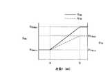
図10は、運転者のヒール位置PHLと運転者の踏力入力位置PTとの距離(以下、第1距離という。)HTHと、運転者のヒール位置PHLと運転者のヒップ位置PHPとの距離(以下、第2距離という。)HHHとの関係を示す。
図10に示すように、第1距離HTHは、運転者の身長hが高くなるほど、最小値HTHminから最大値HTHmaxまで増加する。ここで、最小値HTHmin及び最大値HTHmaxの各値は、図8に示すような値である。また、第2距離HHHも、第1距離HTHと同様に、運転者の身長hが高くなるほど、最小値HHHminから最大値HHHmaxまで増加する。ここで、最小値HHHmin及び最大値HHHmaxの各値は、図8に示すような値である。そして、前述のように、足載置部13の移動量に対して、運転席シート2の移動量を多くしているので、運転者の身長hの変化に対する第2距離H_HHの変化率は、第1距離HTHの変化率よりも大きくなる。10, the distance between the pedal effort input positionP T of the driver's heel positionP HL and the driver (hereinafter, referred to as a firstdistance.) H TH and hip position of the driver's heel positionP HL and the driver P A distance fromHP (hereinafter referred to as a second distance) HHH is shown.
As shown in FIG. 10, the first distance HTH increases from the minimum value HTHmin to the maximum value HTHmax as the height h of the driver increases. Here, each of the minimum value HTHmin and the maximum value HTHmax is a value as shown in FIG. Also, the second distanceH HH, similarly to the first distanceH TH, as height h of the driver increases, increases from a minimum valueH HHmin to a maximum valueH HHmax. Here, the minimum value HHHmin and the maximum value HHHmax are values as shown in FIG. Then, as described above, with respect to the amount of movement of the
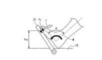
ここで、図11は、運転者がアクセルペダル31を足で踏み込んでいる様子を示す。
図11に示すように、アクセルペダル31を踏力Fで踏み込むとき、足首回りにモーメントMが発生する。例えば、運転者の身長hが低くなると、足が小さくなるから、従来のように、車体フロアの高さが一定だとすれば、アクセルペダルを十分な踏力Fで踏み込もうとすれば、踵を前側に移動し、車体フロアに対して足を立たせるようにしなければならなかった。この結果、足首角度はきつくなってしまう。Here, FIG. 11 shows a state in which the driver steps on the
As shown in FIG. 11, when the
これに対して、本実施形態では、ヒール位置PHLと運転者の踏力入力位置PTとの距離を運転者の体格に応じた値にしており、すなわち、身長hが低くなると、足載置部13の高さが高くなることで、ヒール位置PHLと運転者の踏力入力位置PTとの距離が短くなるから、身長hが小さい運転者でも、身長hが高い者と同様な足首角度で、足首角度がきつくなることなく、アクセルペダル31を踏み込むことができる。すなわち、運転者の身長hの影響を受けない運転し易い姿勢にすることができる。On the other hand, in the present embodiment, the distance between the heel positionPHL and the driver's stepping force input positionPT is set to a value according to the driver's physique, that is, when the height h is lowered, the footrest is placed. Since the distance between the heel positionPHL and the driver's stepping force input positionPT is shortened by increasing the height of the
また、前述のように、フロア高さ調整機構10と可動フロア変位機構40との動作を同期しているので、同時に、運転席シート2の位置と足の位置との関係においても、運転者の身長hの影響を受けない運転し易い運転姿勢にすることができる。
以上のように、運転者の身長hに基づいて、シート位置PSET、運転者の目線位置PI、ステアリング位置PSTL、運転者のヒール位置PHL、運転者の踏力入力位置PTを変化させることで、その運転者の体格に影響されない、運転し易い姿勢(例えば、各体格に対応する基本姿勢)にできる。言い換えれば、運転姿勢調節装置は、運転者の体格に対応した運転し易くなる運転姿勢(例えば、各体格に対応する基本姿勢)になるように、フロア高さ調整機構10、可動フロア変位機構40、シート高調整機構50及びステアリング位置調整機構70を動作させている。Further, as described above, since the operations of the floor
As described above, the seat position PSET , the driver's eye position PI , the steering position PSTL , the driver's heel position PHL , and the driver's treading force input positionPT are changed based on the driver's height h. By doing so, it is possible to make the posture easy to drive without being influenced by the physique of the driver (for example, the basic posture corresponding to each physique). In other words, the driving posture adjusting device has a floor
これにより、運転者の体格に基づく足載置部13及び可動フロア33の制御を、足首関節の角度、膝関節の角度及び股関節の角度のうちの少なくとも一つが運転者の体格にかかわらず一定値になるように行うことで、運転者の体格に影響されない運転し易い姿勢にできる。また、運転者の体格に基づく運転席シート2の高さ方向の位置の制御を、体格に関係なく目線位置が一定位置になるように行うことで、運転者の体格に影響されない運転し易い姿勢にできる。 Thereby, the control of the
また、体格が小さい者は、体格が大きい者と同じペダル操作量にする(エンジン出力を同じにする)には、ペダルパッド位置を踏み込んでいる限り、体格が大きい者と同等の踏力をかけなければならない。しかし、体格が小さい者は、一般的に体力(筋力)も少なく非力であり、大きい体格者と同じ力(踏力)でペダル操作をできたとしても、その負担が大きいと感じる。すなわち、ペダル踏み込み操作時の足首周りのモーメントが体格に関係なく一定値必要だとすると、体格が小さい者はペダル踏み込み操作をきつく(重いと)感じていると考えられる。 Also, a person with a small physique must apply the same pedaling force as a person with a large physique, as long as the pedal pad position is depressed, in order to achieve the same pedal operation amount (with the same engine output) as a person with a large physique. I must. However, a person with a small physique generally has little physical strength (muscle strength) and is weak, and even if the pedal operation can be performed with the same force (stepping force) as a large physique, it feels a heavy burden. That is, if the moment around the ankle when the pedal is depressed requires a constant value regardless of the physique, it is considered that a person with a small physique feels that the pedal depression operation is tight (heavy).
これに対して、運転者の身長hに基づいてスロットル開度ゲインTG(制御目標値)を調整して、運転者の身長hが低くなるほど、アクセルペダル31の操作量に対してエンジン出力が大きくなるように補正しているから、身長hが低い(体格が小さい)運転者でも、少ないペダル操作量で身長hが高い運転者の場合と同等なエンジン出力にすることができるようになり、身長hが高い運転者と同様なアクセルペダル31の操作感覚で同様なエンジン出力にすることができるようになる。すなわち、運転者は、身長hの影響を受けることないアクセルペダル31の操作感覚で、エンジン出力の調整をすることができる。 In contrast, the throttle opening gain TG (control target value) is adjusted based on the driver's height h, and the engine output increases with respect to the operation amount of the
なお、次のような構成により本発明を実現することもできる。
すなわち、前記実施形態では、ヒール位置PHLと運転者の踏力入力位置PTとの距離を運転者の体格に応じて自動制御しているが、運転者が手動で調整可能な調整手段をフロア高さ調整機構10に設けることで、運転者がヒール位置PHLと運転者の踏力入力位置PTとの距離を運転者が手動調整することもできる。これにより、運転者は、自己の体格等に応じてヒール位置PHLと運転者の踏力入力位置PTとの距離を手動調整することができるようになり、所望のペダル操作感覚にすることができる。The present invention can also be realized by the following configuration.
That is, in the above-described embodiment, the distance between the heel positionPHL and the driver's stepping force input positionPT is automatically controlled according to the driver's physique. By providing the
また、前記実施形態では、フロア上下動駆動用モータ23の駆動と可動フロア変位駆動用モータ42の駆動とを同期する同期手段をタイミングベルトとしている。これに対して、他の同期手段、例えば、フロア上下動駆動用モータ23と可動フロア変位駆動用モータ42とをシャフトやケーブルで連結して、これらモータ23,42の駆動を同期することで、簡単な構成で同期手段を実現できる。 Further, in the above-described embodiment, the synchronization means that synchronizes the driving of the floor vertical
また、フロア高さ調整機構10及び可動フロア変位機構40のうちの一方をモータで駆動するようにして、同期手段として、当該モータで駆動されるフロア高さ調整機構10及び可動フロア変位機構40のうちの一方の動作で連動部材を操作して、当該連動部材を介してフロア高さ調整機構10及び可動フロア変位機構40のうちの他方を動作させる。例えば、可動フロア変位機構40(可動フロア33)をモータで駆動する一方で、フロア高さ調整機構10のXリンクを可動フロア33の移動に連動させる連動構造を構築する。この場合、1つのモータでフロア高さ調整機構10及び可動フロア変位機構40を動作させることができるようになるから、簡単な構成でそれら機構10,40を実現できる。 In addition, one of the floor
また、前記実施形態では、足載置部13を移動させて、アクセルペダル31上の運転者による踏力の入力位置とフロア上で運転者が踵を置く位置との距離を変更している。これに対して、アクセルペダル31側を移動させて、アクセルペダル31上の運転者による踏力の入力位置とフロア上で運転者が踵を置く位置との距離を変更する。
また、前記実施形態では、身長hを指標として体格を推定しているが、体格が表出する他の体の特徴、例えば体型に基づいて、体格を推定する。Moreover, in the said embodiment, the
In the embodiment, the physique is estimated using the height h as an index. However, the physique is estimated based on other body characteristics that the physique expresses, for example, the physique.
また、前記実施形態では、アクセルペダル31を運転者が操作する場合の作用及び効果について説明したが、ブレーキペダル32を運転者が操作する場合にも同様な効果を得ることができる。しかし、ブレーキペダル32のストローク量は、アクセルペダル31のストローク量よりも少なく、このようなことから、アクセルペダル31の操作性の方が、ブレーキペダル32の操作性よりも、運転者の体格の影響を受け易くなる。このようなことから、アクセルペダル31側を着目して、ヒール位置PHLと運転者の踏力入力位置PTとの距離を運転者の体格に応じた値にするようにすれば、体格の影響を受けないペダル操作感覚にすることができる効果をより実効あるものにすることができる。Moreover, although the said embodiment demonstrated the effect | action and effect when a driver | operator operates the
また、前記実施形態の説明において、フロア高さ調整機構10は、運転席シートの前下に設置されたペダルと、前記運転席シート及び前記ペダルの間の車体フロア部分との高さ方向の距離を可変にする可変手段を実現しており、姿勢調節部80は、運転者の体格に基づいて、前記可変手段により前記距離を調整する調整手段を実現している。 In the description of the embodiment, the floor
また、可動フロア33(特に取り付け部33a)は、運転席シートの前下に配置されて、前記ペダル、車体フロア部分及び可変手段が取り付けられ、車体側固定部に対して移動自在に支持される被移動部材を実現しており、可動フロア変位機構40は、前記被移動部材を車両前後方向で上下斜め方向に移動させる第1移動手段を実現しており、同期手段43は、前記可変手段による前記ペダルと前記車体フロア部分との高さ方向の距離の変化に同期して、前記第1移動手段による前記上下斜め方向への前記被移動部材の移動を行う同期手段を実現している。
また、シート高調整機構50は、運転席シートを上下方向で移動させ、その移動が前記調整手段により制御される第2移動手段を実現している。The movable floor 33 (particularly the
Further, the seat
(効果)
(1)運転席シートの前下に設置されたペダルと、前記運転席シート及び前記ペダルの間の車体フロア部分との高さ方向の距離を可変にする可変手段と、前記可変手段により前記距離を調整する調整手段と、を備える。これにより、ペダルと車体フロア部分との高さ方向の距離を調整することで、当該距離を運転者の体格、すなわち運転者の足の大きさに応じた距離にすることができる。これにより、運転者の体格の影響を受けないペダル操作感覚にすることができる。(effect)
(1) A variable means for changing a distance in a height direction between a pedal installed in front and under the driver's seat and a vehicle body floor portion between the driver's seat and the pedal; and the distance by the variable means Adjusting means for adjusting. Thus, by adjusting the distance in the height direction between the pedal and the vehicle body floor portion, the distance can be made a distance corresponding to the physique of the driver, that is, the size of the driver's foot. Thereby, it can be set as the pedal operation feeling which is not influenced by a driver's physique.
(2)前記調整手段は、運転者の体格に基づいて、前記距離を制御する。これにより、前記距離を自動的に運転者の体格に基づいた値にすることができる。
(3)前記調整手段は、前記運転者の体格が小さくなるほど前記距離を短くする。これにより、体格の小さい運転者は、踵を前側に突き出して、車体フロアに対して足を立たせる必要がなくなり、体格が大きい運転者と同等な感覚でペダル操作ができる。(2) The adjusting means controls the distance based on a driver's physique. Thereby, the said distance can be automatically made into the value based on a driver | operator's physique.
(3) The adjustment means shortens the distance as the driver's physique becomes smaller. Accordingly, the driver with a small physique does not need to protrude the heel toward the front side and make the foot stand on the vehicle body floor, and can perform the pedal operation with a sense equivalent to that of the driver with a large physique.
(4)運転席シートの前下に配置されて、前記ペダル、車体フロア部分及び可変手段が取り付けられ、車体側固定部に対して移動自在に支持される被移動部材と、前記被移動部材を車両前後方向で上下斜め方向に移動させる第1移動手段と、前記可変手段による前記ペダルと前記車体フロア部分との高さ方向の距離の変化に同期して、前記第1移動手段による前記上下斜め方向への前記被移動部材の移動を行う同期手段と、を備える。これにより、運転者の体格等に応じて、ペダルと車体フロア部分との高さ方向の距離と、ペダルと運転者との間の距離とを、同時に調整することができる。(4) A movable member disposed below the front of the driver's seat, to which the pedal, the vehicle body floor portion, and the variable means are attached and supported movably with respect to the vehicle body side fixing portion; In synchronization with a change in the distance in the height direction between the pedal and the vehicle body floor portion by the variable means, the first moving means for moving the vehicle in the longitudinal direction in the vehicle longitudinal direction, the vertical movement by the first moving means. Synchronization means for moving the member to be moved in the direction. Thereby, according to a driver | operator's physique etc., the distance of the height direction of a pedal and a vehicle body floor part and the distance between a pedal and a driver | operator can be adjusted simultaneously.
(5)前記同期手段は、前記運転者の体格が小さくなるほど、前記距離を短くするとともに、前記被移動部材を上斜め後方に移動させる。これにより、運転者の体格の影響を受けないペダル操作感覚にするとともに、運転者の体格に影響されない運転し易い運転姿勢にできる。
(6)前記可変手段及び前記第1移動手段をそれぞれモータで駆動しており、前記同期手段は、当該各モータの駆動をベルト、回転シャフト又はケーブルを用いて同期させる。これにより、簡単な構成で同期手段を実現できる。(5) The synchronizing means shortens the distance as the driver's physique becomes smaller, and moves the moved member obliquely upward and backward. Thereby, while making it the pedal operation feeling which is not influenced by a driver's physique, it can be made the driving posture which is easy to drive without being influenced by a driver's physique.
(6) The variable means and the first moving means are each driven by a motor, and the synchronizing means synchronizes the driving of each motor using a belt, a rotating shaft or a cable. Thereby, a synchronization means is realizable with a simple structure.
(7)前記可変手段及び前記第1移動手段のうちの一方をモータで駆動しており、前記同期手段は、前記モータで駆動される前記可変手段及び前記第1移動手段のうちの一方の動作で連動部材を操作して、当該連動部材を介して前記可変手段及び前記第1移動手段のうちの他方を動作させる。これにより、簡単な構成で同期手段を実現できる。
(8)前記調整手段は、運転者の体格に対応して運転し易くなる運転姿勢になるように、前記距離を制御するとともに、前記被移動部材を前記上下斜め方向に移動させる。これにより、運転者の体格に影響されない運転し易い運転姿勢にできる。(7) One of the variable means and the first moving means is driven by a motor, and the synchronizing means is an operation of one of the variable means and the first moving means driven by the motor. By operating the interlocking member, the other of the variable means and the first moving means is operated via the interlocking member. Thereby, a synchronization means is realizable with a simple structure.
(8) The adjusting means controls the distance and moves the member to be moved in the up and down diagonal direction so that the driving posture becomes easy to drive corresponding to the physique of the driver. Thereby, it is possible to make the driving posture easy to drive without being influenced by the physique of the driver.
(9)前記調整手段は、前記距離の調整及び前記被移動部材の前記上下斜め方向への移動により、足首関節の角度、膝関節の角度及び股関節の角度のうちの少なくとも一つを運転者の体格に関係なく一定値にする。これにより、運転者の体格に影響されない運転し易い姿勢となる。
(10)運転席シートを上下方向で移動させ、その移動が前記調整手段により制御される第2移動手段を備え、前記調整手段は、前記第2移動手段を制御して、運転者の体格にかかわらず運転者の目線位置を一定位置にする。これにより、運転者の体格に影響されない運転し易い姿勢となる。(9) The adjusting means may adjust at least one of an ankle joint angle, a knee joint angle, and a hip joint angle by adjusting the distance and moving the moved member in the obliquely up and down direction. Regardless of the physique, keep the value constant. As a result, the posture is easy to drive without being affected by the physique of the driver.
(10) The driver seat is moved in the vertical direction, and includes a second moving unit whose movement is controlled by the adjusting unit, and the adjusting unit controls the second moving unit to adjust the physique of the driver. Regardless, the driver's eye position is kept constant. As a result, the posture is easy to drive without being affected by the physique of the driver.
(11)前記ペダルの操作に対して所定のゲインで車両を走行制御しており、運転者の体格に基づいて、前記所定のゲインを変更する。運転者の体格に応じて、ペダルの踏力が異なり、それが走行特性に影響する。このようなことから、運転者の体格に基づいて所定のゲインを変更することで、運転者の体格に影響されない走行特性(制御応答)にできる。
(12)前記運転者の体格が小さくなるほど前記所定のゲインを大きくする。運転者の体格が小さくなるほど、非力になることを考慮することで、運転者の体格に影響されない走行特性(制御応答)にできる。(11) The vehicle is travel-controlled with a predetermined gain in response to the operation of the pedal, and the predetermined gain is changed based on the physique of the driver. Depending on the driver's physique, the pedaling force varies, which affects the driving characteristics. For this reason, by changing the predetermined gain based on the driver's physique, it is possible to achieve a driving characteristic (control response) that is not affected by the driver's physique.
(12) The predetermined gain is increased as the physique of the driver is reduced. Considering that the smaller the driver's physique is, the less powerful it is, the driving characteristics (control response) that are not affected by the physique of the driver can be achieved.
(13)前記ペダルは、車両の駆動力を調整するアクセルペダルである。ブレーキペダルのストローク量は、アクセルペダルのストローク量よりも少なく、このようなことから、アクセルペダルの操作性の方が、ブレーキペダルの操作性よりも、運転者の体格の影響を受け易い。このようなことから、アクセルペダルと車体フロア部分との高さ方向の距離を調整することで、アクセルペダルの操作感覚を運転者の体格の影響を受けないペダル操作感覚にできる。(13) The pedal is an accelerator pedal that adjusts the driving force of the vehicle. The stroke amount of the brake pedal is smaller than the stroke amount of the accelerator pedal. Therefore, the operability of the accelerator pedal is more susceptible to the physique of the driver than the operability of the brake pedal. Therefore, by adjusting the distance in the height direction between the accelerator pedal and the vehicle body floor portion, the operation feeling of the accelerator pedal can be made a pedal operation feeling that is not affected by the physique of the driver.
(14)運転者の体格が変化に基づいて、運転席シートの前下に設置されたペダルと、前記運転席及び前記ペダルの間の車体フロア部分とを相対的に移動させることで、前記ペダル上の運転者による踏力の入力位置と前記車体フロア部分にて運転者が踵を置く位置との距離を前記運転者の体格に応じたものにする。これにより、運転者の体格の影響を受けないペダル操作感覚にすることが可能な運転姿勢調節装置とすることができる。(14) Based on the change in the physique of the driver, the pedal installed in front of the driver's seat and the vehicle floor portion between the driver's seat and the pedal are relatively moved to move the pedal. The distance between the stepping force input position by the upper driver and the position where the driver puts the heel on the vehicle body floor portion is set according to the physique of the driver. Thereby, it can be set as the driving posture adjustment apparatus which can be made into the pedal operation feeling which is not influenced by a driver | operator's physique.
(15)車体フロアと、前記車体フロア上に配置される運転席シートと、前記車体フロア上であり、前記運転席シートの前下に設置されたペダルと、前記ペダルと、前記車体フロアにおける前記運転席シート及び前記ペダルの間の部分との高さ方向の距離を可変にする可変手段と、前記可変手段により前記距離を調整する調整手段と、を備える。これにより、運転席シートに着座した運転者の体格の影響を受けないペダル操作感覚にすることが可能な自動車とすることができる。
(16)運転席シートの前下に設置されたペダルと、前記運転席シート及び前記ペダルの間の車体フロア部分との高さ方向の距離を、運転者の体格に基づいて制御する。これにより、運転者の体格の影響を受けないペダル操作感覚にすることが可能な運転姿勢調節方法とすることができる。(15) A vehicle body floor, a driver seat disposed on the vehicle body floor, a pedal disposed on the vehicle body floor in front and under the driver seat, the pedal, and the pedal in the vehicle body floor Variable means for making the distance in the height direction between the driver's seat and the portion between the pedals variable, and adjusting means for adjusting the distance by the variable means. Thereby, it can be set as the motor vehicle which can be made into the pedal operation feeling which is not influenced by the physique of the driver | operator who seated on the driver's seat.
(16) The distance in the height direction between the pedal installed in front and under the driver seat and the vehicle body floor portion between the driver seat and the pedal is controlled based on the physique of the driver. Thereby, it can be set as the driving posture adjustment method which can be made into the pedal operation feeling which is not influenced by a driver | operator's physique.
1 車両フロア、2 運転席シート、10 フロア高さ調整機構、13 足載置部、23 フロア上下動駆動用モータ、31 アクセルペダル、32 ブレーキペダル、33 可動フロア、40 可動フロア変位機構、42 可動フロア変位駆動用モータ、50 シート高調整機構、61 シート上下動駆動用モータ、70 ステアリング位置調整機構、77 ステアリング前後動駆動用モータ、80 姿勢調節部 DESCRIPTION OF SYMBOLS 1 Vehicle floor, 2 Driver's seat, 10 Floor height adjustment mechanism, 13 Foot placement part, 23 Floor vertical drive motor, 31 Accelerator pedal, 32 Brake pedal, 33 Movable floor, 40 Movable floor displacement mechanism, 42 Movable Floor displacement drive motor, 50 seat height adjustment mechanism, 61 seat vertical movement drive motor, 70 steering position adjustment mechanism, 77 steering forward / backward movement drive motor, 80 attitude adjustment unit
Claims (16)
Translated fromJapanese前記可変手段により前記距離を調整する調整手段と、
を備えることを特徴とする運転姿勢調節装置。A variable means for varying a distance in a height direction between a pedal installed in front and lower of a driver seat and a vehicle body floor portion between the driver seat and the pedal;
Adjusting means for adjusting the distance by the variable means;
A driving posture adjusting device comprising:
前記車体フロア上に配置される運転席シートと、
前記車体フロア上であり、前記運転席シートの前下に設置されたペダルと、
前記ペダルと、前記車体フロアにおける前記運転席シート及び前記ペダルの間の部分との高さ方向の距離を可変にする可変手段と、
前記可変手段により前記距離を調整する調整手段と、
を備えることを特徴とする自動車。Body floor,
A driver's seat seat disposed on the vehicle body floor;
A pedal on the vehicle body floor and installed in front of the driver seat;
Variable means for varying a distance in a height direction between the pedal and a portion of the vehicle body floor between the driver seat and the pedal;
Adjusting means for adjusting the distance by the variable means;
An automobile characterized by comprising:
Priority Applications (1)
| Application Number | Priority Date | Filing Date | Title |
|---|---|---|---|
| JP2006081198AJP2007253809A (en) | 2006-03-23 | 2006-03-23 | Driving posture adjusting device, automobile and driving posture adjusting method |
Applications Claiming Priority (1)
| Application Number | Priority Date | Filing Date | Title |
|---|---|---|---|
| JP2006081198AJP2007253809A (en) | 2006-03-23 | 2006-03-23 | Driving posture adjusting device, automobile and driving posture adjusting method |
Publications (1)
| Publication Number | Publication Date |
|---|---|
| JP2007253809Atrue JP2007253809A (en) | 2007-10-04 |
Family
ID=38628477
Family Applications (1)
| Application Number | Title | Priority Date | Filing Date |
|---|---|---|---|
| JP2006081198APendingJP2007253809A (en) | 2006-03-23 | 2006-03-23 | Driving posture adjusting device, automobile and driving posture adjusting method |
Country Status (1)
| Country | Link |
|---|---|
| JP (1) | JP2007253809A (en) |
Cited By (40)
| Publication number | Priority date | Publication date | Assignee | Title |
|---|---|---|---|---|
| JP2009143457A (en)* | 2007-12-14 | 2009-07-02 | Kanto Auto Works Ltd | Sitting position adjusting device |
| CN106184366A (en)* | 2015-05-29 | 2016-12-07 | 操纵技术Ip控股公司 | Steering assembly |
| CN106256651A (en)* | 2015-06-16 | 2016-12-28 | 操纵技术Ip控股公司 | Regracting steering column assembly and method |
| US10029676B2 (en) | 2014-01-29 | 2018-07-24 | Steering Solutions Ip Holding Corporation | Hands on steering wheel detect |
| US10029725B2 (en) | 2015-12-03 | 2018-07-24 | Steering Solutions Ip Holding Corporation | Torque feedback system for a steer-by-wire vehicle, vehicle having steering column, and method of providing feedback in vehicle |
| US10112639B2 (en) | 2015-06-26 | 2018-10-30 | Steering Solutions Ip Holding Corporation | Vehicle steering arrangement and method of making same |
| US10144383B2 (en) | 2016-09-29 | 2018-12-04 | Steering Solutions Ip Holding Corporation | Steering wheel with video screen and airbag |
| US10160473B2 (en) | 2016-09-13 | 2018-12-25 | Steering Solutions Ip Holding Corporation | Steering column decoupling system |
| US10160477B2 (en) | 2016-08-01 | 2018-12-25 | Steering Solutions Ip Holding Corporation | Electric power steering column assembly |
| US10160472B2 (en) | 2015-10-20 | 2018-12-25 | Steering Solutions Ip Holding Corporation | Steering column with stationary hub |
| US10189496B2 (en) | 2016-08-22 | 2019-01-29 | Steering Solutions Ip Holding Corporation | Steering assembly having a telescope drive lock assembly |
| US10239552B2 (en) | 2016-10-14 | 2019-03-26 | Steering Solutions Ip Holding Corporation | Rotation control assembly for a steering column |
| CN109591590A (en)* | 2017-09-30 | 2019-04-09 | 重庆赫皇科技咨询有限公司 | Twin Rudders automotive control system based on Bluetooth technology |
| US10310605B2 (en) | 2016-11-15 | 2019-06-04 | Steering Solutions Ip Holding Corporation | Haptic feedback for steering system controls |
| US10322682B2 (en) | 2016-03-03 | 2019-06-18 | Steering Solutions Ip Holding Corporation | Steering wheel with keyboard |
| US10343706B2 (en) | 2015-06-11 | 2019-07-09 | Steering Solutions Ip Holding Corporation | Retractable steering column system, vehicle having the same, and method |
| US10351161B2 (en) | 2016-05-27 | 2019-07-16 | Steering Solutions Ip Holding Corporation | Steering column with manual retraction |
| US10351160B2 (en) | 2016-11-30 | 2019-07-16 | Steering Solutions Ip Holding Corporation | Steering column assembly having a sensor assembly |
| US10363958B2 (en) | 2016-07-26 | 2019-07-30 | Steering Solutions Ip Holding Corporation | Electric power steering mode determination and transitioning |
| US10370022B2 (en) | 2017-02-13 | 2019-08-06 | Steering Solutions Ip Holding Corporation | Steering column assembly for autonomous vehicle |
| US10385930B2 (en) | 2017-02-21 | 2019-08-20 | Steering Solutions Ip Holding Corporation | Ball coupling assembly for steering column assembly |
| US10384708B2 (en) | 2016-09-12 | 2019-08-20 | Steering Solutions Ip Holding Corporation | Intermediate shaft assembly for steer-by-wire steering system |
| US10399591B2 (en) | 2016-10-03 | 2019-09-03 | Steering Solutions Ip Holding Corporation | Steering compensation with grip sensing |
| US10421475B2 (en) | 2016-11-15 | 2019-09-24 | Steering Solutions Ip Holding Corporation | Electric actuator mechanism for retractable steering column assembly with manual override |
| US10421476B2 (en) | 2016-06-21 | 2019-09-24 | Steering Solutions Ip Holding Corporation | Self-locking telescope actuator of a steering column assembly |
| US10436299B2 (en) | 2015-06-25 | 2019-10-08 | Steering Solutions Ip Holding Corporation | Stationary steering wheel assembly and method |
| US10442441B2 (en) | 2015-06-15 | 2019-10-15 | Steering Solutions Ip Holding Corporation | Retractable handwheel gesture control |
| US10449927B2 (en) | 2017-04-13 | 2019-10-22 | Steering Solutions Ip Holding Corporation | Steering system having anti-theft capabilities |
| US10457313B2 (en) | 2016-06-28 | 2019-10-29 | Steering Solutions Ip Holding Corporation | ADAS wheel locking device |
| US10481602B2 (en) | 2016-10-17 | 2019-11-19 | Steering Solutions Ip Holding Corporation | Sensor fusion for autonomous driving transition control |
| US10496102B2 (en) | 2016-04-11 | 2019-12-03 | Steering Solutions Ip Holding Corporation | Steering system for autonomous vehicle |
| US10562561B2 (en) | 2016-04-25 | 2020-02-18 | Steering Solutions Ip Holding Corporation | Electrical power steering control using system state predictions |
| US10589774B2 (en) | 2015-05-01 | 2020-03-17 | Steering Solutions Ip Holding Corporation | Counter rotation steering wheel |
| US10766518B2 (en) | 2015-06-25 | 2020-09-08 | Steering Solutions Ip Holding Corporation | Rotation control system for a steering wheel and method |
| US10780915B2 (en) | 2016-12-07 | 2020-09-22 | Steering Solutions Ip Holding Corporation | Vehicle steering system having a user experience based automated driving to manual driving transition system and method |
| US10800445B2 (en) | 2017-11-20 | 2020-10-13 | Steering Solutions Ip Holding Corporation | Vision based active steering system |
| US10875566B2 (en) | 2018-03-22 | 2020-12-29 | Steering Solutions Ip Holding Corporation | Stow release assembly for a manually adjustable steering column assembly |
| US10974756B2 (en) | 2018-07-31 | 2021-04-13 | Steering Solutions Ip Holding Corporation | Clutch device latching system and method |
| CN114912206A (en)* | 2022-06-06 | 2022-08-16 | 岚图汽车科技有限公司 | Design method and design device for automobile seat foot rest and electronic equipment |
| US11560169B2 (en) | 2015-06-11 | 2023-01-24 | Steering Solutions Ip Holding Corporation | Retractable steering column system and method |
- 2006
- 2006-03-23JPJP2006081198Apatent/JP2007253809A/enactivePending
Cited By (43)
| Publication number | Priority date | Publication date | Assignee | Title |
|---|---|---|---|---|
| JP2009143457A (en)* | 2007-12-14 | 2009-07-02 | Kanto Auto Works Ltd | Sitting position adjusting device |
| US10029676B2 (en) | 2014-01-29 | 2018-07-24 | Steering Solutions Ip Holding Corporation | Hands on steering wheel detect |
| US10589774B2 (en) | 2015-05-01 | 2020-03-17 | Steering Solutions Ip Holding Corporation | Counter rotation steering wheel |
| CN106184366A (en)* | 2015-05-29 | 2016-12-07 | 操纵技术Ip控股公司 | Steering assembly |
| US10029724B2 (en) | 2015-05-29 | 2018-07-24 | Steering Solutions Ip Holding Corporation | Steering assembly |
| US11560169B2 (en) | 2015-06-11 | 2023-01-24 | Steering Solutions Ip Holding Corporation | Retractable steering column system and method |
| US10343706B2 (en) | 2015-06-11 | 2019-07-09 | Steering Solutions Ip Holding Corporation | Retractable steering column system, vehicle having the same, and method |
| US10442441B2 (en) | 2015-06-15 | 2019-10-15 | Steering Solutions Ip Holding Corporation | Retractable handwheel gesture control |
| CN106256651A (en)* | 2015-06-16 | 2016-12-28 | 操纵技术Ip控股公司 | Regracting steering column assembly and method |
| US10577009B2 (en) | 2015-06-16 | 2020-03-03 | Steering Solutions Ip Holding Corporation | Retractable steering column assembly and method |
| US10766518B2 (en) | 2015-06-25 | 2020-09-08 | Steering Solutions Ip Holding Corporation | Rotation control system for a steering wheel and method |
| US10436299B2 (en) | 2015-06-25 | 2019-10-08 | Steering Solutions Ip Holding Corporation | Stationary steering wheel assembly and method |
| US10112639B2 (en) | 2015-06-26 | 2018-10-30 | Steering Solutions Ip Holding Corporation | Vehicle steering arrangement and method of making same |
| US10160472B2 (en) | 2015-10-20 | 2018-12-25 | Steering Solutions Ip Holding Corporation | Steering column with stationary hub |
| US10029725B2 (en) | 2015-12-03 | 2018-07-24 | Steering Solutions Ip Holding Corporation | Torque feedback system for a steer-by-wire vehicle, vehicle having steering column, and method of providing feedback in vehicle |
| US10322682B2 (en) | 2016-03-03 | 2019-06-18 | Steering Solutions Ip Holding Corporation | Steering wheel with keyboard |
| US10496102B2 (en) | 2016-04-11 | 2019-12-03 | Steering Solutions Ip Holding Corporation | Steering system for autonomous vehicle |
| US10562561B2 (en) | 2016-04-25 | 2020-02-18 | Steering Solutions Ip Holding Corporation | Electrical power steering control using system state predictions |
| US10351161B2 (en) | 2016-05-27 | 2019-07-16 | Steering Solutions Ip Holding Corporation | Steering column with manual retraction |
| US10421476B2 (en) | 2016-06-21 | 2019-09-24 | Steering Solutions Ip Holding Corporation | Self-locking telescope actuator of a steering column assembly |
| US10457313B2 (en) | 2016-06-28 | 2019-10-29 | Steering Solutions Ip Holding Corporation | ADAS wheel locking device |
| US10363958B2 (en) | 2016-07-26 | 2019-07-30 | Steering Solutions Ip Holding Corporation | Electric power steering mode determination and transitioning |
| US10160477B2 (en) | 2016-08-01 | 2018-12-25 | Steering Solutions Ip Holding Corporation | Electric power steering column assembly |
| US10189496B2 (en) | 2016-08-22 | 2019-01-29 | Steering Solutions Ip Holding Corporation | Steering assembly having a telescope drive lock assembly |
| US10384708B2 (en) | 2016-09-12 | 2019-08-20 | Steering Solutions Ip Holding Corporation | Intermediate shaft assembly for steer-by-wire steering system |
| US10160473B2 (en) | 2016-09-13 | 2018-12-25 | Steering Solutions Ip Holding Corporation | Steering column decoupling system |
| US10144383B2 (en) | 2016-09-29 | 2018-12-04 | Steering Solutions Ip Holding Corporation | Steering wheel with video screen and airbag |
| US10399591B2 (en) | 2016-10-03 | 2019-09-03 | Steering Solutions Ip Holding Corporation | Steering compensation with grip sensing |
| US10676126B2 (en) | 2016-10-14 | 2020-06-09 | Steering Solutions Ip Holding Corporation | Rotation control assembly for a steering column |
| US10239552B2 (en) | 2016-10-14 | 2019-03-26 | Steering Solutions Ip Holding Corporation | Rotation control assembly for a steering column |
| US10481602B2 (en) | 2016-10-17 | 2019-11-19 | Steering Solutions Ip Holding Corporation | Sensor fusion for autonomous driving transition control |
| US10421475B2 (en) | 2016-11-15 | 2019-09-24 | Steering Solutions Ip Holding Corporation | Electric actuator mechanism for retractable steering column assembly with manual override |
| US10310605B2 (en) | 2016-11-15 | 2019-06-04 | Steering Solutions Ip Holding Corporation | Haptic feedback for steering system controls |
| US10351160B2 (en) | 2016-11-30 | 2019-07-16 | Steering Solutions Ip Holding Corporation | Steering column assembly having a sensor assembly |
| US10780915B2 (en) | 2016-12-07 | 2020-09-22 | Steering Solutions Ip Holding Corporation | Vehicle steering system having a user experience based automated driving to manual driving transition system and method |
| US10370022B2 (en) | 2017-02-13 | 2019-08-06 | Steering Solutions Ip Holding Corporation | Steering column assembly for autonomous vehicle |
| US10385930B2 (en) | 2017-02-21 | 2019-08-20 | Steering Solutions Ip Holding Corporation | Ball coupling assembly for steering column assembly |
| US10449927B2 (en) | 2017-04-13 | 2019-10-22 | Steering Solutions Ip Holding Corporation | Steering system having anti-theft capabilities |
| CN109591590A (en)* | 2017-09-30 | 2019-04-09 | 重庆赫皇科技咨询有限公司 | Twin Rudders automotive control system based on Bluetooth technology |
| US10800445B2 (en) | 2017-11-20 | 2020-10-13 | Steering Solutions Ip Holding Corporation | Vision based active steering system |
| US10875566B2 (en) | 2018-03-22 | 2020-12-29 | Steering Solutions Ip Holding Corporation | Stow release assembly for a manually adjustable steering column assembly |
| US10974756B2 (en) | 2018-07-31 | 2021-04-13 | Steering Solutions Ip Holding Corporation | Clutch device latching system and method |
| CN114912206A (en)* | 2022-06-06 | 2022-08-16 | 岚图汽车科技有限公司 | Design method and design device for automobile seat foot rest and electronic equipment |
Similar Documents
| Publication | Publication Date | Title |
|---|---|---|
| JP2007253809A (en) | Driving posture adjusting device, automobile and driving posture adjusting method | |
| CN111591175B (en) | Occupant posture adjustment device and pedal device | |
| RU2686283C1 (en) | Seat for vehicle | |
| JP2010073143A (en) | Pedal device for vehicle | |
| JPH0796784A (en) | Driving attitude adjuster of vehicle | |
| JP2007253808A (en) | Driving posture adjusting device, automobile and driving posture adjusting method | |
| JP4501581B2 (en) | Car driving posture adjustment device | |
| JP2008044510A (en) | Driving posture adjusting device, automobile and driving posture adjusting method | |
| JP3174207B2 (en) | Vehicle brake pedal structure | |
| JP3265087B2 (en) | Vehicle driving attitude adjustment device | |
| JP2020013360A (en) | Pedal device | |
| JP6497182B2 (en) | Driving posture adjustment device for autonomous driving vehicle | |
| JP3313476B2 (en) | Vehicle driving attitude adjustment device | |
| JP5521280B2 (en) | Driving attitude adjustment device for vehicle and driving attitude adjustment method for vehicle | |
| JP3265086B2 (en) | Vehicle driving attitude adjustment device | |
| JP4341389B2 (en) | Vehicle driving posture adjustment device | |
| JP4259301B2 (en) | Vehicle driving posture adjustment device | |
| JP4661123B2 (en) | Car driving posture adjustment device | |
| JPH0796787A (en) | Driving attitude adjuster of vehicle | |
| JP2010073141A (en) | Pedal device for vehicle | |
| JPH11296246A (en) | Driving operation device for vehicles | |
| JP2006290099A (en) | Driving posture adjusting apparatus and method | |
| JP2007001499A (en) | Driving posture adjustment device | |
| JP2023008545A (en) | vehicle | |
| KR101551813B1 (en) | Auxiliary Pedal Device |