JP2007252761A - Coin stocker - Google Patents
Coin stockerDownload PDFInfo
- Publication number
- JP2007252761A JP2007252761AJP2006083215AJP2006083215AJP2007252761AJP 2007252761 AJP2007252761 AJP 2007252761AJP 2006083215 AJP2006083215 AJP 2006083215AJP 2006083215 AJP2006083215 AJP 2006083215AJP 2007252761 AJP2007252761 AJP 2007252761A
- Authority
- JP
- Japan
- Prior art keywords
- coin
- holder plate
- coin holder
- plate
- slide member
- Prior art date
- Legal status (The legal status is an assumption and is not a legal conclusion. Google has not performed a legal analysis and makes no representation as to the accuracy of the status listed.)
- Pending
Links
- 230000037431insertionEffects0.000claimsdescription23
- 238000003780insertionMethods0.000claimsdescription23
- 239000000725suspensionSubstances0.000claimsdescription16
- 210000000078clawAnatomy0.000description3
- 230000000903blocking effectEffects0.000description1
- 238000005192partitionMethods0.000description1
- 230000002093peripheral effectEffects0.000description1
- 210000003813thumbAnatomy0.000description1
Images


Landscapes
- Purses, Travelling Bags, Baskets, Or Suitcases (AREA)
Abstract
Description
Translated fromJapanese本発明は、複数のコインを収納して携帯可能としたノートタイプもしくは手帳タイプのコインストッカーに関する。 The present invention relates to a notebook type or notebook type coin stocker which can be carried by storing a plurality of coins.
従来では様々なタイプのコインケースが提案されている。
例えば、特許文献1に開示されているように、細長箱状のケースを仕切板により前側と後側の空間部を形成し、且つ前後それぞれの空間部を側壁によって複数組の収納部とし、前側および後側の各収納部にコインを重合状に収納自在として成るコインケースがある。Conventionally, various types of coin cases have been proposed.
For example, as disclosed in
また、特許文献2に開示されているように、同種のコインをバネ力に抗して厚み方向に重ね合わせて収納するための円筒形空間部がその軸を横方向にして複数個並設され、手動操作によりコインを一枚づつ放出ゲートから放出させるバイク車両取付型のコインケースがある。 Further, as disclosed in
さらに、特許文献3に開示されているように、複数枚のコインを略コ字枠状のカバー内に収納させ、カバー内でコインの片側は保持穴で係合保持され、コインの反対側はバネ作動部で単独で押えられ、上側開口部から一枚のコインを軽く親指で押えてカバーからスライドさせて取り出す1円玉用のコインケースがある。 Further, as disclosed in
さらにまた、特許文献4に開示されているように、円形端面板の周縁から、先端に係止部を有する円弧板片状の挟持片を対向突出させ、円形端面板の挟持片間に係止受部を形成して成るコイン収納可能とした同構造一対の構成体を形成し、一方の構成体の挟持片を他方の構成体の円形端面板の係止受部に係止させることで両構成体を噛合して成るコインケースがある。
しかしながら、これら従来例によると、コインケース自体が袋状タイプ、筒状タイプ、箱状タイプのものが殆どであって、薄型で携帯性のあるノートタイプもしくは手帳タイプのものが存在しない。 However, according to these conventional examples, the coin cases themselves are mostly bag-type, cylindrical-type, and box-type, and there is no notebook type or notebook type that is thin and portable.
しかも、従来のコインケースは、複数のコインが重合状に収納されていてコインの残数が外部から見えないため、携帯中にコインの使用可能枚数があとどのくらいあるかが簡単には認知できない。 In addition, since the conventional coin case stores a plurality of coins in a superposed manner and the remaining number of coins cannot be seen from the outside, it is not easy to recognize how many coins can be used while carrying.
そこで、本発明は、叙上のような従来存した諸事情に鑑み創出されたもので、一般のノートタイプもしくは手帳タイプ等のような薄型タイプとすることで携帯性の向上したコインケースとすることができ、また首に吊り下げたままでもワンタッチで簡単にコインが取り出せるようにし、しかも携帯中にコインの使用可能枚数があとどのくらいあるかが手帳やノートを開くようにして容易に認知できるようにしたコインストッカーを提供することを目的とする。 Therefore, the present invention was created in view of various circumstances existing in the past, and a coin case with improved portability is obtained by using a thin type such as a general notebook type or a notebook type. You can easily take out coins with a single touch even when hanging around your neck, and you can easily recognize how many coins you can use while carrying by opening your notebook or notebook. The purpose is to provide a coin stocker.
上述した課題を解決するため、本発明にあっては、複数のコイン保持穴を備えたコインホルダー板と、該コインホルダー板の前記コイン保持穴側面を塞ぐよう当該コインホルダー板の一端縁側にヒンジ機構を介して回動自在に連結されて成る蓋板と、コインホルダー板側への蓋板の閉じた状態をロックするよう両板相互の開放縁側に設けられたロック機構とを備えて成ることを特徴としている。 In order to solve the above-described problems, in the present invention, a coin holder plate having a plurality of coin holding holes and a hinge on one edge side of the coin holder plate so as to close the side surface of the coin holding hole of the coin holder plate. A lid plate that is pivotally connected via a mechanism, and a lock mechanism provided on the open edge side of the two plates so as to lock the closed state of the lid plate to the coin holder plate side. It is characterized by.
上記構成において、蓋板とコインホルダー板との間に挟持配置されるよう前記ヒンジ機構を介して回動自在に連結されて成る単数もしくは複数の中間コインホルダー板を備えたものとすることができる。 In the above configuration, it may be provided with one or a plurality of intermediate coin holder plates that are rotatably connected via the hinge mechanism so as to be sandwiched between the lid plate and the coin holder plate. .
ヒンジ機構には、蓋板をコインホルダー板に対して開き方向に付勢する発条体を備えたものとすることができる。 The hinge mechanism may be provided with an elongated body that urges the lid plate in the opening direction with respect to the coin holder plate.
ロック機構は、蓋板側に配したスライド進退可能なスライド部材と、該スライド部材の一端に連結片を介して一体突設した係架片と、スライド部材を前進方向に付勢する発条体と、該発条体の付勢力に抗してのスライド部材の退避位置で前記係架片が挿通可能となるようコインホルダー板に設けられた挿通孔部と、発条体の付勢力に任せて当該スライド部材を前進させることで、挿通孔部に挿通されている係架片を係止固定させるよう前記挿通孔部内に設けられた係合段部とを備えたものとすることができる。 The locking mechanism includes a slide member that is slidable and retracted disposed on the lid plate side, a suspension piece that integrally projects from one end of the slide member via a connecting piece, and a ridge that biases the slide member in the forward direction. An insertion hole provided in the coin holder plate so that the suspension piece can be inserted in the retracted position of the slide member against the urging force of the splaying body, and the sliding member's urging force is left to the slide. By moving the member forward, it can be provided with an engaging step provided in the insertion hole so as to lock and fix the suspension piece inserted into the insertion hole.
前記スライド部材の連結片は、中間コインホルダー板の開放縁側に設けた挿通孔部を挿通可能としたものとすることができる。 The connecting piece of the slide member can be inserted through an insertion hole provided on the open edge side of the intermediate coin holder plate.
コインホルダー板には、ネックストラップを着脱自在に取り付け可能とする吊下げ孔部を備えたものとすることができる。 The coin holder plate may be provided with a hanging hole portion that allows the neck strap to be detachably attached.
本発明によれば、一般のノートタイプもしくは手帳タイプ等のような薄型タイプとすることで携帯性の向上したコインケースとすることができ、また、首に吊り下げたままでもワンタッチで簡単にコインが取り出せるようにし、しかも携帯中にコインの使用可能枚数があとどのくらいあるかが手帳やノートを開くようにして容易に認知できる。 According to the present invention, it is possible to make a coin case with improved portability by adopting a thin type such as a general notebook type or a notebook type. Can be taken out, and you can easily recognize how many coins you can use while carrying by opening your notebook or notebook.
すなわち、これは本発明が、複数のコイン保持穴を備えたコインホルダー板と、該コインホルダー板の前記コイン保持穴側面を塞ぐよう当該コインホルダー板の一端縁側にヒンジ機構を介して回動自在に連結されて成る蓋板と、コインホルダー板側への蓋板の閉じた状態をロックするよう両板相互の開放縁側に設けられたロック機構とを備えて成るからであり、これにより、薄型タイプの携帯性の向上したコインストッカーを容易に形成することができる。しかもロック機構を解放させることによって蓋板を手帳やノートのように開くことでコインホルダー板のコイン保持穴側面全体が露見するため携帯中にコインの使用可能枚数があとどのくらいあるかが容易に認知できる。 That is, this is because the present invention is rotatable via a hinge mechanism on a coin holder plate having a plurality of coin holding holes and one end edge side of the coin holder plate so as to close the side surface of the coin holding hole of the coin holder plate. And a lock mechanism provided on the open edge side of the two plates so as to lock the closed state of the cover plate to the coin holder plate side. A coin stocker with improved portability can be easily formed. In addition, by opening the cover plate like a notebook or notebook by releasing the lock mechanism, the entire side of the coin holding hole of the coin holder plate is exposed, so you can easily recognize how many coins you can use while carrying it can.
蓋板とコインホルダー板との間に挟持配置されるよう前記ヒンジ機構を介して回動自在に連結されて成る単数もしくは複数の中間コインホルダー板を備えたので、コイン全体の収容枚数を増やすことができ、またコインホルダー板、中間コインホルダー板それぞれに対し、例えばコインホルダー板には500円玉、中間コインホルダー板には100円玉というようにコインホルダー板、中間コインホルダー板それぞれに対し互いに異なる金額のコインを収納しておくことができる。 Since one or a plurality of intermediate coin holder plates are rotatably connected via the hinge mechanism so as to be sandwiched between the lid plate and the coin holder plate, the number of coins to be accommodated as a whole can be increased. In addition, for each of the coin holder plate and the intermediate coin holder plate, for example, the coin holder plate has a 500 yen coin, the intermediate coin holder plate has a 100 yen coin, etc. You can store coins of different amounts.
ヒンジ機構には、蓋板をコインホルダー板に対して開き方向に付勢する発条体を備えたので、ロック機構を解放させると同時に蓋体をスムーズに開くことができる。 Since the hinge mechanism is provided with the splaying body that urges the lid plate in the opening direction with respect to the coin holder plate, the lid can be opened smoothly at the same time as the lock mechanism is released.
ロック機構は、蓋板側に配したスライド進退可能なスライド部材と、該スライド部材の一端に連結片を介して一体突設した係架片と、スライド部材を前進方向に付勢する発条体と、該発条体の付勢力に抗してのスライド部材の退避位置で前記係架片が挿通可能となるようコインホルダー板に設けられた挿通孔部と、発条体の付勢力に任せて当該スライド部材を前進させることで、挿通孔部に挿通されている係架片を係止固定させるよう前記挿通孔部内に設けられた係合段部とを備えたので、簡単な構成でしかも低コストでもって蓋板を開閉可能とするロック機構を備えたコインストッカーを容易に形成することができる。 The locking mechanism includes a slide member that is slidable and retracted disposed on the lid plate side, a suspension piece that integrally projects from one end of the slide member via a connecting piece, and a ridge that biases the slide member in the forward direction. An insertion hole provided in the coin holder plate so that the suspension piece can be inserted in the retracted position of the slide member against the urging force of the splaying body, and the sliding member's urging force is left to the slide. Since it has an engaging step provided in the insertion hole so as to lock and fix the suspension piece inserted into the insertion hole by advancing the member, it is simple and inexpensive. Therefore, it is possible to easily form a coin stocker having a lock mechanism that can open and close the cover plate.
前記スライド部材の連結片は、中間コインホルダー板の開放縁側に設けた挿通孔部を挿通可能としたので、ロック機構による蓋板のロック状態において、蓋板とコインホルダー板との間での中間コインホルダー板の挟持固定がしっかりとしたものとなる。 Since the connecting piece of the slide member can be inserted through the insertion hole provided on the open edge side of the intermediate coin holder plate, the intermediate portion between the cover plate and the coin holder plate in the locked state of the cover plate by the locking mechanism. The clamping of the coin holder plate will be firm.
コインホルダー板には、ネックストラップを着脱自在に取り付け可能とする吊下げ孔部を備えたので、ネックストラップを首に吊り下げておくことでコインストッカーを紛失させる虞れが無くなり、しかもコインストッカーを首に吊り下げたままでワンタッチで簡単にコインを取り出すことができる。 The coin holder plate has a hanging hole that allows the neck strap to be detachably attached, so there is no risk of losing the coin stocker by hanging the neck strap around the neck. Coins can be easily removed with a single touch while hanging from the neck.
以下、図面を参照して本発明を実施するための最良の一形態を説明する。
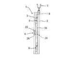
図において示される符号1は、例えば、一般の手帳サイズもしくはノートサイズに形成されたコインストッカーであり、該コインストッカー1は、図1に示すように、複数のコイン保持穴5を備えたコインホルダー板2と、コイン保持穴5側面を塞ぐようにヒンジ機構9を介して閉じられる蓋板3と、コインホルダー板2側への蓋板3の閉じた状態をロックするよう両板2、3相互の開放縁側に設けられたロック機構4とを備えて構成されている。The best mode for carrying out the present invention will be described below with reference to the drawings.
コインホルダー板2は、表面側でコインPとして例えば100円玉6個を3個ずつ縦2列に装着できるようにコインP径に合わせた口径を有する円形状の6個のコイン保持穴5を凹設し、また、各コイン保持穴5の内周面には、装着されるコインPをパッチン止めのように嵌合保持させるための内径方向に突出した複数のヒダ状の爪片部6が形成されている。そして、裏面側からコインPを指先で押し出せるようコインP径よりも小さく且つ指先が入る程度の口径を有する円形状のコイン押出穴7を各コイン保持穴5に同芯状に対応して穿設してある。また、コインホルダー板2の上端側面には、首に吊り下げ可能なネックストラップSを着脱自在に取り付けるための吊下げ孔部8を備えている。 The
ヒンジ機構9は、図1および図2に示すように、コインホルダー板2の一端縁側における上下対称位置にそれぞれ一対にして突設した合計4つの突起10と、これに対応して蓋板3の一端縁側における上下対称位置に突設した合計2つの突起11とのそれぞれに軸孔12が穿設されている。また、コインホルダー板2の上側の両突起10間および下側の両突起10間に、蓋板3の上下の各突起11がそれぞれ軸孔12を合致させた状態で組み込まれ、上側の各突起10、11および下側の各突起10、11それぞれの軸孔12にはヒンジ棒13を嵌挿させてある。これにより、コインホルダー板2のコイン保持穴5側面を塞ぐ方向に蓋板3がヒンジ機構9を介して回動自在に軸支される。 As shown in FIGS. 1 and 2, the
また、このコインホルダー板2の上側および下側における各2つの突起10同士の間隔は、蓋板3の突起11の縦幅よりも若干大きくすることでヒンジ棒13が露出した状態となっており、この露出したヒンジ棒13には、発条体14としての例えば弦巻バネ等のコイル部分を巻装させ、弦巻バネの一端をコインホルダー板2面に係止させ、弦巻バネの他端を蓋板3面に係止させることによって、蓋板3をコインホルダー板2に対して開き方向に付勢されたものとしてある。 Further, the interval between the two
ロック機構4の具体的な構成は、図3に示すように、蓋板3の開放縁側に穿設した上下に長いガイド孔21に沿ってスライド部材22がスライド可能となるように取り付けられ、該スライド部材22の下端にはL字状に折り曲げられた水平な連結片23が形成され、該連結片23の先端には下方に向けてL字状に折り曲げられた係架片24が一体形成されている。 As shown in FIG. 3, the specific structure of the
そして、ガイド孔21は、蓋板3裏面において中間当たりまで塞がって閉塞部25が設けられ、この閉塞部25とスライド部材22とによって囲まれた空間部に形成される。そして、この空間部(ガイド孔21)には、発条体26として例えばコイルスプリングが縦向きとなって介挿されており、該コイルスプリングの上端はガイド孔21の上側内面に当接され、コイルスプリングの下端は連結片23の内側に当接されることで、スライド部材22自体を下方向に常時付勢させるものとしてある。 The
また、蓋板3のガイド孔21の開口部分に対向してコインホルダー板2には挿通孔部27が穿設されており、発条体26の付勢力に抗してのスライド部材22の上方向への退避位置で前記係架片24が挿通孔部27に挿通あるいは脱出可能となるようにしてある。 Further, an
さらに、挿通孔部27内における下側中間部分には係合段部28が形成されており、発条体26の付勢力に任せて当該スライド部材22を下方向に前進させることで、挿通孔部27に挿通されている係架片24が係合段部28に係架されることで、コインホルダー板2側に閉じられた蓋板3がロックされるようにしてある。 Further, an
次に、以上のように構成された最良の形態についての使用、動作の一例について説明する。
先ず、コインホルダー板2の吊下げ孔部8にネックストラップSが取り付けられる。図3(a)および図3(b)に示すように、蓋板3がコインホルダー板2側に閉じられて当該蓋板3がロック機構4によってロックされている状態から、発条体26の付勢力に抗してスライド部材22を上方向へ退避させると、図3(c)および図3(d)に示すように、係架片24が挿通孔部27の係合段部28から外れ、図1に示すように、蓋板3はヒンジ機構9の発条体14による付勢力によってコインホルダー板2に対し開き方向に回動する。Next, an example of use and operation of the best mode configured as described above will be described.
First, the neck strap S is attached to the hanging
そして、コインPの収納に際し、コインホルダー板2のコイン保持穴5にコインPを嵌め込むと爪片部6によって当該コインPは保持される。また、コイン保持穴5からコインPを取り出すときには、コインホルダー板2裏側のコイン押出穴7に指先を押し込むことでコインPが抜き外される。 When the coin P is stored, when the coin P is inserted into the
一方、蓋板3をコインホルダー板2側に閉じてロックする場合には、ロック機構4のスライド部材22を発条体26の付勢力に抗して上方向へ退避させた状態を維持しながら、蓋板3をヒンジ機構9の発条体14による付勢力に抗してコインホルダー板2側に閉じる方向に回動させる。このとき、ロック機構4の係架片24はコインホルダー板2の挿通孔部27に挿通され、スライド部材22を解放させることで当該スライド部材22は発条体26の付勢力に任せて下方向へ復帰前進し、係架片24が係合段部28に係架される。こうしてコインホルダー板2側に閉じられた蓋板3がロックされる。そして、ネックストラップSを首に掛ける等して携帯すれば良い。 On the other hand, when the
また、図4以下にはコインストッカー1の他の構成が示されている。
本構成では、1枚の中間コインホルダー板31を前記ヒンジ機構9を介して回動自在に連結することで、該中間コインホルダー板31を蓋板3とコインホルダー板2との間に挟持配置されるようにしてある。4 and other figures show other configurations of the
In this configuration, one intermediate
すなわち、図4に示すように、コインホルダー板2の一端縁側における上下位置に突設した合計2つの突起10と、この突起10に対して若干ずれた蓋板3の一端縁側における上下位置に突設した合計2つの突起11とのそれぞれに軸孔12が穿設され、コインホルダー板2の上側(下側)の突起10と蓋板3の上側(下側)の突起11とのそれぞれ軸孔12が合致された状態で各突起10、11それぞれの軸孔12にヒンジ棒13を嵌挿させることでヒンジ機構9が形成され、コインホルダー板2のコイン保持穴5側面を塞ぐ方向に蓋板3がヒンジ機構9を介して回動自在となるようにする。 That is, as shown in FIG. 4, a total of two
そして、コインホルダー板2の上側(下側)の突起10と蓋板3の上側(下側)の突起11との間のヒンジ棒13に、中間コインホルダー板31の一端縁側における上下位置に突設した合計2つの突起32の上側(下側)の突起32の軸孔33を嵌装させると共に、中間コインホルダー板31の突起32とコインホルダー板2の突起10との間で露出しているヒンジ棒13に、発条体14としての例えば弦巻バネ等のコイル部分を巻装させ、弦巻バネの一端をコインホルダー板2面に係止させ、弦巻バネの他端を蓋板3面に係止させることによって、蓋板3をコインホルダー板2に対して開き方向に付勢されるものとしてある。このとき、中間コインホルダー板31は、コインホルダー板2と蓋板3とが互いに開いた状態では、両板2、3間で自由に回動できるようにしてある。 Then, the
また、図6に示すように、中間コインホルダー板31の開放縁側には、ロック機構4の位置に対応して挿通孔部34が穿設され、さらにスライド部材22の連結片23は、ロック機構4のスライド部材22を発条体26の付勢力に抗して上方向へ退避させた状態を維持しながらコインホルダー板2と蓋板3とが互いに閉じた際に、この中間コインホルダー板31の挿通孔部34を挿通可能となるように当該連結片23を若干長目に形成してある。ちなみに、コインホルダー板2のコイン挿脱機構およびロック機構4のスライド部材22による蓋板3のロック乃至ロック解除機構は前記した実施の形態と同様である。 As shown in FIG. 6, an
このようにコインホルダー板2と蓋板3との間に中間コインホルダー板31を設けることで、例えばコインホルダー板2には500円玉、中間コインホルダー板31には100円玉というようにコインホルダー板2、中間コインホルダー板31それぞれに対し互いに異なる金額のコインPを収納しておくことができる等のバリエーションが可能となる。 By providing the intermediate
尚、1枚の中間コインホルダー板31とする替わりに、蓋板3とコインホルダー板2との間に2枚以上の中間コインホルダー板31を挟持配置させるようにすることで、コインストッカー1全体を厚みのある冊子状に形成しても良い。 Instead of using one intermediate
P コイン
S ネックストラップ
1 コインストッカー
2 コインホルダー板
3 蓋板
4 ロック機構
5 コイン保持穴
6 爪片部
7 コイン押出穴
8 吊下げ孔部
9 ヒンジ機構
10、11 突起
12 軸孔
13 ヒンジ棒
14 発条体
21 ガイド孔
22 スライド部材
23 連結片
24 係架片
25 閉塞部
26 発条体
27 挿通孔部
28 係合段部
31 中間コインホルダー板
32 突起
33 軸孔
34 挿通孔部P Coin
Claims (6)
Translated fromJapanesePriority Applications (1)
| Application Number | Priority Date | Filing Date | Title |
|---|---|---|---|
| JP2006083215AJP2007252761A (en) | 2006-03-24 | 2006-03-24 | Coin stocker |
Applications Claiming Priority (1)
| Application Number | Priority Date | Filing Date | Title |
|---|---|---|---|
| JP2006083215AJP2007252761A (en) | 2006-03-24 | 2006-03-24 | Coin stocker |
Publications (1)
| Publication Number | Publication Date |
|---|---|
| JP2007252761Atrue JP2007252761A (en) | 2007-10-04 |
Family
ID=38627585
Family Applications (1)
| Application Number | Title | Priority Date | Filing Date |
|---|---|---|---|
| JP2006083215APendingJP2007252761A (en) | 2006-03-24 | 2006-03-24 | Coin stocker |
Country Status (1)
| Country | Link |
|---|---|
| JP (1) | JP2007252761A (en) |
Cited By (2)
| Publication number | Priority date | Publication date | Assignee | Title |
|---|---|---|---|---|
| WO2009041694A1 (en) | 2007-09-27 | 2009-04-02 | Mitsubishi Materials Corporation | ZnO VAPOR DEPOSITION MATERIAL, PROCESS FOR PRODUCING THE SAME, AND ZnO FILM |
| WO2017148151A1 (en)* | 2016-03-04 | 2017-09-08 | 永德利硅橡胶科技(深圳)有限公司 | Multifunctional wallet |
- 2006
- 2006-03-24JPJP2006083215Apatent/JP2007252761A/enactivePending
Cited By (2)
| Publication number | Priority date | Publication date | Assignee | Title |
|---|---|---|---|---|
| WO2009041694A1 (en) | 2007-09-27 | 2009-04-02 | Mitsubishi Materials Corporation | ZnO VAPOR DEPOSITION MATERIAL, PROCESS FOR PRODUCING THE SAME, AND ZnO FILM |
| WO2017148151A1 (en)* | 2016-03-04 | 2017-09-08 | 永德利硅橡胶科技(深圳)有限公司 | Multifunctional wallet |
Similar Documents
| Publication | Publication Date | Title |
|---|---|---|
| KR100906167B1 (en) | Lid opening and closing device | |
| US7325682B2 (en) | Storage case having cover of two slidably-related portions | |
| WO2012067029A1 (en) | Electronic device holder | |
| US20080165486A1 (en) | Computer front bezel | |
| TW201421821A (en) | Card connector and electronic device using the same | |
| CN102647924A (en) | Card Holder | |
| JP2007252761A (en) | Coin stocker | |
| JP2009032595A (en) | Battery pack housing structure of portable electronic device case | |
| CN218432716U (en) | Tool box | |
| JP5012501B2 (en) | Opening / closing lid locking device | |
| KR101263921B1 (en) | Usb device having card-shaped body | |
| JP2000224285A (en) | On-vehicle portable telephone set holder | |
| JP3151947U (en) | Card holder | |
| JP2008029657A (en) | Coin stocker | |
| CN218988223U (en) | Printer paper box and printer | |
| JP2010148641A (en) | Card case | |
| CN204028776U (en) | A container assembly and casing | |
| JP2011178434A (en) | Slide type container | |
| JP5145572B2 (en) | Storage case | |
| JPH11191023A (en) | Portable information device having removable pack-like device | |
| KR200345041Y1 (en) | Portable case for cassette tape | |
| JP2008214853A (en) | Key management tool | |
| JP2010138653A (en) | Portable safe | |
| KR200252976Y1 (en) | A receipt case having locking device | |
| JP5552577B2 (en) | Coin purse |