JP2007252448A - Endoscope insertion part - Google Patents
Endoscope insertion partDownload PDFInfo
- Publication number
- JP2007252448A JP2007252448AJP2006077915AJP2006077915AJP2007252448AJP 2007252448 AJP2007252448 AJP 2007252448AJP 2006077915 AJP2006077915 AJP 2006077915AJP 2006077915 AJP2006077915 AJP 2006077915AJP 2007252448 AJP2007252448 AJP 2007252448A
- Authority
- JP
- Japan
- Prior art keywords
- connecting shaft
- flexible tube
- optical fiber
- treatment instrument
- fiber bundle
- Prior art date
- Legal status (The legal status is an assumption and is not a legal conclusion. Google has not performed a legal analysis and makes no representation as to the accuracy of the status listed.)
- Withdrawn
Links
Images


Classifications
- A—HUMAN NECESSITIES
- A61—MEDICAL OR VETERINARY SCIENCE; HYGIENE
- A61B—DIAGNOSIS; SURGERY; IDENTIFICATION
- A61B1/00—Instruments for performing medical examinations of the interior of cavities or tubes of the body by visual or photographical inspection, e.g. endoscopes; Illuminating arrangements therefor
- A61B1/005—Flexible endoscopes
- A61B1/0051—Flexible endoscopes with controlled bending of insertion part
- A61B1/0055—Constructional details of insertion parts, e.g. vertebral elements
- A—HUMAN NECESSITIES
- A61—MEDICAL OR VETERINARY SCIENCE; HYGIENE
- A61B—DIAGNOSIS; SURGERY; IDENTIFICATION
- A61B1/00—Instruments for performing medical examinations of the interior of cavities or tubes of the body by visual or photographical inspection, e.g. endoscopes; Illuminating arrangements therefor
- A61B1/06—Instruments for performing medical examinations of the interior of cavities or tubes of the body by visual or photographical inspection, e.g. endoscopes; Illuminating arrangements therefor with illuminating arrangements
- A61B1/07—Instruments for performing medical examinations of the interior of cavities or tubes of the body by visual or photographical inspection, e.g. endoscopes; Illuminating arrangements therefor with illuminating arrangements using light-conductive means, e.g. optical fibres
- A—HUMAN NECESSITIES
- A61—MEDICAL OR VETERINARY SCIENCE; HYGIENE
- A61B—DIAGNOSIS; SURGERY; IDENTIFICATION
- A61B1/00—Instruments for performing medical examinations of the interior of cavities or tubes of the body by visual or photographical inspection, e.g. endoscopes; Illuminating arrangements therefor
- A61B1/012—Instruments for performing medical examinations of the interior of cavities or tubes of the body by visual or photographical inspection, e.g. endoscopes; Illuminating arrangements therefor characterised by internal passages or accessories therefor
- A61B1/015—Control of fluid supply or evacuation
- G—PHYSICS
- G02—OPTICS
- G02B—OPTICAL ELEMENTS, SYSTEMS OR APPARATUS
- G02B23/00—Telescopes, e.g. binoculars; Periscopes; Instruments for viewing the inside of hollow bodies; Viewfinders; Optical aiming or sighting devices
- G02B23/24—Instruments or systems for viewing the inside of hollow bodies, e.g. fibrescopes
- G02B23/2476—Non-optical details, e.g. housings, mountings, supports
Landscapes
- Health & Medical Sciences (AREA)
- Life Sciences & Earth Sciences (AREA)
- Surgery (AREA)
- Biomedical Technology (AREA)
- Medical Informatics (AREA)
- Optics & Photonics (AREA)
- Pathology (AREA)
- Radiology & Medical Imaging (AREA)
- Biophysics (AREA)
- Engineering & Computer Science (AREA)
- Physics & Mathematics (AREA)
- Heart & Thoracic Surgery (AREA)
- Nuclear Medicine, Radiotherapy & Molecular Imaging (AREA)
- Molecular Biology (AREA)
- Animal Behavior & Ethology (AREA)
- General Health & Medical Sciences (AREA)
- Public Health (AREA)
- Veterinary Medicine (AREA)
- Instruments For Viewing The Inside Of Hollow Bodies (AREA)
- Endoscopes (AREA)
Abstract
Translated fromJapaneseDescription
Translated fromJapaneseこの発明は内視鏡の挿入部に関する。 The present invention relates to an insertion portion of an endoscope.
体内に挿入される内視鏡の挿入部は一般に、金属螺旋管に網状管を被覆してその外周に可撓性外皮を被覆した可撓管で外装された構成になっている。しかし、内視鏡使用後に高温高圧蒸気滅菌(オートクレーブ)が行われると金属螺旋管に縮みが発生してしまう場合がある。そこでオートクレーブに対する耐久性を得るためには、短筒状の関節リングを連結軸で回動自在に複数連結した可撓管骨組体を螺旋管に代えて用いるとよい(例えば、特許文献1)。
螺旋管に代えて用いられる可撓管骨組体においては、関節リングが一端側において180°対称位置で連結軸によりその隣の関節リングと回動自在に連結され、他端側において一端側と90°方向を変えた向きの180°対称位置で連結軸によりその隣の関節リングと回動自在に連結されている。 In a flexible tube frame used in place of a helical tube, an articulation ring is pivotally connected to an adjacent articulation ring by a connecting shaft at a 180 ° symmetrical position on one end side, and is connected to one end side on the other end side. It is rotatably connected to the adjacent joint ring by a connecting shaft at a 180 ° symmetrical position with the direction changed.
その結果、図5に示されるように、関節リング91を連結する連結軸92の内側端面が可撓管骨組体の内周部に90°間隔で突出した状態になるので、処置具挿通チャンネル93や照明用光学繊維束94等のような断面積の大きな内蔵物は各連結軸92と連結軸92との間の位置(即ち、連結軸92の位置から45°程度偏位した位置)に挿通配置されている。 As a result, as shown in FIG. 5, the inner end face of the connecting
しかし、上述のような複数の関節リング91が連結軸92で連結された構造の可撓管骨組体を最大限まで屈曲させると、各連結軸92が配置されている方向に比べて連結軸92の位置から45°偏位した方向に大きな角度で(従って小さな曲率半径で)屈曲する。連結軸92の位置から45°偏位した方向では、連結軸92が配置されている二方向(即ち、方向が90°相違する二方向)の最大屈曲角が複合されるからである。 However, when the flexible tubular frame having a structure in which the plurality of
そのため、可撓管骨組体が最大限まで屈曲された時に、送気送水チューブ等に比べて径が大きくて屈曲させると座屈し易い処置具挿通チャンネル93や、小さな曲率半径で繰り返し屈曲されると光学繊維が次第に折損して透過光量が低下してしまう照明用光学繊維束94がカーブの最も内側に位置することになり、それらが短期間でダメージを受けて内視鏡そのものが使用不能になる恐れがあった。 Therefore, when the flexible tube frame is bent to the maximum extent, if it is bent with a diameter larger than that of the air / water supply tube, etc. The
そこで本発明は、螺旋管に代えて関節リングを連結軸で回動自在に複数連結した可撓管骨組体が用いられた内視鏡の挿入部において、各種内蔵物の中で屈曲によるダメージを受け易い処置具挿通チャンネルと照明用光学繊維束が優れた耐久性を得ることができる内視鏡の挿入部を提供することを目的とする。 In view of this, the present invention provides an endoscope insertion portion using a flexible tube frame in which a plurality of articulated rings are rotatably connected by a connecting shaft instead of a helical tube. An object of the present invention is to provide an insertion portion of an endoscope in which a treatment instrument insertion channel that is easy to receive and an optical fiber bundle for illumination can obtain excellent durability.
上記の目的を達成するため、本発明の内視鏡の挿入部は、短筒状の関節リングを一端側において180°対称位置で連結軸によりその隣の関節リングと回動自在に連結すると共に他端側において一端側と90°方向を変えた向きの180°対称位置で連結軸によりその隣の関節リングと回動自在に連結して、回動自在に連結された複数の関節リングにより屈曲自在な可撓管骨組体が形成され、少なくとも処置具挿通チャンネルと照明用光学繊維束とを含む複数の内蔵物が可撓管骨組体内に挿通配置された内視鏡の挿入部において、処置具挿通チャンネルと照明用光学繊維束とを各々、連結軸の内側端面に面する位置又はその近傍位置に配置したものである。 In order to achieve the above object, the insertion portion of the endoscope of the present invention connects a short cylindrical joint ring to the adjacent joint ring by a connecting shaft at a 180 ° symmetrical position on one end side so as to be rotatable. On the other end side, it is pivotally connected to the adjacent joint ring by a connecting shaft at a 180 ° symmetrical position in the direction changed from the one end side by 90 °, and bent by a plurality of joint rings that are rotatably connected. A treatment instrument in an insertion portion of an endoscope in which a flexible flexible frame is formed and a plurality of built-in objects including at least a treatment instrument insertion channel and an optical fiber bundle for illumination are inserted and arranged in the flexible tubular framework. The insertion channel and the optical fiber bundle for illumination are each arranged at a position facing the inner end face of the connecting shaft or a position in the vicinity thereof.
したがって、可撓管骨組体の中心軸線位置と処置具挿通チャンネルの中心位置とを通る直線上又はその近傍位置、及び可撓管骨組体の中心軸線位置と照明用光学繊維束の中心位置とを通る直線上又はその近傍位置に、連結軸が配置されているとよい。 Accordingly, a position on or near a straight line passing through the central axis position of the flexible tube frame and the central position of the treatment instrument insertion channel, and the central axis position of the flexible tube frame and the center position of the optical fiber bundle for illumination are determined. The connecting shaft may be arranged on a straight line passing through or in the vicinity thereof.
本発明によれば、螺旋管に代えて関節リングを連結軸で回動自在に複数連結した可撓管骨組体が用いられた内視鏡の挿入部において、処置具挿通チャンネルと照明用光学繊維束とを各々、連結軸の内側端面に面する位置又はその近傍位置に配置したことにより、各種内蔵物の中で屈曲によるダメージを受け易い処置具挿通チャンネルと照明用光学繊維束が座屈や折損を起こし難くて優れた耐久性を得ることができる。 According to the present invention, a treatment instrument insertion channel and an illumination optical fiber are used in an insertion portion of an endoscope in which a flexible tube frame is used in which a plurality of articulation rings are rotatably connected by a connecting shaft instead of a spiral tube. Each of the bundles is disposed at a position facing the inner end face of the connecting shaft or a position in the vicinity thereof, so that the treatment instrument insertion channel and the optical fiber bundle for illumination that are easily damaged by bending in various built-in components It is difficult to cause breakage, and excellent durability can be obtained.
短筒状の関節リングを一端側において180°対称位置で連結軸によりその隣の関節リングと回動自在に連結すると共に他端側において一端側と90°方向を変えた向きの180°対称位置で連結軸によりその隣の関節リングと回動自在に連結して、回動自在に連結された複数の関節リングにより屈曲自在な可撓管骨組体が形成され、少なくとも処置具挿通チャンネルと照明用光学繊維束とを含む複数の内蔵物が可撓管骨組体内に挿通配置された内視鏡の挿入部において、処置具挿通チャンネルと照明用光学繊維束とを各々、連結軸の内側端面に面する位置又はその近傍位置に配置する。 A short cylindrical joint ring is pivotally connected to the adjacent joint ring by a connecting shaft at a 180 ° symmetric position on one end side, and at the other end side, a 180 ° symmetric position in a direction changed from the one end side by 90 °. With the connecting shaft, it is connected to the adjacent joint ring so as to be rotatable, and a flexible tube frame is formed by a plurality of the rotatably connected joint rings. In the insertion part of the endoscope in which a plurality of built-in objects including the optical fiber bundle are inserted and arranged in the flexible tube frame, the treatment instrument insertion channel and the illumination optical fiber bundle are respectively faced to the inner end surface of the connecting shaft. It is arranged at the position where it is
図面を参照して本発明の実施例を説明する。
図2は内視鏡の全体構成を示しており、体内に挿入される挿入部可撓管10の先端には、遠隔操作によって屈曲させることができる湾曲部2が連結され、観察窓等が配置された先端部本体3が湾曲部2の先端に連結されている。4は、湾曲部2の屈曲操作等を行うための操作ノブ5等が配置された操作部である。Embodiments of the present invention will be described with reference to the drawings.
FIG. 2 shows the overall configuration of the endoscope. The
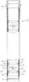
図3は挿入部可撓管10を示しており、この実施例の挿入部可撓管10には、短筒状の関節リング12を例えばリベット状に形成された連結軸13で回動自在に複数(例えば、数十個〜数百個程度)連結して屈曲自在な可撓管骨組体が形成されて、金属細線を編組して形成された網状管14が可撓管骨組体の外周に被覆され、さらにその外周に可撓性外皮15が被覆されている。 FIG. 3 shows an insertion portion
11は、湾曲部2と連結されるように挿入部可撓管10の先端部分に設けられた先端口金、16は、操作部5と連結されるように挿入部可撓管10の後端部分に設けられた後端口金である。なお、挿入部可撓管10内には後述する各種の内蔵物が挿通配置されているが、図3にはその図示が省略されている。 11 is a distal end cap provided at the distal end portion of the insertion portion
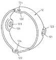
短筒状に形成された各関節リング12は、例えば図4に示されるように、一端側の180°対称位置に一対の舌片121が突出形成され、他端側には一端側と90°異なる向きの180°対称位置に一対の舌片122が突出形成されている。 For example, as shown in FIG. 4, each
そして、複数の関節リング12が軸線を揃えて配置されたときに隣り合う関節リング12の舌片121,122どうしが重なり合うように、一方の舌片121はその肉厚分だけ内方に寄せられて形成され、連結軸13を通すための孔123,124が各舌片121,122に形成されている。 Then, when the plurality of
したがって、各関節リング12は、一端側において180°対称位置でその隣の関節リング12と連結軸13により連結され、他端側において一端側と90°方向を変えた向きの180°対称位置でその隣の関節リング12と連結軸13により連結される。 Accordingly, each
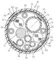
図1は、挿入部可撓管10内に各種内蔵物が挿通配置された状態の断面図(図3におけるI−I断面図)であり、21は撮像信号等を伝送するための電気信号ケーブル、22は二本の照明用光学繊維束であり、各々がシリコンゴムチューブ等により被覆されている。 FIG. 1 is a cross-sectional view (II cross-sectional view in FIG. 3) in which various built-in objects are inserted and arranged in the insertion portion
23は処置具を通すための例えばフッ素樹脂チューブ等からなる処置具挿通チャンネル、24は観察窓の表面に向けて空気/水を送り出すための送気送水チューブ、25は先端部本体3の前方に噴出させる水を送り出すための副送水チューブ、26は湾曲部2を屈曲操作する操作ワイヤを通すための四本のガイドコイルである。これら内蔵物21〜26はいずれも柔軟な可撓性を有している。
そのような電気信号ケーブル21、照明用光学繊維束22、処置具挿通チャンネル23、送気送水チューブ24及び副送水チューブ25は、各々が先端部本体3に先端が固定されて、そこから挿入部可撓管10の軸線と平行方向に偏位することなく真っ直ぐ挿入部可撓管10内に引き通されている。 Such an
また、四本のガイドコイル26は、各々が先端口金11(又は、先端口金11と連結される不図示の湾曲部接続口金)の内周面に固着されていて、そこから挿入部可撓管10の軸線と平行方向に真っ直ぐ挿入部可撓管10内に引き通されている。 Further, each of the four
したがって、各内蔵物21〜26が各々の最先端固定部から偏位することなく真っ直ぐに可撓管骨組体内12,13に引き通されて、図1に示されるように、連結軸13が位置する部分では、処置具挿通チャンネル23と二本の照明用光学繊維束22が各々、連結軸13の内側端面に面する位置又はその近傍位置に配置されている。 Accordingly, each of the built-in
即ち、90°間隔で4ヵ所に位置する連結軸13の中の一つは、可撓管骨組体12,13の中心軸線(即ち関節リング12の中心軸線)位置0と処置具挿通チャンネル23の中心位置とを通る直線X1上に配置され、他の一つの連結軸13は、可撓管骨組体12,13の中心軸線位置0と二本の照明用光学繊維束22のうちの一方の中心位置を通る直線X2上に配置され、さらに他の一つの連結軸13は、可撓管骨組体12,13の中心軸線位置0ともう一つの照明用光学繊維束22の中心位置を通る直線X3の近傍位置に配置されている。 That is, one of the connecting
その結果、挿入部可撓管10に螺旋管に代えて関節リング12を連結軸13で回動自在に複数連結した可撓管骨組体が用いられた内視鏡の挿入部において、挿入部可撓管10が連結軸13に対して45°偏位した方向へ最大屈曲状態まで曲げられた時、各種内蔵物の中で屈曲によるダメージを受け易い処置具挿通チャンネル23と照明用光学繊維束22が、カーブの内側位置に位置しないので座屈や折損が発生し難くて優れた耐久性を得ることができる。 As a result, in the insertion portion of the endoscope in which a flexible tube frame is used in which a plurality of
3 先端部本体
10 挿入部可撓管
12 関節リング(可撓管骨組体)
13 連結軸(可撓管骨組体)
22 照明用光学繊維束(内蔵物)
23 処置具挿通チャンネル(内蔵物)DESCRIPTION OF SYMBOLS 3 Tip part
13 Connecting shaft (flexible tube frame)
22 Optical fiber bundle for illumination (built-in)
23 Treatment instrument insertion channel (built-in)
Claims (2)
Translated fromJapanese上記処置具挿通チャンネルと上記照明用光学繊維束とを各々、上記連結軸の内側端面に面する位置又はその近傍位置に配置したことを特徴とする内視鏡の挿入部。A short cylindrical joint ring is pivotally connected to the adjacent joint ring by a connecting shaft at a 180 ° symmetrical position on one end side, and 180 ° symmetrical in a direction changed 90 ° from the one end side on the other end side. At the position, the joint shaft is pivotally connected to the adjacent joint ring by a connecting shaft, and a flexible tube frame is formed by a plurality of pivotally connected joint rings, and at least the treatment instrument insertion channel and the illumination In an insertion portion of an endoscope in which a plurality of built-in objects including an optical fiber bundle for use are inserted and arranged in the flexible tubular skeleton,
An insertion portion of an endoscope, wherein the treatment instrument insertion channel and the illumination optical fiber bundle are each arranged at a position facing the inner end face of the connecting shaft or in the vicinity thereof.
Priority Applications (3)
| Application Number | Priority Date | Filing Date | Title |
|---|---|---|---|
| JP2006077915AJP2007252448A (en) | 2006-03-22 | 2006-03-22 | Endoscope insertion part |
| US11/688,374US20070225565A1 (en) | 2006-03-22 | 2007-03-20 | Insertion portion of an endoscope |
| DE102007013749ADE102007013749A1 (en) | 2006-03-22 | 2007-03-22 | Insertion part for an endoscope |
Applications Claiming Priority (1)
| Application Number | Priority Date | Filing Date | Title |
|---|---|---|---|
| JP2006077915AJP2007252448A (en) | 2006-03-22 | 2006-03-22 | Endoscope insertion part |
Publications (1)
| Publication Number | Publication Date |
|---|---|
| JP2007252448Atrue JP2007252448A (en) | 2007-10-04 |
Family
ID=38438592
Family Applications (1)
| Application Number | Title | Priority Date | Filing Date |
|---|---|---|---|
| JP2006077915AWithdrawnJP2007252448A (en) | 2006-03-22 | 2006-03-22 | Endoscope insertion part |
Country Status (3)
| Country | Link |
|---|---|
| US (1) | US20070225565A1 (en) |
| JP (1) | JP2007252448A (en) |
| DE (1) | DE102007013749A1 (en) |
Cited By (2)
| Publication number | Priority date | Publication date | Assignee | Title |
|---|---|---|---|---|
| JP2010252859A (en)* | 2009-04-21 | 2010-11-11 | Olympus Corp | Endoscope bending section and manufacturing method of bending tube |
| WO2011034074A1 (en)* | 2009-09-17 | 2011-03-24 | オリンパス株式会社 | Flexible section of an endoscope |
Families Citing this family (36)
| Publication number | Priority date | Publication date | Assignee | Title |
|---|---|---|---|---|
| JP5366575B2 (en)* | 2008-05-08 | 2013-12-11 | Hoya株式会社 | Multiple types of endoscope |
| US8326408B2 (en)* | 2008-06-18 | 2012-12-04 | Green George H | Method and apparatus of neurological feedback systems to control physical objects for therapeutic and other reasons |
| US9713417B2 (en) | 2009-06-18 | 2017-07-25 | Endochoice, Inc. | Image capture assembly for use in a multi-viewing elements endoscope |
| US8926502B2 (en) | 2011-03-07 | 2015-01-06 | Endochoice, Inc. | Multi camera endoscope having a side service channel |
| US12137873B2 (en) | 2009-06-18 | 2024-11-12 | Endochoice, Inc. | Compact multi-viewing element endoscope system |
| US9402533B2 (en) | 2011-03-07 | 2016-08-02 | Endochoice Innovation Center Ltd. | Endoscope circuit board assembly |
| US9642513B2 (en) | 2009-06-18 | 2017-05-09 | Endochoice Inc. | Compact multi-viewing element endoscope system |
| US9492063B2 (en) | 2009-06-18 | 2016-11-15 | Endochoice Innovation Center Ltd. | Multi-viewing element endoscope |
| US10165929B2 (en) | 2009-06-18 | 2019-01-01 | Endochoice, Inc. | Compact multi-viewing element endoscope system |
| US9706903B2 (en) | 2009-06-18 | 2017-07-18 | Endochoice, Inc. | Multiple viewing elements endoscope system with modular imaging units |
| US11547275B2 (en) | 2009-06-18 | 2023-01-10 | Endochoice, Inc. | Compact multi-viewing element endoscope system |
| US9101268B2 (en) | 2009-06-18 | 2015-08-11 | Endochoice Innovation Center Ltd. | Multi-camera endoscope |
| US11278190B2 (en) | 2009-06-18 | 2022-03-22 | Endochoice, Inc. | Multi-viewing element endoscope |
| WO2010146587A1 (en) | 2009-06-18 | 2010-12-23 | Peer Medical Ltd. | Multi-camera endoscope |
| US9872609B2 (en) | 2009-06-18 | 2018-01-23 | Endochoice Innovation Center Ltd. | Multi-camera endoscope |
| US11864734B2 (en) | 2009-06-18 | 2024-01-09 | Endochoice, Inc. | Multi-camera endoscope |
| US9901244B2 (en) | 2009-06-18 | 2018-02-27 | Endochoice, Inc. | Circuit board assembly of a multiple viewing elements endoscope |
| US9101287B2 (en) | 2011-03-07 | 2015-08-11 | Endochoice Innovation Center Ltd. | Multi camera endoscope assembly having multiple working channels |
| US12220105B2 (en) | 2010-06-16 | 2025-02-11 | Endochoice, Inc. | Circuit board assembly of a multiple viewing elements endoscope |
| US9560953B2 (en) | 2010-09-20 | 2017-02-07 | Endochoice, Inc. | Operational interface in a multi-viewing element endoscope |
| EP2618718B1 (en) | 2010-09-20 | 2020-04-15 | EndoChoice Innovation Center Ltd. | Multi-camera endoscope having fluid channels |
| CN103403605A (en) | 2010-10-28 | 2013-11-20 | 恩多巧爱思创新中心有限公司 | Optical systems for multi-sensor endoscopes |
| US12204087B2 (en) | 2010-10-28 | 2025-01-21 | Endochoice, Inc. | Optical systems for multi-sensor endoscopes |
| US11889986B2 (en) | 2010-12-09 | 2024-02-06 | Endochoice, Inc. | Flexible electronic circuit board for a multi-camera endoscope |
| US9320419B2 (en) | 2010-12-09 | 2016-04-26 | Endochoice Innovation Center Ltd. | Fluid channeling component of a multi-camera endoscope |
| CN107361721B (en) | 2010-12-09 | 2019-06-18 | 恩多巧爱思创新中心有限公司 | Flexible electronic circuit boards for multi-camera endoscopes |
| EP2672878B1 (en) | 2011-02-07 | 2017-11-22 | Endochoice Innovation Center Ltd. | Multi-element cover for a multi-camera endoscope |
| CA2798716A1 (en) | 2011-12-13 | 2013-06-13 | Peermedical Ltd. | Removable tip endoscope |
| EP2604172B1 (en) | 2011-12-13 | 2015-08-12 | EndoChoice Innovation Center Ltd. | Rotatable connector for an endoscope |
| US8419720B1 (en) | 2012-02-07 | 2013-04-16 | National Advanced Endoscopy Devices, Incorporated | Flexible laparoscopic device |
| US9560954B2 (en) | 2012-07-24 | 2017-02-07 | Endochoice, Inc. | Connector for use with endoscope |
| US9986899B2 (en) | 2013-03-28 | 2018-06-05 | Endochoice, Inc. | Manifold for a multiple viewing elements endoscope |
| US9993142B2 (en) | 2013-03-28 | 2018-06-12 | Endochoice, Inc. | Fluid distribution device for a multiple viewing elements endoscope |
| US10499794B2 (en) | 2013-05-09 | 2019-12-10 | Endochoice, Inc. | Operational interface in a multi-viewing element endoscope |
| CN103584828B (en)* | 2013-12-02 | 2015-05-13 | 杨幼林 | Multi-pore outer sleeve used for endoscope |
| USD1034977S1 (en) | 2021-07-23 | 2024-07-09 | Ipg Photonics Corporation | Control handle grip for a catheter |
Citations (8)
| Publication number | Priority date | Publication date | Assignee | Title |
|---|---|---|---|---|
| JPS5670750A (en)* | 1979-11-16 | 1981-06-12 | Olympus Optical Co | Flexible tube for endoscope |
| JPS56116442A (en)* | 1980-02-20 | 1981-09-12 | Olympus Optical Co | Endoscope |
| JPS62192134A (en)* | 1986-02-17 | 1987-08-22 | オリンパス光学工業株式会社 | Curved part device for endoscope |
| JPH06181881A (en)* | 1992-12-18 | 1994-07-05 | Olympus Optical Co Ltd | Endoscope |
| JPH0924020A (en)* | 1995-07-10 | 1997-01-28 | Asahi Optical Co Ltd | Flexible tube of endoscope |
| JP2000023908A (en)* | 1998-07-08 | 2000-01-25 | Sony Corp | Articulated curving mechanism |
| JP2000333899A (en)* | 1999-05-28 | 2000-12-05 | Fuji Photo Optical Co Ltd | Curving part structure of endoscope |
| JP2002078674A (en)* | 2000-09-08 | 2002-03-19 | Fuji Photo Optical Co Ltd | Curved surface structure of endoscope |
Family Cites Families (3)
| Publication number | Priority date | Publication date | Assignee | Title |
|---|---|---|---|---|
| US3799151A (en)* | 1970-12-21 | 1974-03-26 | Olympus Optical Co | Controllably bendable tube of an endoscope |
| JP2938486B2 (en)* | 1989-12-28 | 1999-08-23 | 株式会社町田製作所 | Curved tube and manufacturing method thereof |
| JP2987452B2 (en)* | 1990-05-17 | 1999-12-06 | オリンパス光学工業株式会社 | Endoscope |
- 2006
- 2006-03-22JPJP2006077915Apatent/JP2007252448A/ennot_activeWithdrawn
- 2007
- 2007-03-20USUS11/688,374patent/US20070225565A1/ennot_activeAbandoned
- 2007-03-22DEDE102007013749Apatent/DE102007013749A1/ennot_activeWithdrawn
Patent Citations (8)
| Publication number | Priority date | Publication date | Assignee | Title |
|---|---|---|---|---|
| JPS5670750A (en)* | 1979-11-16 | 1981-06-12 | Olympus Optical Co | Flexible tube for endoscope |
| JPS56116442A (en)* | 1980-02-20 | 1981-09-12 | Olympus Optical Co | Endoscope |
| JPS62192134A (en)* | 1986-02-17 | 1987-08-22 | オリンパス光学工業株式会社 | Curved part device for endoscope |
| JPH06181881A (en)* | 1992-12-18 | 1994-07-05 | Olympus Optical Co Ltd | Endoscope |
| JPH0924020A (en)* | 1995-07-10 | 1997-01-28 | Asahi Optical Co Ltd | Flexible tube of endoscope |
| JP2000023908A (en)* | 1998-07-08 | 2000-01-25 | Sony Corp | Articulated curving mechanism |
| JP2000333899A (en)* | 1999-05-28 | 2000-12-05 | Fuji Photo Optical Co Ltd | Curving part structure of endoscope |
| JP2002078674A (en)* | 2000-09-08 | 2002-03-19 | Fuji Photo Optical Co Ltd | Curved surface structure of endoscope |
Cited By (6)
| Publication number | Priority date | Publication date | Assignee | Title |
|---|---|---|---|---|
| JP2010252859A (en)* | 2009-04-21 | 2010-11-11 | Olympus Corp | Endoscope bending section and manufacturing method of bending tube |
| US8939899B2 (en) | 2009-04-21 | 2015-01-27 | Olympus Corporation | Endoscope bending portion and manufacturing method of bending tube |
| WO2011034074A1 (en)* | 2009-09-17 | 2011-03-24 | オリンパス株式会社 | Flexible section of an endoscope |
| JP2011062362A (en)* | 2009-09-17 | 2011-03-31 | Olympus Corp | Curving section of endoscope |
| CN102497801A (en)* | 2009-09-17 | 2012-06-13 | 奥林巴斯株式会社 | Flexible section of an endoscope |
| US8562518B2 (en) | 2009-09-17 | 2013-10-22 | Olympus Corporation | Flexible endoscope part |
Also Published As
| Publication number | Publication date |
|---|---|
| US20070225565A1 (en) | 2007-09-27 |
| DE102007013749A1 (en) | 2007-09-27 |
Similar Documents
| Publication | Publication Date | Title |
|---|---|---|
| JP2007252448A (en) | Endoscope insertion part | |
| JP4477519B2 (en) | Endoscope | |
| EP1867270B1 (en) | Flexible tube for endoscope and endoscope device | |
| US8221312B2 (en) | Endoscope | |
| JP5390048B1 (en) | Endoscope system | |
| US20080214897A1 (en) | Flexible Tube for Endoscope and Endoscope Device | |
| JP2007252447A (en) | Endoscope insertion part | |
| JP2006068393A (en) | Endoscope | |
| JP5325416B2 (en) | Endoscope body and endoscope | |
| JPWO2020070851A1 (en) | Endoscope curved part and endoscope | |
| JPWO2017043124A1 (en) | Endoscope | |
| JP2002209832A (en) | Endoscope | |
| JP2004016725A (en) | Ultrasound endoscope | |
| JP5371822B2 (en) | Endoscope | |
| JP4777005B2 (en) | Endoscope | |
| JP2007054400A (en) | Endoscope | |
| CN211933973U (en) | Endoscope bending part | |
| JP2014108171A (en) | Insertion device and endoscope | |
| WO2019069747A1 (en) | Endoscope curved part and endoscope | |
| JP4355022B2 (en) | Flexible endoscope | |
| JP6091252B2 (en) | Endoscope | |
| JP2003033318A (en) | Intubation endoscope | |
| JP4447123B2 (en) | Endoscope connecting part | |
| JP5459663B2 (en) | Flexible tube bending device | |
| CN109199453B (en) | Ultrasonic endoscope connecting piece and ultrasonic endoscope |
Legal Events
| Date | Code | Title | Description |
|---|---|---|---|
| A711 | Notification of change in applicant | Free format text:JAPANESE INTERMEDIATE CODE: A712 Effective date:20080502 | |
| A621 | Written request for application examination | Free format text:JAPANESE INTERMEDIATE CODE: A621 Effective date:20081205 | |
| A131 | Notification of reasons for refusal | Free format text:JAPANESE INTERMEDIATE CODE: A131 Effective date:20101224 | |
| A761 | Written withdrawal of application | Free format text:JAPANESE INTERMEDIATE CODE: A761 Effective date:20110125 |