JP2007252116A - Pulse charger - Google Patents
Pulse chargerDownload PDFInfo
- Publication number
- JP2007252116A JP2007252116AJP2006073445AJP2006073445AJP2007252116AJP 2007252116 AJP2007252116 AJP 2007252116AJP 2006073445 AJP2006073445 AJP 2006073445AJP 2006073445 AJP2006073445 AJP 2006073445AJP 2007252116 AJP2007252116 AJP 2007252116A
- Authority
- JP
- Japan
- Prior art keywords
- voltage
- unit
- current
- charging
- output
- Prior art date
- Legal status (The legal status is an assumption and is not a legal conclusion. Google has not performed a legal analysis and makes no representation as to the accuracy of the status listed.)
- Withdrawn
Links
Images


Classifications
- H—ELECTRICITY
- H02—GENERATION; CONVERSION OR DISTRIBUTION OF ELECTRIC POWER
- H02J—CIRCUIT ARRANGEMENTS OR SYSTEMS FOR SUPPLYING OR DISTRIBUTING ELECTRIC POWER; SYSTEMS FOR STORING ELECTRIC ENERGY
- H02J7/00—Circuit arrangements for charging or depolarising batteries or for supplying loads from batteries
- H02J7/007—Regulation of charging or discharging current or voltage
- H02J7/00711—Regulation of charging or discharging current or voltage with introduction of pulses during the charging process
Landscapes
- Engineering & Computer Science (AREA)
- Power Engineering (AREA)
- Charge And Discharge Circuits For Batteries Or The Like (AREA)
- Secondary Cells (AREA)
Abstract
Translated fromJapaneseDescription
Translated fromJapanese本発明は、二次電池をパルス充電により充電するパルス充電装置に関し、例えば、携帯機器等の電池パックに内蔵される二次電池のパルス充電装置に関する。 The present invention relates to a pulse charging device that charges a secondary battery by pulse charging, for example, a pulse charging device for a secondary battery built in a battery pack such as a portable device.
繰り返し充放電が可能な蓄電池である二次電池は、携帯機器等の多くの電子機器で使用されている。従来、二次電池のパルス充電装置として、DC/DCコンバータを使用するものや、コストをより低く抑えられるドロッパ方式の定電圧制御回路を用いたものが知られている。 Secondary batteries, which are rechargeable storage batteries, are used in many electronic devices such as portable devices. 2. Description of the Related Art Conventionally, as a secondary battery pulse charging device, one using a DC / DC converter or one using a dropper type constant voltage control circuit capable of reducing the cost is known.
携帯電話機などの携帯機器の場合、外出先で充電が必要になる場合を考慮すると、各種の電源により柔軟に対応できるように、携帯機器の電池パックに充電装置を内蔵させることが望ましい。しかし、DC/DCコンバータを用いた充電装置は、部品点数が多いことから、携帯機器の電池パックのような小さな装置に内蔵させることは困難であり、またコスト高となる。ドロッパ方式の定電圧制御回路を用いる充電装置は、発熱が大きいため、携帯機器の電池パックに内蔵させると他の電子部品に悪影響を及ぼすおそれがある。 In the case of a mobile device such as a mobile phone, it is desirable to incorporate a charging device in the battery pack of the mobile device so that it can be flexibly handled by various power sources in consideration of the need for charging on the go. However, since a charging device using a DC / DC converter has a large number of parts, it is difficult to incorporate the charging device into a small device such as a battery pack of a portable device, and the cost increases. Since a charging device using a dropper type constant voltage control circuit generates a large amount of heat, it may adversely affect other electronic components if it is built in a battery pack of a portable device.
例えば特許文献1には、DC/DCコンバータを用いた充電装置より簡単な構成で、かつドロッパ方式の定電圧制御回路を用いる充電装置より低発熱なパルス充電装置が開示されている。 For example,
図8は、従来のパルス充電装置を含む電池パックを使用した電子機器の構成を示すブロック図である。 FIG. 8 is a block diagram showing a configuration of an electronic device using a battery pack including a conventional pulse charging device.
図8において、10は携帯使用時などバッテリ駆動時に携帯機器20に電源を供給する電池パック、20は負荷回路21を備える携帯機器、30は携帯機器20及び電池パック10に電源を供給するACアダプタ30である。ACアダプタ30は、直流電圧を携帯機器20に供給するとともに、電池パック10へ充電電流を供給する。 In FIG. 8, 10 is a battery pack that supplies power to the
電池パック10は、電池電圧V1,V2,V3を発生する3つのセルB1,B2,B3からなる二次電池11と、二次電池11に供給される充電電流をオン/オフするスイッチ部12と、二次電池11の各セルB1,B2,B3の電圧V1,V2,V3を検出する電池電圧検出部13と、ACアダプタ30の接続を検出するACアダプタ接続検出部14と、電池パック20全体のパルス充電制御及びスイッチ部12のオン/オフを制御するパルス充電制御部15とを備える。 The
パルス充電制御部15は、スイッチ素子等により構成される制御部40と、制御部40の制御に基づいて充電制御電圧を基準電圧として発生する基準電圧発生部41と、電池電圧検出部13の検出結果を基に現在から過去に至る規定の期間内における二次電池11の電池電圧Vbattの平均電池電圧Vbatt_aveを算出し、得られた値と基準電圧とを比較する電圧比較部42と、電圧比較の結果、平均電池電圧Vbatt_aveが充電制御電圧以上となったことをラッチするラッチ部43と、充電周期Tを設定する周期タイマ設定部44と、規定の充電周期Tとオンデューティ比Dとの積によって決定されるオンデューティ時間D×Tを設定するデューティタイマ設定部45とを備えて構成される。 The pulse
充電が開始されると、周期タイマ設定部44により周期Tが、デューティタイマ45によりオンデューティ時間D×Tが設定される。設定した周期Tとオンデューティ時間D×Tにより、スイッチ部12がオン/オフを繰り返し、平均電池電圧Vbatt_aveが基準電圧発生部41により発生する基準電圧以上であることが検出された直後の周期Tからオンデューティ比Dを減少が始まり、オンデューティ比Dが規定値未満になった時点で充電を終了するように動作する。上記構成のパルス充電装置は、DC/DCコンバータを用いたパルス充電装置より簡単な構成で、二次電池11を充電できる。また、供給される電流をオン/オフすることによって充電を制御するので、ドロッパ方式の定電圧制御回路を用いるパルス充電装置に比べてより低発熱で充電できる。
ところで、二次電池に供給する充電電流には、二次電池の種類と電池電圧に応じた適正値が存在している。充電電流が適正値を超えて供給されると、二次電池を劣化させてしまうおそれがある。また、充電電流が適正値を過度に下回ると、充電時間が長くなってしまうという問題がある。 By the way, the charging current supplied to the secondary battery has an appropriate value corresponding to the type of the secondary battery and the battery voltage. If the charging current is supplied exceeding an appropriate value, the secondary battery may be deteriorated. In addition, when the charging current is excessively lower than the appropriate value, there is a problem that the charging time becomes long.
特許文献1記載のパルス充電装置は、安価で発熱が少なく充電時間の短縮が可能であるものの、二次電池の電池電圧の検出結果に基づいて二次電池に供給される充電電流のオン/オフを行っているため、平均充電電流を適正値に一致させるというような充電電流の細やかな制御は難しい。したがって、接続する電源によっては、充電電流が適正値を大幅に上回ってしまい、二次電池を劣化させてしまうおそれがある。 Although the pulse charging device described in
本発明は、かかる点に鑑みてなされたものであり、電池電圧に応じて充電電流を細やかに制御できるパルス充電装置を提供することを目的とする。 This invention is made | formed in view of this point, and it aims at providing the pulse charging device which can control a charging current finely according to a battery voltage.
本発明のパルス充電装置は、直流電流源からの充電電流をオン/オフするスイッチ手段と、前記充電電流を検出する電流検出手段と、前記電流検出手段の出力を平均化する平均化手段と、基準信号を発生する基準信号発生手段と、前記平均化手段の出力と前記基準信号とを比較する比較手段と、前記比較手段の出力に基づいて前記スイッチ手段を制御する制御手段とを備える構成を採る。 The pulse charging device of the present invention comprises a switching means for turning on / off a charging current from a direct current source, a current detecting means for detecting the charging current, and an averaging means for averaging the outputs of the current detecting means, A configuration comprising reference signal generating means for generating a reference signal, comparison means for comparing the output of the averaging means and the reference signal, and control means for controlling the switch means based on the output of the comparison means. take.
本発明のパルス充電装置は、直流電流源からの充電電流をオン/オフするスイッチ手段と、前記充電電流を検出する電流検出手段と、前記電流検出手段の出力を平滑化する電圧平均化手段と、三角波信号を発生する三角波発生手段と、前記電圧平均化手段の出力と前記三角波信号とを比較する比較手段と、前記比較手段の出力に基づいて前記スイッチ手段を制御する制御手段とを備える構成を採る。 The pulse charging apparatus according to the present invention includes a switching unit that turns on / off a charging current from a direct current source, a current detecting unit that detects the charging current, and a voltage averaging unit that smoothes the output of the current detecting unit. A triangular wave generating means for generating a triangular wave signal; a comparing means for comparing the output of the voltage averaging means with the triangular wave signal; and a control means for controlling the switch means based on the output of the comparing means. Take.
より好ましい具体的な態様として、前記比較手段は、ヒステリシス幅を有する比較器からなり、前記基準電圧と前記ヒステリシス幅との間で反転信号を出力し、前記制御手段は、前記比較器からの前記反転信号に基づいて前記スイッチ手段をオン/オフ制御して、前記直流電流源からの充電電流を平均充電電流として定電流化する。 As a more preferable specific aspect, the comparison unit includes a comparator having a hysteresis width, and outputs an inverted signal between the reference voltage and the hysteresis width, and the control unit outputs the inverted signal from the comparator. The switch means is turned on / off based on the inversion signal, and the charging current from the DC current source is made constant as an average charging current.
より好ましい具体的な態様として、前記比較手段は、前記電圧平均化手段により平滑化された信号と前記三角波信号とを比較して反転信号を出力し、前記制御手段は、前記比較器からの前記反転信号に基づいて前記スイッチ手段をオン/オフ制御して、前記直流電流源からの充電電流を平均充電電流として定電流化する。 As a more preferred specific aspect, the comparison means compares the signal smoothed by the voltage averaging means with the triangular wave signal and outputs an inverted signal, and the control means outputs the inverted signal from the comparator. The switch means is turned on / off based on the inversion signal, and the charging current from the DC current source is made constant as an average charging current.
さらに、二次電池の電池電圧を検出する電池電圧検出手段を備え、前記制御手段は、前記電池電圧検出手段により所定の電池電圧が検出されたとき、前記スイッチ手段をオフにする制御を行うことがより好ましい。 Furthermore, the battery voltage detection means for detecting the battery voltage of the secondary battery is provided, and the control means performs control to turn off the switch means when a predetermined battery voltage is detected by the battery voltage detection means. Is more preferable.
本発明によれば、平均充電電流を電池電圧に応じて細かに制御することができ、電池に対し過大な電流を流してしまい電池を劣化させてしまうといった不具合を防止することができる。また、より細かなパルス充電制御が可能になるため、充電時間の短縮が期待できる。また、ドロッパ方式の充電装置に比べ低発熱な充電ができる。 According to the present invention, it is possible to finely control the average charging current according to the battery voltage, and it is possible to prevent a problem that an excessive current flows through the battery and deteriorates the battery. In addition, since finer pulse charge control is possible, a reduction in charge time can be expected. Further, the battery can be charged with lower heat generation than a dropper charging device.
以下、本発明の実施の形態について、図面を参照して詳細に説明する。 Hereinafter, embodiments of the present invention will be described in detail with reference to the drawings.
(実施の形態1)
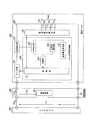
図1は、本発明の実施の形態1に係るパルス充電装置の構成を示すブロック図である。本実施の形態は、パルス充電装置を携帯機器に装着される電池パックに適用した例である。(Embodiment 1)
FIG. 1 is a block diagram showing the configuration of the pulse charging apparatus according to
図1において、100はパルス充電装置を含む電池パック、200は負荷回路201を備える携帯電話機などの携帯機器、300は充電用電源として充電電流Ichgを供給する能力を有するACアダプタである。ACアダプタ300から出力された直流電圧Vinが携帯機器200に供給されるとともに、電池パック100へ充電電流を供給する。 In FIG. 1, 100 is a battery pack including a pulse charging device, 200 is a portable device such as a mobile phone provided with a
ACアダプタ300は、商用AC電源を直流電圧Vinに変換して携帯機器200及び電池パック100に供給する。ACアダプタ300は、携帯機器200及び電池パック100に充電電流Ichgを供給するが、詳細には充電電流Ichgのうち充電電流Ichg1が電池パック100に、充電電流Ichg2が負荷回路201に供給される。本実施の形態は、電池パック100を充電するパルス充電制御に特徴があるため、説明の便宜上充電電流Ichgと充電電流Ichg1とを区別せず、充電電流Ichg1を全て充電電流Ichgとして扱う。 The
電池パック100は、電池電圧V1,V2,V3を発生する3つのセルB1,B2,B3からなる二次電池110と、二次電池110に供給される充電電流をオン/オフするスイッチ部120と、二次電池110の各セルB1,B2,B3の電圧V1,V2,V3を足し合わせた二次電池110の電圧Vbattを検出する電池電圧検出部130と、二次電池110を充電する充電電流を検出する電流検出部140と、電池パック100全体のパルス充電制御及びスイッチ部120のオン/オフを制御するパルス充電制御部150とを備えて構成される。 The
上記スイッチ部120、電池電圧検出部130、電流検出部140、及びパルス充電制御部150は、パルス充電装置160を構成する。 The
パルス充電制御部150は、スイッチ部120のオン/オフを制御する制御部151と、電流検出部140により検出された信号を平均化する平均化部152と、基準電圧を発生する基準電圧発生部153と、平均化部152からの出力信号と基準電圧発生部153からの出力信号を比較する比較部154とを備えて構成される。 The pulse
電池電圧検出部130は、二次電池110の電圧Vbattを検知し、電池電圧が所定の電池電圧まで充電されたことを検出する。 The battery
制御部151は、比較部154からの反転信号に基づいてスイッチ部120をオン/オフ制御して、直流電流源からの充電電流を平均充電電流として定電流化する制御を行う。 The
基準電圧発生部153は、平均充電電流の基準値となる基準電圧を発生する。基準電圧は、制御部151の設定により発生させる基準電圧を可変できることがより好ましい。 The
比較部154は、ヒステリシス幅を有する比較器180(図2で後述する)を備え、基準電圧発生部153からの基準電圧とヒステリシス幅との間で反転信号を出力する。この反転信号を基に出力された信号VGによりパルス制御が行われる。 The
図2は、上記パルス充電装置160の詳細な構成を示す回路図である。 FIG. 2 is a circuit diagram showing a detailed configuration of the
図2において、パルス充電装置160から見てACアダプタ300を外部電源としている。以下、ACアダプタ300を外部電源300と呼ぶ。スイッチ部120は、例えばPMOSトランジスタ191からなり、ソースが外部電源300に接続され、ドレインが二次電池110に接続されるとともに、制御部151の制御信号をゲートに受ける。PMOSトランジスタ191は、制御部151から出力される制御信号によりオン/オフし、外部電源300からの充電電流をオン/オフする。 In FIG. 2, the
電池電圧検出部130は、基準電圧VJを発生する基準電圧発生部131と、基準電圧発生部131から出力される電圧VJと電池電圧VBとを比較する比較器132とから構成される。電池電圧検出部130は、電池電圧VBが充電完了基準電圧VJ以上となった時、比較器132の出力VKが変化し、制御部151は、比較器132の出力VKの変化を受けてスイッチ部120のオン/オフ制御を停止して外部電源300からの充電電流を停止させる。 The battery
電流検出部140は、外部電源300と二次電池110間に挿入された電流検出抵抗Rs、オペアンプからなり電流検出抵抗Rsの外部電源300側の電圧VAをインピーダンス変換するバッファ141、電流検出抵抗Rsの二次電池110側の電圧VBをインピーダンス変換するバッファ142、差動増幅器143、及び抵抗144〜147から構成される。差動増幅器143の抵抗144〜147の抵抗値が同一であれば、差動増幅器143の出力電圧VCは、VAとVBとの差(VA−VB)を出力する。電流検出抵抗Rsの電圧VA,VBをインピーダンス変換して差動増幅器143に入力することで、充電電流への影響を極力抑えた状態で、検出抵抗Rsの両端の電圧差(VA−VB)を検出することができる。 The
パルス充電制御部150は、制御部151、平均化部152、基準電圧VFを発生する基準電圧発生部153、及び比較部154から構成される。 The pulse
平均化部152は、抵抗170とコンデンサ171とからなるCR積分回路であり、電流検出部140の出力電圧VCを平滑化し、電圧VEを出力する。 The averaging
比較部154は、パルスを発生させるためのヒステリシス幅Vhysを有する比較器180からなり、比較器180は、平均化部152の出力電圧VEと基準電圧VFとを比較する。 The
制御部151は、ANDゲート回路181、スイッチ部120のPMOSトランジスタ191をオン/オフするためのNMOSトランジスタ182、及びプルアップ抵抗183から構成される。ANDゲート回路181は、比較部154の比較器180出力信号と電池電圧検出部130の比較器132の出力信号VKとのAND論理を取り出力信号VGをNMOSトランジスタ182のゲートに出力する。電池電圧検出部130の比較器132から出力される出力信号VKは、電池電圧VBが充電完了基準電圧VJ以上となるまで、すなわち充電期間中はハイレベルであるため、NMOSトランジスタ182は、比較部154の出力信号を制御信号としてゲートに受けてオン/オフする。プルアップ抵抗183は、NMOSトランジスタ182のオフ時に、PMOSトランジスタ191のゲートとソースの電位を同一にしてPMOSトランジスタ191をオフさせるためのプルアップ抵抗である。 The
図3は、外部電源300の出力特性を示す特性図である。外部電源300であるACアダプタは、過負荷時の保護機能として電流制限機能を備えており、出力電流の最大値は充電電流最大値Ichg_maxである。 FIG. 3 is a characteristic diagram showing output characteristics of the
以下、上述のように構成されたパルス充電装置160の動作について説明する。まず、パルス充電装置160の全体動作について述べる。 Hereinafter, the operation of the
外部電源300(直流電流源)からは、充電用電源として充電電流Ichgが二次電池110に供給される。制御部151は、スイッチ部120のオン/オフを制御し、スイッチ部120では、制御部151からの制御信号を受けて直流電流源からの充電電流をオン/オフする。直流電流源と二次電池110間には、電流検出部140が設けられており、電流検出部140は、二次電池110を充電する充電電流Ichgを検出する。電流検出部140による検出信号VCは、平均化部152により平均化され、平均化された信号VEは、比較部154により基準電圧発生部153からの基準電圧VFと比較される。比較部154は、ヒステリシス幅Vhysを有する比較器180(図2)を備えており、基準電圧発生部153からの基準電圧VFとヒステリシス幅Vhysとの間で反転信号を出力する。制御部151では、この反転信号を基に出力された信号VGにより制御用トランジスタをオン/オフしてパルス制御を行う。これにより、実現されるパルス制御は、充電電流Ichgの平均充電電流Ichg_aveの供給と定電流化である。また、電池電圧検出部130は、二次電池110の電圧Vbattを検知し、電池電圧が所定の電池電圧まで充電されたとき、制御信号(又は状態変化信号)を制御部151に出力する。制御部151は、電池電圧検出部130からの制御信号を受けてスイッチ部120をオフにする。これにより、パルス充電電流による充電は停止する。 A charging current Ichg is supplied to the
次に、本パルス充電装置160によって充電電流Ichgが平均充電電流となり、かつその平均充電電流が定電流化できることについて説明する。 Next, it will be described that the charging current Ichg becomes an average charging current by the
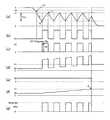
図4は、パルス充電装置160の各部の動作波形図であり、図4(a)は、増幅器143の出力電圧VCを平滑化した信号(比較器180の入力端子電圧)VEと基準電圧発生部153からの基準電圧VFの動作波形、図4(b)は、ANDゲート回路181の出力信号(充電時の比較器180の出力信号)VGの動作波形、図4(c)は、増幅器143の出力電圧VCの動作波形、図4(d)は、電流検出抵抗Rsの外部電源側の電圧VAの動作波形、図4(e)は、電池電圧検出部130の比較器132出力VKの動作波形、図4(f)は、電流検出抵抗Rsの電池側の電圧VB、図4(g)は、充電電流Ichgを示す。 FIG. 4 is an operation waveform diagram of each part of the
図4(a),(b)に示すように、充電が開始されたとき、コンデンサ171に電荷が蓄積されており、比較器180の入力端子電圧VEが基準電圧VFより高い状態であったとすると、充電時の比較器180の出力信号はローレベル、比較器180の出力信号を論理積出力するANDゲート回路181の出力信号VGもローレベルであるので、NMOSトランジスタ182及びPMOSトランジスタ191はオフとなり、充電電流Ichgは流れず、電流検出抵抗Rsの両端の電圧VAとVBは、VA=VBとなる。つまり、図4(c)に示すように、VC=0であるので、VEは平均化部152によって徐々に減少していく(図4a.参照)。 As shown in FIGS. 4A and 4B, when charging is started, charge is accumulated in the
VEの電圧が比較器180の出力信号VGが反転する電圧であるVF−Vhysまで減少すると(図4b.参照)、比較器180の出力信号VGがローレベルからハイレベルに反転するため、図4(g)に示すように、充電電流Ichgが流れる。すなわち、充電時の比較器180の出力信号VGがハイレベルになると、NMOSトランジスタ182はオンし、NMOSトランジスタ182のドレイン電位がローレベルとなってNMOSトランジスタ182のドレイン電位をゲートに受けるPMOSトランジスタ191がオンし、外部電源300から二次電池110に充電電流Ichgが流れる。このとき、充電電流Ichgは、図3で示したように出力電流の最大値で制限がかかるため、充電電流IchgはIchg_maxと等しくなる。 When the voltage of VE decreases to VF-Vhys, which is a voltage at which the output signal VG of the
充電電流Ichgが流れると、電流検出抵抗Rsの外部電源側の電圧VAの電圧は、電流検出抵抗Rsの抵抗値をRsとすると次式(1)で示される。 When the charging current Ichg flows, the voltage VA on the external power supply side of the current detection resistor Rs is expressed by the following equation (1), where Rs is the resistance value of the current detection resistor Rs.
VA=VB+Ichg×Rs …(1)
上記式(1)において、Ichg×RsをVHとおくと、増幅器143の出力電圧VCの電圧は次式(2)で示される。VA = VB + Ichg × Rs (1)
In the above equation (1), when Ichg × Rs is set to VH, the voltage of the output voltage VC of the
VC=VH …(2)
VHがVFより高い場合、VEは平均化部152によって徐々にVC(=VH)に近づくので、VEはVFと必ず交差し(図4c.参照)、その交差点で比較器180の出力VGがハイレベルからローレベルに反転する。すると、充電電流Ichgが流れないためVC=0となり、増幅器143の出力電圧VCを平滑化した信号VEは平均化部152によって徐々に減少していく。VC = VH (2)
When VH is higher than VF, VE gradually approaches VC (= VH) by the averaging
この動作を繰り返すことにより、増幅器143の出力電圧VCを平滑化した信号VEは、基準電圧VFと(VF−Vhys)との間を増減するようになる(図4(a)参照)。上記ヒステリシス幅Vhysは、ヒステリシス幅Vhysを有する比較器180によって与えられ、このヒステリシス幅Vhysによってパルスが発生する。なお、ヒステリシス幅Vhysを使用せずにパルスを発生する例については実施の形態2により後述する。いま、抵抗170の抵抗値をR、コンデンサ171の静電容量をCとすると、信号VEの増加はおよそ{VH−(VF−Vhys)}/(CR)の傾き、減少はおよそ−VF/(CR)の傾きとなる。したがって、充電電流Ichgの平均値Ichg_aveは、およそ次式(3)で表される。 By repeating this operation, the signal VE obtained by smoothing the output voltage VC of the
Ichg_ave=
VF×Ichg_max/(Rs×Ichg_max+Vhys) …(3)
ヒステリシス幅Vhysは通常、微小であるため、充電電流の平均値Ichg_aveは、およそ次式(4)のように表される。Ichg_ave =
VF × Ichg_max / (Rs × Ichg_max + Vhys) (3)
Since the hysteresis width Vhys is usually very small, the average value Ichg_ave of the charging current is approximately expressed by the following equation (4).
Ichg_ave=VF/Rs …(4)
このように、平均化部152の出力電圧VEが、基準電圧VFと(VF−Vhys)との間の増減することにより、図4(g)に示すパルス充電電流Ichgが流れ、二次電池110が充電される。二次電池110が充電されていくと、図4(f)に示すように電流検出抵抗Rsの充電電池110側の電圧VBの電圧レベルが上昇するとともに、図4(d)に示すように電流検出抵抗Rsの外部電源側の電圧VAの平均レベルも上昇する。電圧VBの電圧レベルが電池電圧検出部130の基準電圧発生部131の充電完了基準電圧VJに達すると(図4d.参照)、図4(e)に示すように比較器132の出力VKはハイレベルからローレベルに変わり、制御部151のANDゲート回路181の出力VGは、比較部154の出力レベルに関わらずローレベルとなる。これにより、NMOSトランジスタ182及びPMOSトランジスタ191はオフとなり、充電電流Ichgは流れず、二次電池110の充電が終了する。Ichg_ave = VF / Rs (4)
Thus, when the output voltage VE of the averaging
以上説明したように、本実施の形態によれば、パルス充電装置160は、外部電源300からの充電電流をオン/オフするスイッチ部120と、電流検出抵抗Rsによって充電電流Ichgを検出する電流検出部140と、電流検出部140の出力を平均化する平均化部152と、基準信号VFを発生する基準電圧発生部153と、平均化部152の出力電圧VEと基準信号VFとを比較する比較部154と、比較部154の出力に基づいてスイッチ部120を制御する制御部151とを備え、比較部154は、ヒステリシス幅Vhysを有する比較器180からなり、基準電圧VFとヒステリシス幅Vhysとの間で反転信号を出力し、制御部151は、比較器180からの反転信号に基づいてスイッチ部120をオン/オフ制御するので、充電電流Ichgが一定レベル範囲内に収まるようにパルス制御が行われ、充電電流Ichgの平均値Ichg_aveを目標の一定値に設定することができる。これにより、充電電流Ichgの平均値Ichg_aveが定電流化されたパルス充電電流を供給することができる。上記パルス制御は、充電電流Ichgを検出し、この検出情報を制御部151にフィードバックさせることで始めて実現できる。すなわち、従来例のように電池電圧を検出するだけでは、電池の充電状況は明確に把握できないため、平均充電電流を適正値に一致させるというような充電電流の細やかな制御は難しい。これに対して、本パルス充電制御では、充電途中にある二次電池110の電池電圧を、充電電流Ichgを検出することで電池の充電状況として把握することが可能になる。 As described above, according to the present embodiment,
また、基準電圧発生部153により発生させる基準電圧VFを、制御部151からの指示によって変更することも可能である。例えば、基準電圧VFを電池電圧Vbattに応じて調整するようにすれば、電池の充電状況に応じてより適切なパルス充電電流を供給することができる。また、本実施の形態にあっても、電池電圧検出部130が二次電池110の電池電圧VBを検出しており、パルス充電制御の充電完了条件として用いている。 In addition, the reference voltage VF generated by the
以上のように、平均充電電流Ichg_aveを、電池電圧に応じて細かに制御可能になるため、電池に対し過大な電流を流してしまい電池を劣化させてしまうといった不具合を防止することができる。また、より細かなパルス充電制御が可能になるため、充電時間の短縮が期待できる。また、ドロッパ方式の充電装置に比べ低発熱な充電ができる。 As described above, since the average charging current Ichg_ave can be finely controlled according to the battery voltage, it is possible to prevent a problem that an excessive current flows through the battery and the battery is deteriorated. In addition, since finer pulse charge control is possible, a reduction in charge time can be expected. Further, the battery can be charged with lower heat generation than a dropper charging device.
なお、本実施の形態では、基準電圧VFを図4に示すVHより低く設定したが、VFをVHより高く設定するようにすれば、信号VEは信号VFに到達せず、信号VGは常にハイレベルとなる。このことにより、スイッチ部120はオン状態に固定され、充電電流Ichgを常にIchg_maxとさせることも可能である。 In this embodiment, the reference voltage VF is set lower than VH shown in FIG. 4. However, if VF is set higher than VH, the signal VE does not reach the signal VF, and the signal VG is always high. Become a level. As a result, the
また、パルス充電電流Ichgの周波数は、平均化部152の抵抗170とコンデンサ171のCR時定数と、比較器180のヒステリシス幅Vhysによって、調整することができる。 The frequency of the pulse charging current Ichg can be adjusted by the CR time constant of the
(実施の形態2)
図5は、本発明の実施の形態2に係るパルス充電装置の構成を示すブロック図である。本実施の形態の説明に当たり、図1と同一部分には同一符号を付して重複箇所の説明を省略する。(Embodiment 2)
FIG. 5 is a block diagram showing the configuration of the pulse charging apparatus according to Embodiment 2 of the present invention. In the description of the present embodiment, the same parts as those in FIG.
図5において、400はパルス充電装置を含む電池パック、200は負荷回路201を備える携帯電話機などの携帯機器、300は充電用電源として充電電流Ichgを供給する能力を有するACアダプタである。ACアダプタ300から出力された直流電圧Vinが携帯機器200に供給されるとともに、電池パック400へ充電電流を供給する。 In FIG. 5, 400 is a battery pack including a pulse charging device, 200 is a portable device such as a mobile phone provided with a
電池パック400は、電池電圧V1,V2,V3を発生する3つのセルB1,B2,B3からなる二次電池110と、二次電池110に供給される充電電流をオン/オフするスイッチ部120と、二次電池110の各セルB1,B2,B3の電圧V1,V2,V3を足し合わせた二次電池110の電圧Vbattを検出する電池電圧検出部130と、二次電池110を充電する充電電流を検出する電流検出部140と、電池パック400全体のパルス充電制御及びスイッチ部120のオン/オフを制御するパルス充電制御部450とを備えて構成される。 The
上記スイッチ部120、電池電圧検出部130、電流検出部140、及びパルス充電制御部450は、パルス充電装置460を構成する。 The
パルス充電制御部450は、スイッチ部120のオン/オフを制御する制御部151と、基準電圧を発生する基準電圧発生部153と、電流検出部140により検出された信号を平均化し、基準電圧発生部153からの出力信号VFと比較する平均化部452と、
三角波信号VTを発生する三角波発生部453と、平均化部152からの信号VEと三角波発生部453からの三角波信号VTを比較する比較部454とを備えて構成される。なお、三角波発生部453により三角波信号VTを発生するが、三角波の名称は便宜的なものであり鋸歯状波を含む概念であることは言うまでもない。The pulse
A triangular
図6は、上記パルス充電装置460の詳細な構成を示す回路図である。図2と同一部分には同一符号を付して重複箇所の説明を省略する。 FIG. 6 is a circuit diagram showing a detailed configuration of the
図6において、パルス充電制御部450は、制御部151、基準電圧発生部153、平均化部452、三角波発生部453、及び比較部454から構成される。 In FIG. 6, the pulse
平均化部452は、差動増幅器470、抵抗471、及び帰還容量472からなる積分器を構成し、電流検出部140により検出された信号を平均化し、基準電圧発生部153からの基準電圧VFと比較して信号VEを出力する。 The averaging
比較部454は、比較器480からなり、比較器480は、平均化部452からの信号VEと三角波発生部453からの三角波信号VTとを比較し、制御部151のNMOSトランジスタ182を駆動する信号VGをANDゲート回路181に出力する。比較器480は、ヒステリシスを持たないコンパレータである。 The
以下、上述のように構成されたパルス充電装置の動作について説明する。 Hereinafter, the operation of the pulse charging apparatus configured as described above will be described.
図7は、パルス充電装置460の各部の動作波形図であり、図7(a)は、増幅器143の出力電圧VCを積分した信号(比較器480の入力端子電圧)VEと三角波信号VTの動作波形、図7(b)は、ANDゲート回路181の出力信号(充電時の比較器180の出力信号)VGの動作波形、図7(c)は、増幅器143の出力電圧VCの動作波形、図7(d)は、電流検出抵抗Rsの外部電源側の電圧VAの動作波形、図7(e)は、電池電圧検出部130の比較器132出力VKの動作波形、図7(f)は、電流検出抵抗Rsの電池側の電圧VB、図7(g)は、充電電流Ichgを示す。 FIG. 7 is an operation waveform diagram of each part of the
図7(a),(b)に示すように、充電が開始されたとき、コンデンサ171に電荷が蓄積されており、増幅器143の出力電圧VCを積分した信号VEが三角波信号VTより低い状態であったとすると、充電時の比較器480の出力信号はローレベル、比較器480の出力信号を論理積出力するANDゲート回路181の出力信号VGもローレベルであるので、NMOSトランジスタ182及びPMOSトランジスタ191はオフとなり、充電電流Ichgは流れず、電流検出抵抗Rsの両端の電圧VAとVBは、VA=VBとなる。つまり、図7(c)に示すように、VC=0であるので、VEは平均化部452によって徐々に増加していく(図7a.参照)。 As shown in FIGS. 7A and 7B, when charging is started, electric charge is accumulated in the
VEの電圧が三角波信号VTまで増加すると(図7b.参照)、比較器480の出力信号VGがローレベルからハイレベルに反転するため、図7(g)に示すように、充電電流Ichgが流れる。すなわち、充電時の比較器480の出力信号VGがハイレベルになると、NMOSトランジスタ182はオンし、NMOSトランジスタ182のドレイン電位がローレベルとなってNMOSトランジスタ182のドレイン電位をゲートに受けるPMOSトランジスタ191がオンし、外部電源300から二次電池110に充電電流Ichgが流れる。このとき、充電電流Ichgは、図3で示したように出力電流の最大値で制限がかかるため、充電電流IchgはIchg_maxと等しくなる。 When the voltage of VE increases to the triangular wave signal VT (see FIG. 7b), the output signal VG of the
充電電流Ichgが流れると、電流検出抵抗Rsの外部電源側の電圧VAの電圧は、電流検出抵抗Rsの抵抗値をRsとすると前記式(1)で示される。 When the charging current Ichg flows, the voltage VA on the external power supply side of the current detection resistor Rs is expressed by the above equation (1), where Rs is the resistance value of the current detection resistor Rs.
前記式(1)において、Ichg×RsをVHとおくと、増幅器143の出力電圧VCの電圧は前記式(2)で示される。 In the above equation (1), when Ichg × Rs is set to VH, the voltage of the output voltage VC of the
VHがVFより高い場合、VEは平均化部452によって徐々に減少するので、VEはVFと必ず交差し(図7c.参照)、その交差点で比較器480の出力VGがハイレベルからローレベルに反転する。すると、充電電流Ichgが流れないためVC=0となり、増幅器143の出力電圧VCを積分した信号VEは平均化部452によって徐々に増加していく。 When VH is higher than VF, VE is gradually reduced by the averaging
いま、抵抗170の抵抗値をR、コンデンサ171の静電容量をCとすると、信号VEの増加はVH/(CR)の傾き、減少は(VF−VF)/(CR)の傾きとなる。また、三角波信号VTが周期TでVT1とVT2(VT1>VT2)の間を等しい時間で増減するものとすると、充電電流の平均値Ichg_aveは、およそ次式(5)のように表される。 Now, assuming that the resistance value of the
Ichg_ave=VF/Rs …(5)
以上のように、基準電圧VFと検出抵抗Rsによって、充電電流の平均値Ichg_aveは一定値に設定できる。さらに、基準電圧VFは、制御部151によって電池電圧Vbattに応じて調整されるので、本実施の形態1のパルス充電装置は、電池の充電状況に応じて平均値が定電流化されたパルス充電電流を供給することができる。Ichg_ave = VF / Rs (5)
As described above, the average value Ichg_ave of the charging current can be set to a constant value by the reference voltage VF and the detection resistor Rs. Further, since the reference voltage VF is adjusted by the
このように、平均化部452の出力電圧VEと三角波信号VTとにより比較器480の出力信号VGが生成され、この増減パルス幅を持つ出力信号VGにより、図7(g)に示すパルス充電電流Ichgが流れ、二次電池110が充電される。二次電池110が充電されていくと、図7(f)に示すように電流検出抵抗Rsの充電電池110側の電圧VBの電圧レベルが上昇するとともに、図7(d)に示すように電流検出抵抗Rsの外部電源側の電圧VAの平均レベルも上昇する。電圧VBの電圧レベルが電池電圧検出部130の基準電圧発生部131の充電完了基準電圧VJに達すると(図7d.参照)、図7(e)に示すように比較器132の出力VKはハイレベルからローレベルに変わり、制御部151のANDゲート回路181の出力VGは、比較部454の出力レベルに関わらずローレベルとなる。これにより、NMOSトランジスタ182及びPMOSトランジスタ191はオフとなり、充電電流Ichgは流れず、二次電池110の充電が終了する。 As described above, the output signal VG of the
以上のように、本実施の形態によれば、充電電流Ichgの平均値Ichg_aveを目標の一定値に設定することができ、実施の形態1と同様な効果、すなわち、充電電流の細やかな制御により、電池に対し過大な電流を流してしまい電池を劣化させてしまうといった不具合を防止することができ、充電時間の短縮を図ることができる。 As described above, according to the present embodiment, the average value Ichg_ave of the charging current Ichg can be set to a target constant value, and the same effect as in the first embodiment, that is, by fine control of the charging current. In addition, it is possible to prevent a problem that an excessive current flows to the battery and deteriorates the battery, and it is possible to shorten the charging time.
なお、本実施の形態では、基準電圧VFを図7に示すVHより低く設定したが、基準電圧VFをVHより高く設定することにより、信号VEは増加を続け、やがて三角波信号VTより高くなる。このことにより、信号VGは常にハイレベルとなり、スイッチ部120はオン状態に固定され、充電電流を常にIchg_maxとさせることも可能である。 In this embodiment, the reference voltage VF is set lower than VH shown in FIG. 7, but by setting the reference voltage VF higher than VH, the signal VE continues to increase and eventually becomes higher than the triangular wave signal VT. Thus, the signal VG is always at the high level, the
また、パルス充電電流の周波数は、三角波信号VTの周波数と等しいことは自明であり、したがって制御部151によって三角波信号VTの周波数を調整することによって調整できる。図5には、図示していないが、実際には電池パック400内に充電時間を計時するタイマが設置されており、このタイマでは三角波信号VTを発生する三角波発生回路を備えている。したがって、三角波発生部453は、この三角波発生回路を用いることができ、部品点数の増大にはつながらない。 Further, it is obvious that the frequency of the pulse charging current is equal to the frequency of the triangular wave signal VT, and therefore can be adjusted by adjusting the frequency of the triangular wave signal VT by the
以上の説明は本発明の好適な実施の形態の例証であり、本発明の範囲はこれに限定されることはない。例えば、実施の形態は、電池パックの場合であるが、充電器の場合も同様の効果を得ることができる。 The above description is an illustration of a preferred embodiment of the present invention, and the scope of the present invention is not limited to this. For example, the embodiment is in the case of a battery pack, but the same effect can be obtained in the case of a charger.
また、上記各実施の形態ではパルス充電装置という名称を用いたが、これは説明の便宜上であり、充電装置、充電器、パルス充電方法等であってもよいことは勿論である。 In addition, although the name “pulse charging device” is used in each of the above embodiments, this is for convenience of explanation, and it is needless to say that the charging device, the charger, the pulse charging method, and the like may be used.
さらに、上記パルス充電装置を構成する各回路部、例えばスイッチ素子等の種類、数及び接続方法などは前述した実施の形態に限られない。スイッチ素子は、例えばMOSトランジスタを使用するのが一般的であるが、スイッチング動作を行う素子であればどのようなスイッチ素子であってもよい。 Furthermore, the type, number, connection method, and the like of each circuit unit that constitutes the pulse charging device, for example, the switch element, are not limited to the above-described embodiment. For example, a MOS transistor is generally used as the switch element, but any switch element may be used as long as the element performs a switching operation.
本発明に係るパルス充電装置は、携帯機器等の電池充電システムとして有用である。また、携帯機器以外の電子機器における充電器にも広く適用され得るものである。 The pulse charging device according to the present invention is useful as a battery charging system for portable devices and the like. Further, it can be widely applied to chargers in electronic devices other than portable devices.
100 電池パック
110 二次電池
120 スイッチ部
130 電池電圧検出部
131,153 基準電圧発生部
132,180,480 比較器
140 電流検出部
141,142 バッファ
143,470 差動増幅器
144〜147,170,471 抵抗
150,450 パルス充電制御部
151 制御部
152,452 平均化部
154,454 比較部
160,460 パルス充電装置
171 コンデンサ
181 ANDゲート回路
182 NMOSトランジスタ
183 プルアップ抵抗
191 PMOSトランジスタ
200 携帯機器
201 負荷回路
300 ACアダプタ(外部電源)
453 三角波発生部
472 帰還容量
Rs 電流検出抵抗DESCRIPTION OF
453
Claims (6)
Translated fromJapanese前記充電電流を検出する電流検出手段と、
前記電流検出手段の出力を平均化する平均化手段と、
基準信号を発生する基準信号発生手段と、
前記平均化手段の出力と前記基準信号とを比較する比較手段と、
前記比較手段の出力に基づいて前記スイッチ手段を制御する制御手段と
を備えることを特徴とするパルス充電装置。Switch means for turning on / off the charging current from the direct current source;
Current detecting means for detecting the charging current;
Averaging means for averaging the output of the current detection means;
A reference signal generating means for generating a reference signal;
Comparing means for comparing the output of the averaging means and the reference signal;
And a control means for controlling the switch means based on the output of the comparison means.
前記充電電流を検出する電流検出手段と、
前記電流検出手段の出力を平滑化する電圧平均化手段と、
三角波信号を発生する三角波発生手段と、
前記電圧平均化手段の出力と前記三角波信号とを比較する比較手段と、
前記比較手段の出力に基づいて前記スイッチ手段を制御する制御手段と
を備えることを特徴とするパルス充電装置。Switch means for turning on / off the charging current from the direct current source;
Current detecting means for detecting the charging current;
Voltage averaging means for smoothing the output of the current detection means;
A triangular wave generating means for generating a triangular wave signal;
Comparing means for comparing the output of the voltage averaging means with the triangular wave signal;
And a control means for controlling the switch means based on the output of the comparison means.
前記基準電圧と前記ヒステリシス幅との間で反転信号を出力し、
前記制御手段は、前記比較器からの前記反転信号に基づいて前記スイッチ手段をオン/オフ制御して、前記直流電流源からの充電電流を平均充電電流として定電流化することを特徴とする請求項1記載のパルス充電装置。The comparison means comprises a comparator having a hysteresis width,
An inverted signal is output between the reference voltage and the hysteresis width,
The control means performs on / off control of the switch means based on the inverted signal from the comparator, and constants the charging current from the DC current source as an average charging current. Item 1. A pulse charging device according to item 1.
前記制御手段は、前記比較器からの前記反転信号に基づいて前記スイッチ手段をオン/オフ制御して、前記直流電流源からの充電電流を平均充電電流として定電流化することを特徴とする請求項2記載のパルス充電装置。The comparison means compares the signal smoothed by the voltage averaging means with the triangular wave signal and outputs an inverted signal,
The control means performs on / off control of the switch means based on the inverted signal from the comparator, and constants the charging current from the DC current source as an average charging current. Item 3. The pulse charging device according to Item 2.
前記制御手段は、前記電池電圧検出手段により所定の電池電圧が検出されたとき、前記スイッチ手段をオフにする制御を行うことを特徴とする請求項1又は請求項2に記載のパルス充電装置。
Furthermore, the battery voltage detecting means for detecting the battery voltage of the secondary battery is provided,
3. The pulse charging device according to claim 1, wherein the control unit performs control to turn off the switch unit when a predetermined battery voltage is detected by the battery voltage detection unit.
Priority Applications (2)
| Application Number | Priority Date | Filing Date | Title |
|---|---|---|---|
| JP2006073445AJP2007252116A (en) | 2006-03-16 | 2006-03-16 | Pulse charger |
| US11/686,484US20070216359A1 (en) | 2006-03-16 | 2007-03-15 | Pulse charging apparatus |
Applications Claiming Priority (1)
| Application Number | Priority Date | Filing Date | Title |
|---|---|---|---|
| JP2006073445AJP2007252116A (en) | 2006-03-16 | 2006-03-16 | Pulse charger |
Publications (1)
| Publication Number | Publication Date |
|---|---|
| JP2007252116Atrue JP2007252116A (en) | 2007-09-27 |
Family
ID=38517108
Family Applications (1)
| Application Number | Title | Priority Date | Filing Date |
|---|---|---|---|
| JP2006073445AWithdrawnJP2007252116A (en) | 2006-03-16 | 2006-03-16 | Pulse charger |
Country Status (2)
| Country | Link |
|---|---|
| US (1) | US20070216359A1 (en) |
| JP (1) | JP2007252116A (en) |
Cited By (2)
| Publication number | Priority date | Publication date | Assignee | Title |
|---|---|---|---|---|
| JP2014236525A (en)* | 2013-05-30 | 2014-12-15 | 日本リライアンス株式会社 | Battery charge/discharge device, charge/discharge method, and program |
| JP2018121423A (en)* | 2017-01-24 | 2018-08-02 | 株式会社デンソーウェーブ | Charge / discharge device |
Families Citing this family (28)
| Publication number | Priority date | Publication date | Assignee | Title |
|---|---|---|---|---|
| JP2008148496A (en)* | 2006-12-12 | 2008-06-26 | Matsushita Electric Ind Co Ltd | Charger |
| JP2008182822A (en)* | 2007-01-24 | 2008-08-07 | Matsushita Electric Ind Co Ltd | Charger |
| JP2009284042A (en)* | 2008-05-20 | 2009-12-03 | Nec Electronics Corp | Pulse detection device, and pulse detection method |
| DE102009018098A1 (en)* | 2009-04-20 | 2010-10-21 | Austriamicrosystems Ag | Charging circuit for a charge storage and method for loading such |
| EP2355297B1 (en)* | 2010-02-06 | 2013-04-03 | Braun GmbH | Method for charging a battery, as well as a small, battery-operated electrical appliance and a charging circuit |
| US11397216B2 (en) | 2010-05-21 | 2022-07-26 | Qnovo Inc. | Battery adaptive charging using a battery model |
| US8791669B2 (en) | 2010-06-24 | 2014-07-29 | Qnovo Inc. | Method and circuitry to calculate the state of charge of a battery/cell |
| US10067198B2 (en) | 2010-05-21 | 2018-09-04 | Qnovo Inc. | Method and circuitry to adaptively charge a battery/cell using the state of health thereof |
| US11397215B2 (en) | 2010-05-21 | 2022-07-26 | Qnovo Inc. | Battery adaptive charging using battery physical phenomena |
| WO2011146783A1 (en) | 2010-05-21 | 2011-11-24 | Qnovo Inc. | Method and circuitry to adaptively charge a battery/cell |
| US11791647B2 (en) | 2010-05-21 | 2023-10-17 | Qnovo Inc. | Method and circuitry to adaptively charge a battery/cell |
| US8970178B2 (en) | 2010-06-24 | 2015-03-03 | Qnovo Inc. | Method and circuitry to calculate the state of charge of a battery/cell |
| US10389156B2 (en) | 2010-05-21 | 2019-08-20 | Qnovo Inc. | Method and circuitry to adaptively charge a battery/cell |
| US12081057B2 (en) | 2010-05-21 | 2024-09-03 | Qnovo Inc. | Method and circuitry to adaptively charge a battery/cell |
| US9142994B2 (en) | 2012-09-25 | 2015-09-22 | Qnovo, Inc. | Method and circuitry to adaptively charge a battery/cell |
| JP2012070476A (en)* | 2010-09-21 | 2012-04-05 | Panasonic Electric Works Co Ltd | Charging device |
| KR101332086B1 (en)* | 2012-05-31 | 2013-11-22 | 삼성전기주식회사 | System and method for supplying power |
| US9063018B1 (en) | 2012-10-22 | 2015-06-23 | Qnovo Inc. | Method and circuitry to determine temperature and/or state of health of a battery/cell |
| US9484770B2 (en) | 2012-12-07 | 2016-11-01 | Keme, Inc. | System and method of charging a chemical storage device |
| US9461492B1 (en) | 2013-04-19 | 2016-10-04 | Qnovo Inc. | Method and circuitry to adaptively charge a battery/cell using a charge-time parameter |
| CN103532201B (en)* | 2013-10-28 | 2015-06-24 | 无锡中星微电子有限公司 | Quick charge circuit for battery |
| US9553341B2 (en)* | 2014-02-25 | 2017-01-24 | Motorola Solutions, Inc. | Method and apparatus for controlling access to a logic circuit in a battery by multiple components connected to the battery |
| US10574079B1 (en) | 2014-06-20 | 2020-02-25 | Qnovo Inc. | Wireless charging techniques and circuitry for a battery |
| JP6477200B2 (en) | 2015-04-24 | 2019-03-06 | ミツミ電機株式会社 | Battery protection system, battery protection device, and battery protection method |
| EP3282550B1 (en)* | 2016-02-05 | 2020-04-15 | Guangdong Oppo Mobile Telecommunications Corp., Ltd. | Adapter and charging control method |
| US20240222721A1 (en)* | 2018-11-07 | 2024-07-04 | Qnovo Inc. | Battery adaptive charging using battery physical phenomena |
| US11243551B1 (en)* | 2020-09-24 | 2022-02-08 | Renesas Electronics America Inc. | Method and system of dynamic voltage compensation for electrical power delivery |
| SE2150806A1 (en)* | 2021-06-22 | 2022-12-23 | Ctek Sweden Ab | Method for communication between a battery charger and an electrically connected vehicle |
Family Cites Families (2)
| Publication number | Priority date | Publication date | Assignee | Title |
|---|---|---|---|---|
| US5289101A (en)* | 1990-04-27 | 1994-02-22 | Fuji Electric Co., Ltd. | Battery charger with charging current controller |
| US5523671A (en)* | 1991-02-14 | 1996-06-04 | Dell Usa, L.P. | Charging system for battery powered devices |
- 2006
- 2006-03-16JPJP2006073445Apatent/JP2007252116A/ennot_activeWithdrawn
- 2007
- 2007-03-15USUS11/686,484patent/US20070216359A1/ennot_activeAbandoned
Cited By (2)
| Publication number | Priority date | Publication date | Assignee | Title |
|---|---|---|---|---|
| JP2014236525A (en)* | 2013-05-30 | 2014-12-15 | 日本リライアンス株式会社 | Battery charge/discharge device, charge/discharge method, and program |
| JP2018121423A (en)* | 2017-01-24 | 2018-08-02 | 株式会社デンソーウェーブ | Charge / discharge device |
Also Published As
| Publication number | Publication date |
|---|---|
| US20070216359A1 (en) | 2007-09-20 |
Similar Documents
| Publication | Publication Date | Title |
|---|---|---|
| JP2007252116A (en) | Pulse charger | |
| US8035350B2 (en) | Battery charger | |
| JP3476347B2 (en) | Battery charger | |
| US7045990B2 (en) | Portable device having a charging circuit and semiconductor device for use in the charging circuit of the same | |
| US8222869B2 (en) | System and method for battery charging | |
| JP3584502B2 (en) | Charge control device | |
| US6320354B1 (en) | Method and apparatus for battery charging | |
| US7839122B2 (en) | Charging apparatus | |
| JP3823503B2 (en) | Secondary battery charging control method and charging device therefor | |
| WO2006108020A1 (en) | Energy storage apparatus and related method | |
| WO2005083868A1 (en) | Charger, dc/dc converter having that charger, and control circuit thereof | |
| JP3466029B2 (en) | Charger | |
| KR20160103391A (en) | Energy harvester and wireless switch using the same | |
| JP4152413B2 (en) | Charger and DC-DC converter provided with the charger | |
| TW202110029A (en) | Charge-pump control circuit and battery control circuit | |
| TWI259643B (en) | Capacitor charger to vary the charging current with the battery voltage, and method thereof | |
| US8723678B2 (en) | Device and method for detecting loading of battery | |
| US6906498B2 (en) | Device and method for the detection of a charging voltage | |
| US20090033291A1 (en) | Battery charger | |
| US6194868B1 (en) | Voltage indicator for indicating that the voltage of a battery passes a given value | |
| JP5313643B2 (en) | Battery diagnostic device | |
| JP3268513B2 (en) | Battery pack charger | |
| JPH10174298A (en) | Rechargeable DC power supply circuit | |
| JP2002345156A (en) | Rechargeable battery or rechargeable battery pack | |
| JP2003284334A (en) | Reference voltage generating circuit and battery charging circuit employing it |
Legal Events
| Date | Code | Title | Description |
|---|---|---|---|
| A621 | Written request for application examination | Free format text:JAPANESE INTERMEDIATE CODE: A621 Effective date:20081015 | |
| A761 | Written withdrawal of application | Free format text:JAPANESE INTERMEDIATE CODE: A761 Effective date:20090803 |