JP2007249364A - Safe driving support system and device - Google Patents
Safe driving support system and deviceDownload PDFInfo
- Publication number
- JP2007249364A JP2007249364AJP2006069175AJP2006069175AJP2007249364AJP 2007249364 AJP2007249364 AJP 2007249364AJP 2006069175 AJP2006069175 AJP 2006069175AJP 2006069175 AJP2006069175 AJP 2006069175AJP 2007249364 AJP2007249364 AJP 2007249364A
- Authority
- JP
- Japan
- Prior art keywords
- information
- driving support
- driver
- safe driving
- support system
- Prior art date
- Legal status (The legal status is an assumption and is not a legal conclusion. Google has not performed a legal analysis and makes no representation as to the accuracy of the status listed.)
- Pending
Links
Images


Classifications
- G—PHYSICS
- G02—OPTICS
- G02B—OPTICAL ELEMENTS, SYSTEMS OR APPARATUS
- G02B27/00—Optical systems or apparatus not provided for by any of the groups G02B1/00 - G02B26/00, G02B30/00
- G02B27/01—Head-up displays
- G—PHYSICS
- G02—OPTICS
- G02B—OPTICAL ELEMENTS, SYSTEMS OR APPARATUS
- G02B27/00—Optical systems or apparatus not provided for by any of the groups G02B1/00 - G02B26/00, G02B30/00
- G02B27/01—Head-up displays
- G02B27/0101—Head-up displays characterised by optical features
- G02B2027/0123—Head-up displays characterised by optical features comprising devices increasing the field of view
- G—PHYSICS
- G02—OPTICS
- G02B—OPTICAL ELEMENTS, SYSTEMS OR APPARATUS
- G02B27/00—Optical systems or apparatus not provided for by any of the groups G02B1/00 - G02B26/00, G02B30/00
- G02B27/01—Head-up displays
- G02B27/0101—Head-up displays characterised by optical features
- G02B2027/0138—Head-up displays characterised by optical features comprising image capture systems, e.g. camera
- G—PHYSICS
- G02—OPTICS
- G02B—OPTICAL ELEMENTS, SYSTEMS OR APPARATUS
- G02B27/00—Optical systems or apparatus not provided for by any of the groups G02B1/00 - G02B26/00, G02B30/00
- G02B27/01—Head-up displays
- G02B27/0101—Head-up displays characterised by optical features
- G02B2027/014—Head-up displays characterised by optical features comprising information/image processing systems
- G—PHYSICS
- G02—OPTICS
- G02B—OPTICAL ELEMENTS, SYSTEMS OR APPARATUS
- G02B27/00—Optical systems or apparatus not provided for by any of the groups G02B1/00 - G02B26/00, G02B30/00
- G02B27/01—Head-up displays
- G02B27/0179—Display position adjusting means not related to the information to be displayed
- G02B2027/0187—Display position adjusting means not related to the information to be displayed slaved to motion of at least a part of the body of the user, e.g. head, eye
Landscapes
- Physics & Mathematics (AREA)
- General Physics & Mathematics (AREA)
- Optics & Photonics (AREA)
- Traffic Control Systems (AREA)
Abstract
Description
Translated fromJapanese本発明は、車両のドライバが安全運転を行うことを支援するための情報を提供する安全運転支援システム、及びそのシステムに使用される安全運転支援装置に関する。 The present invention relates to a safe driving support system that provides information for assisting a driver of a vehicle to perform safe driving, and a safe driving support device used in the system.
特許文献1には、視点検出センサによって自車両のドライバの注視点を検出し、前方に存在する障害物について前方障害物センサにより自車両との位置関係が検出されているときは、その障害物が、検出された注視点を基準として設定した視野範囲内に相当する位置に存在するか否かに応じて、その障害物に関する情報提供の態様を変更するようにした車両用情報提供装置が開示されている。
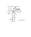
ところで、特許文献1では、ドライバに情報を提供するために、インストルメントパネル(インパネ)に配置された液晶表示器や、フロントガラスの下端部に映像を表示するHUD(ヘッドアップディスプレイ)などを用いている(図2参照)。しかしながら、インパネに配置された液晶表示器に情報を表示しても、車両を運転しているドライバの中心視野より外れた位置にあるため、ドライバが表示されている情報に気がつきにくいという問題がある。
一方、HUDはドライバの中心視野内に位置しているが、HUDに複雑な内容の情報を表示した場合には、ドライバがその内容を把握するために注意を払い、自車両周辺の状況確認が疎かになってしまうおそれがある。By the way, in
On the other hand, the HUD is located within the central visual field of the driver, but when the complicated information is displayed on the HUD, the driver pays attention to grasp the content and the situation around the vehicle is confirmed. There is a risk of being sneak.
そこで、特許文献1では、上記のような問題に対処するため、ドライバの注視点を検出し、前方に存在する障害物が、検出された注視点を基準とする視野範囲内に相当する位置に存在しない場合は情報の提供が必要であると判断して、障害物に関する情報の提供を行なうようにしている。
ところが、ドライバの死角に位置する障害物について情報提供を行うことを想定した場合には、特許文献1に開示されている技術は採用することができない。従って、ドライバにとって煩わしくない態様で、適切な情報提供を行うことができないという問題がある。Therefore, in
However, when it is assumed that information is provided for an obstacle located at the blind spot of the driver, the technique disclosed in
本発明は上記事情に鑑みてなされたものであり、その目的は、ドライバにとって煩わしくない態様で情報の提供を行うことができる安全運転支援システム、及びそのシステムに使用される安全運転支援装置を提供することにある。 The present invention has been made in view of the above circumstances, and an object thereof is to provide a safe driving support system capable of providing information in a manner that is not troublesome for a driver, and a safe driving support device used in the system. There is to do.
請求項1記載の安全運転支援システムによれば、車両に搭載される安全運転支援装置は、自車両の外部に設置されている情報送信手段によって送信される、ドライバにとって死角となる領域の情報を取得すると、制御手段は、取得した情報に基づき何れか1つの情報呈示手段により表示を行うことで運転支援情報を呈示させる。そして、その他の1つの情報呈示手段により、運転支援情報を表示している情報呈示手段を特定する補助情報の呈示を行う。
従って、車両のドライバは、補助情報が呈示された場合だけ運転支援情報を表示している情報呈示手段に視線を向ければ良いので、表示されている情報を確実に捉えることができる。また、補助情報として呈示される情報の量は比較的少なくても十分に用をなすので、補助情報の呈示自体がドライバに煩わしさを与えることはなく、車両の運転に悪影響を及ぼさずに運転支援情報を提供することができる。According to the safe driving support system of the first aspect, the safe driving support device mounted on the vehicle transmits the information on the area that is a blind spot for the driver, which is transmitted by the information transmitting means installed outside the host vehicle. Upon acquisition, the control means presents driving support information by performing display by any one of the information presenting means based on the acquired information. And the other one information presentation means presents the auxiliary information that identifies the information presentation means displaying the driving support information.
Therefore, since the driver of the vehicle has only to look at the information presenting means displaying the driving support information only when the auxiliary information is presented, the displayed information can be surely captured. In addition, since the amount of information presented as auxiliary information is sufficient even if it is relatively small, the presentation of auxiliary information itself does not bother the driver and drive without adversely affecting the driving of the vehicle. Support information can be provided.
請求項2記載の安全運転支援システムによれば、複数の情報呈示手段のうち運転支援情報を表示させるものを液晶表示器とし、補助情報を呈示させものをヘッドアップディスプレイ又は音声発生装置とする。即ち、車室内に配置される液晶表示器は比較的表示画面が大きく構成されるものが多いため、運転支援情報のように情報量が多いものを表示するのに適している。一方、ヘッドアップディスプレイは、表示領域が比較的小さいため情報量が少ないものを表示するのに適し、音声発生装置も短時間内で簡単なメッセージや警告音などを出力するのに適している。従って、これらにより補助情報を呈示するのが好適である。 According to the safe driving support system of the second aspect, the information display means that displays the driving support information is a liquid crystal display, and the auxiliary information that is displayed is a head-up display or a sound generator. That is, since many liquid crystal displays arranged in the passenger compartment have a relatively large display screen, they are suitable for displaying a large amount of information such as driving support information. On the other hand, the head-up display is suitable for displaying a small amount of information because the display area is relatively small, and the sound generating device is also suitable for outputting a simple message, warning sound, etc. within a short time. Therefore, it is preferable to present the auxiliary information by these.
請求項3記載の安全運転支援システムによれば、運転支援情報を表示させる液晶表示器を複数備えるので、外部より取得した情報の内容に応じて表示を行う液晶表示器を選択することで、例えば、運転支援情報をドライバに対してより直感的に把握させたり、或いは、情報の呈示をより効率的に行うことが可能となる。 According to the safe driving support system of the third aspect, since a plurality of liquid crystal displays that display driving support information are provided, by selecting a liquid crystal display that performs display according to the content of information acquired from the outside, for example, The driver assistance information can be grasped more intuitively by the driver, or the information can be presented more efficiently.
請求項4記載の安全運転支援システムによれば、制御手段は、視認状態検出手段によって運転支援情報を表示している情報呈示手段をドライバが視認したことが検出されると、補助情報の呈示を中止する。即ち、ドライバが表示された運転支援情報を認識すれば、それ以降に補助情報を呈示し続ける必要性はなくなるので、当該情報の呈示を中止することで煩わしさを軽減することができる。 According to the safe driving support system of the fourth aspect, when the driver detects that the information presenting means displaying the driving support information is visually recognized by the visual state detecting means, the control means presents the auxiliary information. Cancel. That is, if the driver recognizes the displayed driving support information, there is no need to continue presenting the auxiliary information after that, and the annoyance can be reduced by stopping the presentation of the information.
請求項5記載の安全運転支援システムによれば、視認状態検出手段は、視線方向判定手段により判定されたドライバの視線方向に応じて情報呈示手段をドライバが視認したことを検出するので、ドライバが運転支援情報を認識したか否かをより確実に判定することができる。 According to the safe driving support system of the fifth aspect, the visual state detection means detects that the driver visually recognizes the information presenting means according to the visual line direction of the driver determined by the visual line direction determination means. Whether or not the driving support information is recognized can be determined more reliably.
請求項6記載の安全運転支援システムによれば、車両が右ハンドル車であり、運転支援情報を表示する情報呈示手段がインストルメントパネルの中央部に配置されている場合、視認状態検出手段は、視線方向判定手段により判定されたドライバの視線方向が、左方向に20度以上から50度以下の範囲で、且つ下向に20度以上から50度以下の範囲にあれば、報呈示手段をドライバが視認したことを検出する。即ち、標準的な車室の内装状態を前提とすると、視線方向が上記の角度範囲内にあれば、ドライバはインストルメントパネル中央部付近に配置される情報呈示手段を視認することになるので、制御手段は妥当な判定を行うことができる。 According to the safe driving support system of the sixth aspect, when the vehicle is a right-hand drive vehicle and the information presenting means for displaying the driving support information is arranged at the center of the instrument panel, the visual state detecting means is If the driver's line-of-sight direction determined by the line-of-sight direction determining means is in the range from 20 degrees to 50 degrees in the left direction and in the range from 20 degrees to 50 degrees in the downward direction, the notification means is switched to the driver. Is detected. That is, assuming the standard interior condition of the passenger compartment, if the line-of-sight direction is within the above angle range, the driver will visually recognize the information presenting means arranged near the center of the instrument panel. The control means can make a reasonable decision.
請求項7記載の安全運転支援システムによれば、視認状態検出手段をドライバにより操作されるスイッチを備えて構成するので、ドライバ自らの意思によって、運転支援情報を認識したことを制御手段に確実に伝達することができる。 According to the safe driving support system of the seventh aspect, since the visual state detection means includes the switch operated by the driver, the control means reliably recognizes the driving support information according to the driver's own intention. Can communicate.
請求項8記載の安全運転支援システムによれば、視認状態検出手段を、ドライバによって発声される音声を認識する音声認識手段で構成するので、ドライバが運転支援情報を認識しタ場合は、例えば「見た」と発声することを定めておき、音声認識手段にその音声を認識すれば、請求項7と同様の効果を得ることができる。 According to the safe driving support system of the eighth aspect, since the visual state detection means is constituted by the voice recognition means for recognizing the voice uttered by the driver, when the driver recognizes the driving support information, for example, “ If it is determined that the voice is “seen” and the voice is recognized by the voice recognition means, the same effect as in the seventh aspect can be obtained.
請求項9記載の安全運転支援システムによれば、制御手段は、視認状態検出手段によって、ドライバが情報呈示手段を視認し続けている状態がある程度継続したことが検出されると、何れかの情報呈示手段によりドライバに対する警告メッセージを呈示するか、情報呈示手段による運転支援情報の表示を中止する。運転支援情報はあくまでも「運転を支援する」ための情報であり、最終的には、ドライバが自らの目によって周辺状況を確認する必要がある。そして、本発明のシステムに対する依存度が高くなり過ぎると、提供される情報のみに頼って運転を行ってしまうおそれもある。従って、ドライバが情報呈示手段に表示されている運転支援情報を視認し続けている場合には、警告を与えたり若しくは情報の表示を中止することにより、ドライバに対して目視による確認を促すことができる。 According to the safe driving support system of claim 9, the control means detects any information when the visual state detection means detects that the state in which the driver continues to visually recognize the information presentation means has continued to some extent. A warning message for the driver is presented by the presenting means, or the display of the driving support information by the information presenting means is stopped. The driving support information is information for “supporting driving” to the last, and finally, the driver needs to confirm the surrounding situation by his / her own eyes. And if the dependence on the system of the present invention becomes too high, there is a risk of driving depending on only the information provided. Therefore, when the driver continues to visually recognize the driving support information displayed on the information presenting means, the driver is prompted to confirm visually by giving a warning or canceling the display of information. it can.
請求項10記載の安全運転支援システムによれば、制御手段は、自車両が運転支援情報の呈示が最も有効であると推定される特定領域に位置する場合に請求項9の制御を行なう。即ち、本発明における「運転支援情報の呈示が最も有効な領域」とは、ドライバにとって死角が生じる可能性がある領域であり、車両の運転に一層の注意が要求される領域でもある。従って、車両がそのような領域に位置している場合、ドライバが運転支援情報を視認し続けると安全運転に支障を来たすおそれもある。そこで、車両が特定領域に位置する場合に請求項9の制御を行なえば、その制御に伴いドライバに対して与える警告も有効となる。 According to the safe driving support system of the tenth aspect, the control means performs the control of the ninth aspect when the host vehicle is located in a specific region where the presentation of the driving support information is estimated to be most effective. In other words, the “region where the presentation of driving support information is most effective” in the present invention is a region where a blind spot may occur for the driver, and is a region where further attention is required for driving the vehicle. Therefore, when the vehicle is located in such a region, if the driver continues to visually recognize the driving support information, there is a risk that safe driving may be hindered. Therefore, if the control of claim 9 is performed when the vehicle is located in the specific area, the warning given to the driver along with the control is also effective.
請求項11〜13記載の安全運転支援システムによれば、特定領域を、具体的には自車両が右折を行おうとする交差点の内部及びその手前30m以内に設定し(請求項11)、自車両から見てブラインドコーナーとなっている交差点の内部及びその手前50m以内に設定し(請求項12)、道路の本線に対する合流点の内部及びその手前100m以内に設定(請求項13)する。従って、夫々の運転ケースにおいて、特定領域を妥当に設定することができる。 According to the safe driving support system of
請求項14,15記載の安全運転支援システムによれば、警告メッセージの呈示は、表示(請求項14)又は音声の出力によって(請求項15)行うので、ドライバに対して視覚又は聴覚により警告を与えることができる。 According to the safe driving support system of claims 14 and 15, since the warning message is presented by display (claim 14) or by outputting sound (claim 15), the driver is visually or auditorily warned. Can be given.
(第1実施例)
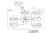
以下、本発明の第1実施例について図1乃至図6を参照して説明する。図1は、安全運転支援システムの構成を概略的に示す機能ブロック図である。安全運転支援装置1は車両に搭載されており、車両の走行中において路側等(例えば、交差点)に設置されている路上カメラ(情報送信手段)2により撮像され、無線信号として送信された映像情報を、情報受信装置3によって受信する。両者間の通信には、例えばDSRC(Dedicated Short Range Communication)通信)が使用される。(First embodiment)
Hereinafter, a first embodiment of the present invention will be described with reference to FIGS. FIG. 1 is a functional block diagram schematically showing the configuration of the safe driving support system. The safe
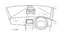
情報受信装置3によって受信された映像情報は、復調されて情報呈示制御装置(制御手段)4に出力される。情報呈示制御装置4は、液晶表示器(情報呈示手段)5,HUD(ヘッドアップディスプレイ,情報呈示手段)6による表示を制御すると共に、音声発生装置(スピーカ,情報呈示手段)7による音声信号の出力を制御する。ここで、図2に示すように、HUD6は、車両運転者の前方視野における上方領域(図2では二点鎖線で示す:以下、表示領域と呼ぶ)Aに映像を投影する構成となっている。また、液晶表示器5は、例えばカーナビゲーション装置(図示せず)に使用されているものを利用しても良く、車両のインストルメントパネル(インパネ)中央に配置されている。 The video information received by the
また、情報呈示制御装置4には、位置取得装置8により取得された車両の位置情報が与えられている。位置取得装置8は、例えば上述のカーナビゲーション装置において周知のGPS受信機などを含んで構成されるものである。尚、安全運転支援装置1と路上カメラ2とを加えたものが、安全運転支援システム10を構成している。 The information
次に、本実施例の作用について図3乃至図6も参照して説明する。図4は、安全運転支援システムの動作を説明するために、道路状況の一例を示す図(平面図)である。自車両11は、交差点内で右折待ちをしており、自車両11の前方では、対向車両12が右折待ちをしている。そのため、自車両11からは対向車両12によって視界が遮られており、自車両11のドライバは、前方より交差点に直進して来る対向車両13を直接目視できない状態にある。即ち、対向車両13は、自車両11のドライバにとって死角に位置している。そしてこの場合、路上カメラ2は、図2中右下に位置して交差点を俯瞰している。
また、図中に示す領域A,B,Cは、路上カメラ2からの映像情報を受信可能となる領域である。例えば、領域Bは交差点の内部及びその手前30m以内の領域に設定されており、領域Aは、領域Bの手前100m以内の領域、領域Cは、交差点を通過する車両が右折して領域Bを抜けた後に続く領域である。Next, the operation of this embodiment will be described with reference to FIGS. FIG. 4 is a diagram (plan view) illustrating an example of a road situation in order to explain the operation of the safe driving support system. The
In addition, areas A, B, and C shown in the figure are areas in which video information from the
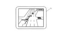
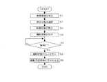
図3は、自車両11が領域Aに進入した場合に開始される、安全運転支援装置1の情報呈示制御装置4を中心とする処理内容を示すフローチャートである。情報呈示制御装置4は、路上カメラ2より送信される交差点の映像情報を受信すると(ステップS1)、その映像情報を液晶表示器5に表示させる(ステップS2)。図5には、液晶表示器5の画面における表示例を示す。 FIG. 3 is a flowchart showing processing contents centered on the information
そして、HUD6には、図6に示すように「支援情報表示中」の文字メッセージ(補助情報)を表示させて、ドライバに対して液晶表示器5に死角領域の映像、即ち、運転支援情報が表示されていることを呈示する。同時に、音声発生装置7により、例えば「支援情報表示中」などの音声メッセージや警告音など(補助情報)を出力させる(ステップS3)。これにより、自車両11のドライバは、前方を見ながら、インパネ中央の液晶表示器5に運転支援情報が表示されていることを知ることができる。尚、音声メッセージや警告音などの出力は1回だけでも良いし、運転支援情報が表示されている間は所定時間毎に出力を繰り返すようにしても良い。 As shown in FIG. 6, the
それから、情報呈示制御装置4は、位置取得装置8より位置情報を取得して、自車両11が領域A,Bを通過して、領域Cに進入したか否かを判断する(ステップS4)。領域Cに到達していない場合は(「NO」)運転支援情報の表示状態を継続し、領域Cに進入した場合は(「YES」)交差点の右折を完了したことになるので、HUD6並びに音声発生装置7によるメッセージの出力を停止させ(ステップS5)、続いて液晶表示器5による支援情報の表示も停止させる(ステップS6)。 Then, the information
以上のように本実施例によれば、車両11に搭載される安全運転支援装置1は、交差点付近の路上に設置されている路上カメラ2によって送信される、ドライバにとって死角となる領域の映像情報を取得すると、情報呈示制御装置4は、その映像情報を液晶表示器5に運転支援情報として表示させる。そして、HUD6には、液晶表示器5に運転支援情報が表示されていることを示す補助情報を表示させると共に、音声発生装置7には「支援情報表示中」などの音声メッセージを出力させるようにした。 As described above, according to the present embodiment, the safe
従って、車両のドライバは、HUD6又は音声発生装置7により補助情報が呈示された場合だけ、運転支援情報を表示している液晶表示器5に視線を向ければ良いので、運転支援情報を表示されている場合に確実に捉えることができる。また、補助情報として表示される情報の量は比較的少なくても十分に用をなすので、補助情報の表示自体がドライバに煩わしさを与えることはなく、車両の運転に悪影響を及ぼさずに運転支援情報を提供することができる。 Therefore, the driver of the vehicle only has to look at the
そして、車室内のインパネに配置されるような液晶表示器5は比較的表示画面が大きく構成されているものが多いため、運転支援情報のように情報量が多いものを表示するのに適している。一方、HUD6は表示領域が比較的小さいため情報量が少ないものを表示するのに適し、音声発生装置7も短時間内で簡単なメッセージや警告音などを出力するのに適している。従って、これらにより補助情報を表示するのが好適である。 Since many
(第2実施例)
図7乃至図11は本発明の第2実施例を示すものであり、第1実施例と同一部分には同一符号を付して説明を省略し、以下異なる部分についてのみ説明する。第2実施例の安全運転支援装置21は、図7に示すように、4つの液晶表示器(情報呈示手段)22a〜22dがインストルメントパネル23に並べて配置されていると共に、フロントガラス24には、ウインドウシールドディスプレイ(WSD,情報呈示手段)25,HUD(情報呈示手段)26が縦に並べて表示されるようになっている。そして、情報呈示制御装置4は、外部の路上カメラ2等により送信される映像情報に含まれている視点位置情報に基づいて、運転支援情報を表示させる液晶表示器22、若しくはディスプレイ25を決定するようになっている。(Second embodiment)
7 to 11 show a second embodiment of the present invention. The same parts as those of the first embodiment are denoted by the same reference numerals and the description thereof is omitted. Only different parts will be described below. As shown in FIG. 7, the safe
ここで、図10及び図11には、第1実施例の図4とは異なる道路状況と、各状況に応じて領域A,B,Cがどのように設定されるのかを例示するものである。図10は、所謂ブラインドコーナーに相当する状況であり、自車両11に対して、T字路に右方向から進入しようとする車両が死角に位置する。この場合、交差点の右下角に建物などが位置しているため、死角が形成されている。そして、領域BはT字路の内部及びその手前50m以内に設定されている。また、路上カメラ(情報送信手段)27,28は、T字路の左下側,右下側に夫々配置されており、T字路に対して右方向,左方向から進入しようとする車両の映像を捉えるようになっている。 Here, FIGS. 10 and 11 illustrate road conditions different from those in FIG. 4 of the first embodiment and how the areas A, B, and C are set according to each situation. . FIG. 10 shows a situation corresponding to a so-called blind corner. A vehicle that is about to enter the T-shaped road from the right direction with respect to the
一方、図11は例えば高速道路の合流点であり、加速車線を走行して本線に合流しようとする自車両11に対し、本線を走行して後方から合流点に接近する車両が死角に位置することになる。この場合、領域Bは、合流点部分及びその手前100m以内が相当する。そして、路上カメラ(情報送信手段)29は、領域Bの後方側より、領域B全体の映像を捉えるようにして配置されている。 On the other hand, FIG. 11 shows, for example, a junction of a highway, and a vehicle that travels along the main line and approaches the junction from the rear is located in a blind spot with respect to the
即ち、図4,図10,図11夫々の道路状況に対応して、路上カメラ2,27〜29が配置されている箇所は異なっている。そして、斯様な場合、各路上カメラによって送信される映像情報には、当該情報がどのような視点から撮像されたものであるかを示す視点位置情報を含むようにする。そして、安全運転支援装置1の情報呈示制御装置4は、上記映像情報を受信すると、当該情報に付随している視点位置情報に基づいて運転支援情報を表示させる対象を決定する。 That is, the locations where the on-
次に、第2実施例の作用について図8及び図9も参照して説明する。第1実施例の図3相当図である図9において、情報呈示制御装置4は、ステップS1において映像情報を取得すると、視点位置情報に基づき運転支援情報を表示させる対象を選択する(ステップS7)。そして、続くステップS2では、選択した表示対象に運転支援情報を表示させる。以降の処理は第1実施例と同様である。 Next, the operation of the second embodiment will be described with reference to FIGS. In FIG. 9 corresponding to FIG. 3 of the first embodiment, the information
例えば、図4に示すケースは自車両11が交差点を右折するシーンであり、視点位置情報に基づいて運転支援情報をWSD25に表示させる。すると、前方から交差点に進入しようとしている対向車両の映像が、対応する位置関係で表示されることになる。この時、HUD26には、図8に示すように例えば「支援情報表示中↑」といったような、上方のWSD25に運転支援情報が表示されていることを示すための補助情報を表示させる(ステップS3)。 For example, the case shown in FIG. 4 is a scene in which the
また、図10に示すケースは自車両11がT字路に進入しようとするシーンであり、両サイドの路上カメラ27,28により撮像された映像は、夫々液晶表示器22a,22dに表示される。従って、T字路に右方向,左方向から夫々進入しようとする車両の映像が、対応する位置関係で表示されることになる。
そして、図11に示すケースは自車両11が合流点に進入しようとするシーンであり、路上カメラ29により撮像された映像は、液晶表示器22dに表示される。従って、合流点に自車両11の右後方側より接近してくる後方車両の映像が、対応する位置関係で表示されることになる。The case shown in FIG. 10 is a scene in which the
The case shown in FIG. 11 is a scene in which the
また、液晶表示器22やディスプレイ25,26は運転支援情報だけを表示するものに限ることなく、車両11に例えばカーナビゲーション装置が搭載されている場合には、目的地までの案内経路に沿って道路案内情報を表示させても良いことは言うまでもない。従って、車両11の走行状態に応じて、各表示器の表示状態を適宜変更しても良い。
例えば、図4に示すケースにおいて、WSD25に既に道路案内情報が表示されている場合には、運転支援情報を液晶表示器22cに表示させても良い。また、図10に示すケースにおいて、例えば自車両11に、自車両11の左後方側領域の映像を撮像するカメラが搭載されており、その映像を液晶表示器22aに表示させている場合には、路上カメラ27の映像を液晶表示器22bに表示させても良い。
更に、図4に示すケースにおいて、自車両11が領域Aに位置する場合はWSD25に道路案内情報を表示させて、運転支援情報を液晶表示器22dに表示させる。そして、自車両11が領域Bに進入した場合は、上記の表示関係を逆にする。即ち、各情報の優先度に応じて表示状態をダイナミックに変更しても良い。In addition, the liquid crystal display 22 and the
For example, in the case shown in FIG. 4, when road guidance information is already displayed on the
Further, in the case shown in FIG. 4, when the
以上のように第2実施例によれば、運転支援情報を表示させる表示器として、液晶表示器22を複数備えると共にWSD25を備え、外部より取得した映像情報の内容に応じて表示を行う液晶表示器22,WSD25を選択することで、例えば、運転支援情報をドライバに対してより直感的に把握させたり、或いは、情報の呈示をより効率的に行うことが可能となる。 As described above, according to the second embodiment, the liquid crystal display that includes the plurality of liquid crystal displays 22 and the
(第3実施例)
図12乃至図14は本発明の第3実施例を示すものである。第3実施例の安全運転支援装置31は、図12に示すように、ドライバの瞳を中心とする顔面の画像を撮像するための視線検出カメラ(視認状態検出手段)32と、視線検出カメラ32により撮像された画像を処理することで、ドライバの視線方向を検出する視線方向判定装置(視認状態検出手段)33とを備えている。(Third embodiment)
12 to 14 show a third embodiment of the present invention. As shown in FIG. 12, the safe
視線方向判定装置33は、図13に示すように、ドライバの正面向きの視点を基準として、現在の視点が向いている方向を判定し、情報呈示制御装置(制御手段,視認状態検出手段)34に出力する。情報呈示制御装置34には、インパネに配置された液晶表示器5の幾何学的配置によって決まる視線方向が記憶されている。そして、情報呈示制御装置34は、視線方向判定装置33が判定したドライバの視線方向に基づき、ドライバの視線が液晶表示器5を捉えたか否かを判定可能となっている。
上記の判定は、車両の構造や内装、液晶表示器の画面の大きさ等によって異なるが、例えば車両が右ハンドルの場合は、左向き20度〜50度の範囲で、且つ下向き20度〜50度の範囲内にドライバの視線が位置した場合に液晶表示器5を捉えたと判定する。左ハンドルの場合は、前者が右向き20度〜50度の範囲となる。As shown in FIG. 13, the line-of-sight
The above determination differs depending on the structure and interior of the vehicle, the screen size of the liquid crystal display, and the like. For example, when the vehicle is a right steering wheel, the range is 20 degrees to 50 degrees leftward and 20 degrees to 50 degrees downward. It is determined that the
次に、第3実施例の作用について図14も参照して説明する。図14に示すフローチャートにおいて、情報呈示制御装置34は、ステップS1〜S3までは第1実施例と同様に処理を行ない、続くステップS11において、視線方向判定装置33が判定したドライバの視線方向が液晶表示器5を捉えたか否かを判定する(ステップS11)。そして、ドライバの視線が液晶表示器5を捉えていなければ(「NO」)ステップS4に移行し、(自車両11が領域Cに進入するまでは)ステップS2,S3で行った表示状態を継続する。一方、ステップS11においてドライバの視線が液晶表示器5を捉えた場合は(「YES」)その時点でHUD6における補助情報の表示を停止し(ステップS12)、ステップS4に移行する。その他の処理は第1実施例と同様である。 Next, the operation of the third embodiment will be described with reference to FIG. In the flowchart shown in FIG. 14, the information
以上のように第3実施例によれば、情報呈示制御装置34は、視線方向判定装置33により判定されたドライバの視線方向に応じて、運転支援情報を表示している液晶表示器5をドライバが視認したことを検出すると、HUD6に対する補助情報の表示を中止するので、補助情報を無意味に表示し続ける状態を回避して煩わしさを軽減することができる。そして、ドライバの視線方向に基づいて視認の有無を判定するので、ドライバが運転支援情報を認識したか否かをより確実に判定することができる。
また、情報呈示制御装置34は、右ハンドル車において、判定されたドライバの視線方向が、左方向に20度以上から50度以下の範囲で、且つ下向に20度以上から50度以下の範囲にあれば、液晶表示器5をドライバが視認したことを検出するので、視認の有無判定を妥当に判定行うことができる。As described above, according to the third embodiment, the information
Further, the information
(第4実施例)
図15及び図16は本発明の第4実施例を示すものであり、第3実施例と異なる部分について説明する。第4実施例の構成は基本的に第3実施例と同様であり、情報呈示制御装置34による処理内容が若干異なっている。ここで、第1実施例の図4に示すケースを参照して説明する。第4実施例では、ステップS11で(「NO」)と判断した場合、及びステップS12を実行した後は、自車両11が領域Bに位置しているか否かを判断する(ステップS13)。領域Bに位置していなければ(「NO」)ステップS4に移行する。(Fourth embodiment)
FIGS. 15 and 16 show a fourth embodiment of the present invention, and different parts from the third embodiment will be described. The configuration of the fourth embodiment is basically the same as that of the third embodiment, and the processing contents by the information
一方、ステップS13において自車両11が領域Bに位置している場合(「YES」)、情報呈示制御装置34は、ドライバの視線方向に基づいて、ドライバが液晶表示器5の表示を見過ぎていないかどうかを判断する(ステップS14)。ここで、領域Bは、図4,図10及び図11何れのケースにおいても、液晶表示器5に表示される運転支援情報が最も有効に活用されると想定される領域、即ちドライバにとって死角が生じる可能性がある領域であり、車両の運転に一層の注意が要求される領域でもある。 On the other hand, when the
従って、車両がそのような領域に位置している場合、ドライバが液晶表示器5の表示を視認し続けると安全運転に支障を来たすおそれもある。そこで、ステップS14では、ドライバの視線が液晶表示器5の方向に、例えば連続して1秒以上停留した場合に「見過ぎ」であると判断する。ステップS14において、ドライバが液晶表示器5を「見過ぎ」であると判断すると(「YES」)、情報呈示制御装置34は、HUD6の補助情報及び液晶表示器5の運転支援情報の表示を停止する(ステップS15,S16)。それから、ステップS4に移行する。 Therefore, when the vehicle is located in such a region, if the driver continues to visually recognize the display on the
ここで、ステップS15,S16を実行する替わりに、図16に示すように、液晶表示器5の画面に「注意! 道路状況を目視で確認して下さい」というような文字メッセージを表示させても良い。また、同様のメッセージを音声発生装置7より音声で出力しても良い。尚、図10に示すブラインドコーナーのケースや図11に示す合流のケースにおいても、ステップS13では同様に夫々のケースについて設定された領域Bを判断対象とすれば良い。即ち、安全に運転を行うには、自車両周辺の状況をドライバ自身が目視により確認することが大原則であるから、ドライバが運転支援情報を視認し続けている場合には警告を与えることが好ましい。 Here, instead of executing steps S15 and S16, as shown in FIG. 16, a text message such as “Caution! Check the road conditions visually” may be displayed on the screen of the
以上のように第4実施例によれば、情報呈示制御装置34は、図4,図10,図11の各ケースにおいて、自車両11が領域Bに位置する場合に第3実施例の制御を行なうので、夫々の運転ケースにつき妥当に設定した特定領域内で、ドライバに対して有効な警告を与えることができる。また、ドライバが液晶表示器5を「見過ぎ」であると判断した場合の警告メッセージを、液晶表示器5に文字メッセージを表示させたり、音声発生装置7より音声の出力によっても行うので、ドライバに対して視覚又は聴覚により警告を与えることができる。ドライバに対して目視による確認を積極的に促すことができる。 As described above, according to the fourth embodiment, the information
(第5,第6実施例)
図17,図18は本発明の第5,第6実施例であり、第3実施例と異なる部分について説明する。図17に示す第5実施例の安全運転支援装置41は、第3実施例の安全運転支援装置31より視線検出カメラ32及び視線方向判定装置33を削除し、替わりに視認スイッチ(視認状態検出手段)42を設けている。視認スイッチ42は、例えばハンドルに配置したプッシュスイッチなどで構成され、ドライバが液晶表示器5に表示された運転支援情報を見た場合に、視認スイッチ42を操作する。それにより、情報呈示制御装置34は、図14におけるステップS11で「YES」と判断する。(Fifth and sixth embodiments)
FIGS. 17 and 18 show fifth and sixth embodiments of the present invention, and different portions from the third embodiment will be described. The safe
また、図18に示す第6実施例の安全運転支援装置43は、音声認識装置(視認状態検出手段,音声認識手段)44を設けている。そして、ドライバは、液晶表示器5に表示された運転支援情報を見た場合は例えば「見た」と発生するように定めておく。すると、音声認識装置44は、その音声を認識して情報呈示制御装置34に認識結果を出力し、情報呈示制御装置34は、図14におけるステップS11で「YES」と判断する。
以上のように第5実施例によれば、視認状態検出手段を視認スイッチ42で構成し、また、第6実施例によれば、視認状態検出手段を音声を認識する音声認識装置44で構成するので、ドライバ自らの意思によって、運転支援情報を認識したことを情報呈示制御装置34に確実に伝達することができる。Further, the safe
As described above, according to the fifth embodiment, the visual state detection means is configured by the
本発明は上記し又は図面に記載した実施例にのみ限定されるものではなく、以下のような変形が可能である。
路側に設置されるカメラに限ることなく、自車両以外の車両に設置したカメラにより撮像された映像情報を受信しても良い。
運転支援情報は、必ずしもカメラにより撮像された映像に限ることなく、前記映像に基づき作成されたアニメーション画像や、映像の情報量を削減して概略化したり一部を強調するなどの加工した画像を表示しても良い。また、ドライバが直接目視できない信号機の状況や渋滞の情報を文字や記号で表示しても良い。
領域A,Bをどのような範囲で設定するかは、適宜変更すれば良い。
また、運転シーンについては、図4,図10,図11に示すものに限ることはない。
補助情報の提示は、HUD6,音声発生装置7の何れか一方のみによって行っても良い。The present invention is not limited to the embodiments described above or shown in the drawings, and the following modifications are possible.
The video information captured by a camera installed in a vehicle other than the host vehicle may be received without being limited to the camera installed on the roadside.
The driving support information is not necessarily limited to the video imaged by the camera, but is an animation image created based on the video image or a processed image that is simplified or emphasized by reducing the information amount of the video image. You may display. In addition, the traffic signal status and traffic information that cannot be directly seen by the driver may be displayed as characters or symbols.
The range in which the areas A and B are set may be changed as appropriate.
Further, the driving scene is not limited to those shown in FIGS. 4, 10, and 11.
The presentation of the auxiliary information may be performed by only one of the
第2実施例における液晶表示器22の数は1個以上あれば良い。また、液晶表示器22が2個以上ある場合はWSD25を削除しても良い。
第3実施例において、ドライバの視線が液晶表示器5を捉えたか否かの判定までを視線方向判定装置33で行い、情報呈示制御装置34には、その判定結果を出力するようにしても良い。
情報呈示手段において表示を行うものは、液晶表示器やHUD等に限ることなく、例えばEL(Electro-Luminescence)パネルなどでも良い。
情報送信手段は、路側に設置されるものに限ることなく、自車両以外の他の車両に設置されていても良い。
位置取得装置8は、例えばVICSのビーコン等により送信される位置情報を受信して取得するものでも良い。また、路上カメラより送信される情報に位置情報が含まれている場合は、設ける必要はない。The number of liquid crystal displays 22 in the second embodiment may be one or more. Further, when there are two or more liquid crystal displays 22, the
In the third embodiment, the line-of-sight
What is displayed in the information presenting means is not limited to a liquid crystal display or HUD, but may be an EL (Electro-Luminescence) panel, for example.
The information transmission means is not limited to the one installed on the road side, and may be installed in a vehicle other than the own vehicle.
The
ドライバが運転支援情報を視認したか否かの判断は、例えば以下のように行なっても良い。
・ドライバのシートに圧力検知センサを埋め込んでおき、運転支援情報が表示されている表示器をドライバが見ようとした場合に生じる、ドライバの姿勢や体勢の変化を圧力の変化に基づき判定する。
・ドライバの脳波を計測するセンサを備えて、脳波の変化に基づき判定する。
・アクセルやブレーキ,ハンドルの操作状態の変化に基づき判定する。
情報送信手段は、映像情報を送信するカメラに限ることはない。例えば、路側や他車両にレーザ,電波,超音波などを用いたセンサを設置し、自車両に対して死角領域に存在する注意対象車両の位置を検出し、その情報を送信するものでも良い。そして、自車両の安全運転支援装置側では、受信した情報に基づき地図画面上に注意対象車両の位置を合成して運転支援情報を表示すれば良い。The determination as to whether or not the driver visually recognizes the driving assistance information may be performed as follows, for example.
A pressure detection sensor is embedded in the driver's seat, and changes in the driver's posture and posture that occur when the driver tries to see a display on which driving support information is displayed are determined based on the change in pressure.
・ Equipped with a sensor that measures the brain waves of the driver, and makes a judgment based on changes in brain waves.
・ Determine based on changes in operating conditions of accelerator, brake and steering wheel.
The information transmission means is not limited to a camera that transmits video information. For example, a sensor using laser, radio waves, ultrasonic waves, or the like may be installed on the roadside or other vehicles to detect the position of the vehicle to be watched in the blind spot area relative to the own vehicle and transmit the information. And the safe driving assistance apparatus side of the own vehicle should just synthesize | combine the position of the attention object vehicle on a map screen based on the received information, and should display driving assistance information.
図面中、1は安全運転支援装置、2は路上カメラ(情報送信手段)、4は情報呈示制御装置(制御手段)、5は液晶表示器(情報呈示手段)、6はヘッドアップディスプレイ(情報呈示手段)、7は音声発生装置(情報呈示手段)、10は安全運転支援システム、11は自車両、21は安全運転支援装置、22は液晶表示器(情報呈示手段)、25ウインドウシールドディスプレイ(情報呈示手段)、26はヘッドアップディスプレイ(情報呈示手段)、27,28は路上カメラ(情報送信手段)、29は路上カメラ(情報送信手段)、31は安全運転支援装置、32は視線検出カメラ(視認状態検出手段)、33は視線方向判定装置(視認状態検出手段)、34は情報呈示制御装置(制御手段,視認状態検出手段)、41は安全運転支援装置、42は視認スイッチ(視認状態検出手段)、43は安全運転支援装置、44は音声認識装置(視認状態検出手段,音声認識手段)を示す。 In the drawings, 1 is a safe driving support device, 2 is a road camera (information transmission means), 4 is an information presentation control device (control means), 5 is a liquid crystal display (information presentation means), and 6 is a head-up display (information presentation). Means), 7 is a sound generating device (information presenting means), 10 is a safe driving support system, 11 is the own vehicle, 21 is a safe driving support device, 22 is a liquid crystal display (information presenting means), 25 window shield display (information (Presentation means), 26 is a head-up display (information presentation means), 27 and 28 are road cameras (information transmission means), 29 is a road camera (information transmission means), 31 is a safe driving support device, and 32 is a gaze detection camera ( (Visual state detection means), 33 is a gaze direction determination device (visual state detection means), 34 is an information presentation control device (control means, visual state detection means), and 41 is a safe driving support device. , 42 viewing switch (observation state detection unit), 43 the safety driving support apparatus, 44 denotes a voice recognition device (observation state detection unit, the speech recognition means).
Claims (16)
Translated fromJapanese前記車両のドライバに情報を呈示するための複数の情報呈示手段と、
前記情報送信手段より取得した情報を、前記複数のうち何れか1つの情報呈示手段に表示させることで運転支援情報を呈示させると共に、その他の1つの情報呈示手段によって、前記運転支援情報を表示している情報呈示手段を特定する補助情報の呈示を行うように制御する制御手段とを備える安全運転支援装置とで構成されることを特徴とする安全運転支援システム。Information transmitting means installed outside the host vehicle and transmitting information on a region that may become a blind spot for the driver of the vehicle;
A plurality of information presenting means for presenting information to the driver of the vehicle;
The information acquired from the information transmitting means is displayed on any one of the plurality of information presenting means to display the driving support information, and the other one information presenting means displays the driving support information. A safe driving support system, comprising: a safe driving support device including control means for performing control so as to present auxiliary information for identifying the presenting information presenting means.
前記制御手段は、前記視認状態検出手段が前記情報呈示手段を前記ドライバが視認したことを検出すると、前記補助情報の呈示を中止することを特徴とする請求項1乃至3の何れかに記載の安全運転支援システム。A visual state detection means for detecting whether the driver of the vehicle visually recognizes the information presenting means displaying the driving support information;
The said control means stops the presentation of the said auxiliary information, if the said visual recognition state detection means detects that the said driver | operator visually recognized the said information presentation means. Safe driving support system.
ドライバの瞳を中心とする画像を撮像するための撮像手段と、
この撮像手段によって撮像された映像に基づいて前記ドライバの視線方向を判定する視線方向判定手段とで構成され、
前記視線方向判定手段により判定された前記ドライバの視線方向に応じて、前記情報呈示手段を前記ドライバが視認したことを検出することを特徴とする請求項4記載の安全運転支援システム。The visual state detection means includes
Imaging means for capturing an image centered on the driver's pupil;
A line-of-sight direction determining unit that determines a line-of-sight direction of the driver based on an image captured by the imaging unit;
5. The safe driving support system according to claim 4, wherein it is detected that the driver visually recognizes the information presenting unit according to the line-of-sight direction of the driver determined by the line-of-sight direction determining unit.
前記視認状態検出手段は、前記視線方向判定手段により判定された前記ドライバの視線方向が、ドライバが視線を正面に向けた状態を基準として、左方向に20度以上から50度以下の範囲で、且つ下向に20度以上から50度以下の範囲にある場合に、前記情報呈示手段を前記ドライバが視認したことを検出することを特徴とする請求項5記載の安全運転支援システム。When the vehicle is a right-hand drive vehicle and the information presenting means is installed at the center of the instrument panel in the passenger compartment,
The visual state detection means has a line-of-sight direction of the driver determined by the line-of-sight direction determination means in a range from 20 degrees to 50 degrees in the left direction with reference to a state where the driver faces the line of sight. 6. The safe driving support system according to claim 5, further comprising detecting that the driver visually recognizes the information presenting means when it is in a range of 20 degrees to 50 degrees downward.
前記制御手段は、自車両が前記運転支援情報の呈示が最も有効であると推定される特定領域に位置する場合に前記制御を行なうことを特徴とする請求項9記載の安全運転支援システム。A position acquisition means for acquiring the position of the host vehicle;
10. The safe driving support system according to claim 9, wherein the control means performs the control when the own vehicle is located in a specific region where the presentation of the driving support information is estimated to be most effective.
Priority Applications (3)
| Application Number | Priority Date | Filing Date | Title |
|---|---|---|---|
| JP2006069175AJP2007249364A (en) | 2006-03-14 | 2006-03-14 | Safe driving support system and device |
| US11/714,522US7680592B2 (en) | 2006-03-14 | 2007-03-06 | System and apparatus for drive assistance |
| DE102007011122ADE102007011122A1 (en) | 2006-03-14 | 2007-03-07 | System and device for driving assistance |
Applications Claiming Priority (1)
| Application Number | Priority Date | Filing Date | Title |
|---|---|---|---|
| JP2006069175AJP2007249364A (en) | 2006-03-14 | 2006-03-14 | Safe driving support system and device |
Publications (1)
| Publication Number | Publication Date |
|---|---|
| JP2007249364Atrue JP2007249364A (en) | 2007-09-27 |
Family
ID=38375126
Family Applications (1)
| Application Number | Title | Priority Date | Filing Date |
|---|---|---|---|
| JP2006069175APendingJP2007249364A (en) | 2006-03-14 | 2006-03-14 | Safe driving support system and device |
Country Status (3)
| Country | Link |
|---|---|
| US (1) | US7680592B2 (en) |
| JP (1) | JP2007249364A (en) |
| DE (1) | DE102007011122A1 (en) |
Cited By (7)
| Publication number | Priority date | Publication date | Assignee | Title |
|---|---|---|---|---|
| JP2010267211A (en)* | 2009-05-18 | 2010-11-25 | Toyota Motor Corp | Vehicle environment estimation device |
| JP2013092509A (en)* | 2011-10-27 | 2013-05-16 | Mazda Motor Corp | Visual guidance device for vehicle |
| JP2015232859A (en)* | 2014-06-11 | 2015-12-24 | 株式会社デンソー | Safety confirmation support system and safety confirmation support method |
| JP2018084860A (en)* | 2016-11-21 | 2018-05-31 | パナソニック インテレクチュアル プロパティ コーポレーション オブ アメリカPanasonic Intellectual Property Corporation of America | Intersection information distribution apparatus and intersection information distribution method |
| WO2018163266A1 (en)* | 2017-03-07 | 2018-09-13 | 三菱電機株式会社 | Display control device and display control method |
| JP2020144081A (en)* | 2019-03-08 | 2020-09-10 | 本田技研工業株式会社 | Agent device, control method of agent device, and program |
| CN114999225A (en)* | 2022-05-13 | 2022-09-02 | 海信集团控股股份有限公司 | Information display method for road object and vehicle |
Families Citing this family (31)
| Publication number | Priority date | Publication date | Assignee | Title |
|---|---|---|---|---|
| JP4848893B2 (en)* | 2006-08-29 | 2011-12-28 | 株式会社デンソー | Intersection information providing system and driving support system |
| KR100836677B1 (en)* | 2006-09-19 | 2008-06-10 | 주식회사 레인콤 | Automotive Navigation System with Auxiliary Display |
| JP4984974B2 (en) | 2007-03-02 | 2012-07-25 | 富士通株式会社 | Driving support system and in-vehicle device |
| KR100910114B1 (en)* | 2007-07-09 | 2009-08-03 | 팅크웨어(주) | Navigation system and speed limit information guide for each section |
| CN101451848B (en)* | 2007-12-07 | 2012-03-14 | 深圳富泰宏精密工业有限公司 | Vehicle carried pilot system |
| DE102008042521A1 (en) | 2008-10-01 | 2010-04-08 | Robert Bosch Gmbh | Procedure for displaying a visual warning |
| US20100082564A1 (en)* | 2008-10-01 | 2010-04-01 | Navteq North America, Llc | Spatial Index for Locating Geographic Data Parcels Stored on Physical Storage Media |
| US8762046B2 (en) | 2008-10-01 | 2014-06-24 | Navteq B.V. | Creating geometry for advanced driver assistance systems |
| US8725474B2 (en) | 2008-10-01 | 2014-05-13 | Navteq B.V. | Bezier curves for advanced driver assistance system applications |
| US8416300B2 (en)* | 2009-05-20 | 2013-04-09 | International Business Machines Corporation | Traffic system for enhancing driver visibility |
| US8878660B2 (en) | 2011-06-28 | 2014-11-04 | Nissan North America, Inc. | Vehicle meter cluster |
| JP5679449B2 (en) | 2011-07-08 | 2015-03-04 | アルパイン株式会社 | In-vehicle system |
| DE102011082617A1 (en)* | 2011-09-13 | 2013-03-14 | Continental Automotive Gmbh | Display and operating system for a motor vehicle |
| DE102011084915B4 (en)* | 2011-10-20 | 2021-01-21 | Continental Automotive Gmbh | Method for supporting a driver by means of a driver support device |
| US20130169785A1 (en)* | 2011-12-30 | 2013-07-04 | Agco Corporation | Method of detecting and improving operator situational awareness on agricultural machines |
| KR101449210B1 (en)* | 2012-12-27 | 2014-10-08 | 현대자동차주식회사 | Apparatus for converting driving mode of autonomous vehicle and method thereof |
| US9122933B2 (en)* | 2013-03-13 | 2015-09-01 | Mighty Carma, Inc. | After market driving assistance system |
| US9514650B2 (en) | 2013-03-13 | 2016-12-06 | Honda Motor Co., Ltd. | System and method for warning a driver of pedestrians and other obstacles when turning |
| US9047703B2 (en) | 2013-03-13 | 2015-06-02 | Honda Motor Co., Ltd. | Augmented reality heads up display (HUD) for left turn safety cues |
| US9580014B2 (en)* | 2013-08-08 | 2017-02-28 | Convoy Technologies Llc | System, apparatus, and method of detecting and displaying obstacles and data associated with the obstacles |
| DE102014114329A1 (en)* | 2014-10-02 | 2016-04-07 | Connaught Electronics Ltd. | Camera system for an electronic rearview mirror of a motor vehicle |
| US9588340B2 (en) | 2015-03-03 | 2017-03-07 | Honda Motor Co., Ltd. | Pedestrian intersection alert system and method thereof |
| CN105882524A (en)* | 2016-03-28 | 2016-08-24 | 乐视控股(北京)有限公司 | Control method and device of driving assistance system |
| US20170359519A1 (en)* | 2016-06-08 | 2017-12-14 | General Motors Llc | Vehicle information system and method |
| US20180136462A1 (en)* | 2016-11-15 | 2018-05-17 | E-Lead Electronic Co., Ltd. | Rotating head-up display device |
| DE102017111468A1 (en) | 2017-05-24 | 2018-11-29 | Automotive Safety Technologies Gmbh | A vehicle system and method for determining whether a vehicle occupant has sensed an off-vehicle object |
| EP3827297A4 (en)* | 2018-07-26 | 2022-01-26 | Bayerische Motoren Werke Aktiengesellschaft | Apparatus and method for use with vehicle |
| JP7087919B2 (en)* | 2018-10-31 | 2022-06-21 | トヨタ自動車株式会社 | Driving Assistance Equipment, Vehicles, Driving Assistance Methods and Programs |
| JP7357284B2 (en)* | 2020-02-12 | 2023-10-06 | パナソニックIpマネジメント株式会社 | Drawing system, display system, moving object, drawing method and program |
| JP2024105002A (en)* | 2023-01-25 | 2024-08-06 | トヨタ自動車株式会社 | Display control device and display control system |
| DE102023124502A1 (en)* | 2023-09-12 | 2025-03-13 | Dr. Ing. H.C. F. Porsche Aktiengesellschaft | Procedure for increasing traffic safety at a side junction |
Citations (4)
| Publication number | Priority date | Publication date | Assignee | Title |
|---|---|---|---|---|
| JPH07117593A (en)* | 1993-10-21 | 1995-05-09 | Mitsubishi Electric Corp | Vehicle alarm system |
| JP2000259818A (en)* | 1999-03-09 | 2000-09-22 | Toshiba Corp | Status information providing apparatus and method |
| JP2004249836A (en)* | 2003-02-20 | 2004-09-09 | Denso Corp | Display control system for vehicle |
| JP2005011252A (en)* | 2003-06-20 | 2005-01-13 | Mazda Motor Corp | Information providing device for vehicle |
Family Cites Families (8)
| Publication number | Priority date | Publication date | Assignee | Title |
|---|---|---|---|---|
| JPH04184481A (en) | 1990-11-20 | 1992-07-01 | Nissan Motor Co Ltd | Display device for vehicle |
| JP2001018717A (en) | 1999-07-06 | 2001-01-23 | Matsushita Electric Ind Co Ltd | Driving vehicle periphery monitoring device |
| JP4385392B2 (en) | 2000-06-15 | 2009-12-16 | マツダ株式会社 | Vehicle information providing device |
| DE20106977U1 (en)* | 2001-04-23 | 2002-08-29 | Mekra Lang Gmbh & Co Kg | Warning device in motor vehicles |
| DE10131720B4 (en)* | 2001-06-30 | 2017-02-23 | Robert Bosch Gmbh | Head-Up Display System and Procedures |
| US7209051B2 (en)* | 2002-03-05 | 2007-04-24 | University Of Minnesota | Intersection assistance system and method |
| DE102004035856A1 (en) | 2003-08-14 | 2005-03-10 | Roland Bittner | Electrical auxiliary device for use in a traffic system, e.g. a traffic data collection system or traffic warning system, whereby the device is mounted at least partially in a mounting tube or pipe of existing infrastructure |
| JP4683192B2 (en) | 2005-02-15 | 2011-05-11 | 株式会社デンソー | Vehicle blind spot monitoring device and vehicle driving support system |
- 2006
- 2006-03-14JPJP2006069175Apatent/JP2007249364A/enactivePending
- 2007
- 2007-03-06USUS11/714,522patent/US7680592B2/enactiveActive
- 2007-03-07DEDE102007011122Apatent/DE102007011122A1/ennot_activeCeased
Patent Citations (4)
| Publication number | Priority date | Publication date | Assignee | Title |
|---|---|---|---|---|
| JPH07117593A (en)* | 1993-10-21 | 1995-05-09 | Mitsubishi Electric Corp | Vehicle alarm system |
| JP2000259818A (en)* | 1999-03-09 | 2000-09-22 | Toshiba Corp | Status information providing apparatus and method |
| JP2004249836A (en)* | 2003-02-20 | 2004-09-09 | Denso Corp | Display control system for vehicle |
| JP2005011252A (en)* | 2003-06-20 | 2005-01-13 | Mazda Motor Corp | Information providing device for vehicle |
Cited By (15)
| Publication number | Priority date | Publication date | Assignee | Title |
|---|---|---|---|---|
| US11568746B2 (en) | 2009-05-18 | 2023-01-31 | Toyota Jidosha Kabushiki Kaisha | Vehicular environment estimation device |
| US11941985B2 (en) | 2009-05-18 | 2024-03-26 | Toyota Jidosha Kabushiki Kaisha | Vehicular environment estimation device |
| US9501932B2 (en) | 2009-05-18 | 2016-11-22 | Toyota Jidosha Kabushiki Kaisha | Vehicular environment estimation device |
| US12142146B2 (en) | 2009-05-18 | 2024-11-12 | Toyota Jidosha Kabushiki Kaisha | Vehicular environment estimation device |
| JP2010267211A (en)* | 2009-05-18 | 2010-11-25 | Toyota Motor Corp | Vehicle environment estimation device |
| US11995988B2 (en) | 2009-05-18 | 2024-05-28 | Toyota Jidosha Kabushiki Kaisha | Vehicular environment estimation device |
| JP2013092509A (en)* | 2011-10-27 | 2013-05-16 | Mazda Motor Corp | Visual guidance device for vehicle |
| JP2015232859A (en)* | 2014-06-11 | 2015-12-24 | 株式会社デンソー | Safety confirmation support system and safety confirmation support method |
| JP2018084860A (en)* | 2016-11-21 | 2018-05-31 | パナソニック インテレクチュアル プロパティ コーポレーション オブ アメリカPanasonic Intellectual Property Corporation of America | Intersection information distribution apparatus and intersection information distribution method |
| WO2018163266A1 (en)* | 2017-03-07 | 2018-09-13 | 三菱電機株式会社 | Display control device and display control method |
| JPWO2018163266A1 (en)* | 2017-03-07 | 2019-07-25 | 三菱電機株式会社 | Display control apparatus and display control method |
| JP7222757B2 (en) | 2019-03-08 | 2023-02-15 | 本田技研工業株式会社 | AGENT DEVICE, CONTROL METHOD OF AGENT DEVICE, AND PROGRAM |
| JP2020144081A (en)* | 2019-03-08 | 2020-09-10 | 本田技研工業株式会社 | Agent device, control method of agent device, and program |
| CN114999225B (en)* | 2022-05-13 | 2024-03-08 | 海信集团控股股份有限公司 | Information display method of road object and vehicle |
| CN114999225A (en)* | 2022-05-13 | 2022-09-02 | 海信集团控股股份有限公司 | Information display method for road object and vehicle |
Also Published As
| Publication number | Publication date |
|---|---|
| US20070219709A1 (en) | 2007-09-20 |
| DE102007011122A1 (en) | 2007-09-20 |
| US7680592B2 (en) | 2010-03-16 |
Similar Documents
| Publication | Publication Date | Title |
|---|---|---|
| JP2007249364A (en) | Safe driving support system and device | |
| JP6252365B2 (en) | Safety confirmation support system, safety confirmation support method | |
| JP4763537B2 (en) | Driving support information notification device | |
| JP4432801B2 (en) | Driving assistance device | |
| JP4846426B2 (en) | Vehicle perimeter monitoring device | |
| JP4867463B2 (en) | Driving assistance device | |
| JP4534922B2 (en) | Virtual leading vehicle image display system | |
| JP4946682B2 (en) | Vehicle travel support device | |
| JP4683192B2 (en) | Vehicle blind spot monitoring device and vehicle driving support system | |
| JP2010026759A (en) | Driving support device for vehicle | |
| JPWO2009072366A1 (en) | Vehicle information display device | |
| JP2007223338A (en) | Display system, moving body, display method, display program, and recording medium thereof | |
| JP2008280026A (en) | Driving assistance device | |
| JP2009199532A (en) | Intersection operation support system, on-vehicle equipment, and roadside device | |
| JP2009269551A (en) | Display for vehicle | |
| JP2010026618A (en) | On-vehicle navigation device and intersection entry guidance method | |
| JP4961934B2 (en) | Driving assistance device | |
| CN111937055A (en) | Driving support device | |
| JP2014120111A (en) | Travel support system, travel support method, and computer program | |
| JP2005125828A (en) | Vehicle surrounding visually confirming system provided with vehicle surrounding visually confirming device | |
| JP2020077127A (en) | Driving support device | |
| JP2008018798A (en) | Display controlling device, display controlling method, display controlling program, and recording medium which can be read by computer | |
| JP4936060B2 (en) | Vehicle travel support device | |
| JP6805974B2 (en) | Driving support device and computer program | |
| JP6338626B2 (en) | Vehicle display device |
Legal Events
| Date | Code | Title | Description |
|---|---|---|---|
| A621 | Written request for application examination | Free format text:JAPANESE INTERMEDIATE CODE: A621 Effective date:20080327 | |
| A977 | Report on retrieval | Free format text:JAPANESE INTERMEDIATE CODE: A971007 Effective date:20090909 | |
| A131 | Notification of reasons for refusal | Free format text:JAPANESE INTERMEDIATE CODE: A131 Effective date:20090915 | |
| A521 | Request for written amendment filed | Free format text:JAPANESE INTERMEDIATE CODE: A523 Effective date:20091027 | |
| A02 | Decision of refusal | Free format text:JAPANESE INTERMEDIATE CODE: A02 Effective date:20100413 |