JP2007244771A - Stylet device and medical tube assembly - Google Patents
Stylet device and medical tube assemblyDownload PDFInfo
- Publication number
- JP2007244771A JP2007244771AJP2006075473AJP2006075473AJP2007244771AJP 2007244771 AJP2007244771 AJP 2007244771AJP 2006075473 AJP2006075473 AJP 2006075473AJP 2006075473 AJP2006075473 AJP 2006075473AJP 2007244771 AJP2007244771 AJP 2007244771A
- Authority
- JP
- Japan
- Prior art keywords
- stylet
- main body
- lumen
- operation wire
- medical tube
- Prior art date
- Legal status (The legal status is an assumption and is not a legal conclusion. Google has not performed a legal analysis and makes no representation as to the accuracy of the status listed.)
- Granted
Links
Images


Classifications
- A—HUMAN NECESSITIES
- A61—MEDICAL OR VETERINARY SCIENCE; HYGIENE
- A61M—DEVICES FOR INTRODUCING MEDIA INTO, OR ONTO, THE BODY; DEVICES FOR TRANSDUCING BODY MEDIA OR FOR TAKING MEDIA FROM THE BODY; DEVICES FOR PRODUCING OR ENDING SLEEP OR STUPOR
- A61M25/00—Catheters; Hollow probes
- A61M25/01—Introducing, guiding, advancing, emplacing or holding catheters
- A61M25/0102—Insertion or introduction using an inner stiffening member, e.g. stylet or push-rod
- A—HUMAN NECESSITIES
- A61—MEDICAL OR VETERINARY SCIENCE; HYGIENE
- A61M—DEVICES FOR INTRODUCING MEDIA INTO, OR ONTO, THE BODY; DEVICES FOR TRANSDUCING BODY MEDIA OR FOR TAKING MEDIA FROM THE BODY; DEVICES FOR PRODUCING OR ENDING SLEEP OR STUPOR
- A61M25/00—Catheters; Hollow probes
- A61M25/01—Introducing, guiding, advancing, emplacing or holding catheters
- A61M25/09—Guide wires
- A—HUMAN NECESSITIES
- A61—MEDICAL OR VETERINARY SCIENCE; HYGIENE
- A61M—DEVICES FOR INTRODUCING MEDIA INTO, OR ONTO, THE BODY; DEVICES FOR TRANSDUCING BODY MEDIA OR FOR TAKING MEDIA FROM THE BODY; DEVICES FOR PRODUCING OR ENDING SLEEP OR STUPOR
- A61M25/00—Catheters; Hollow probes
- A—HUMAN NECESSITIES
- A61—MEDICAL OR VETERINARY SCIENCE; HYGIENE
- A61M—DEVICES FOR INTRODUCING MEDIA INTO, OR ONTO, THE BODY; DEVICES FOR TRANSDUCING BODY MEDIA OR FOR TAKING MEDIA FROM THE BODY; DEVICES FOR PRODUCING OR ENDING SLEEP OR STUPOR
- A61M25/00—Catheters; Hollow probes
- A61M25/0043—Catheters; Hollow probes characterised by structural features
- A—HUMAN NECESSITIES
- A61—MEDICAL OR VETERINARY SCIENCE; HYGIENE
- A61M—DEVICES FOR INTRODUCING MEDIA INTO, OR ONTO, THE BODY; DEVICES FOR TRANSDUCING BODY MEDIA OR FOR TAKING MEDIA FROM THE BODY; DEVICES FOR PRODUCING OR ENDING SLEEP OR STUPOR
- A61M25/00—Catheters; Hollow probes
- A61M25/01—Introducing, guiding, advancing, emplacing or holding catheters
- A61M25/0105—Steering means as part of the catheter or advancing means; Markers for positioning
- A61M25/0133—Tip steering devices
- A61M25/0147—Tip steering devices with movable mechanical means, e.g. pull wires
- A—HUMAN NECESSITIES
- A61—MEDICAL OR VETERINARY SCIENCE; HYGIENE
- A61M—DEVICES FOR INTRODUCING MEDIA INTO, OR ONTO, THE BODY; DEVICES FOR TRANSDUCING BODY MEDIA OR FOR TAKING MEDIA FROM THE BODY; DEVICES FOR PRODUCING OR ENDING SLEEP OR STUPOR
- A61M25/00—Catheters; Hollow probes
- A61M25/01—Introducing, guiding, advancing, emplacing or holding catheters
- A61M25/09—Guide wires
- A61M2025/09116—Design of handles or shafts or gripping surfaces thereof for manipulating guide wires
- A—HUMAN NECESSITIES
- A61—MEDICAL OR VETERINARY SCIENCE; HYGIENE
- A61M—DEVICES FOR INTRODUCING MEDIA INTO, OR ONTO, THE BODY; DEVICES FOR TRANSDUCING BODY MEDIA OR FOR TAKING MEDIA FROM THE BODY; DEVICES FOR PRODUCING OR ENDING SLEEP OR STUPOR
- A61M25/00—Catheters; Hollow probes
- A61M25/01—Introducing, guiding, advancing, emplacing or holding catheters
- A61M25/09—Guide wires
- A61M2025/09175—Guide wires having specific characteristics at the distal tip
- A—HUMAN NECESSITIES
- A61—MEDICAL OR VETERINARY SCIENCE; HYGIENE
- A61M—DEVICES FOR INTRODUCING MEDIA INTO, OR ONTO, THE BODY; DEVICES FOR TRANSDUCING BODY MEDIA OR FOR TAKING MEDIA FROM THE BODY; DEVICES FOR PRODUCING OR ENDING SLEEP OR STUPOR
- A61M2210/00—Anatomical parts of the body
- A61M2210/10—Trunk
- A61M2210/1042—Alimentary tract
- A61M2210/106—Small intestine
- A—HUMAN NECESSITIES
- A61—MEDICAL OR VETERINARY SCIENCE; HYGIENE
- A61M—DEVICES FOR INTRODUCING MEDIA INTO, OR ONTO, THE BODY; DEVICES FOR TRANSDUCING BODY MEDIA OR FOR TAKING MEDIA FROM THE BODY; DEVICES FOR PRODUCING OR ENDING SLEEP OR STUPOR
- A61M25/00—Catheters; Hollow probes
- A61M25/01—Introducing, guiding, advancing, emplacing or holding catheters
- A61M25/0105—Steering means as part of the catheter or advancing means; Markers for positioning
- A61M25/0133—Tip steering devices
- A61M25/0136—Handles therefor
Landscapes
- Health & Medical Sciences (AREA)
- Life Sciences & Earth Sciences (AREA)
- Engineering & Computer Science (AREA)
- Hematology (AREA)
- General Health & Medical Sciences (AREA)
- Anesthesiology (AREA)
- Biomedical Technology (AREA)
- Heart & Thoracic Surgery (AREA)
- Biophysics (AREA)
- Animal Behavior & Ethology (AREA)
- Pulmonology (AREA)
- Public Health (AREA)
- Veterinary Medicine (AREA)
- Mechanical Engineering (AREA)
- Media Introduction/Drainage Providing Device (AREA)
- Endoscopes (AREA)
- Surgical Instruments (AREA)
Abstract
Translated fromJapaneseDescription
Translated fromJapanese本発明は、スタイレット装置およびスタイレットが医療用チューブ内に挿入された医療用チューブ組立体に関する。 The present invention relates to a stylet device and a medical tube assembly in which the stylet is inserted into a medical tube.
体内に挿入する医療用チューブとして多数の種類のチューブがある。その中で、腸閉塞の診断や治療を行うときに用いるチューブとしてイレウスチューブと呼ばれるものがある。イレウスチューブは、経鼻的または経口的に小腸等の適当部位まで挿入され、患部内の減圧、内容物の吸引、造影剤などの薬液の注入などを行うために使用される。イレウスチューブは、小腸等に到達する前に幽門輪やトライツ靱帯を通過しなければならない。これらの部位は、屈曲していたり狭まったりしているため、イレウスチューブがこれらの部位を通過するのは容易ではない。特にイレウスチューブの剛性が低い場合には、幽門輪を通過する際に先端部分が胃壁に衝突して折れ曲がり、イレウスチューブが胃内でとぐろを巻いてしまうこともある。このため、イレウスチューブの内部にスタイレットを入れてチューブの剛性を高めることにより、複雑な経路を進行できるようにしたものが提案されている。 There are many types of tubes that can be inserted into the body. Among them, there is a tube called an ileus tube used when diagnosing or treating intestinal obstruction. The ileus tube is inserted nasally or orally to an appropriate site such as the small intestine, and is used to perform decompression in the affected area, suction of contents, injection of a medical solution such as a contrast medium, and the like. The ileus tube must pass through the pyloric ring and trits ligaments before reaching the small intestine. Since these parts are bent or narrowed, it is not easy for the ileus tube to pass through these parts. In particular, when the stiffness of the ileus tube is low, when passing through the pyloric ring, the tip portion may collide with the stomach wall and bend, and the ileus tube may wrap around the stomach. Therefore, it has been proposed that a stylet is inserted inside the ileus tube to increase the rigidity of the tube so that a complicated path can be advanced.
特許文献1には、スタイレットが挿入された医療用チューブの先端部分に錘を取り付けたものが記載されている。そして、錘によって医療用チューブの先端部分を曲げることにより、屈曲した体内腔中の経路を上記医療用チューブがスムーズに進行できるようにしている。また、特許文献2には、医療用チューブに挿入されるロッド(スタイレット)の端部に取り付けられるスタイレット用ハンドルの構造に関する発明が記載されている。
スタイレットが挿入された従来の医療用チューブ組立体は、スタイレットの持つ剛性によって医療用チューブの剛性を高め、複雑な経路内でも医療用チューブが簡単に折れ曲がらないようにして、医療用チューブが経路内を進行することができるようにしている。しかし、より複雑な経路、例えば上記したような幽門輪やトライツ靱帯付近の経路を通過する場合には、単にスタイレットにより医療用チューブに剛性を持たせたのみでは経路の曲がり具合に追従することができない。ここで、特許文献1に記載の医療用チューブ組立体は、錘によって医療用チューブの先端部分が曲がり、これを利用して内腔の屈曲した経路を進行することができるため、従来の医療用チューブ組立体よりは複雑な経路を進行することができる。しかし、この医療用チューブ組立体は、経路の屈曲方向が変化する毎に患者の姿勢を変化させて医療用チューブの曲げ方向を経路の屈曲方向に合わせる必要があり、患者への負担が増加するおそれがある。 A conventional medical tube assembly with a stylet inserted increases the rigidity of the medical tube due to the rigidity of the stylet, so that the medical tube does not easily bend even in complicated paths. Is able to travel in the path. However, when passing through more complicated paths, such as the path around the pyloric ring or trits ligament as described above, simply stiffening the medical tube with a stylet should follow the bending of the path. I can't. Here, in the medical tube assembly described in Patent Document 1, the distal end portion of the medical tube is bent by the weight and can be used to travel the bent path of the lumen. It is possible to travel a more complicated path than the tube assembly. However, this medical tube assembly needs to change the posture of the patient to match the bending direction of the medical tube with the bending direction of the path every time the bending direction of the path changes, increasing the burden on the patient. There is a fear.
本発明はこのような事情に鑑みなされたもので、医療用チューブが複雑な経路を容易に進行することができるようなスタイレット装置およびスタイレットが内部に挿入された医療用チューブを有する医療用チューブ組立体を提供することを目的とする。 The present invention has been made in view of such circumstances, and a medical device having a stylet device and a medical tube in which the stylet is inserted so that the medical tube can easily travel through a complicated path. An object is to provide a tube assembly.
前述した目的を達成するため、本発明に係るスタイレット装置の特徴は、長尺状に形成され、曲げ変形が可能であるとともに、内部に軸心から偏倚した径方向位置にて軸方向に沿って操作ワイヤ用ルーメンが形成されたスタイレットと、前記操作ワイヤ用ルーメン内に挿通され、一端が前記スタイレットに固定された操作ワイヤと、前記操作ワイヤの他端に接続されて前記操作ワイヤに張力を付与する張力付与手段とを備えることにある。また、本発明に係る医療用チューブ組立体の特徴は、上記のように構成したスタイレット装置と、このスタイレット装置のスタイレットが内部に挿入された医療用チューブとを備えたことにある。 In order to achieve the above-described object, the stylet device according to the present invention is characterized by being formed in a long shape, capable of bending deformation, and along the axial direction at a radial position deviated from the axial center inside. A stylet having an operation wire lumen formed therein, an operation wire inserted into the operation wire lumen, one end of which is fixed to the stylet, and the other end of the operation wire connected to the operation wire. And a tension applying means for applying tension. In addition, the medical tube assembly according to the present invention is characterized by including the stylet device configured as described above and a medical tube in which the stylet of the stylet device is inserted.
上記した本発明のスタイレット装置によれば、張力付与手段によって操作ワイヤに張力を付与すると、この張力が操作ワイヤを固定するスタイレットに伝わる。このとき、操作ワイヤが挿通される操作ワイヤ用ルーメンはスタイレットの軸方向(長手方向)に沿って形成され、且つ、スタイレットの軸心から偏倚した径方向位置にて形成されているので、張力はスタイレットの軸心からずれた位置に伝わる。このためスタイレットは、張力が付与されている操作ワイヤが挿通する操作ワイヤ用ルーメンの偏倚している方向に向かって曲がる。したがって、このようなスタイレットを医療用チューブ内に挿入することにより、医療用チューブはスタイレットが上記のようにして曲がるのに応じて曲がる。このように本発明のスタイレット装置は医療用チューブに剛性を持たせるのみならず、医療用チューブを能動的に曲げることができる。このため、医療用チューブの先端を経路の屈曲方向に偏向させることができ、複雑な経路であっても容易に医療用チューブを通過させることができる。 According to the above-described stylet device of the present invention, when tension is applied to the operation wire by the tension applying means, this tension is transmitted to the stylet that fixes the operation wire. At this time, the operation wire lumen through which the operation wire is inserted is formed along the axial direction (longitudinal direction) of the stylet, and is formed at a radial position deviated from the axis of the stylet. The tension is transmitted to a position deviated from the stylet axis. For this reason, the stylet bends in the direction in which the operation wire lumen through which the operation wire to which tension is applied is inserted is deflected. Therefore, by inserting such a stylet into the medical tube, the medical tube bends as the stylet bends as described above. Thus, the stylet device of the present invention can not only give rigidity to the medical tube but also bend the medical tube actively. For this reason, the front-end | tip of a medical tube can be deflected in the bending direction of a path | route, and even if it is a complicated path | route, a medical tube can be passed easily.
本発明のスタイレットは、曲げ変形が可能であれば、どのような材質で形成してもよい。また、「曲げ変形」は、撓み、屈曲、湾曲などのような、どのような曲がり方であってもよく、スタイレットの軸心が直線から反れた状態となるような変形をするものであればよい。また、スタイレットの全体が曲げ変形でなくてもよく、一部のみが曲げ変形可能であればよい。 The stylet of the present invention may be formed of any material as long as it can be bent and deformed. The “bending deformation” may be any way of bending such as bending, bending, bending, etc., and it may be a deformation that causes the stylet's axis to deviate from a straight line. That's fine. Further, the entire stylet may not be bent and only part of it may be bent.
また、本発明のスタイレット装置は、複数の前記操作ワイヤ用ルーメンが前記スタイレットに形成され、複数の前記操作ワイヤ用ルーメンのうちの少なくとも2つ以上に前記操作ワイヤが挿通されているものであるとよい。こうすることにより、複数の操作ワイヤのそれぞれに張力を付与して様々な方向にスタイレットを曲げることができる。操作ワイヤが挿通された操作ワイヤ用ルーメンの適切な数は、2〜4個であり、スタイレットの周方向に80°〜180°の間隔をおいて形成し、さらには等間隔をおいて形成するのがよい。この場合、複数の操作ワイヤを同時に操作することにより、スタイレットの曲げ方向を調整して、より多くの方向にスタイレットを曲げることができる。 In the stylet device of the present invention, a plurality of operation wire lumens are formed on the stylet, and the operation wires are inserted into at least two of the plurality of operation wire lumens. There should be. By doing so, the stylet can be bent in various directions by applying tension to each of the plurality of operation wires. The appropriate number of operating wire lumens through which the operating wires are inserted is 2 to 4 and formed at intervals of 80 ° to 180 ° in the circumferential direction of the stylet, and further formed at equal intervals. It is good to do. In this case, the stylet can be bent in more directions by adjusting the bending direction of the stylet by simultaneously operating a plurality of operation wires.
複数の操作ワイヤを用いる場合には、各操作ワイヤの他端は一つの張力付与手段に接続されているとよい。一つの張力付与手段によりそれぞれの操作ワイヤを引っ張り操作して張力を付与することができるので、便宜である。この場合、例えば多色ボールペンのように張力付与手段を構成し、複数の操作レバーのそれぞれに各操作ワイヤを個別に接続するような構造でもよいし、また、全ての操作ワイヤを一つの操作レバーに接続して、この操作レバーをジョイスティックのように自在方向に傾倒させて各操作ワイヤの引っ張り具合を調整する張力付与手段としてもよい。 When using a plurality of operation wires, the other end of each operation wire is preferably connected to one tension applying means. This is convenient because tension can be applied by pulling each operation wire by one tension applying means. In this case, for example, the tension applying means may be configured like a multicolor ballpoint pen, and each operation wire may be individually connected to each of the plurality of operation levers, or all the operation wires may be connected to one operation lever. It is good also as a tension | tensile_strength provision means which adjusts the tension | tensile_strength of each operation wire by tilting this operation lever in a free direction like a joystick.
また、本発明のスタイレットは、前記操作ワイヤの一端が固定される先端部と、前記先端部に接続した本体部を備え、前記先端部は前記本体部よりも剛性が低いもので構成するのがよい。こうすることにより、操作ワイヤに張力を付与したときに、スタイレットの先端部のみを曲げることができる。先端部の剛性を本体部の剛性よりも低くするためには、先端部を本体部よりも柔軟な材質で形成することにより実現できる。例えば、先端部を軟質樹脂で形成し、本体部を硬質樹脂で形成することによって、先端部のみが曲がるスタイレットとすることができる。また、全体を同一の材質とし、先端部の外径を本体部の外径よりも小さくして先端部分の剛性を低くすることによっても、先端部分のみが曲がるスタイレットとすることができる。なお、上記のようにスタイレットの先端部分(先端部)とそれ以外の部分(本体部)とで剛性や硬度に差異を持たせ、先端部のみを曲げるようにする場合には、操作ワイヤ用ルーメンはスタイレットの先端部から本体部にかけて形成するのがよい。 The stylet according to the present invention includes a distal end portion to which one end of the operation wire is fixed, and a main body portion connected to the distal end portion, and the distal end portion is configured to have lower rigidity than the main body portion. Is good. By doing so, only the tip of the stylet can be bent when tension is applied to the operation wire. In order to make the rigidity of the tip part lower than the rigidity of the main body part, it can be realized by forming the tip part with a material more flexible than the main body part. For example, by forming the tip portion with a soft resin and forming the main body portion with a hard resin, a stylet in which only the tip portion is bent can be obtained. Moreover, it is also possible to obtain a stylet in which only the tip portion is bent by using the same material as the whole and making the outer diameter of the tip portion smaller than the outer diameter of the main body portion to reduce the rigidity of the tip portion. When the stylet tip (tip) and other parts (main body) are different in rigidity and hardness and only the tip is bent as described above, The lumen is preferably formed from the tip of the stylet to the main body.
また、本発明の医療用チューブ組立体の他の特徴は、医療用チューブの内部に挿入されるスタイレットを、前記操作ワイヤの一端が固定される先端部と、前記先端部に接続した本体部を備えるものとし、前記医療用チューブを、前記本体部が挿入される本体管部と、前記先端部が挿入されるとともに前記本体管部を体内の内腔に誘導する誘導部とを備えるものとし、前記張力付与手段により前記操作ワイヤに張力を付与したときに、前記誘導部が曲がるように構成することである。医療用チューブの先端部分(誘導部)が曲がるような構成とすることにより、複雑で且つ狭い経路をスムーズに通過することができる。 Another feature of the medical tube assembly of the present invention is that a stylet inserted into the medical tube is connected to a distal end portion to which one end of the operation wire is fixed, and a main body portion connected to the distal end portion. The medical tube includes a main body tube portion into which the main body portion is inserted, and a guide portion into which the distal end portion is inserted and guides the main body tube portion into a body lumen. The guide portion is configured to bend when a tension is applied to the operation wire by the tension applying means. By adopting a configuration in which the distal end portion (guide portion) of the medical tube is bent, a complicated and narrow path can be smoothly passed.
この場合、医療用チューブの誘導部を本体管部よりも剛性が低いもので構成することにより誘導部のみを曲げることが可能となる。例えば、医療用チューブの誘導部の硬度を本体管部の硬度よりも低くすることにより、医療用チューブの誘導部のみを曲げることができる。あるいは、医療用チューブ内に挿入されるスタイレットの先端部を本体部よりも剛性が低いもので構成することによっても、誘導部のみを曲げることができる。 In this case, it is possible to bend only the guiding portion by configuring the guiding portion of the medical tube with a lower rigidity than the main body tube portion. For example, by making the hardness of the guiding portion of the medical tube lower than the hardness of the main body tube portion, only the guiding portion of the medical tube can be bent. Alternatively, it is also possible to bend only the guiding portion by configuring the tip of the stylet inserted into the medical tube with a lower rigidity than the main body.
このとき、本発明の医療用チューブ組立体は、医療用チューブ内に複数のルーメンが形成されるとともにその外周にバルーンが取り付けられ、誘導部には錘が取り付けられているものであると良い。 At this time, the medical tube assembly of the present invention is preferably such that a plurality of lumens are formed in the medical tube, a balloon is attached to the outer periphery thereof, and a weight is attached to the guide portion.
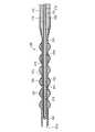
以下、本発明に係るスタイレット装置および医療用チューブ組立体について、図面を用いて説明する。図1は、本実施形態の医療用チューブ組立体の全体を示す正面図である。この医療用チューブ組立体1は、医療用チューブとしてのイレウスチューブ100と、スタイレット装置200を有する。イレウスチューブ100は、本体管部110と誘導部120とを備える。誘導部120は、イレウスチューブ100を経鼻的または経口的に体内腔に挿入するときに先頭になって体内腔を進み、本体管部110を患部まで誘導する部分であり、本体管部110の先端側(図示左端側)に設けられている。本体管部110は、誘導部120に後続する管状部材であり、患部内の内容物を外部に排出したり、外部から患部へ薬液を供給したりするときの通路として働く複数のルーメンが内部に形成される。本体管部110の図示左方寄りの外周には、バルーン130が取り付けられている。このバルーン130は、後述するバルーンルーメンから流体の供給を受けて膨張し、胃よりも下流の小腸等の内壁に当接するものである。なお、図ではバルーン130が膨張した状態を示しているが、イレウスチューブ100を体内腔に挿入する時にはバルーン130は収縮している。 Hereinafter, a stylet device and a medical tube assembly according to the present invention will be described with reference to the drawings. FIG. 1 is a front view showing the entire medical tube assembly of the present embodiment. The medical tube assembly 1 includes an
本体管部110の外周には、複数の吸入孔111が設けられている。さらに、本体管部110のバルーン130が取り付けられている部分よりも誘導部120に近い側の外周には、イリゲーション側孔112が設けられている。本体管部110の基端側は3本の分岐管(第一分岐管110a,第二分岐管110b,第三分岐管110c)に分岐している。また、スタイレット装置200は、長尺状に形成されたスタイレット210と、このスタイレット210の端部に接続した張力付与装置220とを備える。スタイレット210は、イレウスチューブ100を体内腔に挿入する際には図に示すように第一分岐管110aを経てイレウスチューブ100の内部に挿入されて、イレウスチューブ100の剛性を高める。 A plurality of suction holes 111 are provided on the outer periphery of the main
図2は、イレウスチューブ100の本体管部110の径方向断面図である。図2に示すように、本体管部110には、その中央部に体内の内容物を吸引して外部に排出するためのルーメンである吸引ルーメン113が形成されている。吸引ルーメン113の図示上側には、バルーン130に流体を供給するためのルーメンであるバルーンルーメン114が形成されている。さらに、吸引ルーメン113の図示下側には、体内腔が陰圧となるのを防止するために体内腔に空気を供給するためのルーメンであるイリゲーションルーメン115が形成されている。イリゲーションルーメン115は、体内に造影剤などの薬液を吐出するために用いられることもある。吸引ルーメン113は、本体管部110の軸方向に沿って形成されている。本体管部110の外周に形成された複数の吸入孔111は、この吸引ルーメン113に連通している。バルーンルーメン114は、吸引ルーメン113と並行に本体管部110の軸方向に沿って形成されており、バルーン130に連通している。イリゲーションルーメン115も吸引ルーメン113と並行に本体管部110の軸方向に沿って形成される。また、本体管部110の外周に形成されたイリゲーション側孔112は、このイリゲーションルーメン115に連通している。 FIG. 2 is a radial cross-sectional view of the main
吸引ルーメン113は、本体管部110の基端側から分岐した第一分岐管110aに連通し、バルーンルーメン114は第二分岐管110bに連通し、イリゲーションルーメン115は第三分岐管110cに連通する。図1に示すように第二分岐管110bの端部には弁110eが接続される。第三分岐管110cの端部には逆流防止弁110fが接続される。この逆流防止弁110fは、流体が外部から第三分岐管110c側に流れるのを許容し、流体が第三分岐管110c側から外部に流れるのを遮断する。第一分岐管110aの端部にはコネクタ110dが取り付けられている。そして、このコネクタ110dを介して、スタイレット装置200のスタイレット210が第一分岐管110aに挿入されている。スタイレット210は、図1からわかるようにイレウスチューブ100の先端側から後端側にかけて挿入可能な程度の長さを持つ長尺形状に形成される。 The
図3は、スタイレット210が挿入されたイレウスチューブ100の誘導部120付近の軸方向断面図である。図3に示すように、誘導部120は、本体管部110に連通した誘導管部121と、この誘導管部121の外周側を覆うように取り付けられた錘122とを備える。錘122は、球体に円柱状の孔を貫通したリング形状を呈している。誘導管部121には内部に通路121aが形成されている。この通路121aは、一端が本体管部110の吸引ルーメン113に連通し、他端が誘導管部121の先端開口121bにて外部に開口している。錘122は、誘導管部121の軸方向に沿って複数個(本例では6個)一定間隔を置いて取り付けられている。錘122の外周には軟質樹脂製のカバー123が被せられていて、このカバー123によって各錘122の軸方向移動が規制され、錘122は誘導管部121の所定位置に固定される。 FIG. 3 is an axial sectional view of the vicinity of the
スタイレット210は、コネクタ110dから第一分岐管110aに挿入され、さらに第一分岐管110aから本体管部110の吸引ルーメン113内、および、誘導管部121の通路121a内に挿入される(図3参照)。スタイレット210は、図3に示すように先端部211および本体部212を有する。先端部211は、スタイレット210の先端側に形成され、イレウスチューブ100の誘導管部121内の通路121aに挿入される部分である。本体部212は、先端部211に後続する部分であり、イレウスチューブ100の本体管部110の吸引ルーメン113内に挿入される。先端部211は、軟質樹脂(例えば軟質ポリウレタンや低密度ポリエチレン)で形成され、本体部212は、硬質樹脂(例えば硬質ポリウレタンや高密度ポリエチレン)で形成される。このため、先端部211は、屈曲または湾曲などの曲げ変形が可能とされる。 The
図4は、スタイレット210の径方向断面図、図5はスタイレット210の先端部211付近の軸方向断面図である。図4および図5に示すように、スタイレット210には、その略中央付近にルーメン213が長手方向に沿って形成されている。このルーメン213内には、補強用の芯線(図示省略)が挿入される。なお、ルーメン213内に芯線を挿入してスタイレット210を補強する他、芯線にプラスチック樹脂を被覆してスタイレットを作製するようにして、スタイレットを補強することもできる。 4 is a radial sectional view of the
図4に示すように、スタイレット210にはルーメン213を取り巻くように複数(本実施形態においては3個)の操作ワイヤ用ルーメン214a,214b,214c(以下、これらを総称するときには単に操作ワイヤ用ルーメン214と呼ぶ)が形成されている。これらの操作ワイヤ用ルーメン214a,214b,214cは、スタイレット210の軸心Oから偏倚した位置にて形成されている。また、操作ワイヤ用ルーメン214は、図5に示すようにスタイレット210の先端部211から本体部212にかけて長手方向に形成され、その一端がスタイレット210の先頭部216に近い位置にて閉塞され、その他端がスタイレット210の基端から開口している(図示省略)。各操作ワイヤ用ルーメン214a,214b,214c内にはそれぞれ操作ワイヤ215a,215b,215c(以下、これらを総称するときには単に操作ワイヤ215と呼ぶ)が挿入されている。操作ワイヤ215は、図5に示すようにその一端が操作ワイヤ用ルーメン214の閉塞端部を突き抜けて、スタイレット210の先頭部216に近い位置にてスタイレット210に固定されている。 As shown in FIG. 4, the
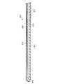
3本の操作ワイヤ215a,215b,215cが内挿されたスタイレット210は、図1に示すようにその基端側が張力付与装置220に接続されている。この張力付与装置220は、本実施形態ではボールペンのように長尺状に形成されている。図6は張力付与装置220の長手方向軸を含む面で切断した軸方向断面図、図7は図6のA−A断面拡大図である。これらの図に示すように、張力付与装置220は、丸棒状に形成された本体221を有する。この本体221には、軸方向に形成された通路222が周方向に等間隔で3箇所形成されている。また、本体221の外周に、軸方向に沿ってスリット状に切り欠いた窓部223が形成されている。この窓部223は、それぞれの通路222に連通するように周方向に等間隔で3箇所形成され、通路222の所定部分(図6においては左半分程度の部分)を開口するように、通路222に対面して設けられている。また、窓部223の幅は、通路222の幅よりも狭くされている。 The
本体221には操作レバー224が取り付けられている。この操作レバー224は、ガイド部224a、連結部224bおよび操作部224cを有している。ガイド部224aは、通路222内に挿入されて、通路222に沿って本体221の軸方向に移動可能とされる。連結部224bはガイド部224aから立設し、本体221の径外方に伸びて窓部223から外方に突出している。操作部224cは、連結部224bの径外方への突出部分に連結している。したがって、操作部224cを指で操作して窓部223に沿って移動させることにより、ガイド部224aを通路222内で移動させることができる。なお、操作レバー224は、3つの通路222に対応して、本体221の周方向に等間隔で3個設けられている。 An
図6に示すように、本体221の先端には蓋225が取り付けられている。蓋225は、内部が中空とされた砲弾状に形成されており、径の大きい端面側が本体221の端部に接続され、径の小さい端面側には開口225aが形成される。この開口225aには、スタイレット210が取り付けられている。スタイレット210の操作ワイヤ用ルーメン214には操作ワイヤ215が挿通しているが、この操作ワイヤ215はスタイレット210の基端から蓋225内の空間を経て本体221の通路222に進入している。そして、操作レバー224のガイド部224aにその端部が固定されている。このため、操作ワイヤ215は、その一端がスタイレット210の先端部211に固定されるとともに、その他端が操作レバー224に固定される。したがって、操作部224cを指で図6において右方向にスライドさせることにより操作ワイヤ215を引っ張って、操作ワイヤ215に張力を付与することができる。なお、通路222内にスプリングなどの付勢手段を配設し、操作レバー224をこの付勢手段によって付勢して、通常時は操作部224cが図6において左端側に配置するようにしてもよい。 As shown in FIG. 6, a
このような構成の医療用チューブ組立体1において、腸閉塞の治療または診察を行うときは、図1に示すようにスタイレット210をイレウスチューブ100内に挿入した状態で、誘導部120側から経鼻的または経口的にイレウスチューブ100を挿入する。すると、イレウスチューブ100は食道を通って胃まで達し、さらに幽門輪を経て胃を通過しようとする。このとき、幽門輪を越えるために、施術者は張力付与装置220の操作レバー224を操作し、操作部224cを図1において矢印B方向に移動する。すると、操作された操作レバー224に固定された操作ワイヤ215が引っ張られる。このため、引っ張られた操作ワイヤ215が緊張し、操作ワイヤ215に張力が付与される。この張力は、操作ワイヤ215の一端が固定されたスタイレット210に伝わる。ここで、図4に示すように、スタイレット210に形成される3つの操作ワイヤ用ルーメン214a,214b,214cはいずれもスタイレット210の軸心から偏倚した位置に設けられているので、操作ワイヤからの張力もスタイレット210の中心からずれてスタイレット210に伝わる。このため、スタイレット210は、張力が付与されている操作ワイヤ(例えば操作ワイヤ215a)が挿入される操作ワイヤ用ルーメン(例えば操作ワイヤ用ルーメン214a)の偏倚方向に縮もうとして、この方向に曲がる。 In the medical tube assembly 1 having such a configuration, when treating or diagnosing intestinal obstruction, the
ここで、スタイレット210の先端部211は軟質樹脂で形成され、先端部211に後続する本体部212は硬質樹脂で形成されており、先端部211は本体部212よりも剛性が低くなっている。したがって、上記張力によって、図8に示すように、スタイレット210の先端部211のみが曲がる。先端部211が曲がることによって、図9に示すように、先端部211が挿入されているイレウスチューブ100の誘導部120も先端部211と同じように曲がる。図10はこのときのイレウスチューブ100の誘導部120付近の軸方向断面図である。図10に示すように、スタイレット210の先端部211は、張力が付与された操作ワイヤ215が挿入された操作ワイヤ用ルーメン214が形成されている側が折れ込むように曲がっている。スタイレット210が曲がることによってその先端部211がイレウスチューブ100の誘導管部121に形成される通路121aの内壁に当接し、イレウスチューブ100にも曲げ力が付与されて、イレウスチューブ100の誘導部120が曲げられる。このような操作によって誘導部120を所望の方向に曲げることにより、誘導部120の先端が幽門輪の方向に向く。その状態でさらにイレウスチューブ100を進行させて、幽門輪を通過させる。その後、上記と同様な操作を行うことによって、トライツ靱帯などの屈曲した経路を持つ部位を通過して、イレウスチューブ100が小腸まで進行する。なお、イレウスチューブ100が屈曲した経路を進行中に経路の屈曲方向が変化したときは、操作すべき操作レバー224を変えて、変化した屈曲方向に対応させる。また、同時に二つの操作レバー224を操作すれば、片方ずつ操作したときに曲がる方向の中間の方向に誘導部120を曲げることができる。 Here, the
イレウスチューブ100の本体管部110が小腸等まで達した時点で、スタイレット210をイレウスチューブ100から抜き取る。そして、第二分岐管110bから流体をバルーンルーメン114に供給する。すると、流体がバルーンルーメン114を経てバルーン130に供給され、バルーン130が膨張して小腸等の内壁に当接する。このため、小腸等の蠕動運動がバルーン130にも伝わり、小腸等の蠕動運動によってイレウスチューブ100が小腸等内を進行する。そして、目的の位置までイレウスチューブ100が進行する。 When the main
目的の位置までイレウスチューブ100が進行したら、第一分岐管110aに吸引バックを接続し、この吸引バックを作動させて吸引ルーメン113内を陰圧にする。すると、誘導管部121の先端開口121bおよび本体管部110の吸入孔111から小腸等内の内容物が吸引ルーメン113内に取り込まれる。このように取り込まれた内容物は、吸引ルーメン113から第一分岐管110aを経て吸引バックに回収される。このようにして、腸閉塞等の治療を行う。 When the
図11は、イレウスチューブの誘導部の構造についての別例を示す図である。この医療用チューブは、誘導管部121内にスプリング124が配設されている。このように構成することにより、誘導管部121により弾性を持たすことができ、誘導管部121の全体をしなやかに曲げることができる。 FIG. 11 is a diagram showing another example of the structure of the guiding portion of the ileus tube. In this medical tube, a
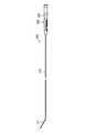
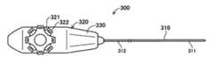
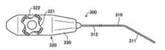
図12は、スタイレット装置の別例を示す平面図、図13は正面図である。このスタイレット装置300は、回動可能な2個の操作レバー(第一操作レバー321,第二操作レバー322)を備えた張力付与装置320を有する。第一および第二操作レバー321,322は、回動軸が同軸となるように上下に重ねて取り付けられている。図13に示すように、第一操作レバー321は、第一連結軸323を介して本体330内に配置される第一円盤プレート325に連結されていて、第一連結軸323を軸として第一円盤プレート325と一体回転するように構成されている。第二操作レバー322は、第二連結筒324を介して本体330内に配置される第二円盤プレート326に連結されていて、第二連結筒324を軸として第二円盤プレート326と一体回転するように構成されている。第二操作レバー322、第二連結筒324および第二円盤プレート326は、第一連結軸323を内挿しており、これらの組立体が第一連結軸323を軸として配置されているような構成とされている。第一円盤プレート325と第二円盤プレート326との間には、例えばベアリングなどが介在しており、両プレートは互いに独立に回転できるようになっている。 FIG. 12 is a plan view showing another example of the stylet device, and FIG. 13 is a front view. The
スタイレット310は、軟質樹脂で形成された先端部311および硬質樹脂で形成された本体部312を有し、本体部312の基端が張力付与装置320の本体330に取り付けられている。スタイレット310の径方向断面図を図14に示す。図14に示すように、スタイレット310は、その断面略中央に補強用の芯線(図示省略)が挿入されるルーメン313が形成され、このルーメン313の周囲に90度間隔で4個の操作ワイヤ用ルーメンが形成される。本実施形態では、図において右側に形成される操作ワイヤ用ルーメンを右ルーメン314r,左側に形成される操作ワイヤ用ルーメンを左ルーメン314l,上側に形成される操作ワイヤ用ルーメンを上ルーメン314u,下側に形成される操作ワイヤ用ルーメンを下ルーメン314d(以下、これらを総称するときは、単に操作ワイヤ用ルーメン314と呼ぶ)とする。操作ワイヤ用ルーメン314は、先端部311から本体部312にかけてスタイレット310の軸方向に沿って形成されている。また、これらの操作ワイヤ用ルーメン314r,314l,314u,314d内には、操作ワイヤ315r,315l,315u,315d(以下、これらを総称するときは、単に操作ワイヤ315と呼ぶ)が挿入される。操作ワイヤ315は、その一端がスタイレット310の先端部311に固定され、操作ワイヤ用ルーメン314を挿通し、その他端が第一円盤プレート325または第二円盤プレート326に固定される。 The
円盤プレート325,326には、スタイレット310の径方向断面(図14)から見て、ルーメン313に対して対称となる位置に形成される操作ワイヤ用ルーメン314内に挿入された操作ワイヤ315の端部が取り付けられる。例えば、第一円盤プレート325には右ルーメン314rおよび左ルーメン314lに挿入された操作ワイヤ315rおよび315lが固定され、第二円盤プレート326には上ルーメン314uおよび下ルーメン314dに挿入された操作ワイヤ315uおよび315dが固定される。また、円盤プレート325,326が一方向に回動したときにいずれか一方の操作ワイヤ315が引っ張られ、他方向に回動したときにいずれか他方の操作ワイヤ315が引っ張られるように、操作ワイヤ315が円盤プレート325,326に固定される。 In the
上記のように構成した場合、第一操作レバー321を回動操作すると、右ルーメン314rまたは左ルーメン314lに挿入された操作ワイヤ315rまたは315lに張力が付与されて、スタイレット310の先端部311が左右方向に曲がる(図15参照)。一方、第二操作レバー322を回動操作すると、上ルーメン314uまたは下ルーメン314dに挿入された操作ワイヤ315uまたは315dに張力が付与されて、スタイレット310の先端部311が上下方向に曲がる。また、第一および第二操作レバー321,322を同時に回動操作して、スタイレット310の先端を左上方向や、右下方向にも曲げることができる。 When configured as described above, when the
以上のように、本実施形態のスタイレット装置200,300は、長尺状に形成され、曲げ変形が可能であるとともに、内部に軸心から偏倚した径方向位置にて軸方向に沿って操作ワイヤ用ルーメン214,314が形成されたスタイレット210,310と、操作ワイヤ用ルーメン214,314内に挿入されて、一端がスタイレット210,310の先端部211,311に固定された操作ワイヤ215,315と、操作ワイヤ215,315の他端に接続されて操作ワイヤ215に張力を付与する張力付与装置220,320を備えている。そして、張力付与装置220,320の操作によってスタイレット210,310の先端部211,311が能動的に曲がるように構成される。このため、スタイレット210,310が挿入されるイレウスチューブ100の誘導部120を能動的に曲げることができる。よって、体内腔の複雑な経路であってもイレウスチューブ100を容易に通過させることができる。 As described above, the
また、スタイレット210は、その先端部211が軟質樹脂で形成され、本体部212が硬質樹脂で形成されており、先端部211が本体部212よりも剛性が低くされている。このため先端部211のみの曲げ変形を実現できる。また、スタイレット210の先端部211のみが曲がることによって、この先端部211が挿入されるイレウスチューブ100の誘導部120のみを曲げることができる。 The
以上、本発明の実施形態につき説明したが、本発明は上記実施形態に限定されることはない。例えば、上記の実施形態においては、イレウスチューブ100の誘導部120のみを曲げるためにスタイレット210の先端部211の剛性を本体部212の剛性よりも低くしているが、イレウスチューブ100の誘導部120の剛性を本体管部110の剛性より低くすることによっても、誘導部120のみを曲げることができる。この場合、誘導管部121を軟質樹脂で形成し、本体管部110を硬質樹脂で形成することによって、誘導部120の剛性を本体管部110の剛性よりも低くすることができる。また、誘導管部121と本体管部110とを同一材質で形成し、誘導管部121の外径を本体管部110の外径よりも小さくすることによっても、誘導部120の剛性を本体管部110の剛性よりも低くすることができる。また、上記の実施形態においては、スタイレット210の先端部211の剛性を本体部212の剛性よりも低くするために、先端部211を軟質樹脂で形成し、本体部212を硬質樹脂で形成しているが、それ以外の材料でも先端部211の剛性が本体部212の剛性よりも低くなるものであればよい。また、材質の変更以外にも、例えば先端部211の外径を本体部212の外径よりも小さくするなどの形状の変更によって、先端部211の剛性を本体部212の剛性よりも低くするようにしてもよい。また、スタイレット210の中央付近にルーメン213を設け、このルーメン213内に芯線が挿入されたものにあっては、ルーメン213のうち先端部211に形成される部分に挿入される芯線の径を、本体部212に形成される部分に挿入される芯線の径よりも小さくすることによっても、先端部211の剛性を本体部212の剛性よりも低くすることができる。 Although the embodiments of the present invention have been described above, the present invention is not limited to the above embodiments. For example, in the above embodiment, the rigidity of the
1…医療用チューブ組立体、100…イレウスチューブ(医療用チューブ)、110…本体管部、111…吸入孔、112…イリゲーション側孔、113…吸引ルーメン、114…バルーンルーメン、115…イリゲーションルーメン、120…誘導部、121…誘導管部、122…錘、130…バルーン、200,300…スタイレット装置、210,310…スタイレット、211,311…先端部、212,312…本体部、214,214a,214b,214c,314…操作ワイヤ用ルーメン、215,215a,215b,215c,315…操作ワイヤ、220,320…張力付与装置(張力付与手段)
DESCRIPTION OF SYMBOLS 1 ... Medical tube assembly, 100 ... Ileus tube (medical tube), 110 ... Main body pipe part, 111 ... Inhalation hole, 112 ... Illusion side hole, 113 ... Suction lumen, 114 ... Balloon lumen, 115 ... Illumination lumen, DESCRIPTION OF
Claims (8)
Translated fromJapanese前記操作ワイヤ用ルーメン内に挿通され、一端が前記スタイレットに固定された操作ワイヤと、
前記操作ワイヤの他端に接続されて前記操作ワイヤに張力を付与する張力付与手段と
を備えることを特徴とするスタイレット装置。A stylet that is formed in a long shape and can be bent and deformed, and a lumen for an operation wire is formed along the axial direction at a radial position deviated from the axial center inside,
An operation wire inserted into the operation wire lumen and having one end fixed to the stylet;
A stylet device comprising: tension applying means connected to the other end of the operation wire to apply tension to the operation wire.
複数の前記操作ワイヤ用ルーメンが前記スタイレットに形成され、複数の前記操作ワイヤ用ルーメンのうちの少なくとも2つ以上に前記操作ワイヤが挿通されていることを特徴とするスタイレット装置。The stylet device according to claim 1,
A stylet device, wherein a plurality of operation wire lumens are formed on the stylet, and the operation wires are inserted into at least two of the plurality of operation wire lumens.
前記スタイレットは、前記操作ワイヤの一端が固定される先端部と、前記先端部に接続した本体部を備え、前記先端部は前記本体部よりも剛性が低いことを特徴とするスタイレット装置。The stylet device according to claim 1 or 2,
The stylet device includes a distal end portion to which one end of the operation wire is fixed and a main body portion connected to the distal end portion, and the distal end portion has lower rigidity than the main body portion.
前記スタイレット装置のスタイレットが内部に挿入される医療用チューブと
を備えた医療用チューブ組立体。A stylet device according to claim 1 or 2,
A medical tube assembly comprising: a medical tube into which a stylet of the stylet device is inserted.
前記スタイレットは、前記操作ワイヤの一端が固定される先端部と、前記先端部に接続した本体部を備え、
前記医療用チューブは、前記本体部が挿入される本体管部と、前記先端部が挿入されるとともに前記本体管部を体内の内腔に誘導する誘導部とを備え、
前記張力付与手段により前記操作ワイヤに張力を付与したときに、前記誘導部が曲がることを特徴とする医療用チューブ組立体。The medical tube assembly according to claim 4,
The stylet includes a tip portion to which one end of the operation wire is fixed, and a main body portion connected to the tip portion,
The medical tube includes a main body tube portion into which the main body portion is inserted, and a guide portion that guides the main body tube portion into a body lumen while the distal end portion is inserted.
The medical tube assembly, wherein when the tension is applied to the operation wire by the tension applying means, the guide portion is bent.
前記誘導部は前記本体管部よりも剛性が低いことを特徴とする医療用チューブ組立体。The medical tube assembly according to claim 5,
The medical tube assembly according to claim 1, wherein the guide portion has lower rigidity than the main body tube portion.
前記先端部は前記本体部よりも剛性が低いことを特徴とする医療用チューブ組立体。The medical tube assembly according to claim 5 or 6,
The medical tube assembly according to claim 1, wherein the distal end portion has lower rigidity than the main body portion.
前記医療用チューブ内には複数のルーメンが形成されるとともにその外周にはバルーンが取り付けられ、
前記誘導部には錘が取り付けられていることを特徴とする医療用チューブ組立体。
The medical tube assembly according to any one of claims 5 to 7,
A plurality of lumens are formed in the medical tube and a balloon is attached to the outer periphery thereof.
A medical tube assembly, wherein a weight is attached to the guide portion.
Priority Applications (20)
| Application Number | Priority Date | Filing Date | Title |
|---|---|---|---|
| JP2006075473AJP4912705B2 (en) | 2006-03-17 | 2006-03-17 | Medical tube assembly |
| EP07002738AEP1834661B1 (en) | 2006-03-17 | 2007-02-08 | A stylet device and medical tube assembly |
| DE602007001814TDE602007001814D1 (en) | 2006-03-17 | 2007-02-08 | A stylet device and medical tubing set |
| ES07002738TES2330263T3 (en) | 2006-03-17 | 2007-02-08 | A SET OF STYLET DEVICE AND MEDICAL TUBE. |
| AT07002738TATE438433T1 (en) | 2006-03-17 | 2007-02-08 | A MANDRIN DEVICE AND MEDICAL TUBING SET |
| IL181377AIL181377A0 (en) | 2006-03-17 | 2007-02-15 | A stylet device and medical tube assembly |
| AU2007200841AAU2007200841B2 (en) | 2006-03-17 | 2007-02-26 | A stylet device and medical tube assembly |
| TW096106778ATWI318887B (en) | 2006-03-17 | 2007-02-27 | A stylet device and medical tube assembly |
| SG200701615-7ASG136047A1 (en) | 2006-03-17 | 2007-03-05 | A stylet device and medical tube assembly |
| US11/682,939US20070219499A1 (en) | 2006-03-17 | 2007-03-07 | Stylet Device and Medical Tube Assembly |
| NZ553769ANZ553769A (en) | 2006-03-17 | 2007-03-12 | A stylet device and medical tube assembly |
| CA002581836ACA2581836C (en) | 2006-03-17 | 2007-03-15 | A stylet device and medical tube assembly |
| PA20078719201APA8719201A1 (en) | 2006-03-17 | 2007-03-16 | STYLE DEVICE AND MEDICAL TUBE ASSEMBLY |
| ARP070101088AAR059926A1 (en) | 2006-03-17 | 2007-03-16 | A STYLET DEVICE AND MEDICAL TUBE ASSEMBLY |
| KR1020070026157AKR20070094561A (en) | 2006-03-17 | 2007-03-16 | Stylet Device and Medical Tube Assembly |
| CNA2007100885768ACN101036821A (en) | 2006-03-17 | 2007-03-16 | A stylet device and medical tube assembly |
| MX2007003168AMX2007003168A (en) | 2006-03-17 | 2007-03-16 | A stylet device and medical tube assembly . |
| CL200700687ACL2007000687A1 (en) | 2006-03-17 | 2007-03-16 | DEFORMABLE STYLET DEVICE, LONG AND PROVIDED WITH A LUMEN THAT PRESENTS A ACTUATING WIRE INSIDE THAT IS FIXED IN THE DISTAL END OF THE STYLET, AND A MECHANISM THAT CONFERS TENSION CONNECTED TO THE EXTREME PROXIMAL OF THE WIRE; |
| RU2007109879/14ARU2397785C2 (en) | 2006-03-17 | 2007-03-19 | Medical tube set and stiletto device for it |
| BRPI0702654-4ABRPI0702654A (en) | 2006-03-17 | 2007-03-19 | medical tube set and stylus device |
Applications Claiming Priority (1)
| Application Number | Priority Date | Filing Date | Title |
|---|---|---|---|
| JP2006075473AJP4912705B2 (en) | 2006-03-17 | 2006-03-17 | Medical tube assembly |
Publications (2)
| Publication Number | Publication Date |
|---|---|
| JP2007244771Atrue JP2007244771A (en) | 2007-09-27 |
| JP4912705B2 JP4912705B2 (en) | 2012-04-11 |
Family
ID=38068560
Family Applications (1)
| Application Number | Title | Priority Date | Filing Date |
|---|---|---|---|
| JP2006075473AExpired - Fee RelatedJP4912705B2 (en) | 2006-03-17 | 2006-03-17 | Medical tube assembly |
Country Status (20)
| Country | Link |
|---|---|
| US (1) | US20070219499A1 (en) |
| EP (1) | EP1834661B1 (en) |
| JP (1) | JP4912705B2 (en) |
| KR (1) | KR20070094561A (en) |
| CN (1) | CN101036821A (en) |
| AR (1) | AR059926A1 (en) |
| AT (1) | ATE438433T1 (en) |
| AU (1) | AU2007200841B2 (en) |
| BR (1) | BRPI0702654A (en) |
| CA (1) | CA2581836C (en) |
| CL (1) | CL2007000687A1 (en) |
| DE (1) | DE602007001814D1 (en) |
| ES (1) | ES2330263T3 (en) |
| IL (1) | IL181377A0 (en) |
| MX (1) | MX2007003168A (en) |
| NZ (1) | NZ553769A (en) |
| PA (1) | PA8719201A1 (en) |
| RU (1) | RU2397785C2 (en) |
| SG (1) | SG136047A1 (en) |
| TW (1) | TWI318887B (en) |
Cited By (8)
| Publication number | Priority date | Publication date | Assignee | Title |
|---|---|---|---|---|
| JP2012166031A (en)* | 2011-02-16 | 2012-09-06 | Biosense Webster Inc | Catheter with multiple deflections |
| JP2013048778A (en)* | 2011-08-31 | 2013-03-14 | Junken Medical株式会社 | Tubular organ treatment device |
| JP2014036771A (en)* | 2012-08-17 | 2014-02-27 | Hirosaki Univ | Assembly, insertion instrument and dilator |
| JP2014515644A (en)* | 2011-03-14 | 2014-07-03 | ニューロ エンタープライジズ,エルエルシー | Self-cleaning surgical suction device |
| JP2015181486A (en)* | 2014-03-20 | 2015-10-22 | テルモ株式会社 | catheter |
| KR101789448B1 (en) | 2016-12-07 | 2017-11-15 | 고려대학교 산학협력단 | Catheter unit with catheter and catheter guide for treating ectopic pregnancy |
| JP2020081016A (en)* | 2018-11-16 | 2020-06-04 | フォルテ グロウ メディカル株式会社 | Catheter, stylet and catheter kit |
| KR102560161B1 (en)* | 2022-05-18 | 2023-07-26 | 주식회사 유니코테크 | Angle-adjustable brush |
Families Citing this family (12)
| Publication number | Priority date | Publication date | Assignee | Title |
|---|---|---|---|---|
| WO2008121603A1 (en)* | 2007-03-30 | 2008-10-09 | Cook Critical Care Incorporated | Self-advanceable feeding tube |
| US8473034B2 (en) | 2011-03-04 | 2013-06-25 | Cook Medical Technologies Llc | System and method for feeding tube placement |
| US10098991B2 (en) | 2011-03-14 | 2018-10-16 | Neuroenterprises, Llc | Self-cleaning surgical suction device and method of use |
| US9144636B2 (en) | 2011-03-14 | 2015-09-29 | Neuroenterprises, Llc | Self-cleaning surgical suction device with interchangeable tips |
| CA2883616C (en) | 2011-08-25 | 2020-07-21 | H & M Innovations, Llc | Anti-clog suction tip apparatus and methods |
| US8845618B2 (en) | 2011-08-25 | 2014-09-30 | H & M Innovations, Llc | Anti-clog suction tip apparatus and method |
| CN104436329B (en)* | 2014-12-01 | 2017-01-11 | 广州市凌捷医疗器械有限公司 | Drainage device and using method thereof |
| SE1650363A1 (en)* | 2016-03-17 | 2017-09-18 | Madeleine Ramstedt | A catheter assembly |
| WO2018075797A1 (en)* | 2016-10-21 | 2018-04-26 | Through the Cords, LLC | Articulating stylet |
| GB2563567B (en) | 2017-05-05 | 2022-01-05 | Flexicare Group Ltd | Intubation devices |
| CN113384391B (en)* | 2021-06-30 | 2022-07-12 | 甘肃省人民医院 | Controllable stoma belt cleaning device of flow |
| WO2024077240A2 (en)* | 2022-10-07 | 2024-04-11 | Carilion Clinic | Suction device with improved ejection mechanism |
Citations (3)
| Publication number | Priority date | Publication date | Assignee | Title |
|---|---|---|---|---|
| US3605725A (en)* | 1968-08-07 | 1971-09-20 | Medi Tech Inc | Controlled motion devices |
| US5199950A (en)* | 1990-12-07 | 1993-04-06 | Willy Rusch Ag | Medical instrument |
| JPH08173541A (en)* | 1994-12-27 | 1996-07-09 | Fuji Syst Kk | Tube for ileus |
Family Cites Families (16)
| Publication number | Priority date | Publication date | Assignee | Title |
|---|---|---|---|---|
| US4207873A (en)* | 1977-05-16 | 1980-06-17 | American Cystoscope Makers, Inc. | Endoscope deflection control |
| SE455368B (en)* | 1986-11-11 | 1988-07-11 | Roger Hellgren | DEVICES FOR INTESTINAL ASPIRATION / PERFUSION |
| US4894056A (en)* | 1987-06-01 | 1990-01-16 | Bommarito Alexander A | Method and apparatus for clearing occluded lumens of enteral feeding tubes |
| US5083549A (en)* | 1989-02-06 | 1992-01-28 | Candela Laser Corporation | Endoscope with tapered shaft |
| US5795325A (en)* | 1991-07-16 | 1998-08-18 | Heartport, Inc. | Methods and apparatus for anchoring an occluding member |
| US5368564A (en)* | 1992-12-23 | 1994-11-29 | Angeion Corporation | Steerable catheter |
| US5396902A (en)* | 1993-02-03 | 1995-03-14 | Medtronic, Inc. | Steerable stylet and manipulative handle assembly |
| US5478309A (en)* | 1994-05-27 | 1995-12-26 | William P. Sweezer, Jr. | Catheter system and method for providing cardiopulmonary bypass pump support during heart surgery |
| JPH0889582A (en)* | 1994-09-28 | 1996-04-09 | Fuji Syst Kk | Catheter for medical treatment and its guiding method |
| US5824031A (en)* | 1996-02-28 | 1998-10-20 | Cardio Source | Apparatus and method for deflecting a tip of a lead or catheter |
| WO2001072368A2 (en)* | 2000-03-31 | 2001-10-04 | Medtronic, Inc. | Intralumenal visualization system with deflectable mechanism |
| US6530897B2 (en)* | 2000-04-28 | 2003-03-11 | Mahase Nardeo | Steerable medical catheter with bendable encapsulated metal spring tip fused to polymeric shaft |
| US6776765B2 (en)* | 2001-08-21 | 2004-08-17 | Synovis Life Technologies, Inc. | Steerable stylet |
| US6569114B2 (en)* | 2001-08-31 | 2003-05-27 | Biosense Webster, Inc. | Steerable catheter with struts |
| DE10158817A1 (en)* | 2001-11-30 | 2003-06-18 | Honeywell Speciality Chemicals | Removal system for filling and emptying containers |
| JP3852033B2 (en)* | 2003-12-12 | 2006-11-29 | 独立行政法人科学技術振興機構 | Active tube and active tube system |
- 2006
- 2006-03-17JPJP2006075473Apatent/JP4912705B2/ennot_activeExpired - Fee Related
- 2007
- 2007-02-08ATAT07002738Tpatent/ATE438433T1/ennot_activeIP Right Cessation
- 2007-02-08DEDE602007001814Tpatent/DE602007001814D1/enactiveActive
- 2007-02-08EPEP07002738Apatent/EP1834661B1/ennot_activeNot-in-force
- 2007-02-08ESES07002738Tpatent/ES2330263T3/enactiveActive
- 2007-02-15ILIL181377Apatent/IL181377A0/enunknown
- 2007-02-26AUAU2007200841Apatent/AU2007200841B2/ennot_activeCeased
- 2007-02-27TWTW096106778Apatent/TWI318887B/enactive
- 2007-03-05SGSG200701615-7Apatent/SG136047A1/enunknown
- 2007-03-07USUS11/682,939patent/US20070219499A1/ennot_activeAbandoned
- 2007-03-12NZNZ553769Apatent/NZ553769A/enunknown
- 2007-03-15CACA002581836Apatent/CA2581836C/ennot_activeExpired - Fee Related
- 2007-03-16CNCNA2007100885768Apatent/CN101036821A/enactivePending
- 2007-03-16CLCL200700687Apatent/CL2007000687A1/enunknown
- 2007-03-16KRKR1020070026157Apatent/KR20070094561A/ennot_activeCeased
- 2007-03-16ARARP070101088Apatent/AR059926A1/enunknown
- 2007-03-16PAPA20078719201Apatent/PA8719201A1/enunknown
- 2007-03-16MXMX2007003168Apatent/MX2007003168A/ennot_activeApplication Discontinuation
- 2007-03-19RURU2007109879/14Apatent/RU2397785C2/ennot_activeIP Right Cessation
- 2007-03-19BRBRPI0702654-4Apatent/BRPI0702654A/ennot_activeIP Right Cessation
Patent Citations (3)
| Publication number | Priority date | Publication date | Assignee | Title |
|---|---|---|---|---|
| US3605725A (en)* | 1968-08-07 | 1971-09-20 | Medi Tech Inc | Controlled motion devices |
| US5199950A (en)* | 1990-12-07 | 1993-04-06 | Willy Rusch Ag | Medical instrument |
| JPH08173541A (en)* | 1994-12-27 | 1996-07-09 | Fuji Syst Kk | Tube for ileus |
Cited By (9)
| Publication number | Priority date | Publication date | Assignee | Title |
|---|---|---|---|---|
| JP2012166031A (en)* | 2011-02-16 | 2012-09-06 | Biosense Webster Inc | Catheter with multiple deflections |
| JP2014515644A (en)* | 2011-03-14 | 2014-07-03 | ニューロ エンタープライジズ,エルエルシー | Self-cleaning surgical suction device |
| JP2013048778A (en)* | 2011-08-31 | 2013-03-14 | Junken Medical株式会社 | Tubular organ treatment device |
| JP2014036771A (en)* | 2012-08-17 | 2014-02-27 | Hirosaki Univ | Assembly, insertion instrument and dilator |
| JP2015181486A (en)* | 2014-03-20 | 2015-10-22 | テルモ株式会社 | catheter |
| KR101789448B1 (en) | 2016-12-07 | 2017-11-15 | 고려대학교 산학협력단 | Catheter unit with catheter and catheter guide for treating ectopic pregnancy |
| JP2020081016A (en)* | 2018-11-16 | 2020-06-04 | フォルテ グロウ メディカル株式会社 | Catheter, stylet and catheter kit |
| JP7117002B2 (en) | 2018-11-16 | 2022-08-12 | フォルテ グロウ メディカル株式会社 | catheter kit |
| KR102560161B1 (en)* | 2022-05-18 | 2023-07-26 | 주식회사 유니코테크 | Angle-adjustable brush |
Also Published As
| Publication number | Publication date |
|---|---|
| ATE438433T1 (en) | 2009-08-15 |
| CA2581836C (en) | 2010-02-02 |
| US20070219499A1 (en) | 2007-09-20 |
| IL181377A0 (en) | 2007-07-04 |
| CN101036821A (en) | 2007-09-19 |
| NZ553769A (en) | 2008-07-31 |
| CA2581836A1 (en) | 2007-09-17 |
| ES2330263T3 (en) | 2009-12-07 |
| RU2007109879A (en) | 2008-09-27 |
| TW200744692A (en) | 2007-12-16 |
| CL2007000687A1 (en) | 2008-02-08 |
| KR20070094561A (en) | 2007-09-20 |
| DE602007001814D1 (en) | 2009-09-17 |
| AU2007200841B2 (en) | 2008-11-13 |
| EP1834661B1 (en) | 2009-08-05 |
| PA8719201A1 (en) | 2008-11-19 |
| BRPI0702654A (en) | 2007-12-18 |
| SG136047A1 (en) | 2007-10-29 |
| TWI318887B (en) | 2010-01-01 |
| AR059926A1 (en) | 2008-05-07 |
| JP4912705B2 (en) | 2012-04-11 |
| EP1834661A1 (en) | 2007-09-19 |
| AU2007200841A1 (en) | 2007-10-04 |
| RU2397785C2 (en) | 2010-08-27 |
| MX2007003168A (en) | 2008-11-26 |
Similar Documents
| Publication | Publication Date | Title |
|---|---|---|
| JP4912705B2 (en) | Medical tube assembly | |
| KR100940692B1 (en) | Medical tube | |
| US20240366917A1 (en) | Helical balloon catheter | |
| US9820634B2 (en) | Integrated steering device | |
| JP5236472B2 (en) | Tip propulsion device moving through a passage | |
| US10058235B2 (en) | Steerable catheter | |
| US20150073391A1 (en) | Medical device with a movable tip | |
| JP2009513308A (en) | Steerable catheter device and method for articulating the catheter device | |
| CN113286542A (en) | Insertion unit for medical device and its intubation system | |
| JP2010035951A (en) | Catheter | |
| US20210251468A1 (en) | Medical device and treatment system | |
| JP6343574B2 (en) | catheter | |
| CN116328152A (en) | Balloon catheter |
Legal Events
| Date | Code | Title | Description |
|---|---|---|---|
| A621 | Written request for application examination | Free format text:JAPANESE INTERMEDIATE CODE: A621 Effective date:20090218 | |
| A131 | Notification of reasons for refusal | Free format text:JAPANESE INTERMEDIATE CODE: A131 Effective date:20110524 | |
| A521 | Request for written amendment filed | Free format text:JAPANESE INTERMEDIATE CODE: A523 Effective date:20110722 | |
| A131 | Notification of reasons for refusal | Free format text:JAPANESE INTERMEDIATE CODE: A131 Effective date:20110906 | |
| A521 | Request for written amendment filed | Free format text:JAPANESE INTERMEDIATE CODE: A523 Effective date:20111026 | |
| TRDD | Decision of grant or rejection written | ||
| A01 | Written decision to grant a patent or to grant a registration (utility model) | Free format text:JAPANESE INTERMEDIATE CODE: A01 Effective date:20120117 | |
| A01 | Written decision to grant a patent or to grant a registration (utility model) | Free format text:JAPANESE INTERMEDIATE CODE: A01 | |
| A61 | First payment of annual fees (during grant procedure) | Free format text:JAPANESE INTERMEDIATE CODE: A61 Effective date:20120118 | |
| R150 | Certificate of patent or registration of utility model | Free format text:JAPANESE INTERMEDIATE CODE: R150 | |
| FPAY | Renewal fee payment (event date is renewal date of database) | Free format text:PAYMENT UNTIL: 20150127 Year of fee payment:3 | |
| R250 | Receipt of annual fees | Free format text:JAPANESE INTERMEDIATE CODE: R250 | |
| R250 | Receipt of annual fees | Free format text:JAPANESE INTERMEDIATE CODE: R250 | |
| LAPS | Cancellation because of no payment of annual fees |