JP2007243398A - Television receiver - Google Patents
Television receiverDownload PDFInfo
- Publication number
- JP2007243398A JP2007243398AJP2006060834AJP2006060834AJP2007243398AJP 2007243398 AJP2007243398 AJP 2007243398AJP 2006060834 AJP2006060834 AJP 2006060834AJP 2006060834 AJP2006060834 AJP 2006060834AJP 2007243398 AJP2007243398 AJP 2007243398A
- Authority
- JP
- Japan
- Prior art keywords
- television receiver
- circuit
- wall surface
- sound
- interference
- Prior art date
- Legal status (The legal status is an assumption and is not a legal conclusion. Google has not performed a legal analysis and makes no representation as to the accuracy of the status listed.)
- Pending
Links
Images


Landscapes
- Television Receiver Circuits (AREA)
- Circuit For Audible Band Transducer (AREA)
Abstract
Translated fromJapaneseDescription
Translated fromJapanese本発明は、液晶ディスプレイ、プラズマディスプレイなどの薄型表示デバイスを有するテレビジョン受像機に関するものである。 The present invention relates to a television receiver having a thin display device such as a liquid crystal display or a plasma display.
ユーザの好みに応じて、或いはテレビジョン受像機の設置環境によって音声の各帯域のレベル調整をしてユーザの好みの通りに音場の補正する技術は実用とされている。 A technique for correcting the sound field according to the user's preference by adjusting the level of each band of the audio according to the user's preference or according to the installation environment of the television receiver has been put into practical use.
実用されている音声補正装置は、GUI等で表示される低域設定レベル(バス)、高域設定レベル(トレブル)などの項目を個別にユーザが設定レベルを上げ下げすることで調整するのが一般的である。 Audio correction devices in practical use are generally adjusted by the user individually raising or lowering the setting level, such as the low-frequency setting level (bus) and high-frequency setting level (treble) displayed on the GUI or the like. Is.
一方、視聴者のリスニングポイントに応じて任意のレベルで常に最適な臨場感のある音場を簡単に設定する手段は公知である(例えば、特許文献1参照)。 On the other hand, means for easily setting a sound field having an optimum presence always at an arbitrary level according to the listening point of the viewer is known (see, for example, Patent Document 1).
図7に示すように、システムコントローラ702により上下移動回路703、回転回路704及びレベル可変回路705を制御して、中高音スピーカキャビネット708の高音用、中音用スピーカユニット709、710を自分の耳の高さで、かつ、自分の方向を向くように調整したうえで、任意の発音レベルで発音する。これにより視聴者のリスニングポイントに応じて任意のレベルで常に最適な音場を簡単に設定できる技術例があるが、スピーカの位置を変更する点やテレビジョン受像機の設置後部の壁面との距離を音場設定には使用しないので本発明とは手段が異なる。また、スピーカの位置を変更する回路が必要であることは、コストアップの要因になるという問題を有する。
また従来の音声補正装置は、壁面からの距離によって低域が反射され、音声がこもることをユーザが認識し、意図的に低域設定レベル(バス)を絞るしか音声のこもりを回避する手段はなく、またどの程度低域設定レベルを絞れば、壁面からの反射の影響がないレベルになるのか感覚的な記憶に頼るしかなく、一度設置してしまえば正確に最適な補正量を決定することは困難であるという問題を有していた。 In addition, the conventional sound correction device has a means that the user recognizes that the low frequency is reflected by the distance from the wall surface and the sound is confined, and that the intention is to intentionally reduce the low frequency setting level (bus), the means for avoiding the sound confusion. No matter how much the low-frequency setting level is narrowed down, you can only rely on sensory memory to see if the level is not affected by reflection from the wall. Once installed, the optimum correction amount can be determined accurately. Had the problem of being difficult.
上記問題点を解決するために、本発明のテレビジョン受像機は、放送電波から特定チャンネルを選局して映像信号及び音声信号を得る選局回路と、各周辺回路を制御するマイクロコントローラと、テレビジョン受像機へのユーザ入力を受けるキー入力回路と、該選局回路から映像信号を受け信号の調整を行う映像信号処理回路と、画面に文字や図形を表示するRGB信号を発生するOSD表示回路と、該選局回路から音声信号を受け信号の調整を行う音声信号処理回路を備え、ユーザのリモコンボタン押下などキー入力回路に対する入力によるGUI操作などで、テレビジョン受像機本体と壁面までの距離を入力し、テレビジョン受像機本体と壁面までの距離から低域の反射音の干渉量をマイクロコントローラに判断させて、干渉が大きいときにはそれの量に応じて、該音声信号処理回路を制御して自動的に低域レベルを絞るようにする。 In order to solve the above problems, a television receiver of the present invention includes a channel selection circuit that selects a specific channel from broadcast radio waves to obtain a video signal and an audio signal, a microcontroller that controls each peripheral circuit, A key input circuit for receiving user input to the television receiver, a video signal processing circuit for receiving a video signal from the channel selection circuit and adjusting the signal, and an OSD display for generating RGB signals for displaying characters and figures on the screen Circuit, and an audio signal processing circuit that receives the audio signal from the channel selection circuit and adjusts the signal, and by a GUI operation by an input to the key input circuit, such as a user pressing a remote control button, to the television receiver main body and the wall surface When the distance is entered and the microcontroller determines the amount of low-frequency reflected sound interference based on the distance from the television receiver to the wall, The depending on the amount of it automatically to narrow the low level by controlling the voice signal processing circuit.
さらに上記構成にテレビジョン受像機と壁面までの距離計測できるセンサー回路を追加することで、ユーザがテレビジョン受像機と壁面までの距離を入力することなく干渉量をマイクロコントローラに判断させ、干渉が大きいときにはそれの量に応じて、該音声信号処理回路を制御して自動的に低域レベルを絞ることも可能である。 Furthermore, by adding a sensor circuit that can measure the distance from the television receiver to the wall surface in the above configuration, the user can determine the amount of interference without inputting the distance from the television receiver to the wall surface, When the frequency is large, it is possible to control the audio signal processing circuit according to the amount and automatically reduce the low frequency level.
以上のように本発明のテレビジョン受像機では、ユーザのリモコンボタン押下などキー入力回路に対する入力によるGUI操作などでテレビジョン受像機本体と壁面までの距離を入力するか、或いは、センサー等で自動的に計測することで、テレビジョン受像機本体と壁面までの距離から低域の反射音の干渉量を、マイクロコントローラに判断させて、干渉が大きいときにはそれの量に応じて、該音声信号処理回路を制御して自動的に低域レベルを絞るようにすることで、スピーカの位置を変更する回路によるコストアップも不要であり、ユーザに低域音声の壁面干渉を意識させずまた聴覚感覚に頼ることなく低域レベルを最適に設定して、音声のこもりを低減することできる。 As described above, in the television receiver of the present invention, the distance between the television receiver main body and the wall surface is input by a GUI operation by an input to the key input circuit such as a user pressing a remote control button, or automatically by a sensor or the like. By measuring automatically, the amount of interference of low-frequency reflected sound from the distance between the television receiver body and the wall surface is determined by the microcontroller, and when the interference is large, the audio signal processing is performed according to the amount of interference. By controlling the circuit to automatically reduce the low frequency level, there is no need to increase the cost by using a circuit that changes the position of the speaker. The low frequency level can be set optimally without reliance, and the volume of voice can be reduced.
本発明は、テレビジョン受像機の持つGUI画面にて、テレビジョン受像機の壁面からの設置距離をユーザに入力させるか、或いは、センサー等で自動的に計測し、音声の補正量そのものをユーザに意識させることなく最適に低域を絞ることで低域音声の干渉量を抑え、音声のこもりを低減することが最も主要な本発明の特徴である。 The present invention allows the user to input the installation distance from the wall surface of the television receiver on the GUI screen of the television receiver, or automatically measures with a sensor or the like, and the audio correction amount itself is determined by the user. The most important feature of the present invention is to suppress the amount of low-frequency speech interference and reduce the volume of speech by narrowing down the low frequency optimally without making the user conscious.
(実施の形態1)
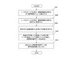
図1は、本発明の実施の形態1におけるテレビジョン受像機のブロック構成図である。テレビジョン受像機101は、受信放送電波から特定のチャンネルを選局して映像信号や音声信号を得る選局回路102、映像信号の調整を行う映像信号処理回路103、表示デバイス駆動回路104、音声信号の調整を行う音声信号処理回路105、音声出力回路106、マイクロコントローラ107、リモコンからのキー入力の受信や本体ボタンなどのキー入力回路108、ユーザに各種設定入力を促すGUIを表示するOSD表示回路109、映像やGUIを表示する表示部110、音声を出力するスピーカ111で構成されている。テレビジョン受像機101には、放送電波を受信する放送受信アンテナ120が接続されている。(Embodiment 1)
FIG. 1 is a block configuration diagram of a television receiver according to Embodiment 1 of the present invention. A
放送受信アンテナ120は、アナログの地上波または衛星放送、或いは、デジタルの地上波または衛星放送などの放送電波の受信を行い、選局回路102に受信信号を出力する。 The
選局回路102は、放送受信アンテナ101から受けた信号を増幅及び検波し、映像信号と音声信号に分離し、それぞれ映像信号処理回路103、音声信号処理回路105に出力する。 The
映像信号処理回路103は、選局回路102から受けた映像信号を調整したり、OSD表示回路109から送られる文字や図形を表すRGB信号を受けて、映像に重畳したりして、表示デバイス駆動回路104に調整されたRGB合成後の映像信号を出力する。 The video
表示デバイス駆動回路104は、映像信号処理回路103から受けた調整されたRGB合成後の映像信号を表示部110の形態に合わせて増幅して表示部110に出力する。 The display
音声信号処理回路105は、選局回路102から受けた音声信号を調整し、調整後の音声信号を音声出力回路106へ出力する。 The audio
音声出力回路106は音声信号処理回路105から調整後の音声信号を受け、スピーカ111の形態に合わせて増幅してスピーカ111へ出力する。 The
マイクロコントローラ107は、キー入力回路108からユーザのキー入力を受けて選局回路102を制御して、放送受信アンテナ120で受信した放送電波から任意のチャンネルを選局させる。またマイクロコントローラ107は、映像信号処理回路103を制御し、選局されたチャンネルの映像を表示デバイス駆動回路104に出力させて、ユーザの意図する映像ソースを表示部110に表示させたり、音声信号処理回路105を制御し、選局されたチャンネルの音声を音声出力回路106に出力させて、ユーザの意図する音声ソースをスピーカ111から出力させたりする。さらに、マイクロコントローラ107はOSD表示回路109を制御して、任意の文字や図形を表示部110に表示させることもできる。 The
キー入力回路108はリモコンからのキー入力の受信や本体ボタンなどユーザの入力を受けて、いずれのキーが押下されたかをマイクロコントローラ107に出力する。 The
OSD表示回路109はマイクロコントローラ107からの指示を受けて文字や図形などのRGB信号を発生させて、映像信号処理回路103へ出力する。 The
表示部110は、表示デバイス駆動回路104から入力した映像信号を表示するプラズマディスプレイや液晶ディスプレイなどの薄型表示デバイスである。 The
スピーカ111は、音声出力回路106から入力した音声信号の出力を行うデバイスである。 The
さて、薄型表示デバイスを持つテレビジョン受像機の設置場所と低域音声の干渉に関して図2及び図4を用いて説明する。 Now, the installation location of a television receiver having a thin display device and interference of low-frequency sound will be described with reference to FIGS.
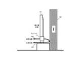
家庭内でのテレビジョン受像機の配置は、テレビジョンを視聴する部屋に対して壁面401に沿った形で配置することが一般的である。薄型表示デバイスをもつテレビジョン受像機101でも図4のように壁面401に沿った形で配置することが多い。そのとき、テレビジョン受像機101のスピーカ111も壁面401からの距離が非常に詰まった配置となり、その状態で番組を視聴されることになる。この場合、スピーカ111から発せられる低域音声は指向性がないため、低域音声の壁面401からの反射低音403とスピーカ111からの直接低音402が干渉し、音全体がこもることで、人物の声などが聞き取りにくくなる。 In general, the television receiver is arranged along the
次にこの低域音声の干渉による音のこもりを回避しようとする場合、壁面401によって低域が反射されて音声がこもることをユーザが認識し、例えば、図2の音声調整メニュー203などを表示部110に表示させ、ユーザが意図的にバス調整項目205の設定レベルを絞ることになるが、どの程度設定レベルを絞れば、壁面401からの反射の影響がないレベルになるのか、壁面401からの影響がある場合と無い場合との感覚的な比較に頼るしかなく、一度設置してしまえば正確に最適な補正量を決定することは困難であるという問題がある。 Next, when trying to avoid the accumulation of sound due to the interference of the low frequency sound, the user recognizes that the low frequency is reflected by the
前記のユーザの聴感上の感覚的な補正では最適な補正は困難であるという問題を回避する為には、ユーザが迷うことなく補正量の基準となる物理量をテレビジョン受像機に設定できるようにして補正量を自動設定できればよい。 In order to avoid the problem that the optimal correction is difficult by the above-described sensory correction on the user's perception, the user can set a physical quantity serving as a reference for the correction amount in the television receiver without hesitation. It is sufficient if the correction amount can be automatically set.
以上のように構成されたテレビジョン受像機について、以下図2及び図3のフローチャートも参照しながらその動作を説明する。 The operation of the television receiver configured as described above will be described below with reference to the flowcharts of FIGS.
マイクロコントローラ107が、ユーザからのリモコンや本体キー入力をキー入力回路108経由で受け、テレビジョン受像機101と壁面までの距離を設定する項目を持つGUI、例えば、図2の符号203で示されるような音声調整メニュー203をOSD表示回路109に指示を出して表示部110に表示させる(S301)。ユーザは表示された音声調整メニュー203の壁面距離設定項目204に対して、テレビジョン受像機101から壁面までの距離を設定する(S302)。設定されたテレビジョン受像機101と壁面までの距離をマイクロコントローラ107が解釈し、テレビジョン受像機101のスピーカ111から出る音声の低域の反射音の干渉量を計算する(S303)。マイクロコントローラ107はテレビジョン受像機101と壁面の距離が近いほど干渉量が大きいと判断するがその計算される干渉量から得られる低音補正量と、ユーザのバス調整項目から得られる低音調整量を加算し(S304)、音声信号処理回路105を制御して自動的に低域レベルを絞るようにする(S305)。このとき、テレビジョン後部に壁面が無い場合のユーザのバス調整項目の設定レベルのみによる聴感低音レベルと、テレビジョン後部に壁面がある場合のユーザ調整項目の設定レベルに前記干渉量から得られる低音補正量を加算したときの聴感低音レベルは同一レベルとなる。 A
S303の干渉量の求め方としては、音圧レベルは音源からの距離の2乗に反比例する特性から、(数1)の式から求められるように補正量を求めることができる(ただし吸音率αは無視するものとする)。 As a method of obtaining the amount of interference in S303, the correction amount can be obtained from the characteristic that the sound pressure level is inversely proportional to the square of the distance from the sound source as obtained from the equation (Equation 1) (however, the sound absorption rate α). Will be ignored).

またテレビジョン受像機などの民生機器では実際の高音レベル設定や低音レベル設定の精度から考えると、(数2)のように1次式近似することができる。 Further, in consumer equipment such as a television receiver, considering the accuracy of actual high sound level setting and low sound level setting, it can be approximated by a linear expression as shown in (Expression 2).
例えば具体的には、テレビジョン受像機101と壁面までの距離が60cm以下のとき、(数3)の補正を行う。 For example, specifically, when the distance between the
(数3)による補正量の算出の場合には、壁面から60cmの場所にテレビジョン受像機101を配置した場合に補正量0となり、10cmまで近づけて設置した場合に補正量は−5と算出される。この補正量をユーザによるバス設定レベルに加算して音声処理回路105を制御する。また、60cm以上離して設置した場合は補正量0である。 In the case of calculating the correction amount according to (Equation 3), the correction amount is 0 when the
また例えば実測に基づく正確な補正量を用いる場合には、壁面距離をインデックスとして、実測値データベースから参照して補正量を求める方法などもある。 For example, when an accurate correction amount based on actual measurement is used, there is a method of obtaining the correction amount by referring to the actual measurement value database using the wall surface distance as an index.
(実施の形態2)
図5は、本発明の実施の形態2におけるテレビジョン受像機のブロック構成図である。テレビジョン受像機501は、受信放送電波から特定のチャンネルを選局して映像信号や音声信号を得る選局回路502、映像信号の調整を行う映像信号処理回路503、表示デバイス駆動回路504、音声信号の調整を行う音声信号処理回路505、音声出力回路506、マイクロコントローラ507、リモコンや本体ボタンなどのキー入力回路508、ユーザに各種設定入力を促すGUIを表示するOSD表示回路509、テレビジョン受像機501の背面から壁面までの距離を計測することのできる壁面距離センサー510、映像やGUIを表示する表示部511、音声を出力するスピーカ512で構成されている。テレビジョン受像機501には、放送電波を受信する放送受信アンテナ520が接続されている。(Embodiment 2)
FIG. 5 is a block diagram of a television receiver according to Embodiment 2 of the present invention. The
放送受信アンテナ520は、アナログの地上波または衛星放送、或いは、デジタルの地上波または衛星放送などの放送電波の受信を行い、選局回路502に受信信号を出力する。 The
選局回路502は、放送受信アンテナ501から受けた信号を増幅及び検波し、映像信号と音声信号に分離し、それぞれ映像信号処理回路503、音声信号処理回路505に出力する。 The
映像信号処理回路503は、選局回路502から受けた映像信号を調整したり、OSD表示回路509から送られる文字や図形を表すRGB信号を受けて、映像に重畳したりして、表示デバイス駆動回路504に調整されたRGB合成後の映像信号を出力する。 The video
表示デバイス駆動回路504は、映像信号処理回路503から受けた調整されたRGB合成後の映像信号を表示部511の形態に合わせて増幅して表示部511に出力する。 The display
音声信号処理回路505は、選局回路502から受けた音声信号を調整し、調整後の音声信号を音声出力回路506へ出力する。 The audio
音声出力回路506は音声信号処理回路505から調整後の音声信号を受け、スピーカ512の形態に合わせて増幅してスピーカ512へ出力する。 The
マイクロコントローラ507は、キー入力回路508からユーザのキー入力を受けて選局回路502を制御して、放送受信アンテナ520で受信した放送電波から任意のチャンネルを選局させる。またマイクロコントローラ507は、映像信号処理回路503を制御し、選局されたチャンネルの映像を表示デバイス駆動回路504に出力させて、ユーザの意図する映像ソースを表示部511に表示させたり、音声信号処理回路505を制御し、選局されたチャンネルの音声を音声出力回路506に出力させて、ユーザの意図する音声ソースをスピーカ512から出力させたりする。さらに、マイクロコントローラ507はOSD表示回路509を制御して、任意の文字や図形を表示部511に表示させることもできる。 The
キー入力回路508はリモコンからのキー入力の受信や本体ボタンなどユーザの入力を受けて、いずれのキーが押下されたかをマイクロコントローラ507に出力する。 The
OSD表示回路509はマイクロコントローラ507からの指示を受けて文字や図形などのRGB信号を発生させて、映像信号処理回路503へ出力する。 The
壁面距離センサー510は、マイクロコントローラ507の制御を受け、計測したテレビジョン受像機501背面から壁面までの距離をマイクロコントローラ507に出力する。用いるセンサーとしては例えば小型の超音波センサーなどが挙げられる。 The wall
表示部511は、表示デバイス駆動回路104から入力した映像信号を表示するプラズマディスプレイや液晶ディスプレイなどの薄型表示デバイスである。 The
スピーカ512は、音声出力回路106から入力した音声信号の出力を行うデバイスである。 The
さて、薄型表示デバイスを持つテレビジョン受像機の設置場所と低域音声の干渉に関しては実施の形態1で述べた通りである。 Now, the installation location of the television receiver having the thin display device and the interference of the low frequency sound are as described in the first embodiment.
ユーザの聴感上の感覚的な補正では最適な補正は困難であるという問題を回避する為には、補正に必要な物理量を自動的に計測する回路を備えて、計測値から補正量を自動設定できればよい。 In order to avoid the problem that it is difficult to perform optimal correction with sensory correction on the user's perception, a circuit that automatically measures the physical quantity required for correction is provided, and the correction amount is automatically set from the measured value. I can do it.
以上のように構成されたテレビジョン受像機について、以下図2及び図6のフローチャートも参照しながらその動作を説明する。 The operation of the television receiver configured as described above will be described with reference to the flowcharts of FIGS.
マイクロコントローラ507は、壁面距離センサー510を制御し、テレビジョン受像機501の背面と壁面401までの距離を計測する(S601)。計測されたテレビジョン受像機501と壁面までの距離をマイクロコントローラ507が解釈し、テレビジョン受像機501のスピーカ512から出る音声の低域の反射音の干渉量を計算する(S602)。マイクロコントローラ507はテレビジョン受像機501と壁面の距離が近いほど干渉量が大きいと判断するがその計算される干渉量から得られる低音補正量と、ユーザのバス調整項目から得られる低音調整量を加算し(S603)、音声信号処理回路505を制御して自動的に低域レベルを絞るようにする(S604)。このとき、テレビジョン後部に壁面が無い場合のユーザの音声調整メニュー203のバス調整項目205の設定レベルのみによる聴感低音レベルと、テレビジョン後部に壁面がある場合のユーザ調整項目の設定レベルに前記干渉量から得られる低音補正量を加算したときの聴感低音レベルは同一レベルとなる。 The
S602の干渉量の求め方としては、音圧レベルは音源からの距離の2乗に反比例する特性から、(数4)の式から求められるように補正量を求めることができる(ただし吸音率αは無視するものとする)。 As a method of obtaining the amount of interference in S602, the correction amount can be obtained from the characteristic that the sound pressure level is inversely proportional to the square of the distance from the sound source, as obtained from the equation (Equation 4) (however, the sound absorption rate α). Will be ignored).
またテレビジョン受像機などの民生機器では実際の高音レベル設定や低音レベル設定の精度から考えると、(数5)のように1次式近似することができる。 In addition, in consumer equipment such as a television receiver, when considering the accuracy of actual high sound level setting and low sound level setting, a linear expression can be approximated as in (Equation 5).
例えば具体的には、テレビジョン受像機101と壁面までの距離が60cm以下のとき、(数6)の補正を行う。 For example, specifically, when the distance between the
(数6)による補正量の算出の場合には、壁面から60cmの場所にテレビジョン受像機501を配置した場合に補正量0となり、10cmまで近づけて設置した場合に補正量は−5と算出される。この補正量をユーザによるバス設定レベルに加算して音声処理回路505を制御する。また、60cm以上離して設置した場合は補正量0である。 In the case of calculating the correction amount according to (Equation 6), the correction amount becomes 0 when the
また例えば実測に基づく正確な補正量を用いる場合には、壁面距離をインデックスとして、実測値データベースから参照して補正量を求める方法などもある。 For example, when an accurate correction amount based on actual measurement is used, there is a method of obtaining the correction amount by referring to the actual measurement value database using the wall surface distance as an index.
前記のように、ユーザのリモコンボタン押下などキー入力回路に対する入力によるGUI操作などでテレビジョン受像機本体と壁面までの距離を入力するか、或いは、センサー等で自動的に計測することで、テレビジョン受像機と壁面までの距離から低域の反射音の干渉量を、マイクロコントローラに判断させて、干渉が大きいときにはそれの量に応じて、該音声信号処理回路を制御して自動的に低域レベルを絞るようにすることで、スピーカの位置を変更する回路によるコストアップも不要であり、ユーザに低域音声の壁面干渉を意識させずまた聴覚感覚に頼ることなく低域レベルを最適に設定して、音声のこもりを低減することできる。 As described above, the distance between the television receiver main body and the wall surface is input by a GUI operation or the like by input to the key input circuit such as a user pressing a remote control button, or is automatically measured by a sensor or the like. The amount of interference of low-frequency reflected sound from the distance between the receiver and the wall surface is determined by the microcontroller, and when the interference is large, the audio signal processing circuit is controlled automatically according to the amount of interference. By narrowing the range level, there is no need to increase the cost by using a circuit that changes the position of the speaker, and the low level level is optimized without making the user aware of the wall interference of the low frequency sound and relying on the auditory sense. It can be set to reduce the volume of voice.
また本発明は、壁面からの距離そのものをGUIによって入力させるのみならず、数種類の設定モードからユーザに選択させることで、簡易に干渉量を調整できるようにすることもできる。 Further, according to the present invention, not only the distance from the wall surface itself is input by the GUI, but also the interference amount can be easily adjusted by allowing the user to select from several setting modes.
また本発明は、テレビジョン受像機を設置する部屋環境のうち、後部の壁面までの距離を設定するのみならず、横方向の壁面の距離の設定を入力することで左右バランスを自動補正したり、床面からの設置の高さを入力することによって音質を調整したりすることも可能である。 Further, the present invention not only sets the distance to the rear wall in the room environment where the television receiver is installed, but also automatically corrects the left / right balance by inputting the setting of the horizontal wall distance. It is also possible to adjust the sound quality by inputting the height of installation from the floor.
101 テレビジョン受像機
102 選局回路
103 映像信号処理回路
104 表示デバイス駆動回路
105 音声信号処理回路
106 音声出力回路
107 マイクロコントローラ
108 キー入力回路
109 OSD表示回路
110 表示部
111 スピーカ
120 放送受信アンテナ
203 音声調整メニュー
204 壁面距離設定項目
205 バス調整項目
401 壁面
402 直接低音
403 反射低音
501 テレビジョン受像機
502 選局回路
503 映像信号処理回路
504 表示デバイス駆動回路
505 音声信号処理回路
506 音声出力回路
507 マイクロコントローラ
508 キー入力回路
509 OSD表示回路
510 壁面距離センサー
511 表示部
512 スピーカ
520 放送受信アンテナDESCRIPTION OF
Claims (2)
Translated fromJapanesePriority Applications (1)
| Application Number | Priority Date | Filing Date | Title |
|---|---|---|---|
| JP2006060834AJP2007243398A (en) | 2006-03-07 | 2006-03-07 | Television receiver |
Applications Claiming Priority (1)
| Application Number | Priority Date | Filing Date | Title |
|---|---|---|---|
| JP2006060834AJP2007243398A (en) | 2006-03-07 | 2006-03-07 | Television receiver |
Publications (1)
| Publication Number | Publication Date |
|---|---|
| JP2007243398Atrue JP2007243398A (en) | 2007-09-20 |
Family
ID=38588512
Family Applications (1)
| Application Number | Title | Priority Date | Filing Date |
|---|---|---|---|
| JP2006060834APendingJP2007243398A (en) | 2006-03-07 | 2006-03-07 | Television receiver |
Country Status (1)
| Country | Link |
|---|---|
| JP (1) | JP2007243398A (en) |
Cited By (7)
| Publication number | Priority date | Publication date | Assignee | Title |
|---|---|---|---|---|
| EP2037678A1 (en)* | 2007-09-11 | 2009-03-18 | Samsung Electronics Co., Ltd. | Method for equalizing audio, and video apparatus using the same |
| JP2009188474A (en)* | 2008-02-04 | 2009-08-20 | Canon Inc | Audio playback device and control method thereof |
| JP2011188220A (en)* | 2010-03-08 | 2011-09-22 | Toshiba Corp | Electronic apparatus and audio control method |
| EP2345241A4 (en)* | 2008-09-04 | 2012-02-29 | Shenzhen Tcl New Technology | System and method for adjusting television settings based on mounting scheme |
| JP2012511839A (en)* | 2008-12-09 | 2012-05-24 | コーニンクレッカ フィリップス エレクトロニクス エヌ ヴィ | How to adjust the sound output from a display device |
| KR20150094438A (en)* | 2014-02-11 | 2015-08-19 | 엘지전자 주식회사 | Display device and control method thereof |
| CN105532021A (en)* | 2013-08-28 | 2016-04-27 | 雅马哈株式会社 | Speaker device, audio reproduction system, and program |
- 2006
- 2006-03-07JPJP2006060834Apatent/JP2007243398A/enactivePending
Cited By (14)
| Publication number | Priority date | Publication date | Assignee | Title |
|---|---|---|---|---|
| EP2037678A1 (en)* | 2007-09-11 | 2009-03-18 | Samsung Electronics Co., Ltd. | Method for equalizing audio, and video apparatus using the same |
| US8600075B2 (en) | 2007-09-11 | 2013-12-03 | Samsung Electronics Co., Ltd. | Method for equalizing audio, and video apparatus using the same |
| JP2009188474A (en)* | 2008-02-04 | 2009-08-20 | Canon Inc | Audio playback device and control method thereof |
| EP2345241A4 (en)* | 2008-09-04 | 2012-02-29 | Shenzhen Tcl New Technology | System and method for adjusting television settings based on mounting scheme |
| JP2012511839A (en)* | 2008-12-09 | 2012-05-24 | コーニンクレッカ フィリップス エレクトロニクス エヌ ヴィ | How to adjust the sound output from a display device |
| JP2011188220A (en)* | 2010-03-08 | 2011-09-22 | Toshiba Corp | Electronic apparatus and audio control method |
| EP3041273A4 (en)* | 2013-08-28 | 2017-05-03 | Yamaha Corporation | Speaker device, audio reproduction system, and program |
| CN105532021A (en)* | 2013-08-28 | 2016-04-27 | 雅马哈株式会社 | Speaker device, audio reproduction system, and program |
| CN106030505A (en)* | 2014-02-11 | 2016-10-12 | Lg电子株式会社 | Display device and control method thereof |
| KR20150094438A (en)* | 2014-02-11 | 2015-08-19 | 엘지전자 주식회사 | Display device and control method thereof |
| EP3105673A4 (en)* | 2014-02-11 | 2017-10-18 | LG Electronics Inc. | Display device and control method thereof |
| US10089062B2 (en) | 2014-02-11 | 2018-10-02 | Lg Electronics Inc. | Display device and control method thereof |
| CN106030505B (en)* | 2014-02-11 | 2019-06-04 | Lg电子株式会社 | Display device and its control method |
| KR102293654B1 (en)* | 2014-02-11 | 2021-08-26 | 엘지전자 주식회사 | Display device and control method thereof |
Similar Documents
| Publication | Publication Date | Title |
|---|---|---|
| US9740279B2 (en) | Method for adjusting volume of a display device and a display device | |
| JP2007243398A (en) | Television receiver | |
| RU2559748C2 (en) | Display and audio output device | |
| EP3157169B1 (en) | Audio system, audio device, mobile terminal device and audio signal control method | |
| JP4535006B2 (en) | Television equipment | |
| US20090129604A1 (en) | Sound field control method and system | |
| KR20100042370A (en) | Fitting system of digital hearing aid to be capable of changing frequency band and channel | |
| JP2001352600A (en) | Remote controller, receiver and audio system | |
| JP5499469B2 (en) | Audio output device, video / audio reproduction device, and audio output method | |
| US20120230525A1 (en) | Audio device and audio system | |
| JP2007306275A (en) | Sound output device, television receiver | |
| KR20160098649A (en) | Sweet spot setting device for speaker and method thereof | |
| KR101672210B1 (en) | Audio system and method of operating the same | |
| US20210297797A1 (en) | Audition of hearing device settings, associated system and hearing device | |
| KR102522567B1 (en) | Electronic apparatus and operating method for the same | |
| JP2014202808A (en) | Input/output device | |
| JP2009147813A (en) | Acoustic system, and setting method of acoustic system | |
| JP2016048838A (en) | Broadcast receiver | |
| JP2011103543A (en) | Audio output device and television receiver | |
| JP4077436B2 (en) | Hearing aid adjustment system and hearing aid adjustment device | |
| JP2014039255A (en) | Hand-held device and control method thereof | |
| KR20080055303A (en) | Display device and control method of display device | |
| US12137332B2 (en) | Audio device and operation method thereof | |
| JP2008177893A (en) | Multi-screen display television receiver, remote control device and headphone device | |
| JP2018084843A (en) | Input/output device |