JP2007243135A - Illumination device and display device including the same - Google Patents
Illumination device and display device including the sameDownload PDFInfo
- Publication number
- JP2007243135A JP2007243135AJP2006200347AJP2006200347AJP2007243135AJP 2007243135 AJP2007243135 AJP 2007243135AJP 2006200347 AJP2006200347 AJP 2006200347AJP 2006200347 AJP2006200347 AJP 2006200347AJP 2007243135 AJP2007243135 AJP 2007243135A
- Authority
- JP
- Japan
- Prior art keywords
- light
- phosphor
- blue
- color converter
- green
- Prior art date
- Legal status (The legal status is an assumption and is not a legal conclusion. Google has not performed a legal analysis and makes no representation as to the accuracy of the status listed.)
- Granted
Links
Images


Classifications
- G—PHYSICS
- G02—OPTICS
- G02B—OPTICAL ELEMENTS, SYSTEMS OR APPARATUS
- G02B6/00—Light guides; Structural details of arrangements comprising light guides and other optical elements, e.g. couplings
- G02B6/0001—Light guides; Structural details of arrangements comprising light guides and other optical elements, e.g. couplings specially adapted for lighting devices or systems
- G02B6/0011—Light guides; Structural details of arrangements comprising light guides and other optical elements, e.g. couplings specially adapted for lighting devices or systems the light guides being planar or of plate-like form
- G02B6/0013—Means for improving the coupling-in of light from the light source into the light guide
- G02B6/0023—Means for improving the coupling-in of light from the light source into the light guide provided by one optical element, or plurality thereof, placed between the light guide and the light source, or around the light source
- G—PHYSICS
- G02—OPTICS
- G02B—OPTICAL ELEMENTS, SYSTEMS OR APPARATUS
- G02B6/00—Light guides; Structural details of arrangements comprising light guides and other optical elements, e.g. couplings
- G02B6/0001—Light guides; Structural details of arrangements comprising light guides and other optical elements, e.g. couplings specially adapted for lighting devices or systems
- G02B6/0011—Light guides; Structural details of arrangements comprising light guides and other optical elements, e.g. couplings specially adapted for lighting devices or systems the light guides being planar or of plate-like form
- G02B6/0066—Light guides; Structural details of arrangements comprising light guides and other optical elements, e.g. couplings specially adapted for lighting devices or systems the light guides being planar or of plate-like form characterised by the light source being coupled to the light guide
- G02B6/0068—Arrangements of plural sources, e.g. multi-colour light sources
- H—ELECTRICITY
- H01—ELECTRIC ELEMENTS
- H01L—SEMICONDUCTOR DEVICES NOT COVERED BY CLASS H10
- H01L2224/00—Indexing scheme for arrangements for connecting or disconnecting semiconductor or solid-state bodies and methods related thereto as covered by H01L24/00
- H01L2224/01—Means for bonding being attached to, or being formed on, the surface to be connected, e.g. chip-to-package, die-attach, "first-level" interconnects; Manufacturing methods related thereto
- H01L2224/42—Wire connectors; Manufacturing methods related thereto
- H01L2224/44—Structure, shape, material or disposition of the wire connectors prior to the connecting process
- H01L2224/45—Structure, shape, material or disposition of the wire connectors prior to the connecting process of an individual wire connector
- H01L2224/45001—Core members of the connector
- H01L2224/45099—Material
- H01L2224/451—Material with a principal constituent of the material being a metal or a metalloid, e.g. boron (B), silicon (Si), germanium (Ge), arsenic (As), antimony (Sb), tellurium (Te) and polonium (Po), and alloys thereof
- H01L2224/45138—Material with a principal constituent of the material being a metal or a metalloid, e.g. boron (B), silicon (Si), germanium (Ge), arsenic (As), antimony (Sb), tellurium (Te) and polonium (Po), and alloys thereof the principal constituent melting at a temperature of greater than or equal to 950°C and less than 1550°C
- H01L2224/45144—Gold (Au) as principal constituent
- H—ELECTRICITY
- H01—ELECTRIC ELEMENTS
- H01L—SEMICONDUCTOR DEVICES NOT COVERED BY CLASS H10
- H01L2224/00—Indexing scheme for arrangements for connecting or disconnecting semiconductor or solid-state bodies and methods related thereto as covered by H01L24/00
- H01L2224/01—Means for bonding being attached to, or being formed on, the surface to be connected, e.g. chip-to-package, die-attach, "first-level" interconnects; Manufacturing methods related thereto
- H01L2224/42—Wire connectors; Manufacturing methods related thereto
- H01L2224/47—Structure, shape, material or disposition of the wire connectors after the connecting process
- H01L2224/48—Structure, shape, material or disposition of the wire connectors after the connecting process of an individual wire connector
- H01L2224/4805—Shape
- H01L2224/4809—Loop shape
- H01L2224/48091—Arched
- H—ELECTRICITY
- H01—ELECTRIC ELEMENTS
- H01L—SEMICONDUCTOR DEVICES NOT COVERED BY CLASS H10
- H01L2224/00—Indexing scheme for arrangements for connecting or disconnecting semiconductor or solid-state bodies and methods related thereto as covered by H01L24/00
- H01L2224/01—Means for bonding being attached to, or being formed on, the surface to be connected, e.g. chip-to-package, die-attach, "first-level" interconnects; Manufacturing methods related thereto
- H01L2224/42—Wire connectors; Manufacturing methods related thereto
- H01L2224/47—Structure, shape, material or disposition of the wire connectors after the connecting process
- H01L2224/48—Structure, shape, material or disposition of the wire connectors after the connecting process of an individual wire connector
- H01L2224/484—Connecting portions
- H01L2224/48463—Connecting portions the connecting portion on the bonding area of the semiconductor or solid-state body being a ball bond
- H01L2224/48464—Connecting portions the connecting portion on the bonding area of the semiconductor or solid-state body being a ball bond the other connecting portion not on the bonding area also being a ball bond, i.e. ball-to-ball
- H—ELECTRICITY
- H10—SEMICONDUCTOR DEVICES; ELECTRIC SOLID-STATE DEVICES NOT OTHERWISE PROVIDED FOR
- H10H—INORGANIC LIGHT-EMITTING SEMICONDUCTOR DEVICES HAVING POTENTIAL BARRIERS
- H10H20/00—Individual inorganic light-emitting semiconductor devices having potential barriers, e.g. light-emitting diodes [LED]
- H10H20/80—Constructional details
- H10H20/85—Packages
- H10H20/851—Wavelength conversion means
- H10H20/8511—Wavelength conversion means characterised by their material, e.g. binder
- H10H20/8512—Wavelength conversion materials
- H10H20/8513—Wavelength conversion materials having two or more wavelength conversion materials
Landscapes
- Physics & Mathematics (AREA)
- General Physics & Mathematics (AREA)
- Optics & Photonics (AREA)
- Planar Illumination Modules (AREA)
- Led Device Packages (AREA)
- Led Devices (AREA)
Abstract
Translated fromJapaneseDescription
Translated fromJapanese本発明は、非自発光型の表示素子を照明する照明装置、及び、電子機器に用いられる表示装置に関する。特に、携帯情報機器や携帯電話などに用いられる液晶表示装置、及び表示素子を照明するフロントライトやバックライト等の照明装置に関する。 The present invention relates to an illumination device that illuminates a non-self-luminous display element, and a display device used in an electronic apparatus. In particular, the present invention relates to a liquid crystal display device used for a portable information device, a mobile phone, and the like, and an illumination device such as a front light and a backlight for illuminating a display element.
近年の携帯電話やモバイルコンピュータなどに用いられる表示装置には、高精彩カラー画像が少ない消費電力で得られる液晶表示装置が多く用いられている。液晶表示装置に用いられる液晶素子は非自発光型であるため、高輝度の白色LEDを光源とする照明装置を用いて液晶素子を照明している。 2. Description of the Related Art Liquid crystal display devices that can obtain high-definition color images with low power consumption are often used for display devices used in recent mobile phones and mobile computers. Since the liquid crystal element used in the liquid crystal display device is a non-self-luminous type, the liquid crystal element is illuminated using an illumination device that uses a high-intensity white LED as a light source.
特に携帯電話においては、開口が大きく明るい反射型液晶表示装置や、表裏両面から画像情報を表示することが可能な両面可視型液晶表示装置が用いられている。これらの表示素子の照明に用いられている白色LEDは、InGaN系やGaN系等の青色LEDの発光面の直前に黄色蛍光体を分散した樹脂が設けられた構成である。この構成によれば、黄色光と元の青色光とを混色させて白色光を得ることができる。青色光を黄色光に変換する蛍光体としては、YAG(イットリウム・アルミニウム・ガーネット)に希土類元素をドープしたYAG蛍光体が良く知られている。また、YAG蛍光体の代わりに赤色と緑色発光蛍光体を調合し、青と赤と緑の加法混色により白色光を作る手法も知られている(例えば、特許文献1を参照)。青色光を緑色光や赤色光に比較的高効率に変換する蛍光体としては希土をドープしたカルコゲナイド系蛍光体や窒化物蛍光体が良く知られている。また、回路を形成した任意の形状および面積のプリント基板上に青色光の波長以下の波長の光を発光する複数の発光素子を配置し、各発光素子を波長変換材料が含有された透光性樹脂で被覆したLED表示用デバイスが開示されている(例えば、特許文献2を参照)。
しかしながら、青色LEDとYAG蛍光体の二色の加法混色(擬似白色LED)では、600nm以上の波長領域の光成分は少ない。そのため、高い色再現性を有するLCDモジュールが実現できない。一般的に、現在のカラーフィルタでは、擬似白色LEDを光源とする場合、NTSC比率100%を超えることは非常に困難とされている。また、特許文献1のように、青色励起で緑色光と赤色光のそれぞれに変換する二種類の蛍光体を青色LEDの発光面に滴下する構成によれば、三色の加法混色(三波長白色LED)が可能になり、高い色再現性を有するLCDモジュールが実現できる。しかし、希土類元素をドープしたカルコゲナイド系蛍光体の場合、LED内部の反射膜の化学反応を起こし、反射特性を劣化させる不具合を生じる事が多い。また、緑色蛍光体と赤色蛍光体を混合し、この混合体で青色を励起して白色光を作る際、赤色蛍光体として窒化物蛍光体やカルコゲナイド系蛍光体を用いる場合がある。これらの蛍光体には、緑色蛍光体で発光する緑色光も励起波長に含んでいるため、輝度効率が低いという課題がある。 However, in the additive color mixture of two colors of blue LED and YAG phosphor (pseudo white LED), the light component in the wavelength region of 600 nm or more is small. Therefore, an LCD module having high color reproducibility cannot be realized. Generally, in the current color filter, when a pseudo white LED is used as a light source, it is very difficult to exceed the NTSC ratio of 100%. Moreover, according to the configuration in which two types of phosphors that are converted into green light and red light by blue excitation are dropped onto the light emitting surface of a blue LED as in
そこで、本発明は、三色の加法混色で高い色再現性を得ると同時に輝度効率及び信頼性の高い照明装置を実現することを目的とする。すなわち、本発明の照明装置は、青色励起で赤色光に変換する第一の色変換体を、青色励起で緑色光に変換する第二の色変換体と青色発光素子との間の光路中に、第二の色変換体とは分離して設けた構成である。このような構成により、青色発光素子の青色発光と第一の色変換体により変換された赤色光が混色して紫色光になり、さらに、青色励起で第二の色変換体に変換された緑色光と混色して白色光が得られる。このような変換順で発光素子からの光が白色になるため、第二の色変換体に含まれる緑色蛍光体からの発光が第一の色変換体に含まれる赤色蛍光体に届くことがなく、照明装置の発光効率が上昇する。また、青色発光素子と緑色蛍光体が完全に分離されているので、緑色蛍光体が発光素子に科学的影響を与えること、または受けることがなく、信頼性が向上する。 SUMMARY OF THE INVENTION Accordingly, an object of the present invention is to realize a lighting device having high luminance efficiency and high reliability while obtaining high color reproducibility by additive color mixing of three colors. That is, the illumination device of the present invention is configured such that the first color conversion body that converts red light by blue excitation into the light path between the second color conversion body that converts green light by blue excitation and the blue light emitting element. The second color converter is provided separately. With such a configuration, the blue light emission of the blue light emitting element and the red light converted by the first color converter are mixed to become purple light, and further, the green color converted into the second color converter by blue excitation. White light is obtained by mixing with light. Since the light from the light emitting element becomes white in such a conversion order, the light emission from the green phosphor included in the second color converter does not reach the red phosphor included in the first color converter. The luminous efficiency of the lighting device is increased. In addition, since the blue light emitting element and the green phosphor are completely separated, the green phosphor does not scientifically affect or receive the light emitting element, and the reliability is improved.
また、本発明の表示装置は、上述したいずれかの構成の照明装置と、照明装置の照射面側に設けられた非自発光型の表示素子と、を備えている。 The display device of the present invention includes the illumination device having any one of the above-described configurations and a non-self-luminous display element provided on the irradiation surface side of the illumination device.
あるいは、本発明の表示装置は、青色発光素子と、非自発光型の表示素子と、青色発光素子から入射された光を出光面から表示素子に向けて出射する導光体と、青色発光素子と表示素子の間の光路中に設けられた赤色発光蛍光体と、赤色発光蛍光体と表示素子の間の光路中に設けられた緑色発光蛍光体を備えている。 Alternatively, the display device of the present invention includes a blue light-emitting element, a non-self-luminous display element, a light guide that emits light incident from the blue light-emitting element toward the display element from the light-emitting surface, and the blue light-emitting element. And a red light emitting phosphor provided in the optical path between the display element and a green light emitting phosphor provided in the optical path between the red light emitting phosphor and the display element.
あるいは、本発明の表示装置は、青色発光素子の発光を用いて非自発光型の表示素子を照明する表示装置であって、青色励起で赤色光に変換する第一の色変換体と、青色励起で緑色光に変換する第二の色変換体を備えるとともに、第一の色変換体と第二の色変換体が青色発光素子と表示素子の間の光路中に分離して設けられている。 Alternatively, the display device of the present invention is a display device that illuminates a non-self-luminous display element using light emitted from a blue light-emitting element, and includes a first color converter that converts red light by blue excitation, and blue A second color converter that converts green light by excitation is provided, and the first color converter and the second color converter are separately provided in the optical path between the blue light emitting element and the display element. .
本発明の照明装置は、第二色変換体から発光された緑色光が第一色変換体の励起光となることなく、青色と赤色と緑色の三色の加法混色による白色光を得ることができる。そのため、発光効率の高い照明装置が実現できる。また、LED素子と第二色変換体を分離しているのでLEDパッケージ内部の反射特性の劣化を起こすこともない。そのため、長寿命の照明装置が実現できる。さらに、本発明の照明装置をLCDパネルと組み合わせることで、色再現性が高く、高輝度で長寿命の液晶表示装置が実現できる。 The illuminating device of the present invention can obtain white light by additive color mixture of three colors of blue, red, and green without the green light emitted from the second color converter becoming the excitation light of the first color converter. it can. Therefore, a lighting device with high luminous efficiency can be realized. Moreover, since the LED element and the second color converter are separated, the reflection characteristics inside the LED package are not deteriorated. Therefore, a long-life lighting device can be realized. Further, by combining the lighting device of the present invention with an LCD panel, a liquid crystal display device with high color reproducibility, high luminance and long life can be realized.
本発明の照明装置は、青色発光素子、青色励起で赤色光に変換する第一色変換体、青色励起で緑色光に変換する第二色変換体を備えており、第一色変換体は、青色発光素子と第二色変換体の間の光路中に第二色変換体とは分離して設けられている。このような構成を図1に模式的に示す。すなわち、第一色変換体1と第二色変換体2は照明装置の光路中に分離して設けられている。図1では、青色発光素子からの光を導いて出光面から出射する導光体4が第一色変換体1と第二色変換体2の間に設けられており、青色発光素子1と導光体4の間に第一色変換体1が設けられている。このような構成により、青色発光素子3の青色発光と第一色変換体1により変換された赤色光が混色された後、さらに、第二色変換体により変換された緑色光と混色して白色光が得られる。このような変換順で白色が作製されるので、第二色変換体に含まれる緑色蛍光体からの発光が第一色変換体に含まれる赤色蛍光体の励起光となることがなく、照明装置としての発光効率が上昇する。また、青色発光素子と第二色変換体に含まれる緑色蛍光体が完全に分離されているので、緑色蛍光体が発光素子に科学的影響を与えることも受けることもなく、温度−輝度特性や信頼性が向上する。 The illumination device of the present invention includes a blue light emitting element, a first color converter that converts red light by blue excitation, and a second color converter that converts green light by blue excitation. The second color converter is provided separately in the optical path between the blue light emitting element and the second color converter. Such a configuration is schematically shown in FIG. That is, the
さらに、本発明の照明装置は、青色発光素子で発光した光を出光面に導く導光体を備えている。そして、第一色変換体は青色光で励起して赤色光を発光する赤色蛍光体を含んでおり、第二色変換体は青色光で励起して緑色光を発光する緑色蛍光体を含んでいる。ここで、緑色蛍光体は、青色発光素子と赤色蛍光体から分離していればよい。すなわち、緑色蛍光体は導光体中に存在しても、導光体の出光面側に設けられてもよい。後者の場合、導光体の出光面に設けられた樹脂中やフィルム中に存在する構成、あるいは、導光体の出光面側にフィルムを設け、このフィルム上に形成された樹脂中に存在する構成等が例示できる。 Furthermore, the illumination device of the present invention includes a light guide that guides light emitted from the blue light emitting element to the light exit surface. The first color converter includes a red phosphor that emits red light when excited by blue light, and the second color converter includes a green phosphor that emits green light when excited by blue light. Yes. Here, the green phosphor may be separated from the blue light emitting element and the red phosphor. That is, the green phosphor may be present in the light guide or provided on the light exit surface side of the light guide. In the latter case, the structure exists in the resin or film provided on the light exit surface of the light guide, or the film is provided on the light exit surface side of the light guide and exists in the resin formed on the film. A configuration etc. can be illustrated.
さらに、第二色変換体に透明ビーズを混入させることにより、赤色成分が透過しやすくなるため、輝度が上昇するという効果がある。さらに、第二色変換体よりも観測者側に、アクリルやシリカの透明拡散ビーズを含んだ樹脂層を設けてもよい。 Furthermore, by mixing transparent beads into the second color converter, the red component can be easily transmitted, so that the luminance is increased. Furthermore, a resin layer containing transparent diffusion beads of acrylic or silica may be provided on the observer side with respect to the second color converter.
また、赤色蛍光体は、青色発光素子と導光体の間に設けられた樹脂に設けても、青色発光素子をポッティングする樹脂に設けてもよい。 Further, the red phosphor may be provided on a resin provided between the blue light emitting element and the light guide, or may be provided on a resin for potting the blue light emitting element.
また、青色で光を励起する第三の蛍光体を、緑色蛍光体に対して重量比30%以下の割合で第二色変換体に混合することとした。第三の蛍光体としては、青色励起で赤色光に変換する第二の赤色蛍光体、青色励起で橙色光に変換する蛍光体、青色励起で黄色光に変換する蛍光体を用いることができる。ここで、第二の赤色蛍光体を第一色変換体に用いた赤色蛍光体と同一の物質としてもよい。 Further, the third phosphor that excites light in blue is mixed with the second color converter at a weight ratio of 30% or less with respect to the green phosphor. As the third phosphor, a second red phosphor that converts red light by blue excitation, a phosphor that converts orange light by blue excitation, and a phosphor that converts yellow light by blue excitation can be used. Here, the second red phosphor may be the same substance as the red phosphor using the first color converter.
あるいは、上述のいずれかの構成の第二色変換体を二枚の非通水性透明基材の間に設けてもよい。 Or you may provide the 2nd color conversion body of either of the above-mentioned structures between two water-impermeable transparent base materials.
あるいは、本発明の照明装置は、青色発光素子と、青色励起で赤色光に変換する第一色変換体と、青色励起で緑色光に変換する第二色変換体を備えており、第一色変換体と第二色変換体は分離して設けられている。このとき、第一色変換体は青色励起で赤色光に変換する赤色発光蛍光体を含有し、第二色変換体は青色励起で緑色光に変換する緑色発光蛍光体を含有しており、この第二色変換体には、青色で光を励起する第三の蛍光体が緑色発光蛍光体に対する重量比で30%以下の割合で混合されている。この第三の蛍光体として、青色励起で赤色光に変換する赤色発光蛍光体、青色励起で橙色光に変換する色蛍光体、あるいは、青色励起で黄色光に変換する色蛍光体が例示できる。第三の蛍光体が赤色発光蛍光体である場合には、第一色変換体に含まれる赤色発光蛍光体と同一の物質でも、異なる物質でもよい。 Or the illuminating device of this invention is equipped with the blue light emitting element, the 1st color conversion body converted into red light by blue excitation, and the 2nd color conversion body converted into green light by blue excitation, 1st color The converter and the second color converter are provided separately. At this time, the first color converter contains a red light emitting phosphor that converts red light by blue excitation, and the second color converter contains a green light emitting phosphor that converts green light by blue excitation. In the second color conversion body, a third phosphor that excites light in blue is mixed in a weight ratio of 30% or less with respect to the green light-emitting phosphor. Examples of the third phosphor include a red light emitting phosphor that converts red light by blue excitation, a color phosphor that converts orange light by blue excitation, and a color phosphor that converts yellow light by blue excitation. When the third phosphor is a red light-emitting phosphor, the same material as the red light-emitting phosphor contained in the first color converter or a different material may be used.
そして、本発明の表示装置は、前述のいずれかの構成の照明装置と、照明装置の照射面側に設けられた非自発光型の表示素子を備えている。 And the display apparatus of this invention is equipped with the illuminating device of one of the above-mentioned structures, and the non-self-light-emitting display element provided in the irradiation surface side of the illuminating device.
あるいは、本発明の表示装置は、青色発光素子の発光を用いて非自発光型の表示素子を照明する表示装置であって、青色励起で赤色光に変換する第一色変換体と、青色励起で緑色光に変換する第二色変換体を備えるとともに、第二色変換体は、第一色変換体と表示素子の間の光路中に、第一色変換体とは分離して設けられている。このような構成の表示装置は高輝度で色再現性が高く、優れた表示品質が得られる。 Alternatively, the display device of the present invention is a display device that illuminates a non-self-luminous display element using light emitted from a blue light-emitting element, the first color converter that converts blue light into red light, and blue excitation. The second color converter is provided separately from the first color converter in the optical path between the first color converter and the display element. Yes. A display device having such a configuration has high luminance and high color reproducibility, and can provide excellent display quality.
上述した表示装置がカラー表示のためのカラーフィルタを備えている場合には、このカラーフィルタの緑着色部は、470nm以下の光の透過率が535nm近辺の透過率の20%以下の特性を持つことが望ましい。あるいは、このカラーフィルタの緑着色部は、600nm以上の光の透過率が535nm近辺の透過率の20%以下の特性を持つことが望ましい。両方の特性を備えていると緑色の純度がさらに向上することとなる。 When the display device described above includes a color filter for color display, the green colored portion of the color filter has a characteristic that the transmittance of light of 470 nm or less is 20% or less of the transmittance near 535 nm. It is desirable. Alternatively, the green colored portion of the color filter desirably has a characteristic that the transmittance of light of 600 nm or more is 20% or less of the transmittance near 535 nm. If both properties are provided, the green purity will be further improved.
さらに、第一色変換体は青色励起で赤色光に変換する赤色蛍光体を含有し、第二色変換体は青色励起で緑色光に変換する緑色蛍光体を含有するとともに、青色光で励起して光を発光する第三の蛍光体を、緑色蛍光体に対して重量比30%以下の割合で第二色変換体に混合することとした。 In addition, the first color converter contains a red phosphor that converts red light with blue excitation, and the second color converter contains a green phosphor that converts green light with blue excitation and is excited with blue light. The third phosphor that emits light is mixed with the second color converter at a ratio of 30% or less by weight with respect to the green phosphor.
あるいは、本発明の表示装置は、青色発光素子で発光した光を導いて面発光する導光体を備え、第一色変換体は青色光で励起して赤色光を発光する赤色蛍光体を含有し、第二色変換体は青色光で励起して緑色光を発光する緑色蛍光体を含有するとともに、緑色蛍光体を導光体に設けることとした。 Alternatively, the display device of the present invention includes a light guide that guides light emitted from the blue light emitting element to emit light, and the first color converter includes a red phosphor that emits red light when excited by blue light. The second color converter contains a green phosphor that is excited by blue light and emits green light, and the green phosphor is provided in the light guide.
あるいは、本発明の表示装置は、青色発光素子で発光した光を出光面に導く導光体を備え、第一色変換体は青色光で励起して赤色光を発光する赤色蛍光体を含有し、第二色変換体は青色光で励起して緑色光を発光する緑色蛍光体を含有するとともに、第二色変換体が導光体の出光面側に設けられた構成とした。 Alternatively, the display device of the present invention includes a light guide that guides light emitted from the blue light emitting element to the light exit surface, and the first color converter includes a red phosphor that emits red light when excited by blue light. The second color converter includes a green phosphor that emits green light when excited with blue light, and the second color converter is provided on the light exit surface side of the light guide.
さらに、第二色変換体には透明ビーズを混入することとした。これにより、赤色成分の透過率が上がるため、色の再現性や輝度が上昇するという効果がある。 Further, transparent beads were mixed in the second color converter. Thereby, since the transmittance of the red component is increased, there is an effect that the color reproducibility and the luminance are increased.
以下、図面を参照して本発明の実施例について説明する。 Embodiments of the present invention will be described below with reference to the drawings.
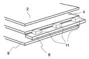
本実施例の照明装置を図面に基づいて説明する。図2は、本実施例の照明装置の概要を模式的に示す外観図である。発光ダイオードパッケージ11からの光が導光体4に入射するように構成され、導光体4の出光面から出た光が第二色変換体2に入射するように構成されている。また、導光体4の出光面の反対側には反射板9が配置されている。ここで、発光ダイオードパッケージ11は赤色蛍光体粒子が分散された樹脂で青色LED素子をポッティングした構成である。この赤色蛍光体粒子を含んだ樹脂が第一色変換体に相当している。また、照射面積に応じた個数の発光ダイオードパッケージ11が回路基板8に実装されている。ここで、導光体4の材料としてはポリカーボネートやアクリル等が例示できる。 The illumination device of the present embodiment will be described with reference to the drawings. FIG. 2 is an external view schematically showing an outline of the illumination device of the present embodiment. The light from the light emitting
このような構成によれば、青色LED素子が発光した光(青色光)は、その一部が赤色に変換され、残りは青色のまま導光体4に入射される。すなわち、発光ダイオードパッケージ11は450nm〜480nmと600nm〜680nmの2つの波長をピークとするスペクトルを有する光(紫光)を出光する。そして、この紫光が導光体4に入射されることになる。導光体4に入射した紫光は、導光体4と反射板9の間で反射と屈折を繰り返し、導光体4の出光面から均一に出射されて、緑色蛍光体粒子を含んだ第二色変換体に届く。第二色変換体に入射した光のうち、一部の光はそのまま(青色光と赤色光のまま)通過し、一部の光は緑色蛍光体粒子で緑色光に変換されて通過する。このとき、緑色蛍光体粒子に届いた赤色成分の光の多くは反射することになる。このように、通過した紫色光と緑色光が混色して白色光が得られることになる。すなわち、導光体4の出光面から出射された光は第二色変換体2を通ることで加法混色し白色光となる。 According to such a configuration, part of the light emitted from the blue LED element (blue light) is converted to red, and the remaining light is incident on the
以下に、本実施例の構成要素である、発光ダイオードパッケージ、第二色変換体、及び反射板について、より詳細に説明する。これらの各構成を単独または組み合わせて図2で示したような照明装置を作製することができる。
(反射板について)
従来の照明装置には、透明フィルムに銀やアルミニウム層を設けた構成の反射板9を用いていた。しかしながら、銀は青色光を吸収する性質があり、またアルミニウムは反射特性が高くないため、本実施例の反射板としてこれを使用すると、結果的に輝度の低下を招く。そのため、可視光範囲において高い反射率を有する反射シートを用いることが好ましい。例えば、白PETフィルム、または、青色成分の反射率の高いポリエステル系樹脂を用いた多層膜フィルムの使用が好ましい。これにより、反射時の損失が小さく、光源を有効活用し画面輝度の大幅な向上が可能になる。この用途に適した市販品には、バックライトの導光板下反射シート用に開発された住友3M社製のESR反射フィルムがある。
(発光ダイオードパッケージについて)
図3は発光ダイオードパッケージ11の構成を模式的に示す断面図である。図示するように、発光ダイオードパッケージ11は青色LED素子10を赤色蛍光体粒子5が分散された樹脂16でポッティングした構成である。青色LED素子10を駆動するための電極端子13と第二電極端子14が回路基板8上に形成されている。InGaN系やGaN系の青色LED素子10が導電性ペーストによって導電性台座12に電気的に接合されている。この導電性台座12は青色LED素子10と電極端子13との電気的接合性を向上させたり、熱伝導性を向上させたり、回路基板8からの高さを調節したりするために用いられている。これらの条件が満足されている環境では必ずしも必要ではない。青色LED素子10には図示されていない電流注入用の二つの電極が形成されており、一方の電極が導電性台座12を介して電極端子13と電気的に接合され、他方の電極はワイヤー15で第二電極端子14と電気的に接合されている。導電性台座11を用いない場合には、両電極ともにワイヤー15を用いてそれぞれの電極端子に電気的に接合すればよい。このワイヤー15には、通常のワイヤーボンディングで用いられる金ワイヤーなどを用いることができる。回路基板8には、導通部である電極端子を除いて絶縁膜等の保護膜が設けられている。回路基板8としてフレキシブルプリント基板やガラスエポキシ基板を用いることができる。Hereinafter, the light-emitting diode package, the second color converter, and the reflector, which are components of the present embodiment, will be described in more detail. Each of these components can be used alone or in combination to produce the lighting device as shown in FIG.
(About reflector)
In the conventional lighting device, a reflector 9 having a transparent film provided with a silver or aluminum layer was used. However, silver has a property of absorbing blue light, and aluminum does not have high reflection characteristics. Therefore, when this is used as a reflection plate of this embodiment, luminance is lowered as a result. Therefore, it is preferable to use a reflection sheet having a high reflectance in the visible light range. For example, it is preferable to use a white PET film or a multilayer film using a polyester resin having a high blue component reflectance. Thereby, the loss at the time of reflection is small, and the luminance of the screen can be greatly improved by effectively using the light source. A commercially available product suitable for this application is an ESR reflective film manufactured by Sumitomo 3M, which was developed for a reflective sheet under a light guide plate of a backlight.
(About light emitting diode package)
FIG. 3 is a cross-sectional view schematically showing the configuration of the light emitting
青色LED素子10と導電性台座12の全て、及び、ワイヤー15の一部または全部には、透光性の樹脂16で被覆されており、その樹脂16の中には赤色蛍光体粒子8が所定の濃度で混合されている。樹脂には、水分を通し難い材料(以下、非通水性材料と称す)を用いることが望ましい。具体的には、シリコン樹脂、シクロオレフィン系樹脂、フッ素系樹脂などの高分子材料を用いることができる。これらの樹脂からいずれかを選択してもよいし、複数の樹脂によるハイブリッドを用いても良い。非通水性材料は、必ずしも透明である必要はなく、透光性があれば良いので、エポキシ系の材料も広く使われている。 All of the
赤色蛍光体粒子5としては、カルコゲナイド化合物の蛍光体微粒子を用いることができる。あるいは、窒化物と希土類ドーパントからなる蛍光体材料や、硫化物と希土類ドーパントからなる蛍光体材料が適している。特に、CaSやSrS等の硫化物と希土類ドーパントとからなる蛍光材料や、窒化物と希土類ドーパントとからなる蛍光材料は、光変換効率が高い。また、赤色蛍光体粒子を非通水性材料でコーティングするとダイオードパッケージの信頼性が向上する。非通水性材料として、SiO2、シリコン樹脂、シクロオレフィン系樹脂、フッ素系樹脂、または、エポキシ系樹脂を用いることができる。特に、硫化物蛍光体の場合、水分と反応して硫化水素を発生することがあるので、LED内部の反射膜が化学反応を起こして、輝度特性が著しく落ちることになる。そのため、硫化物蛍光体を使用する際は、蛍光体粒子そのものを透明な非通水性材料で被覆する必要がある。窒化物蛍光体を使用する場合にはコーティング(非通水性材料による被覆)はなくてもよい。As the
図3に示したように、赤色蛍光体粒子5を所定の割合で樹脂16に混合して青色LED素子10を被覆することによって、InGaN系やGaN系の青色LED素子10からの青色光とこの青色光が波長変換されて生じた赤色光とが加法混色されて目的の色度を持った発光色を得ることが可能となる。この発光色による色再現範囲は、赤色蛍光体粒子5の混合濃度や、各々の蛍光体粒子の平均粒径、および照射する青色光の強度を調節することによって任意に制御することが可能となる。例えば、赤色蛍光体粒子5の混合濃度を、樹脂16の厚みが60〜70μmの時、重量濃度50%程度とするとx=0.35y=0.18近辺の色度座標の光(紫光)が得られる。このとき、青色光の強度を上げるとxy共に小さくなり、下げるとxyともに大きくなる傾向にある。ただし、せいぜい±0.02程度の変化であり、与える影響は小さい。混合濃度が高いため、更にシリカ等の透明ビーズを分散して樹脂16に混入させると、蛍光体粒子の分散性が上がり、発光効率が上昇する。
(第二色変換体について)
次に、緑色蛍光体粒子を含んだ第二色変換体の構成について、いくつか例示する。As shown in FIG. 3, the
(About the second color converter)
Next, some examples of the configuration of the second color converter including the green phosphor particles will be described.
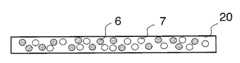
図4は、樹脂20に緑色蛍光体粒子6と透明ビーズ7を分散させて形成された色変換体である。このように、第二色変換体に透明ビーズを分散すると、赤色成分の透過率が上がるため、輝度が上昇するという効果がある。 FIG. 4 shows a color converter formed by dispersing
この理由を簡単に説明する。導光体から第二色変換体に入射した赤と青の混色光は、第二色変換体の緑色蛍光体粒子6にぶつかると、青色成分の一部は励起光となり緑色成分として出光する。しかし、赤色成分のうち緑色蛍光体粒子6に届いた光の大部分はこの緑色蛍光体粒子6で反射されるか界面で吸収される。この反射光は、さらに反射板9や周囲の蛍光体粒子で反射するというように反射を繰り返すことになる。もちろん、反射した赤色成分には結果的に樹脂20を透過するものも存在している。このように、緑色蛍光体粒子6に届いた赤色光の多くは減衰し、一部分の赤色光が出光することになる。そして、上述したように、樹脂20に透明ビーズ7のような可視光透過率の高い物質を緑色蛍光体粒子6と混在させると、緑色蛍光体粒子6のみが集中して存在する領域が確率的になくなり、透明ビーズ7を通過して出光する赤色成分が確保されることになるため、赤色成分が出光する確率が高くなり、結果的に輝度の上昇につながる。透明ビーズ7として、アクリルやシリカなどの透明な微粒子が適している。 The reason for this will be briefly described. When the mixed color light of red and blue incident on the second color converter from the light guide collides with the
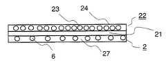
図5は、第二色変換体2と拡散層22を備えた構成を模式的に示す断面図である。第二色変換体2は透明樹脂27に緑色蛍光体粒子6が分散された構成である。そして、拡散層22が第二色変換体2よりも観察者側に設けられている。図5の構成では、ペットやポリカーボネートやアクリルやゼオノア等の透明基材21を挟んで拡散層22と透明樹脂27が積層されている。透明基材には非通水性な透明基材が好ましい。また、拡散層22は樹脂24に透明拡散ビーズ23が分散された構成である。アクリルやシリカ等の透明拡散ビーズ23が分散された樹脂24を透明基材21の上面に塗布して硬化させ、一方、緑色蛍光体粒子6が分散された透明樹脂27を透明基材21の下面に塗布して硬化させることにより作製できる。透明拡散ビーズ23により出射光が拡散するため、面輝度の均一性の高い照明装置の実現が可能となる。ここで、透明拡散ビーズ23として、前述の透明ビーズ7と同じ材料を用いてもよい。 FIG. 5 is a cross-sectional view schematically showing a configuration including the
図6は、透明フィルムに非通水処理を施した非通水性透明基材25で緑色蛍光体粒子6が分散された透明樹脂27を挟んだ構成を模式的に示す断面図である。透明フィルムとして、PETやポリカーボネートやアクリル等の透明フィルムを用い、非通水処理として、SnO2やSiO2等のバリア層を透明フィルムに施している。バリア層の層構成は単層とは限らず、複数の層を形成するほうが非通水性面での効果は高い。非通水性透明基材25に、あらかじめ熱可塑性等の透明接着層26を塗布しておき、その上に緑色蛍光体粒子6が分散された樹脂27を塗布し、硬化させる。透明接着層26は粘着層であってもかまわない。緑色蛍光体粒子6を含んだ透明樹脂27が端面から外部の空気層と触れることがないように、透明樹脂27の端面を覆うように、透明接着層26をさらに設ける必要がある。そのため、塗布の方法はスクリーン印刷等のマスク印刷方が好ましい。その上に別の非通水性透明基板25をラミネートする。このような構成により、蛍光体粒子を効果的に水分から防御することが可能になる。そのため、第二色変換体の劣化を防ぐこととなり、信頼性が向上する。更に、樹脂24に5〜30μm程度のシリカやアクリルの透明ビーズ23を分散し、この樹脂24を非通水性透明基材25の片面に設けた。この樹脂24がない場合には、非通水性透明基板と空気の屈折率差により透明樹脂からの光の一部は界面で反射してしまう。透明ビーズ23が分散された樹脂24を設けることにより、この反射を防止でき、結果的に光の利用効率が上昇する。また、光の拡散性が向上するため、広視野角化や面内ムラ隠し等の効果もある。FIG. 6 is a cross-sectional view schematically showing a configuration in which a
ここでは、緑色蛍光体粒子6を樹脂に分散させたが、透明基材21内に練りこんだり、導光体4に塗布又は練りこみを行ったり、被照明体であるLCDパネル等の表示素子の光入光面に塗布しても同様の効果が得られる。 Here, the
緑色蛍光体粒子6の材料としては、II族金属チオガレートと希土類ドーパントとからなる蛍光材料や、酸化物と希土類ドーパントからなる蛍光材料や、Sr−SIONと希土類ドーパントからなる蛍光材料等を用いることができる。すなわち、YAG蛍光体以上の輝度効率を有するものが適している。また、緑色蛍光体粒子6をSiO2等の透明非通水材料で被覆すると、更に高い信頼性を得ることができる。As the material of the
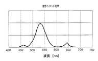
緑色蛍光体粒子の添加量を0.2mg/cm2程度とし、図3で示した構成の上述の発光ダイオードパッケージ11と組み合わせることで、x=0.31、y=0.31付近の白色光を得ることができる。図7にニ波長型擬似白色LEDを発光光源として用いた従来の照明装置の発光スペクトルを示す。600nm以上が赤色成分の波長領域であるが、青色と黄色と比較して著しく赤色成分が少ない。一方、上述した構成の照明装置の発光スペクトルを図8に示す。600nm以上の赤色発光領域が図7と比較して非常に高いことがわかる。White light around x = 0.31 and y = 0.31 is obtained by adding the amount of green phosphor particles to about 0.2 mg / cm2 and combining with the above-described light emitting
また、照明装置で照明される液晶表示パネルには、様々な種類のカラーフィルタや液晶材料が用いられている。厳密には、これに応じて異なる色調の照明装置を準備する必要がある。しかしながら、何種類もの発光ダイオードパッケージ11を準備することは、大量生産によるコストダウンや在庫リスクの観点から好ましくない。そこで、第二色変換体2に緑色蛍光体粒子6だけでなく、赤色蛍光体粒子を微量に混合添加して、色調を赤色側にシフトすることを可能にさせる。あらかじめ紫色発光の発光ダイオードパッケージ11の色調を青色側にシフトさせておけば、第二色変換体2の色調補正を行うだけで、あらゆる種類のLCDパネルへの色調対応が容易となる。このとき、第二色変換体への赤色蛍光体粒子の混合量は、例えば、赤色蛍光体粒子がCaSと希土類ドーパントからなる蛍光材料で、緑色蛍光体粒子6がII族金属チオガレートと希土類ドーパントとからなる蛍光材料の場合、緑色蛍光体粒子に対して重量比約30%とすることで、xy色度座標上でおおよそ次の式(式1、式2)で表すシフト量となることを確認した。 Various types of color filters and liquid crystal materials are used for the liquid crystal display panel illuminated by the illumination device. Strictly speaking, it is necessary to prepare lighting devices of different colors according to this. However, it is not preferable to prepare several types of light emitting diode packages 11 from the viewpoint of cost reduction and inventory risk due to mass production. Therefore, not only the
Δx=+0.04 (式1)
Δy=−0.02 (式2)
従って、緑色蛍光体粒子に対して0〜30%の範囲内で赤色蛍光体粒子の重量比を制御することで、現在市場に流通しているLCDパネルの大半に対応可能である。Δx = + 0.04 (Formula 1)
Δy = −0.02 (Formula 2)
Therefore, by controlling the weight ratio of the red phosphor particles within a range of 0 to 30% with respect to the green phosphor particles, it is possible to cope with most LCD panels currently on the market.
また、蛍光材料によっては、封止樹脂との分散性等の相性の問題から、発光ダイオードパッケージ11に微量添加する赤色蛍光体粒子5をそのまま第二色変換体に添加することが困難な場合がある。そのような場合、必ずしも赤色蛍光体粒子5と同様の組成である必要はない。例えば、発光ダイオードパッケージ11に添加する赤色蛍光体粒子5として窒化物と希土類ドーパントとからなる蛍光材料を使用し、第二色変換体に微量添加する赤色蛍光体として、CaSやSrSと希土類ドーパントからなる蛍光材料を使用することも可能である。特にSrSは発光波長ピークを600nm近辺に有しており、赤色というよりも橙色であるため、視感度特性が良く、高輝度化が求められるLCDパネル用としては適しているといえる。また、微量添加する蛍光材料として、YAG蛍光体のような黄色発光蛍光材料を用いることで、黄色側への色シフト制御も可能となる。 Further, depending on the fluorescent material, it may be difficult to add the
図9は、本実施例の照明装置の全体構成を模式的に示す断面図である。実施例1の照明装置の構成とは、反射板がなく、代わりに導光体4の裏面にプリズムが設けられているという点で異なっている。図3で示した構成の発光ダイオードパッケージ11を点灯し、導光体4に入光させる。入光した光は、最適な角度と高さに設計されたプリズム17により断面図上部の出光面から均一に発光する。そして、第二色変換体2を通ることによって、青色光の一部が変換されて緑色光となり、青色光と赤色光と緑色光の三色の加法混色による白色光を得ることができる。導光体4や発光ダイオードパッケージ11はフレーム18内に収納されている。その他の構成については、実施例1で説明したそれぞれの構成要素を適宜、用いることができる。 FIG. 9 is a cross-sectional view schematically showing the overall configuration of the lighting apparatus of the present embodiment. The configuration of the illuminating device of Example 1 is different in that there is no reflector and a prism is provided on the back surface of the
次に、非自発光型の表示素子として液晶表示パネルを用いた液晶表示装置を説明する。図10は、液晶表示装置の断面構成を示す模式図である。図1で示した照明装置の発光面上に液晶表示パネル30が配置されている。ここでは図1と重複する説明は省略する。液晶表示パネル30がカラーフィルタを備えており、カラー表示が可能な表示装置の場合には、光源のスペクトルにあわせてカラーフィルタの着色部にチューニングを施す必要がある。特に、緑色着色部の調整が重要である。 Next, a liquid crystal display device using a liquid crystal display panel as a non-self-luminous display element will be described. FIG. 10 is a schematic diagram illustrating a cross-sectional configuration of the liquid crystal display device. A liquid
従来のようにYAG蛍光体を用いた疑似白色LEDを光源として用いた場合、液晶表示パネルに設けられるカラーフィルタは疑似白色LEDの発光スペクトル(図7)にあわせて作製する必要があり、緑色は黄色と青色の加法混色によって作っていた。すなわち、カラーフィルタの緑着色層には、黄色側の波長域も青色側の波長域も透過する特性が必要であった。図11に、従来のYAG蛍光体を用いた疑似白色LED光源とそれに適合したカラーフィルタを用いた場合に、カラーフィルタの緑着色層を透過する光の透過光特性を示す。これと同じ緑着色層と本発明の照明装置を組み合わせた場合に、緑着色層を透過する光の透過光特性を図12に示す。図12に示すとおり、このような組み合わせでは、高純度の緑色に青色光が混ざることとなり、結果として色純度の低下を招く。本発明の照明装置に組み合わせる液晶表示パネルの緑着色層には、470nm以下の青色光および、600nm以上の赤色光の透過率を極力下げた特性を備えることが好ましい。このような特性の緑着色層を持つカラーフィルタを使用すると、非常に色純度の高い液晶表示装置が実現できる。図13はこの構成により得られるスペクトル特性である。青色光及び赤色光の透過率は低ければ低いほど色純度を上げる効果が高いが、目安としては535nm近辺の緑色光の透過率の20%以下に抑えることが望ましい。 When a pseudo white LED using a YAG phosphor is used as a light source as in the prior art, the color filter provided on the liquid crystal display panel must be prepared according to the emission spectrum of the pseudo white LED (FIG. 7). It was made by an additive color mixture of yellow and blue. That is, the green colored layer of the color filter needs to have a characteristic of transmitting both the yellow wavelength region and the blue wavelength region. FIG. 11 shows the transmitted light characteristics of light transmitted through the green colored layer of the color filter when a pseudo white LED light source using a conventional YAG phosphor and a color filter adapted thereto are used. FIG. 12 shows the transmitted light characteristics of light transmitted through the green colored layer when the same green colored layer and the illumination device of the present invention are combined. As shown in FIG. 12, in such a combination, blue light is mixed with high purity green, resulting in a decrease in color purity. The green colored layer of the liquid crystal display panel to be combined with the lighting device of the present invention preferably has a characteristic that the transmittance of blue light of 470 nm or less and red light of 600 nm or more is reduced as much as possible. When a color filter having a green colored layer having such characteristics is used, a liquid crystal display device with very high color purity can be realized. FIG. 13 shows spectral characteristics obtained by this configuration. The lower the blue light and red light transmittances, the higher the effect of increasing the color purity. However, as a guideline, it is desirable to suppress the transmittance to 20% or less of the green light transmittance around 535 nm.
1 第一の色変換体
2 第二の色変換体
3 青色発光素子
4 導光体
5 赤色蛍光体粒子
6 緑色蛍光体粒子
7 透明ビーズ
8 回路基板
9 反射板
10 青色LED素子
11 発光ダイオードパッケージ
12 導電性台座
13 電極端子
14 電極端子
15 ワイヤー
16 樹脂
17 プリズム
18 フレーム
20 樹脂
21 透明基材
22 拡散層
23 透明拡散ビーズ
24 樹脂
25 非通水性透明基材
26 透明接着層
27 透明樹脂
30 液晶表示パネルDESCRIPTION OF
Claims (22)
Translated fromJapanese前記第二色変換体には青色で光を励起する第三の蛍光体が含まれ、前記第三の蛍光体は前記緑色蛍光体に対する重量比で30%以下の割合で混合していることを特徴とする請求項1に記載の照明装置。The first color converter contains a red phosphor that converts red light with blue excitation, and the second color converter contains a green phosphor that converts green light with blue excitation,
The second color converter includes a third phosphor that excites light in blue, and the third phosphor is mixed at a ratio of 30% or less by weight with respect to the green phosphor. The lighting device according to claim 1, wherein
青色励起で赤色光に変換する第一色変換体と、青色励起で緑色光に変換する第二色変換体を備えるとともに、前記第二色変換体は、前記第一色変換体と前記表示素子の間の光路中に、前記第一色変換体とは分離して設けられたことを特徴とする表示装置。A display device that illuminates a non-self-luminous display element using light emission of a blue light-emitting element,
A first color converter that converts red light by blue excitation and a second color converter that converts green light by blue excitation, and the second color converter includes the first color converter and the display element A display device characterized in that it is provided separately from the first color converter in the optical path between the two.
前記第二色変換体には青色光で励起して光を発光する第三の蛍光体が含まれ、前記第三の蛍光体は前記緑色蛍光体に対する重量比で30%以下の割合で混合していることを特徴とする請求項16〜18のいずれか一項に記載の表示装置。The first color converter contains a red phosphor that converts red light with blue excitation, and the second color converter contains a green phosphor that converts green light with blue excitation,
The second color converter includes a third phosphor that emits light when excited by blue light, and the third phosphor is mixed at a ratio of 30% or less by weight with respect to the green phosphor. The display device according to claim 16, wherein the display device is a display device.
Priority Applications (4)
| Application Number | Priority Date | Filing Date | Title |
|---|---|---|---|
| JP2006200347AJP4898332B2 (en) | 2005-09-15 | 2006-07-24 | Display device |
| TW095132022ATW200722867A (en) | 2005-09-15 | 2006-08-30 | Illumination device and display device provided with the same |
| US11/521,044US7661841B2 (en) | 2005-09-15 | 2006-09-14 | Illumination device and display device provided with the same |
| CN2006101539556ACN1932370B (en) | 2005-09-15 | 2006-09-15 | Illumination device and display device provided with the same |
Applications Claiming Priority (7)
| Application Number | Priority Date | Filing Date | Title |
|---|---|---|---|
| JP2005268517 | 2005-09-15 | ||
| JP2005268517 | 2005-09-15 | ||
| JP2005355736 | 2005-12-09 | ||
| JP2005355736 | 2005-12-09 | ||
| JP2006029856 | 2006-02-07 | ||
| JP2006029856 | 2006-02-07 | ||
| JP2006200347AJP4898332B2 (en) | 2005-09-15 | 2006-07-24 | Display device |
Publications (3)
| Publication Number | Publication Date |
|---|---|
| JP2007243135Atrue JP2007243135A (en) | 2007-09-20 |
| JP2007243135A5 JP2007243135A5 (en) | 2009-05-07 |
| JP4898332B2 JP4898332B2 (en) | 2012-03-14 |
Family
ID=37854395
Family Applications (1)
| Application Number | Title | Priority Date | Filing Date |
|---|---|---|---|
| JP2006200347AExpired - Fee RelatedJP4898332B2 (en) | 2005-09-15 | 2006-07-24 | Display device |
Country Status (4)
| Country | Link |
|---|---|
| US (1) | US7661841B2 (en) |
| JP (1) | JP4898332B2 (en) |
| CN (1) | CN1932370B (en) |
| TW (1) | TW200722867A (en) |
Cited By (8)
| Publication number | Priority date | Publication date | Assignee | Title |
|---|---|---|---|---|
| WO2009131092A1 (en)* | 2008-04-25 | 2009-10-29 | ソニー株式会社 | Light-emitting device, display device, and color conversion sheet |
| JP2010192446A (en)* | 2009-02-17 | 2010-09-02 | Lg Innotek Co Ltd | Light unit and display having the same |
| JP2011013567A (en)* | 2009-07-03 | 2011-01-20 | Sony Corp | Color conversion member and display device |
| JP2012501090A (en)* | 2008-08-29 | 2012-01-12 | フィリップス ルミレッズ ライティング カンパニー リミテッド ライアビリティ カンパニー | Light source including wavelength conversion semiconductor light emitting device and filter |
| TWI461793B (en)* | 2010-07-09 | 2014-11-21 | Lg伊諾特股份有限公司 | Display device |
| KR20170052729A (en)* | 2015-11-03 | 2017-05-15 | 삼성디스플레이 주식회사 | Display device |
| US10490711B2 (en) | 2014-10-07 | 2019-11-26 | Nichia Corporation | Light emitting device |
| KR20200007052A (en)* | 2017-05-23 | 2020-01-21 | 인터매틱스 코포레이션 | Color Liquid Crystal Display and Display Backlight |
Families Citing this family (49)
| Publication number | Priority date | Publication date | Assignee | Title |
|---|---|---|---|---|
| WO2006131924A2 (en) | 2005-06-07 | 2006-12-14 | Oree, Advanced Illumination Solutions Inc. | Illumination apparatus |
| US8272758B2 (en)* | 2005-06-07 | 2012-09-25 | Oree, Inc. | Illumination apparatus and methods of forming the same |
| US8215815B2 (en)* | 2005-06-07 | 2012-07-10 | Oree, Inc. | Illumination apparatus and methods of forming the same |
| KR100900620B1 (en)* | 2007-02-20 | 2009-06-02 | 삼성전기주식회사 | White light emitting device |
| KR100874163B1 (en)* | 2007-04-03 | 2008-12-17 | 유니나 | LCD module with direct-view color light emitting frame |
| WO2008146290A2 (en)* | 2007-05-29 | 2008-12-04 | Oree, Advanced Illumination Solutions Inc. | Method and device for providing circumferential illumination |
| CN101785121B (en)* | 2007-08-30 | 2013-04-03 | 日亚化学工业株式会社 | Light emitting device |
| JP5211667B2 (en)* | 2007-12-07 | 2013-06-12 | ソニー株式会社 | Lighting device and display device |
| US7907804B2 (en)* | 2007-12-19 | 2011-03-15 | Oree, Inc. | Elimination of stitch artifacts in a planar illumination area |
| US8182128B2 (en)* | 2007-12-19 | 2012-05-22 | Oree, Inc. | Planar white illumination apparatus |
| CN101270862B (en)* | 2008-02-20 | 2012-06-27 | 张丽红 | Blue-ray LED for meanwhile implementing blue-ray panel display and white light illumination |
| US20090225566A1 (en)* | 2008-03-05 | 2009-09-10 | Micha Zimmermann | Illumination apparatus and methods of forming the same |
| US8297786B2 (en) | 2008-07-10 | 2012-10-30 | Oree, Inc. | Slim waveguide coupling apparatus and method |
| US8301002B2 (en)* | 2008-07-10 | 2012-10-30 | Oree, Inc. | Slim waveguide coupling apparatus and method |
| US8294848B2 (en)* | 2008-10-01 | 2012-10-23 | Samsung Display Co., Ltd. | Liquid crystal display having light diffusion layer |
| US20100098377A1 (en)* | 2008-10-16 | 2010-04-22 | Noam Meir | Light confinement using diffusers |
| JP4772105B2 (en)* | 2008-12-10 | 2011-09-14 | シャープ株式会社 | Semiconductor light emitting device and image display device using the same |
| JP5717949B2 (en)* | 2009-01-26 | 2015-05-13 | デクセリアルズ株式会社 | Optical member and display device |
| US7995911B2 (en)* | 2009-01-26 | 2011-08-09 | Koninklijke Philips Electronics N.V. | Matching led flash to camera's ambient light compensation algorithm |
| US20100208469A1 (en)* | 2009-02-10 | 2010-08-19 | Yosi Shani | Illumination surfaces with reduced linear artifacts |
| US8624527B1 (en) | 2009-03-27 | 2014-01-07 | Oree, Inc. | Independently controllable illumination device |
| US20100320904A1 (en)* | 2009-05-13 | 2010-12-23 | Oree Inc. | LED-Based Replacement Lamps for Incandescent Fixtures |
| US8540410B2 (en) | 2009-06-08 | 2013-09-24 | Leon Eisen | Submerged planar illumination device |
| WO2010150202A2 (en) | 2009-06-24 | 2010-12-29 | Oree, Advanced Illumination Solutions Inc. | Illumination apparatus with high conversion efficiency and methods of forming the same |
| IT1401974B1 (en)* | 2010-09-28 | 2013-08-28 | Università Degli Studi Di Milano Bicocca | LIGHTING DEVICE |
| KR101210101B1 (en)* | 2010-11-23 | 2012-12-07 | 엘지이노텍 주식회사 | Display device |
| DE102011078402A1 (en) | 2011-06-30 | 2013-01-03 | Osram Ag | Conversion element and light-emitting diode with such a conversion element |
| US8591072B2 (en) | 2011-11-16 | 2013-11-26 | Oree, Inc. | Illumination apparatus confining light by total internal reflection and methods of forming the same |
| WO2014006501A1 (en) | 2012-07-03 | 2014-01-09 | Yosi Shani | Planar remote phosphor illumination apparatus |
| DE102012109650A1 (en)* | 2012-10-10 | 2014-04-10 | Osram Opto Semiconductors Gmbh | Ceramic conversion element, optoelectronic semiconductor element and method for producing a ceramic conversion element |
| DE102013222430A1 (en) | 2013-11-05 | 2015-05-07 | Osram Gmbh | An illumination apparatus and method for generating light by means of a wavelength conversion arrangement and a band stop filter and method for providing a band stop filter |
| WO2015170814A1 (en)* | 2014-05-09 | 2015-11-12 | Lg Electronics Inc. | Apparatus of light source for display and apparatus of display using the same |
| EP3045963B1 (en)* | 2015-01-13 | 2018-04-04 | Samsung Display Co., Ltd. | Display device |
| US20160349431A1 (en)* | 2015-05-29 | 2016-12-01 | Hon Hai Precision Industry Co., Ltd. | Backlight module and liquid crystal display device |
| US10918747B2 (en) | 2015-07-30 | 2021-02-16 | Vital Vio, Inc. | Disinfecting lighting device |
| US20180185533A1 (en) | 2016-12-29 | 2018-07-05 | Vital Vio, Inc. | Control systems for disinfecting light systems and methods of regulating operations of disinfecting light systems |
| CN206848650U (en) | 2017-05-04 | 2018-01-05 | 深圳市华星光电技术有限公司 | A kind of optical film assembly, backlight module and display device |
| CN206848648U (en)* | 2017-05-04 | 2018-01-05 | 深圳市华星光电技术有限公司 | A kind of backlight module and display device |
| CN206848649U (en)* | 2017-05-04 | 2018-01-05 | 深圳市华星光电技术有限公司 | A kind of optical film, backlight module and display device for backlight module |
| KR20190086611A (en) | 2018-01-12 | 2019-07-23 | 삼성디스플레이 주식회사 | Backlight unit and display apparatus incvluding the same |
| US10413626B1 (en)* | 2018-03-29 | 2019-09-17 | Vital Vio, Inc. | Multiple light emitter for inactivating microorganisms |
| US11506360B2 (en) | 2018-10-22 | 2022-11-22 | Sharp Kabushiki Kaisha | Optical element and optical device |
| US12194168B2 (en) | 2018-12-19 | 2025-01-14 | Vyv, Inc. | Lighting and dissipation device |
| CN110454733A (en)* | 2019-08-05 | 2019-11-15 | 陈军 | Photovoltaic rare earth energy storing self-luminous road guiding lamp |
| WO2021030748A1 (en) | 2019-08-15 | 2021-02-18 | Vital Vio, Inc. | Devices configured to disinfect interiors |
| US11878084B2 (en) | 2019-09-20 | 2024-01-23 | Vyv, Inc. | Disinfecting light emitting subcomponent |
| TWI783282B (en)* | 2020-10-23 | 2022-11-11 | 欣興電子股份有限公司 | Rearview mirror with display function |
| CN114506276A (en)* | 2020-10-23 | 2022-05-17 | 欣兴电子股份有限公司 | Rear view mirror with display function |
| CN119050244B (en)* | 2024-10-31 | 2025-03-07 | 华引芯(张家港)半导体有限公司 | Quantum dot Mini LED packaging device and display device |
Citations (5)
| Publication number | Priority date | Publication date | Assignee | Title |
|---|---|---|---|---|
| JP2003014748A (en)* | 2001-06-28 | 2003-01-15 | Fuji Photo Film Co Ltd | Composite material sheet for analyzing organism-related substance |
| JP2003100126A (en)* | 2001-09-20 | 2003-04-04 | Citizen Electronics Co Ltd | Chromaticity correction by light guide plate |
| JP2004164977A (en)* | 2002-11-12 | 2004-06-10 | Nichia Chem Ind Ltd | Light emitting device using phosphor sheet |
| JP2004186278A (en)* | 2002-11-29 | 2004-07-02 | Toyoda Gosei Co Ltd | Light emitting device and light emitting method |
| JP2005244226A (en)* | 2004-02-23 | 2005-09-08 | Lumileds Lighting Us Llc | Wavelength conversion type semiconductor light emitting device |
Family Cites Families (10)
| Publication number | Priority date | Publication date | Assignee | Title |
|---|---|---|---|---|
| JPH11109326A (en)* | 1997-09-30 | 1999-04-23 | Kawaguchiko Seimitsu Kk | Reflection type liquid crystal panel |
| KR100730433B1 (en)* | 1998-10-28 | 2007-06-19 | 다이니폰 인사츠 가부시키가이샤 | LCD Display |
| EP1104799A1 (en)* | 1999-11-30 | 2001-06-06 | Patent-Treuhand-Gesellschaft für elektrische Glühlampen mbH | Red emitting luminescent material |
| US6806856B2 (en)* | 2001-08-09 | 2004-10-19 | Microsoft Corporation | Reflective displays with color filter cross-talk compensation |
| US6806642B2 (en)* | 2001-09-04 | 2004-10-19 | Durel Corporation | Light source with cascading dyes and BEF |
| TW563261B (en)* | 2002-06-07 | 2003-11-21 | Solidlite Corp | A method and of manufacture for tri-color white LED |
| US6637905B1 (en)* | 2002-09-26 | 2003-10-28 | Agilent Technologies, Inc. | Method and system for providing backlighting utilizing a luminescent impregnated material |
| US7204630B2 (en)* | 2004-06-30 | 2007-04-17 | 3M Innovative Properties Company | Phosphor based illumination system having a plurality of light guides and an interference reflector |
| US8324640B2 (en)* | 2004-07-02 | 2012-12-04 | GE Lighting Solutions, LLC | LED-based edge lit illumination system |
| JP2008010556A (en)* | 2006-06-28 | 2008-01-17 | Stanley Electric Co Ltd | LED light source device and LED backlight using the same |
- 2006
- 2006-07-24JPJP2006200347Apatent/JP4898332B2/ennot_activeExpired - Fee Related
- 2006-08-30TWTW095132022Apatent/TW200722867A/enunknown
- 2006-09-14USUS11/521,044patent/US7661841B2/enactiveActive
- 2006-09-15CNCN2006101539556Apatent/CN1932370B/ennot_activeExpired - Fee Related
Patent Citations (5)
| Publication number | Priority date | Publication date | Assignee | Title |
|---|---|---|---|---|
| JP2003014748A (en)* | 2001-06-28 | 2003-01-15 | Fuji Photo Film Co Ltd | Composite material sheet for analyzing organism-related substance |
| JP2003100126A (en)* | 2001-09-20 | 2003-04-04 | Citizen Electronics Co Ltd | Chromaticity correction by light guide plate |
| JP2004164977A (en)* | 2002-11-12 | 2004-06-10 | Nichia Chem Ind Ltd | Light emitting device using phosphor sheet |
| JP2004186278A (en)* | 2002-11-29 | 2004-07-02 | Toyoda Gosei Co Ltd | Light emitting device and light emitting method |
| JP2005244226A (en)* | 2004-02-23 | 2005-09-08 | Lumileds Lighting Us Llc | Wavelength conversion type semiconductor light emitting device |
Cited By (16)
| Publication number | Priority date | Publication date | Assignee | Title |
|---|---|---|---|---|
| JP2009283441A (en)* | 2008-04-25 | 2009-12-03 | Sony Corp | Light-emitting device, display device, and color-converting sheet |
| US8514350B2 (en) | 2008-04-25 | 2013-08-20 | Sony Corporation | Light emitting device, display device, and color conversion sheet |
| WO2009131092A1 (en)* | 2008-04-25 | 2009-10-29 | ソニー株式会社 | Light-emitting device, display device, and color conversion sheet |
| JP2012501090A (en)* | 2008-08-29 | 2012-01-12 | フィリップス ルミレッズ ライティング カンパニー リミテッド ライアビリティ カンパニー | Light source including wavelength conversion semiconductor light emitting device and filter |
| JP2010192446A (en)* | 2009-02-17 | 2010-09-02 | Lg Innotek Co Ltd | Light unit and display having the same |
| JP2011013567A (en)* | 2009-07-03 | 2011-01-20 | Sony Corp | Color conversion member and display device |
| TWI461793B (en)* | 2010-07-09 | 2014-11-21 | Lg伊諾特股份有限公司 | Display device |
| US9207380B2 (en) | 2010-07-09 | 2015-12-08 | Lg Innotek Co., Ltd. | Display device |
| US10714664B2 (en) | 2014-10-07 | 2020-07-14 | Nichia Corporation | Light emitting device |
| US10490711B2 (en) | 2014-10-07 | 2019-11-26 | Nichia Corporation | Light emitting device |
| KR20170052729A (en)* | 2015-11-03 | 2017-05-15 | 삼성디스플레이 주식회사 | Display device |
| KR102474116B1 (en)* | 2015-11-03 | 2022-12-06 | 삼성디스플레이 주식회사 | Display device |
| KR20200007052A (en)* | 2017-05-23 | 2020-01-21 | 인터매틱스 코포레이션 | Color Liquid Crystal Display and Display Backlight |
| KR20210109060A (en)* | 2017-05-23 | 2021-09-03 | 인터매틱스 코포레이션 | Color Liquid Crystal Displays and Display Backlights |
| KR102297503B1 (en)* | 2017-05-23 | 2021-09-03 | 인터매틱스 코포레이션 | Color liquid crystal display and display backlight |
| KR102448122B1 (en)* | 2017-05-23 | 2022-09-27 | 인터매틱스 코포레이션 | Color liquid crystal display and display backlight |
Also Published As
| Publication number | Publication date |
|---|---|
| CN1932370B (en) | 2012-03-14 |
| US7661841B2 (en) | 2010-02-16 |
| TW200722867A (en) | 2007-06-16 |
| CN1932370A (en) | 2007-03-21 |
| US20070057626A1 (en) | 2007-03-15 |
| JP4898332B2 (en) | 2012-03-14 |
Similar Documents
| Publication | Publication Date | Title |
|---|---|---|
| JP4898332B2 (en) | Display device | |
| JP4931628B2 (en) | Illumination device and display device including the same | |
| JP6554592B2 (en) | Lighting device, display device, and television receiver | |
| US7859175B2 (en) | Illuminating device, display device and optical film | |
| JP6532179B2 (en) | Lighting device, display device, and television receiver | |
| US8210701B2 (en) | Lighting device and display device having the same | |
| CN100559066C (en) | Phosphor thin film, lighting device and display device using same | |
| JP2009231273A (en) | Illumination device and display device equipped therewith | |
| US20060268537A1 (en) | Phosphor film, lighting device using the same, and display device | |
| KR100958759B1 (en) | Backlight and liquid crystal display using it | |
| JP4976196B2 (en) | Display device and lighting device | |
| US20060284532A1 (en) | Color display unit | |
| JP2006291064A (en) | Phosphor film, device of illumination and displaying device having the same | |
| EP2881783B1 (en) | Display device having a light-emitting diode (LED) package as light source | |
| US10121941B2 (en) | Light source device | |
| CN107851420A (en) | Display device and radiovisor | |
| CN107960115A (en) | Lighting device, display device and television receiving device | |
| JP2008288440A (en) | Integrated display device | |
| JP2008108523A (en) | Lighting system, and display device equipped with it | |
| JP2022152904A (en) | Luminaire and display device | |
| KR20070031814A (en) | Lighting device and display device having same | |
| JP4800669B2 (en) | LIGHTING DEVICE AND DISPLAY DEVICE USING THE SAME | |
| JP3118574U (en) | Liquid crystal panel device with side light source module | |
| CN117348295A (en) | Mini-LED quantum dot backlight source for eliminating bluing edge and display device | |
| JP2017191693A (en) | Surface light-emitting device and image formation device |
Legal Events
| Date | Code | Title | Description |
|---|---|---|---|
| A521 | Request for written amendment filed | Free format text:JAPANESE INTERMEDIATE CODE: A523 Effective date:20090319 | |
| A621 | Written request for application examination | Free format text:JAPANESE INTERMEDIATE CODE: A621 Effective date:20090319 | |
| RD01 | Notification of change of attorney | Free format text:JAPANESE INTERMEDIATE CODE: A7421 Effective date:20091105 | |
| RD01 | Notification of change of attorney | Free format text:JAPANESE INTERMEDIATE CODE: A7421 Effective date:20091113 | |
| A977 | Report on retrieval | Free format text:JAPANESE INTERMEDIATE CODE: A971007 Effective date:20110810 | |
| A131 | Notification of reasons for refusal | Free format text:JAPANESE INTERMEDIATE CODE: A131 Effective date:20110817 | |
| A521 | Request for written amendment filed | Free format text:JAPANESE INTERMEDIATE CODE: A523 Effective date:20111013 | |
| TRDD | Decision of grant or rejection written | ||
| A01 | Written decision to grant a patent or to grant a registration (utility model) | Free format text:JAPANESE INTERMEDIATE CODE: A01 Effective date:20111220 | |
| A01 | Written decision to grant a patent or to grant a registration (utility model) | Free format text:JAPANESE INTERMEDIATE CODE: A01 | |
| A61 | First payment of annual fees (during grant procedure) | Free format text:JAPANESE INTERMEDIATE CODE: A61 Effective date:20111226 | |
| R150 | Certificate of patent or registration of utility model | Ref document number:4898332 Country of ref document:JP Free format text:JAPANESE INTERMEDIATE CODE: R150 | |
| FPAY | Renewal fee payment (event date is renewal date of database) | Free format text:PAYMENT UNTIL: 20150106 Year of fee payment:3 | |
| R250 | Receipt of annual fees | Free format text:JAPANESE INTERMEDIATE CODE: R250 | |
| R250 | Receipt of annual fees | Free format text:JAPANESE INTERMEDIATE CODE: R250 | |
| R250 | Receipt of annual fees | Free format text:JAPANESE INTERMEDIATE CODE: R250 | |
| R250 | Receipt of annual fees | Free format text:JAPANESE INTERMEDIATE CODE: R250 | |
| R250 | Receipt of annual fees | Free format text:JAPANESE INTERMEDIATE CODE: R250 | |
| R250 | Receipt of annual fees | Free format text:JAPANESE INTERMEDIATE CODE: R250 | |
| LAPS | Cancellation because of no payment of annual fees |