JP2007236197A - Power supply - Google Patents
Power supplyDownload PDFInfo
- Publication number
- JP2007236197A JP2007236197AJP2007133912AJP2007133912AJP2007236197AJP 2007236197 AJP2007236197 AJP 2007236197AJP 2007133912 AJP2007133912 AJP 2007133912AJP 2007133912 AJP2007133912 AJP 2007133912AJP 2007236197 AJP2007236197 AJP 2007236197A
- Authority
- JP
- Japan
- Prior art keywords
- fuel cell
- voltage
- reference voltage
- power
- power supply
- Prior art date
- Legal status (The legal status is an assumption and is not a legal conclusion. Google has not performed a legal analysis and makes no representation as to the accuracy of the status listed.)
- Pending
Links
Images


Classifications
- Y—GENERAL TAGGING OF NEW TECHNOLOGICAL DEVELOPMENTS; GENERAL TAGGING OF CROSS-SECTIONAL TECHNOLOGIES SPANNING OVER SEVERAL SECTIONS OF THE IPC; TECHNICAL SUBJECTS COVERED BY FORMER USPC CROSS-REFERENCE ART COLLECTIONS [XRACs] AND DIGESTS
- Y02—TECHNOLOGIES OR APPLICATIONS FOR MITIGATION OR ADAPTATION AGAINST CLIMATE CHANGE
- Y02E—REDUCTION OF GREENHOUSE GAS [GHG] EMISSIONS, RELATED TO ENERGY GENERATION, TRANSMISSION OR DISTRIBUTION
- Y02E60/00—Enabling technologies; Technologies with a potential or indirect contribution to GHG emissions mitigation
- Y02E60/30—Hydrogen technology
- Y02E60/50—Fuel cells
- Y—GENERAL TAGGING OF NEW TECHNOLOGICAL DEVELOPMENTS; GENERAL TAGGING OF CROSS-SECTIONAL TECHNOLOGIES SPANNING OVER SEVERAL SECTIONS OF THE IPC; TECHNICAL SUBJECTS COVERED BY FORMER USPC CROSS-REFERENCE ART COLLECTIONS [XRACs] AND DIGESTS
- Y02—TECHNOLOGIES OR APPLICATIONS FOR MITIGATION OR ADAPTATION AGAINST CLIMATE CHANGE
- Y02T—CLIMATE CHANGE MITIGATION TECHNOLOGIES RELATED TO TRANSPORTATION
- Y02T10/00—Road transport of goods or passengers
- Y02T10/60—Other road transportation technologies with climate change mitigation effect
- Y02T10/72—Electric energy management in electromobility
Landscapes
- Fuel Cell (AREA)
- Electric Propulsion And Braking For Vehicles (AREA)
- Charge And Discharge Circuits For Batteries Or The Like (AREA)
Abstract
Translated fromJapaneseDescription
Translated fromJapaneseこの発明は、燃料電池とキャパシタとを備える電源装置に関する。 The present invention relates to a power supply device including a fuel cell and a capacitor.
燃料電池を備える電源装置の利用方法としては、例えば、電気自動車の駆動用電源として用いる方法が提案されている。燃料電池が発電する電力を、電気自動車の駆動モータに供給することで、車両の駆動力を得ることができる。特開平8−19115号公報では、このような電源装置として、燃料電池に加えてキャパシタを備えるものが開示されている。この電源装置は、大負荷時には、キャパシタから、または燃料電池とキャパシタの両方からエネルギーを供給する。 As a method for using a power supply device including a fuel cell, for example, a method of using it as a power source for driving an electric vehicle has been proposed. The driving force of the vehicle can be obtained by supplying the electric power generated by the fuel cell to the drive motor of the electric vehicle. Japanese Patent Application Laid-Open No. 8-19115 discloses a power supply device that includes a capacitor in addition to a fuel cell. This power supply device supplies energy from the capacitor or from both the fuel cell and the capacitor at the time of heavy load.
燃料電池を備える燃料電池システムは、燃料電池の出力特性によって、低出力時には燃料電池システム全体のエネルギ効率が大きく低下するという性質を有している。すなわち、燃料電池を運転する際には、燃料供給に関わる各種ポンプなどが所定の電力を消費するが、発電量が小さいときほど、発電量に対するこのような電力消費量の割合が大きくなる。そのため、低出力時には燃料電池システムのエネルギ効率が低下する。そこで、燃料電池を備える電源装置においては、燃料電池システムの効率が低下する低出力時においても、システム全体のエネルギ効率を充分に確保する構成が望まれていた。 A fuel cell system including a fuel cell has a property that the energy efficiency of the entire fuel cell system is greatly reduced at the time of low output due to the output characteristics of the fuel cell. That is, when the fuel cell is operated, various pumps and the like related to fuel supply consume predetermined power. The smaller the power generation amount, the larger the ratio of such power consumption to the power generation amount. For this reason, the energy efficiency of the fuel cell system decreases at the time of low output. Therefore, a power supply device equipped with a fuel cell has been desired to have a configuration that sufficiently ensures the energy efficiency of the entire system even at low output when the efficiency of the fuel cell system decreases.
本発明は、上述した従来の課題を解決するためになされたものであり、燃料電池を備える電源装置において、燃料電池システムのエネルギ効率が低下するのに起因して電源装置全体のエネルギ効率が低下するのを防止する技術を提供することを目的とする。 The present invention has been made to solve the above-described conventional problems, and in a power supply device including a fuel cell, the energy efficiency of the entire power supply device is reduced due to a decrease in the energy efficiency of the fuel cell system. It aims at providing the technique which prevents doing.
上記目的を達成するために、本発明は、所定の負荷に電力を供給する以下のような電源装置において、所定の処理を行う。この電源装置は、負荷に電力を供給する配線に対して並列に接続される燃料電池システムおよびキャパシタと、キャパシタの電圧を検出する電圧計と、燃料電池システムの運転を制御する制御部と、を備える。燃料電池システムは、燃料電池と、燃料電池による発電のために運転される補助装置と、備える。 In order to achieve the above object, according to the present invention, a predetermined process is performed in the following power supply apparatus that supplies power to a predetermined load. The power supply apparatus includes a fuel cell system and a capacitor connected in parallel to a wiring for supplying power to a load, a voltmeter that detects a voltage of the capacitor, and a control unit that controls the operation of the fuel cell system. Prepare. The fuel cell system includes a fuel cell and an auxiliary device operated for power generation by the fuel cell.
上記のような電源装置において、キャパシタの電圧を検出する。燃料電池による発電のために運転される補助装置が運転されている状態において、キャパシタの電圧が第1の基準電圧に達したときに、補助装置の運転を停止する。このような態様とすれば、燃料電池による発電の効率が低い領域において、燃料電池に代えてキャパシタから電力を供給して、燃料電池の補助装置による電力消費を低減することができる。 In the power supply device as described above, the voltage of the capacitor is detected. When the auxiliary device operated for power generation by the fuel cell is in operation, the operation of the auxiliary device is stopped when the voltage of the capacitor reaches the first reference voltage. With such an aspect, in a region where the efficiency of power generation by the fuel cell is low, it is possible to supply power from the capacitor instead of the fuel cell and reduce power consumption by the auxiliary device of the fuel cell.
また、補助装置の運転が停止されている状態において、キャパシタの電圧が第1の基準電圧よりも小さな値を有する第2の基準電圧まで下降したときに、補助装置の運転を開始することが好ましい。このような態様とすれば、負荷の大きさが変動する場合にも、効率的に電力を供給することができる。なお、第2の基準電圧の値を第1の基準電圧の値と等しくすることもできる。 In addition, in a state where the operation of the auxiliary device is stopped, it is preferable to start the operation of the auxiliary device when the voltage of the capacitor drops to the second reference voltage having a value smaller than the first reference voltage. . With such an aspect, even when the size of the load fluctuates, power can be supplied efficiently. The value of the second reference voltage can be made equal to the value of the first reference voltage.
なお、第1および第2の基準電圧は、燃料電池の開放電圧近傍の所定の電圧であることが好ましい。このような態様とすれば、キャパシタに十分に電荷が蓄積されているときに、燃料電池による発電を停止してキャパシタから電力を供給することができる。 The first and second reference voltages are preferably predetermined voltages near the open circuit voltage of the fuel cell. According to such an aspect, when the electric charge is sufficiently accumulated in the capacitor, the power generation by the fuel cell can be stopped and the electric power can be supplied from the capacitor.
また、燃料電池が配線に接続されている状態において、キャパシタの電圧が、第1の基準電圧以下の値を有する第3の基準電圧に達したときに、燃料電池の配線に対する接続を開放することが好ましい。そして、燃料電池の配線に対する接続が開放されている状態において、キャパシタの電圧が、第2の基準電圧以下の値を有する第4の基準電圧まで下降したときに、燃料電池を配線に対して再接続することが好ましい。このような態様とすれば、燃料電池による発電の効率が悪い領域では、燃料電池を回路から切り離して、キャパシタから電力を供給することができる。なお、第3の基準電圧の値は第1の基準電圧の値と等しくすることもできる。そして、第4の基準電圧の値は第2の基準電圧の値と等しくすることもできる。 In addition, in a state where the fuel cell is connected to the wiring, when the voltage of the capacitor reaches a third reference voltage having a value equal to or lower than the first reference voltage, the connection to the fuel cell wiring is released. Is preferred. Then, in a state where the connection to the wiring of the fuel cell is opened, when the voltage of the capacitor drops to the fourth reference voltage having a value equal to or lower than the second reference voltage, the fuel cell is connected to the wiring again. It is preferable to connect. With such an embodiment, in a region where the efficiency of power generation by the fuel cell is poor, the fuel cell can be disconnected from the circuit and supplied with power from the capacitor. Note that the value of the third reference voltage may be equal to the value of the first reference voltage. The value of the fourth reference voltage can be made equal to the value of the second reference voltage.
なお、第3の基準電圧を、第1の基準電圧よりも低く第4の基準電圧以上の値とし、以下のような処理を行うこともできる。すなわち、キャパシタの電圧が、第3の基準電圧を上回った後、第1の基準電圧を上回るか、または第4の基準電圧を下回るまでは、補助装置の運転状態を、キャパシタの電圧が第3の基準電圧より低いときの補助装置の運転状態よりも消費電力の低い運転状態とする。このような態様とすれば、キャパシタ電圧が第3の基準電圧を上回った後、下降に転じて、燃料電池が再び配線に接続された場合にも、速やかに燃料電池から必要なだけの電力を供給することができる。なお、第3の基準電圧の値は第4の基準電圧の値と等しくすることもできる。 The third reference voltage is set to a value lower than the first reference voltage and higher than the fourth reference voltage, and the following processing can be performed. That is, after the voltage of the capacitor exceeds the third reference voltage, until the voltage exceeds the first reference voltage or falls below the fourth reference voltage, the operation state of the auxiliary device is changed to the third voltage. The operating state is such that the power consumption is lower than the operating state of the auxiliary device when it is lower than the reference voltage. According to such an embodiment, even when the capacitor voltage exceeds the third reference voltage and then starts to fall, and the fuel cell is connected to the wiring again, the fuel cell can quickly receive the necessary power. Can be supplied. Note that the value of the third reference voltage may be equal to the value of the fourth reference voltage.
また、第4の基準電圧を、第2の基準電圧よりも低く第3の基準電圧以下の値とし、以下のような処理を行うこともできる。すなわち、キャパシタの電圧が第2の基準電圧を下回った後、第4の基準電圧を下回るかまたは第1の基準電圧を上回るまでは、補助装置の運転状態を、第4の基準電圧を下回った後の補助装置の運転状態よりも消費電力の低い運転状態とする。このような態様とすれば、燃料電池が再び配線に接続された場合にも、速やかに燃料電池から必要なだけの電力を供給することができる。なお、第4の基準電圧の値は第3の基準電圧の値と等しくすることもできる。 Further, the fourth reference voltage is set to a value lower than the second reference voltage and equal to or lower than the third reference voltage, and the following processing can be performed. That is, after the voltage of the capacitor has fallen below the second reference voltage, the operating state of the auxiliary device has fallen below the fourth reference voltage until it falls below the fourth reference voltage or exceeds the first reference voltage. The operation state is lower in power consumption than the operation state of the later auxiliary device. According to such an aspect, even when the fuel cell is connected to the wiring again, it is possible to quickly supply the necessary power from the fuel cell. Note that the value of the fourth reference voltage can be made equal to the value of the third reference voltage.
補助装置は、たとえば、燃料電池に燃料ガスを供給するための装置とすることができる。また、補助装置は、燃料電池に酸素含有ガスを供給するための装置であってもよい。 The auxiliary device can be, for example, a device for supplying fuel gas to the fuel cell. The auxiliary device may be a device for supplying an oxygen-containing gas to the fuel cell.
本発明は、上記以外の種々の形態で実現可能であり、例えば、電源装置の運転方法や、電源装置を備える電気自動車などの形態で実現することが可能である。 The present invention can be realized in various forms other than those described above. For example, the present invention can be realized in the form of an operation method of a power supply device, an electric vehicle including the power supply device, or the like.
次に、本発明の実施の形態を実施例に基づいて以下の順序で説明する。
A.装置の全体構成:
B.燃料電池、二次電池、キャパシタの動作:
B1.燃料電池の運転:
B2.二次電池の充放電:
B3.キャパシタの充放電:
C.定常運転モードと間欠運転モード:
C1.定常運転モードと間欠運転モードの切り換え:
C2.補機の停止:
D.変形例:
D1.変形例1:
D2.変形例2:
D3.変形例3:
D4.変形例4:
D5.変形例5:
D6.変形例6:Next, embodiments of the present invention will be described in the following order based on examples.
A. Overall configuration of the device:
B. Operation of fuel cell, secondary battery and capacitor:
B1. Fuel cell operation:
B2. Charge / discharge of secondary battery:
B3. Capacitor charge / discharge:
C. Steady operation mode and intermittent operation mode:
C1. Switching between steady operation mode and intermittent operation mode:
C2. Stop auxiliary equipment:
D. Variation:
D1. Modification 1:
D2. Modification 2:
D3. Modification 3:
D4. Modification 4:
D5. Modification 5:
D6. Modification 6:
A.装置の全体構成:
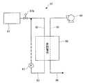
図1は、本発明の第1実施例である電気自動車10の構成の概略を表わすブロック図である。電気自動車10は、電源装置15を備えており、電源装置15から電力を供給される負荷として、高圧補機40と、駆動インバータ30を介して電源装置15に接続される駆動モータ32とを備えている。これら電源装置15と負荷との間には、配線50が設けられており、この配線50を介して、電源装置15と負荷との間で電力がやり取りされる。A. Overall configuration of the device:
FIG. 1 is a block diagram showing an outline of the configuration of an
電源装置15は、燃料電池システム22と、キャパシタ24と、2次電池26とを備えている。燃料電池システム22は、後述するように発電の本体である燃料電池を備えている。この燃料電池システム22が備える燃料電池とキャパシタ24とは、上記配線50に対して並列に接続されている。この配線50には、燃料電池へ電流が逆流するのを防止するためのダイオード42がさらに設けられている。さらに、配線50には、この配線50に対する燃料電池の接続状態を入り切りするスイッチ20が設けられている。また、配線50は、DC/DCコンバータ28に接続しており、このDC/DCコンバータ28を介して、2次電池26は配線50に接続している。また、このような電源装置15における電圧を測定するために、配線50には、電圧計52がさらに設けられている。 The
図2は、燃料電池システム22の構成の概略を表わす説明図である。燃料電池システム22は、燃料電池60と、燃料ガス供給部61と、ブロワ64と、水素循環ポンプ67と、を備えている。本実施例では、燃料電池60として、固体高分子型燃料電池を用いた。燃料ガス供給部61は、内部に水素を貯蔵し、水素ガスを燃料ガスとして燃料電池60に供給する装置である。燃料ガス供給部61は、例えば、バルブ61bを備える水素ボンベとすることができる。あるいは、水素吸蔵合金を内部に有する水素タンクを備えることとし、上記水素吸蔵合金に水素を吸蔵させることによって水素を貯蔵することとしてもよい。このような燃料ガス供給部61が貯蔵する水素ガスは、水素ガス供給路62を介して燃料電池60のアノードに供給され、電気化学反応に供される。電気化学反応で利用されなかった残りの水素ガスは、水素ガス排出路63に排出される。水素ガス排出路63は、水素ガス供給路62に接続している。水素ガス排出路63には水素循環ポンプ67が設けられている。残余の水素ガスは水素循環ポンプ67によって水素ガス供給路62に送られ、再び電気化学反応に供される。また、ブロワ64が取り込んだ圧縮空気は、酸化ガス供給路65によって、酸化ガスとして燃料電池60のカソードに供給される。燃料電池60から排出されるカソード排ガスは、カソード排ガス路66に導かれて外部に排出される。なお、燃料電池システム22において、水素ガスあるいは空気を加湿する加湿器を、水素ガス供給路62や酸化ガス供給路65にさらに設けることとしても良い。 FIG. 2 is an explanatory diagram showing an outline of the configuration of the
図1の2次電池26としては、鉛蓄電池や、ニッケル−カドミウム蓄電池、ニッケル−水素蓄電池、リチウム2次電池など種々の2次電池を用いることができる。この2次電池26は、燃料電池システム22の始動時に、燃料電池システム22の各部を駆動するための電力を供給したり、燃料電池システム22の暖機運転が完了するまでの間、各負荷に対して電力を供給する。また、燃料電池60が定常状態で発電を行なうときにも、負荷が所定の値よりも大きくなる場合には、2次電池26によって電力を補う。 As the
また、2次電池26には、2次電池26の残存容量(SOC)を検出するための残存容量モニタ27が併設されている。本実施例では、残存容量モニタ27は、2次電池26における充電・放電の電流値と時間とを積算するSOCメータとして構成されている。あるいは、残存容量モニタ27は、SOCメータの代わりに電圧センサによって構成することとしてもよい。2次電池26は、その残存容量が少なくなるにつれて電圧値が低下するという性質を有しているため、電圧を測定することによって2次電池26の残存容量を検出することができる。 The
DC/DCコンバータ28は、目標電圧値を設定することによって、燃料電池60からの出力電圧を調節し、燃料電池60の発電量を制御する。また、DC/DCコンバータ28は、2次電池26と配線50との接続状態を制御するスイッチとしての役割も果たしており、2次電池26において充放電を行なう必要のないときには、2次電池26と配線50との接続を開放する。 The DC /
電源装置15から電力の供給を受ける負荷の一つである駆動モータ32は、同期モータであって、回転磁界を形成するための三相コイルを備えている。この駆動モータ32は、駆動インバータ30を介して配線50に接続し、電源装置15から電力の供給を受ける。駆動インバータ30は、上記モータの各相に対応してスイッチング素子としてのトランジスタを備えるトランジスタインバータである。駆動モータ32の出力軸36は、減速ギヤ34を介して車両駆動軸38に接続している。減速ギヤ34は、駆動モータ32が出力する動力を、その回転数を調節した上で車両駆動軸38に伝える。 The
また、他の負荷である高圧補機40は、燃料電池60による発電を行なうために用いる補機類のことである。これらの高圧補機40は、電源装置15から供給される電力を、300V以上の電圧のまま利用する装置である。高圧補機40としては、例えば、燃料電池60に空気を供給するためのブロワ64や、水素ガス排出路63と水素ガス供給路62との間で水素ガスを循環させるための水素循環ポンプ67が挙げられる(図2参照)。さらに、燃料電池60を冷却するために、燃料電池60内部に冷却水を循環させるための冷却ポンプ(図示せず)も、高圧補機40に含まれる。これらの装置は、燃料電池システム22に含まれる装置であるが、図1においては、電源装置15の外側に、高圧補機40として示した。 The high-voltage
また、電気自動車10は、制御部48をさらに備えている。制御部48は、マイクロコンピュータを中心とした論理回路として構成され、詳しくは、予め設定された制御プログラムに従って所定の演算などを実行するCPUと、CPUで各種演算処理を実行するのに必要な制御プログラムや制御データ等が予め格納されたROMと、同じくCPUで各種演算処理をするのに必要な各種データが一時的に読み書きされるRAMと、各種の信号を入出力する入出力ポート等を備える。この制御部48は、既述した電圧計52による検出信号や、残存容量モニタ27が出力する信号、あるいは、車両の運転に関して入力される指示信号を取得する。また、DC/DCコンバータ28,スイッチ20,燃料電池システム22、駆動インバータ30、高圧補機40などに駆動信号を出力する。 The
B.燃料電池、二次電池、キャパシタの動作:
B1.燃料電池の運転:
電気自動車10の運転時には、制御部48が、車両における車速やアクセル開度に基づいて、所望の走行状態を実現するために必要な電力を算出する。電気自動車10が、燃料電池によって必要なエネルギーを得る「定常運転モード」にあるときには、制御部48は、上記必要な電力に加えて、高圧補機40が要求する電力や、2次電池26の残存容量にさらに基づいて、燃料電池60が出力すべき電力を算出する。以下で、燃料電池、二次電池、キャパシタの動作について説明する。B. Operation of fuel cell, secondary battery and capacitor:
B1. Fuel cell operation:
When the
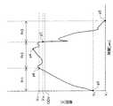
図3は、燃料電池60における出力電流と、出力電圧あるいは出力電力との関係を示すグラフである。図3に示すように、燃料電池60から出力すべき電力PFCが定まれば、燃料電池60の出力電力の特性を表す曲線より、そのときの燃料電池60の出力電流の大きさIFCが定まる。出力電流IFCが定まれば、燃料電池60の電流−電圧の特性を表す曲線(以下、この曲線を燃料電池の「特性曲線」と呼ぶことがある。)より、そのときの燃料電池60の出力電圧VFCが定まる。このようにして求めた出力電圧VFCを、制御部48が目標電圧としてDC/DCコンバータ28に対して指令することによって、燃料電池60の発電量が所望量となるように制御される。FIG. 3 is a graph showing the relationship between the output current in the
図4は、燃料電池のブロワの運転状態を定めるフローチャートである。燃料電池システム22には、図2に示すように、ブロワ64や水素循環ポンプ67などの高圧補機40が含まれる。制御部48は、上述のようにして燃料電池60の出力電流、出力電圧を定め、それらの値に基づいて、ブロワ64や水素循環ポンプ67などの、燃料電池による発電のために運転される高圧補機40の運転状態を定める。たとえば、ブロワ64に対する指示は、以下のように行われる。まず、図4のステップS10で、制御部48は、出力電流IFCを流すのに燃料電池60が必要とする空気量を計算する。そして、ステップS20で、燃料電池60が必要とする空気量を供給するのに必要な、ブロワ64の回転数を計算する。そして、ステップS30で、ブロワ64の回転数指令値をブロワ64に対して出力する。水素循環ポンプ67などの他の補機類に対する指令値も、同様に、燃料電池60の出力電流IFC、出力電圧VFCに基づいて計算され、出力される。FIG. 4 is a flowchart for determining the operating state of the blower of the fuel cell. As shown in FIG. 2, the
なお、図3に示したような、燃料電池60の出力電流に対する出力電圧の値、あるいは出力電力の値は、燃料電池60の内部温度によって変化する。したがって、上記のように燃料電池60の出力電圧(目標電圧)VFCを定めるときには、燃料電池60の内部温度をさらに考慮することが望ましい。Note that the output voltage value or the output power value with respect to the output current of the
B2.二次電池の充放電:
本実施例の電気自動車10では、負荷の大きさが所定の値以上であって、2次電池26の残存容量が充分に大きい場合には、2次電池26からも負荷に対して電力が供給される。このような場合には、制御部48は、2次電池26からも電力が供給されることを考慮して、燃料電池60が出力すべき電力を決定し、DC/DCコンバータ28における目標電圧を設定する。図3に示すように、燃料電池60の出力電圧は、負荷が大きく出力電流が大きいほど低くなる。また、2次電池26は、残存容量が大きいほど、その出力電圧が高くなるという性質を有している。そのため、負荷の大きさが所定の値以上であって、2次電池26の残存容量が充分に大きい場合には、DC/DCコンバータ28における目標電圧、すなわち、燃料電池60の出力電圧は、2次電池26の出力電圧よりも低い値となる。これによって、燃料電池60からだけでなく、2次電池26からも高圧補機40あるいは駆動モータ32に対して電力が供給されるようになる。B2. Charge / discharge of secondary battery:
In the
これに対して、2次電池26の残存容量が所定の値以下になると、2次電池26を充電する必要が生じる。このとき、負荷の大きさがある程度小さく、燃料電池60の出力に余裕がある場合には、燃料電池60によって2次電池26の充電が行なわれる。2次電池26の充電を行なう場合には、負荷に対して供給すべき電力に加えて、この2次電池26を充電するための電力が得られるように、燃料電池60が出力すべき電力、すなわち燃料電池60の運転状態が決定される(図3参照)。2次電池26は、残存容量が少ないほど、その出力電圧が低くなるという性質を有している。そのため、2次電池26の残存容量が所定の値以下の場合には、DC/DCコンバータ28において設定される目標電圧、すなわち燃料電池60の出力電圧は、2次電池26の出力電圧よりも高い値となる。これによって、燃料電池60は、高圧補機40あるいは駆動モータ32に対して電力が供給するだけでなく、2次電池26の充電を行なうようになる。 On the other hand, when the remaining capacity of the
B3.キャパシタの充放電:
また、本実施例の電気自動車10では、キャパシタ24も充放電を繰り返す。キャパシタ24は、これに残存する電荷量と出力電圧とが1対1に対応しており、残存する電荷量が多いときほど出力電圧が高く、少ないときほど出力電圧が低くなる。キャパシタ24は、図1に示すように、配線50に対して燃料電池60と並列に接続されている。そのため、燃料電池60の発電時に負荷の大きさが変動して配線50における電圧(電圧計52によって測定可能である)が変動すると、キャパシタ24の電荷量は、配線50の電圧に応じて変化する。配線50の電圧が上昇するときには、キャパシタ24は、燃料電池60から電力の供給を受け、キャパシタ電圧が配線50の電圧に等しくなるまで残存電荷量を増す。また、配線50の電圧が低下するときには、キャパシタ24は、燃料電池60と共に負荷に対して電力を供給し、キャパシタ電圧が配線50の電圧に等しくなるまで残存電荷量を減らす。すなわち、キャパシタ24は、配線50の電圧に応じて充放電を行なう。B3. Capacitor charge / discharge:
Further, in the
電気自動車10では、制動時(車両の走行時に運転者がブレーキを踏み込む動作を行なったとき)には、駆動モータ32を発電機として用いることによって、車軸の有する運動エネルギを電気エネルギに変換し、これを回収する。本実施例では、このような回生において電力として回収されるエネルギは、キャパシタ24によって吸収される。キャパシタ24は、上記2次電池26に比べてパワー密度の高い蓄電手段であり、充放電効率も高い蓄電手段である。すなわち、短時間のうちに充放電可能な電力量が多い。したがって、キャパシタ24を用いることで、車両の運転者がブレーキを踏み込むような短い制動時間に回生運転モードを実行する際に、回生によって生じた電力を効率よく回収することができる。 In the
電気自動車10において、駆動モータ32が発電し回生が行われると、駆動モータ32側から駆動インバータ30を介して配線50に対して電力が供給される。本実施例では、このような回生時に駆動モータ32から配線50に対して電力が供給されるときの電圧(以下、説明を簡単にするために「駆動モータ32からの出力電圧Vg」という)は、駆動モータの回転数や加速度の大きさによって変動するが、定常運転モード時に燃料電池60から電力が供給される際の配線50の電圧の上限よりも高くなりうるように設定されている。In the
図3に示すように、燃料電池60の出力電圧は、負荷が大きく出力電流が大きいほど低くなる。よって、燃料電池60から電力が供給される際の配線50の電圧の上限は、燃料電池60の開放電圧OCVである。燃料電池60の「開放電圧」とは、燃料電池60を回路から切り離した状態での、燃料電池60の端子間電圧である。スイッチ20がONであり、燃料電池60とキャパシタ24が並列に接続されているときには、キャパシタ24の端子間電圧は燃料電池60の出力電圧と等しくなっている。よって、燃料電池60から電力が供給される際には、キャパシタ24の端子間電圧は、最大でも開放電圧OCVである。 As shown in FIG. 3, the output voltage of the
これに対して、駆動モータ32からの出力電圧Vgは、前述のように燃料電池60の開放電圧OCVよりも高い値を取りうる。よって、制御部48が、駆動モータ32からの出力電圧Vgを、キャパシタ24の端子間電圧よりも高く設定することで、駆動モータ32が発電した回生エネルギーはキャパシタ24に蓄えられる。その結果、キャパシタ24の端子間電圧が燃料電池の開放電圧OCVを上回ることもある。回路50には、ダイオード42が設けられているので、キャパシタ24の端子間電圧が燃料電池の開放電圧OCVを上回っても、キャパシタ24から燃料電池システム22に向けて電流が流れることはない。On the other hand, the output voltage Vg from the
C.定常運転モードと間欠運転モード:
C1.定常運転モードと間欠運転モードの切り換え:
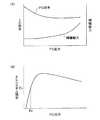
図5は、燃料電池60の出力の大きさと、エネルギ効率との関係を表わす説明図である。図5(A)は、燃料電池60の効率および燃料電池の補機類が要する動力と、燃料電池60の出力との関係を示す。図5(A)に示すように、燃料電池60の出力が大きくなるほど、燃料電池60単体での発電効率は次第に低下する。一方で、燃料電池60の出力が小さくなっても、燃料電池の補機類を駆動するために消費する動力は、それに比例して小さくなるわけではない。したがって、燃料電池60の出力が小さくなると、燃料電池60の出力に対する燃料電池の補機類が消費する動力は相対的に大きくなる。C. Steady operation mode and intermittent operation mode:
C1. Switching between steady operation mode and intermittent operation mode:
FIG. 5 is an explanatory diagram showing the relationship between the magnitude of the output of the
図5(B)は、燃料電池60の出力と、燃料電池システム22全体の効率との関係を示す。図5(A)に示した燃料電池60単体の効率と燃料電池の補機類の消費する動力に基づいて、燃料電池システム22全体の効率を求めると、図5(B)に示すようになる。すなわち、システム効率は、燃料電池60の出力が所定の値のときに最も高くなり、燃料電池60の出力が小さいときには、燃料電池システム22全体のエネルギ効率が低くなる。例えば出力がP0以下の領域では、図5に示すように、システム効率E0は、最大効率の6割程度と極端に低くなる。FIG. 5B shows the relationship between the output of the
本実施例の電気自動車10では、燃料電池システム22全体の効率が悪くなる低負荷時には、燃料電池システム22を回路50から切り離し、燃料電池60によるモータ32への電力の供給を停止する。これにより、システム全体のエネルギ効率が低下するのを防止する。燃料電池システム22が回路に接続され、燃料電池60が負荷の大きさに応じた電力をモータ32に供給するような運転状態を、「定常運転モード」と呼ぶ。これに対して、キャパシタ24によってモータ32に電力が供給され、燃料電池60は負荷の大きさに応じた電力をモータ32に供給しない運転状態を「間欠運転モード」と呼ぶ。 In the
図6は、電気自動車10の運転モードの切換え手順を表わすフローチャートである。本ルーチンは、定常運転モードにおいて開始される。定常運転モードにおいては、燃料電池60の高圧補機40は、負荷に応じて燃料電池60がモータ32に電力を供給できるように、運転される。このような運転を、高圧補機40の「定常運転」と呼ぶ。本ルーチンが実行されると、制御部48は、まず、電圧計52が検出する配線50の電圧値VCを読み込む(ステップS110)。そして、この電圧値VCと、あらかじめ定めた所定の基準電圧値V2とを比較する(ステップS120)。FIG. 6 is a flowchart showing a procedure for switching the operation mode of
基準電圧値V2とは、定常運転モードから間欠運転モードに切り替えるか否かの判断を行なうための基準として、予め制御部48内に記憶されているものである。配線50の電圧値VCが基準電圧値V2よりも小さい場合に、燃料電池システム22全体のエネルギ効率が許容できる程度となるように、基準電圧値V2は定められる。基準電圧値V2は燃料電池60の開放電圧OCVよりもある程度低い値に設定される。図3に示すように、燃料電池60の電圧は、開放電圧OCVより低い値しかとりえず、また、図3および図5(A),図5(B)に示すように、燃料電池60の電圧が高く出力電力が低い状態では、燃料電池システム22全体のエネルギ効率が低くなるためである。基準電圧値V2が、特許請求の範囲にいう「第3の基準電圧」である。基準電圧値V2は、たとえば、燃料電池の開放電圧の80〜90%の値とすることができる。The reference voltage value V2 is stored in the
ステップS120において、配線50の電圧値VCが基準電圧値V2よりも小さいと判断され、ステップS120の判定結果がNoとなるときには、ステップS110に戻る。すなわち、定常運転モードが維持される。その後、配線50の電圧値VCが基準電圧値V2以上となるまで、ステップS110およびステップS120の動作が繰り返される。この間、電気自動車10は、定常運転モードを維持する。In step S120, when it is determined that the voltage value VC of the
ステップS120において、配線50の電圧値VCが基準電圧値V2以上であると判断され、ステップS120の判定結果がYesとされると、制御部48は、スイッチ20に駆動信号を出力してこれを開状態とする(ステップS130)。このようにスイッチ20を開状態とすると、燃料電池60の回路50に対する接続が開放されるため(図1参照)、燃料電池60からモータ32への電力の供給は停止される。モータ32へは、キャパシタ24から電力が供給されるようになり、電気自動車10は、間欠運転モードに移行する。燃料電池60の高圧補機40は、ステップS130以降では、一定の低出力で運転される。この間欠運転モードにおける一定の低出力での高圧補機40の運転を「待機運転」と呼ぶ。「待機運転」とは、各補機の単位時間当たりの消費電力が「定常運転」における最低の単位時間当たりの消費電力よりも小さくなるような、補機の運転状態である。一方、キャパシタ24は、既述したようにパワー密度が高く、充放電効率も高い。このため、キャパシタ24は、スイッチ20が開状態とされたときに、速やかに負荷が要求する電力を出力することができる。In step S120, when it is determined that the voltage value VC of the
間欠運転モードに移行すると、制御部48は、再び電圧計52が検出する配線50の電圧値VCの読み込みを行なう(ステップS140)。次に、読み込んだ電圧値VCと、基準電圧値V1とを比較する(ステップS150)。ここで、基準電圧値V1とは、間欠運転モードから通常運転モードに切り替えるか否かの判断を行なうための基準として、予め制御部48内に記憶されているものである。基準電圧値V1は、既述した基準電圧値V2の近傍の値であるが基準電圧値V2よりも低い値として設定されている。基準電圧値V1は、基準電圧値V2の近傍の値であるため、配線50の電圧値VCが基準電圧値V1以下である場合には、燃料電池システム22全体のエネルギ効率は許容できる程度となる。なお、基準電圧値V2は、基準電圧値V2の80%以上100%未満の値とすることができる。この基準電圧値V1は、基準電圧値V2の90%以上であることが好ましく、さらに、基準電圧値V2の95%以上であることが好ましい。基準電圧値V1が、特許請求の範囲にいう「第4の基準電圧」である。When shifting to the intermittent operation mode, the
ステップS150において、配線50の電圧値VCが基準電圧値V1よりも大きいと判断され、ステップS150の判定結果がNoとなるときには、処理は、燃料電池の補機停止ルーチンであるステップS160を経て、ステップS140に戻る。そして、配線50の電圧値VCが基準電圧値V1以下になるまで、ステップS140〜S160の動作が繰り返される。すなわち、配線50の電圧値VCが基準電圧値V1よりも大きいときには、「間欠運転モード」が維持される。その間、制御部48は、燃料電池60の高圧補機40について待機運転を行うか、または後述するように高圧補機40の運転を停止する。In step S150, when it is determined that the voltage value VC of the
配線50の電圧値VCが基準電圧値V1よりも大きいときに燃料電池システム22で電力の供給を行うこととすると、前述のように、出力電力に対する高圧補機40の消費電力の割合が大きくなるので、電気自動車10全体として効率が低くなる。このため、本実施例においては、VCが基準電圧値V1よりも大きいときには、燃料電池60を回路50から切り離し、キャパシタ24からモータ32に電力を供給する。そして、燃料電池60の高圧補機40については、待機運転するかまたは運転を停止することとして、電気自動車10全体の効率を高く維持するものである。Assuming that the
ステップS150において、配線50の電圧値VCが基準電圧値V1以下であると判断され、ステップS150の判定結果がYesとなると、制御部48は、スイッチ20に駆動信号を出力してこれを閉状態とし(ステップS170)、燃料電池システム22を、負荷に応じてモータ32に電力を供給するように運転する。すなわち、燃料電池60の高圧補機40の運転を定常運転に切り換える。ステップS170の処理によって、燃料電池60によるモータ32への電力の供給が再開される。そして、電気自動車10は定常運転モードに移行する。その後、制御部48は、処理を終了する。In step S150, when it is determined that the voltage value VC of the
図7は、定常運転モードと間欠運転モードとが交互に切り替わるときの、燃料電池60の出力電圧およびキャパシタ24の電圧を示す説明図である。ステップS130においてスイッチ20を開状態とし、定常運転モードから間欠運転モードに切り替わったときを、図7に「OFF」と記載して示す。そして、ステップS170においてスイッチ20を閉状態とし、間欠運転モードから定常運転モードに切り替わったときを、図7に「ON」と記載して示す。 FIG. 7 is an explanatory diagram showing the output voltage of the
たとえば、グラフ中の状態p1において、電気自動車10は間欠運転モードから定常運転モードに移行している。定常運転モードにおいては、燃料電池システム22とキャパシタ24は並列に接続されるので、図7においても、キャパシタ電圧と燃料電池の電圧とは一致している。その後、状態p2を経て、状態p3において電気自動車10は定常運転モードから間欠運転モードに移行している。 For example, in the state p1 in the graph, the
間欠運転モードにおいては、燃料電池システム22が回路50から切り離される。そして、制御部48は、燃料電池システム22を待機運転する。このため、間欠運転モードにおいては、キャパシタ電圧が電気自動車の運転状態に応じて変化するのに対して、燃料電池60の電圧は、待機運転による一定電圧となる。待機運転は低出力の運転であるため、間欠運転モードにおいては、燃料電池60の端子間電圧はOCV近辺の値となる。図7において、燃料電池60の端子間電圧を一点鎖線で示す。状態p3以降、間欠運転モードで運転された電気自動車10は、その後、状態p4を経て、状態p5で再び定常運転モードに移行している。 In the intermittent operation mode, the
間欠運転モードにおいては、キャパシタ24がモータ32に電力を供給するので、時間の経過とともにキャパシタ電圧は低下するはずである。しかし、図7中、間欠運転モードにおいてもキャパシタ電圧が上昇している場合がある。これは、そのときに回生が行われているためである。回生が行われる結果、状態p4近傍において、キャパシタ電圧は、燃料電池の開放電圧OCVを超える値となっている。 In the intermittent operation mode, since the
一方、定常運転モードにおいては、燃料電池60が電力を供給しているため、燃料電池60の出力電圧の指令値が燃料電池60およびキャパシタ24の電圧となる。よって、図3に示した燃料電池の特性より、燃料電池60が比較的多くの電力を供給する場合は、燃料電池60およびキャパシタ24の電圧は低くなり、燃料電池60が比較的少ない電力を供給する場合は、燃料電池60およびキャパシタ24の電圧は高くなる。ただし、定常運転モードにおいても回生が行われるため、電圧計52によって測定されるキャパシタ24の電圧は、回生によって上昇することがある。 On the other hand, in the steady operation mode, since the
なお、間欠運転モード時には、上記のようにキャパシタ24から負荷に対して電力を供給するだけでなく、さらに2次電池からも負荷に対して電力を供給することとしても良い。間欠運転モードとすべき低負荷状態が長く続くときや、2次電池26の残存容量が充分に多いときには、キャパシタ24に加えて、さらに2次電池26を用いることとしてもよい。 In the intermittent operation mode, not only power is supplied from the
C2.補機の停止:
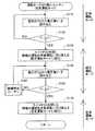
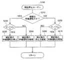
図8は、補機停止ルーチンS160の内容を示すフローチャートである。補機停止ルーチンS160では、状況に応じて、燃料電池60による発電を行なうために用いる高圧補機40の運転を停止する処理が行われる。補機停止ルーチンにおいては、制御部48は、まず、ステップS210で、高圧補機40が待機運転されているか否かを判定する。高圧補機40が待機運転中であり、ステップS210の判定結果がYesとなった場合は、次に、ステップS220で、配線50の電圧値VCが基準電圧値V01よりも大きいか否かが判定される。C2. Stop auxiliary equipment:
FIG. 8 is a flowchart showing the contents of the auxiliary machine stop routine S160. In the auxiliary machine stop routine S160, processing for stopping the operation of the high-pressure
基準電圧値V01は、燃料電池60の開放電圧OCVの近傍の値である。基準電圧値V01は、燃料電池60の高圧補機40を停止するか否かの判断を行なうための基準として、予め制御部48内に記憶されている。基準電圧値V01は、以下のような条件を満たすように設定される。すなわち、配線50の電圧値VCが基準電圧値V01よりも大きく燃料電池60の高圧補機40が停止されている状態から、電圧値VCが基準電圧値V01を下回り、電気自動車10が定常運転モードに移行しても、燃料電池60の高圧補機40が定常状態に移行し指定された電力を供給できる状態になるまでの間、電気自動車10の運転に支障が出ないようにキャパシタ24が電力を供給できるだけの値に、基準電圧値V01は設定される。基準電圧値V01が、特許請求の範囲にいう「第1の基準電圧」である。The reference voltage value V01 is a value near the open circuit voltage OCV of the
基準電圧値V01は、たとえば燃料電池60の開放電圧OCV近傍の値とすることができる。「燃料電池60の開放電圧OCV近傍の値」とは、燃料電池60の開放電圧OCV近傍の値の80%以上120%未満の値を意味する。この基準電圧値V01は、基準電圧値V2の90%以上110%未満であることが好ましく、さらに、基準電圧値V2の95%以上105%未満であることが好ましい。The reference voltage value V01 can be set to a value near the open circuit voltage OCV of the
ステップS220において、電圧値VCが基準電圧値V01よりも大きく、ステップS220の判定結果がYesである場合には、ステップS230で高圧補機40の運転が停止される。電圧値VCが基準電圧値V01以下であり、ステップS220の判定結果がNoである場合には、ステップS240で高圧補機40の待機運転が継続される。In step S220, when the voltage value VC is larger than the reference voltage value V01 and the determination result in step S220 is Yes, the operation of the high-voltage
一方、ステップS210において高圧補機40が待機運転されておらず、ステップS210の判定結果がNoとなった場合は、次に、ステップS250で、配線50の電圧値VCが基準電圧値V02未満であるか否かが判定される。On the other hand, if the high-voltage
基準電圧値V02は、燃料電池60の開放電圧OCVの近傍の値である。基準電圧値V02は、燃料電池60の高圧補機40の運転を再開するか否かの判断を行なうための基準として、予め制御部48内に記憶されている。基準電圧値V02は、以下の条件を満たすように設定される。すなわち、配線50の電圧値VCが基準電圧値V02よりも大きく燃料電池60の高圧補機40が停止されている状態から、電圧値VCが基準電圧値V02を下回り、電気自動車10が定常運転モードに移行しても、燃料電池60の高圧補機40が定常状態に移行し指定された電力を供給できる状態になるまでの間、電気自動車10の運転に支障が出ないようにキャパシタ24が電力を供給できるだけの値に、基準電圧値V02は設定される。基準電圧値V02は、燃料電池60の開放電圧OCV近傍の値であって、基準電圧値V01以下の値とすることが好ましい。基準電圧値V02が、特許請求の範囲にいう「第2の基準電圧」である。The reference voltage value V02 is a value near the open circuit voltage OCV of the
電圧値VCが基準電圧値V02以上であり、ステップS250の判定結果がNoである場合には、ステップS260で高圧補機40の停止が維持される。電圧値VCが基準電圧値V02より低く、ステップS250の判定結果がYesである場合には、ステップS270で高圧補機40の待機運転が再開される。If the voltage value VC is equal to or higher than the reference voltage value V02 and the determination result in step S250 is No, the high-voltage
キャパシタ24の端子間電圧がOCVより高いときには、キャパシタ24の端子間電圧は燃料電池60の電圧よりも高くなる(図3参照)。よって、キャパシタ24の端子間電圧がOCVより高いときには、スイッチ20の状態によらず、燃料電池60からモータ32には電力は供給されない。よって、燃料電池60の高圧補機40を停止するか否か、高圧補機40の待機運転を再開するか否かの判断を行なうための基準である基準電圧値V01、V02を、燃料電池60の開放電圧OCV近傍の値とすれば、燃料電池60がモータ32に電力を供給しない状態のときに、高圧補機40を停止するという制御を行うことができる。When the terminal voltage of the
図9は、図7における状態p3から状態p5までの間欠運転モードの区間を拡大して示した図である。図9の状態p3においては、電気自動車10は間欠運転モードに移行した直後である。基準電圧値V2は、OCVよりも低い値に設定されているので、このとき、燃料電池60の高圧補機40は、定常運転から待機運転に移行して、待機運転を行っている(図6のステップS130参照)。したがって、ステップS210の判定結果は、Yesとなる。また、図9の状態p3においては、電圧はV01よりも低いため、ステップS220における判定結果はNoとなり、ステップS240において高圧補機40の待機運転は継続される。FIG. 9 is an enlarged view of the intermittent operation mode section from state p3 to state p5 in FIG. In the state p3 of FIG. 9, the
図9においては、状態p3から時間の経過とともに電圧VCが上昇しているが、状態p6に至るまでは、電圧VCはV01を超えていない。したがって、運転状態が状態p3から状態p6にある間の区間Pr1においては、補機停止ルーチンS160内においては、ステップS210,S220,S240の処理が行われ、高圧補機40は待機運転される。電気自動車10の運転状態が図9の状態p6を超えると、電圧VCがV01を超えるので、ステップS220の判定結果はYesとなる。その結果、ステップS230において高圧補機40の運転が停止される。In FIG. 9, the voltage VC increases as time elapses from the state p3, but the voltage VC does not exceed V01 until the state p6 is reached. Therefore, in the section Pr1 during which the operating state is from the state p3 to the state p6, the processes of steps S210, S220, and S240 are performed in the auxiliary machine stop routine S160, and the high-pressure
図9においては、状態p3から時間の経過とともにキャパシタ電圧VCが上昇しているが、電圧VCが減少していった場合には、キャパシタ電圧VCが基準電圧値V1を下回った時点でステップS150(図6参照)の判定結果がYesとなる。そして、ステップS170で、高圧補機40は定常運転を開始される。すなわち、ステップS130で開始された高圧補機40の待機運転は、キャパシタ電圧VCが基準電圧値V1を下回り、ステップS170で定常運転が開始されることで終了するか(図6参照)、または、キャパシタ電圧VCが基準電圧値V01を上回り、ステップS230(図8参照)で運転を停止されることで終了する。In FIG. 9, the capacitor voltage VC increases as time elapses from the state p3, but when the voltage VC decreases, the time when the capacitor voltage VC falls below the reference voltage value V1. Thus, the determination result in step S150 (see FIG. 6) is Yes. In step S170, the high-pressure
ステップS230で高圧補機40の運転が停止されると、その後は、ステップS210の判定結果はNoとなり、ステップS250で、配線50の電圧値VCが基準電圧値V02未満であるか否かが判定される。状態p6以降、電圧VCの値は上昇したり下降したりしているが、状態p7に至るまでは、V02よりも高い値を保っている。したがって、運転状態が状態p6から状態p7にある間の区間Pr2においては、高圧補機40の運転は停止される。電気自動車10の運転状態が図9の状態p7を超えると、電圧VCがV02を下回るので、ステップS250の判定結果はYesとなる。その結果、ステップS270において高圧補機40の待機運転が再開される。その後、運転状態が状態p5に至ると、電気自動車10は、定常運転モードに移行する(図7参照)。その結果、燃料電池60の高圧補機40も、定常運転される。すなわち、運転状態が状態p7から状態p5にある間の区間Pr3においては、区間Pr1と同様、間欠運転モード中にあって燃料電池60の高圧補機40は待機運転される。When the operation of the high-voltage
図9においては、状態p7から時間の経過とともにキャパシタ電圧VCが下降しているが、電圧VCが上昇していった場合には、キャパシタ電圧VCが基準電圧値V01を上回った時点でステップS220(図8参照)の判定結果がYesとなる。そして、ステップS230で、高圧補機40の運転が停止される。すなわち、ステップS270で開始された高圧補機40の待機運転は、キャパシタ電圧VCが基準電圧値V1を下回り、ステップS170で定常運転が開始されることで終了するか(図6参照)、または、キャパシタ電圧VCが基準電圧値V01を上回り、ステップS230(図8参照)で運転を停止されることで終了する。In FIG. 9, the capacitor voltage VC decreases with the passage of time from the state p7, but when the voltage VC increases, the time when the capacitor voltage VC exceeds the reference voltage value V01. In step S220 (see FIG. 8), the determination result is Yes. In step S230, the operation of the high pressure
第1実施例においては、キャパシタ電圧VCが基準電圧値V2を超えてから基準電圧値V1を下回るまでの間、間欠運転モードによる運転が行われ、燃料電池60によるモータ32への負荷に応じた電力の供給は行われない。そして、間欠運転モード中は、燃料電池60の高圧補機40が待機運転され(図9の区間Pr1,Pr3)、または高圧補機40の運転が停止される(図9の区間Pr2)。したがって、モータ32が低出力で運転されるときにも燃料電池60によって負荷に応じた発電が行われる場合に比べて、電気自動車10全体の効率を高くすることができる。In the first embodiment, the operation in the intermittent operation mode is performed from when the capacitor voltage VC exceeds the reference voltage value V2 until it falls below the reference voltage value V1 , and the load on the
また、キャパシタ電圧VCが基準電圧値V02を下回ると定常運転モードへの以降に先立って高圧補機40が待機運転されるので(図9の区間Pr3)、定常運転モードに移行した直後も、燃料電池システム22の発電量の時間遅れが少ない。さらに、キャパシタ電圧VCが基準電圧値V01を上回るまでは、間欠運転モードにおいても高圧補機40が待機運転される(図9の区間Pr1)。このため、電気自動車10が間欠運転モードに移行した後、すぐにキャパシタ電圧が下がって再度、定常運転モードに移行しても、燃料電池システム22の発電量の時間遅れが少ない。Further, if the capacitor voltage VC falls below the reference voltage value V02 , the high-voltage
また、第1実施例においては、高圧補機40の運転再開の判定基準となる基準電圧値V02が、高圧補機40の運転停止の判定基準となる基準電圧値V01よりも低い値に設定されている。このため、キャパシタ電圧VCが微小変動を繰り返しても、その変動範囲がV01とV02の間にある限り、高圧補機40の運転停止と再開が頻繁に繰り返されることがない。In the first embodiment, the reference voltage value V02 that is a criterion for resuming operation of the high-voltage
また、第1実施例においては、間欠運転モードへの移行の判定基準となる基準電圧値V1が、定常運転モードへの移行の判定基準となる基準電圧値V2よりも低い値に設定されている。このため、キャパシタ電圧VCが微小変動を繰り返しても、その変動範囲がV1とV2の間にある限り、定常運転モードと間欠運転モードとが頻繁に繰り返されることがない。In the first embodiment, the reference voltage value V1 that is a determination criterion for the transition to the intermittent operation mode is set to a value that is lower than the reference voltage value V2 that is the determination criterion for the transition to the steady operation mode. ing. For this reason, even if the capacitor voltage VC repeatedly fluctuates, the steady operation mode and the intermittent operation mode are not frequently repeated as long as the fluctuation range is between V1 and V2 .
また、第1実施例においては、V01>V2、V02>V1の関係が成立している。このため、高圧補機40を停止している状態の前後に、待機運転を行うことができる。In the first embodiment, the relations V01 > V2 and V02 > V1 are established. For this reason, the standby operation can be performed before and after the state where the high-pressure
さらに、第1実施例においては、基準電圧値V01とV02が、燃料電池の開放電圧OCV近傍の値に設定されている。このため、高圧補機40の運転を再開してから、電気自動車10が燃料電池60から電力を得る定常運転モードに移行するまでの間、キャパシタ24に蓄えられたエネルギーで、十分、電気自動車10を運転することができる。Further, in the first embodiment, the reference voltage values V01 and V02 are set to values near the open circuit voltage OCV of the fuel cell. Therefore, the energy stored in the
D.変形例:
この発明は上記の実施例や実施形態に限られるものではなく、その要旨を逸脱しない範囲において種々の態様において実施することが可能であり、例えば次のような変形も可能である。D. Variation:
The present invention is not limited to the above-described examples and embodiments, and can be carried out in various modes without departing from the gist thereof. For example, the following modifications are possible.
D1.変形例1:
図10は、間欠運転モード中のキャパシタ電圧VCの変化を示した図である。
図10に示す態様は、図8に示す処理において、基準電圧値V01と基準電圧値V02をともに同じ値V012とした場合の態様である。図10に示す態様においては、配線50の電圧値VCが基準電圧値V012よりも大きいときに、燃料電池60の高圧補機40の運転を停止し、電圧値VCが基準電圧値V012よりも低くなったときに、燃料電池60の高圧補機40の待機運転を再開する。その結果、間欠運転モード中において、区間Pr4と区間Pr6においては高圧補機40は待機運転され、区間Pr5においては、高圧補機40は停止される。このような態様としても、電気自動車10全体の効率を高くすることができる。D1. Modification 1:
FIG. 10 is a diagram showing changes in the capacitor voltage VC during the intermittent operation mode.
The mode shown in FIG. 10 is a mode when the reference voltage value V01 and the reference voltage value V02 are both set to the same value V012 in the process shown in FIG. In the embodiment shown in FIG. 10, when the voltage value VC of the
上記実施例では、配線50の電圧値VCが基準電圧値V01よりも大きいときに、燃料電池60の高圧補機40の運転を停止し、電圧値VCが基準電圧値V02よりも低くなったときに、燃料電池60の高圧補機40の待機運転を再開していた。しかし、これら二つの基準電圧値は、図10に示す態様のように、同じ値V012であってもよい。また、基準電圧値V01、V02は、いずれも燃料電池60の開放電圧OCVよりも高い値であったが、高圧補機40の待機運転を行うか、高圧補機40を停止するかの判断の基準となる電圧は、図10に示す態様のように、燃料電池60の開放電圧OCVよりも低い値であってもよい。In the above embodiment, when the voltage value VC of the
D2.変形例2:
図11は、間欠運転モード中のキャパシタ電圧VCの変化を示した図である。図11に示す態様においては、高圧補機40の運転を停止すべきか否かを判断するための電圧値V01(図8のステップS220参照)が、定常運転モードから間欠運転モードに移行すべきか否かの判断の基準値である基準電圧値V2(図6のステップS120参照)と等しい。そして、高圧補機40の運転を再開すべきか否かを判断するための電圧値V02(図8のステップS250参照)が、間欠運転モードから定常運転モードに移行すべきか否かの判断の基準値である基準電圧値V1(図6のステップS150参照)と等しい。その結果、高圧補機40の運転を停止する前の待機運転、および運転再開時の待機運転は行われない。D2. Modification 2:
FIG. 11 is a diagram illustrating a change in the capacitor voltage VC during the intermittent operation mode. In the mode shown in FIG. 11, whether or not the voltage value V01 (see step S220 in FIG. 8) for determining whether or not to stop the operation of the high-pressure
上記のような態様とする結果、区間Pr7で示す間欠運転モード中において、高圧補機40は停止される。このような態様としても、電気自動車10全体の効率を高くすることができる。なお、間欠運転モードから定常運転モード平行した直後は、水素ガスや圧縮空気が制御部48が計算した量だけ燃料電池60に送られない可能性もある(図2参照)。しかし、キャパシタ24の容量を十分に大きく取っておけば、その間の電力は、キャパシタ24から供給されうる。 As a result of the above aspects, the high-pressure
D3.変形例3:
上記の実施例では、所定の条件下で高圧補機40を停止し、または待機運転することで、電気自動車10全体としての効率を高めていた。そして、高圧補機40の例として、酸素含有ガスである圧縮空気を燃料電池60に送るブロワ64(図2参照)、燃料ガスである水素を燃料電池60に送る水素循環ポンプ67(図2参照)、燃料電池60内部に冷却水を循環させるための冷却ポンプ(図示せず)などを示した。しかし、所定の条件下で運転を停止し、または待機運転を行う補助装置はこれらに限られるものではない。たとえば、燃料電池を運転する際に使用される各バルブやセンサなど、高圧機器以外の機器について、運転を停止等することとしてもよい。すなわち、燃料電池による発電のために運転される補助装置を、所定の条件下で停止したり、待機運転することで、電気自動車10全体としての効率を高めることができる。D3. Modification 3:
In the above-described embodiment, the efficiency of the
D4.変形例4:
図6に示した間欠運転判断処理ルーチンにおいては、運転状態を、定常運転モードから間欠運転モードに変更するかどうかの判断は、配線50の電圧に基づいて行なったが、異なる値に基づくこととても良い。既述したように、配線50の電圧に基づくこととすれば、所望のタイミングで正確に切り替えを行なうことができるが、燃料電池60の出力は、負荷要求に応じて増減するため、負荷の大きさに基づいて判断しても良い。あるいは、燃料電池60の出力電流値に基づいて、定常運転モードから間欠運転モードへの切り替えの判断をしても良い。燃料電池システム22のエネルギ効率が望ましくない程度に低下する状態となるときに、間欠運転モードが実行されればよい。D4. Modification 4:
In the intermittent operation determination processing routine shown in FIG. 6, whether or not the operation state is changed from the steady operation mode to the intermittent operation mode is determined based on the voltage of the
D5.変形例5:
また、第1実施例では、配線50に対する燃料電池60の接続を入り切りするスイッチ20は、燃料電池60の2つの端子のそれぞれに対して設けたが、どちらか一方だけにスイッチを設けることとしても良い。間欠運転モードにおいて、燃料電池60からの出力を、停止させることができればよい。D5. Modification 5:
In the first embodiment, the
D6.変形例6:
既述した実施例では、燃料電池システム22は、燃料ガスとして水素ガスを用いることとした。これに対して、燃料ガスとして、改質ガスを用いる構成も可能である。このような場合には、図2に示した燃料電池システム22において、燃料ガス供給部61として、水素を貯蔵する装置に代えて、改質ガスを生成する装置を備えることとすればよい。具体的には、改質反応に供する改質燃料および水を貯蔵するタンクや、改質触媒を備える改質器、さらに、改質ガス中の一酸化炭素濃度を低減するための反応を促進する触媒を備える反応部などを備えることとすればよい。D6. Modification 6:
In the embodiment described above, the
D7.変形例7:
本発明は、以下のような様々な態様で実現することができる。D7. Modification 7:
The present invention can be realized in various modes as follows.
(1)態様1
所定の負荷に電力を供給する配線に対して並列に接続された燃料電池およびキャパシタを備える電源装置の運転方法であって、
(a)前記キャパシタの電圧を検出する工程と、
(b)前記燃料電池による発電のために運転される補助装置が運転されている状態において、前記キャパシタの電圧が第1の基準電圧に達したときに、前記補助装置の運転を停止する工程と、を備える電源装置の運転方法。(1) Aspect 1
A method of operating a power supply device including a fuel cell and a capacitor connected in parallel to a wiring for supplying power to a predetermined load,
(A) detecting the voltage of the capacitor;
(B) stopping the operation of the auxiliary device when the voltage of the capacitor reaches a first reference voltage in a state where the auxiliary device operated for power generation by the fuel cell is operated; A method for operating a power supply apparatus comprising:
(2)態様2
態様1の電源装置の運転方法であって、さらに、
(c)前記補助装置の運転が停止されている状態において、前記キャパシタの電圧が前記第1の基準電圧よりも小さな値を有する第2の基準電圧まで下降したときに、前記補助装置の運転を開始する工程を備える、電源装置の運転方法。(2) Aspect 2
A method for operating the power supply device according to aspect 1, further comprising:
(C) In a state where the operation of the auxiliary device is stopped, the operation of the auxiliary device is performed when the voltage of the capacitor drops to a second reference voltage having a value smaller than the first reference voltage. A method for operating a power supply device, comprising a step of starting.
(3)態様3
態様2の電源装置の運転方法であって、
前記第1および第2の基準電圧は、前記燃料電池の開放電圧近傍の所定の電圧である、運転方法。(3)
A method for operating the power supply device according to aspect 2,
The operation method, wherein the first and second reference voltages are predetermined voltages in the vicinity of an open circuit voltage of the fuel cell.
(4)態様4
態様2の電源装置の運転方法であって、さらに、
(d)前記燃料電池が前記配線に接続されている状態において、前記キャパシタの電圧が、前記第1の基準電圧以下の値を有する第3の基準電圧に達したときに、前記燃料電池の前記配線に対する接続を開放する工程と、
(e)前記燃料電池の前記配線に対する接続が開放されている状態において、前記キャパシタの電圧が、前記第2の基準電圧以下の値を有する第4の基準電圧まで下降したときに、前記燃料電池を前記配線に対して再接続する工程と、を備える電源装置の運転方法。(4) Aspect 4
A method for operating the power supply device according to aspect 2, further comprising:
(D) In a state where the fuel cell is connected to the wiring, when the voltage of the capacitor reaches a third reference voltage having a value equal to or lower than the first reference voltage, the fuel cell Opening the connection to the wiring;
(E) The fuel cell when the voltage of the capacitor drops to a fourth reference voltage having a value equal to or lower than the second reference voltage in a state where the connection of the fuel cell to the wiring is opened. And reconnecting the wiring to the wiring.
(5)態様5
態様4の電源装置の運転方法であって、
前記第3の基準電圧は、前記第1の基準電圧よりも低く前記第4の基準電圧以上の値を有し、
前記運転方法は、さらに、
(f)前記キャパシタの電圧が、前記第3の基準電圧を上回った後、前記第1の基準電圧を上回るか、または第4の基準電圧を下回るまでは、前記補助装置の運転状態を、前記キャパシタの電圧が前記第3の基準電圧より低いときの前記補助装置の運転状態よりも消費電力の低い運転状態とする工程を備える、電源装置の運転方法。(5) Aspect 5
A method for operating the power supply device according to aspect 4,
The third reference voltage has a value lower than the first reference voltage and greater than or equal to the fourth reference voltage,
The driving method further includes:
(F) After the voltage of the capacitor exceeds the third reference voltage, until the voltage exceeds the first reference voltage or falls below the fourth reference voltage, the operating state of the auxiliary device is An operation method of a power supply device comprising a step of setting an operation state in which power consumption is lower than an operation state of the auxiliary device when a voltage of a capacitor is lower than the third reference voltage.
(6)態様6
態様4の電源装置の運転方法であって、
前記第4の基準電圧は、前記第2の基準電圧よりも低い値を有し、
前記運転方法は、さらに、
(f)前記キャパシタの電圧が前記第2の基準電圧を下回った後、前記第4の基準電圧を下回るかまたは前記第1の基準電圧を上回るまでは、前記補助装置の運転状態を、前記第4の基準電圧を下回った後の前記補助装置の運転状態よりも消費電力の低い運転状態とする工程と、を備える電源装置の運転方法。(6) Aspect 6
A method for operating the power supply device according to aspect 4,
The fourth reference voltage has a lower value than the second reference voltage;
The driving method further includes:
(F) After the voltage of the capacitor falls below the second reference voltage, until the voltage drops below the fourth reference voltage or exceeds the first reference voltage, the operating state of the auxiliary device is And a step of setting the power consumption to an operation state lower than the operation state of the auxiliary device after the voltage falls below the reference voltage of 4.
(7)態様7
態様1の電源装置の運転方法であって、
前記補助装置は、前記燃料電池に燃料ガスを供給するための装置を含む、運転方法。(7) Aspect 7
A method for operating the power supply device according to aspect 1,
The operation method, wherein the auxiliary device includes a device for supplying fuel gas to the fuel cell.
(8)態様8
所定の負荷に電力を供給する電源装置であって、
前記負荷に電力を供給する配線に対して並列に接続される燃料電池システムおよびキャパシタと、
前記キャパシタの電圧を検出する電圧計と、
前記燃料電池システムの運転を制御する制御部と、を備える電源装置であって、
前記燃料電池システムは、燃料電池と、前記燃料電池による発電のために運転される補助装置と、を備え、
前記制御部は、前記補助装置が運転されている状態において、前記キャパシタの電圧が第1の基準電圧に達したときに、前記補助装置の運転を停止する指示を出力する、電源装置。(8) Aspect 8
A power supply device that supplies power to a predetermined load,
A fuel cell system and a capacitor connected in parallel to the wiring for supplying power to the load;
A voltmeter for detecting the voltage of the capacitor;
A control unit for controlling the operation of the fuel cell system, comprising:
The fuel cell system includes a fuel cell, and an auxiliary device operated for power generation by the fuel cell,
The said control part is a power supply device which outputs the instruction | indication which stops the driving | operation of the said auxiliary | assistant apparatus, when the voltage of the said capacitor reaches the 1st reference voltage in the state in which the said auxiliary | assistant apparatus is drive | operating.
(9)態様9
態様8の電源装置であって、
前記制御部は、前記補助装置の運転が停止されている状態において、前記キャパシタの電圧が前記第1の基準電圧よりも小さな値を有する第2の基準電圧まで下降したときに、前記補助装置の運転を開始する電源装置。(9) Aspect 9
A power supply device according to aspect 8,
In a state where the operation of the auxiliary device is stopped, the controller is configured such that when the voltage of the capacitor drops to a second reference voltage having a value smaller than the first reference voltage, A power supply unit that starts operation.
(10)態様10
態様9の電源装置であって、
前記第1および第2の基準電圧は、前記燃料電池の開放電圧近傍の所定の電圧である、電源装置。(10)
A power supply device according to aspect 9,
The power supply apparatus, wherein the first and second reference voltages are predetermined voltages in the vicinity of an open circuit voltage of the fuel cell.
(11)態様11
態様9の電源装置であって、さらに、
前記燃料電池と前記配線との間の接続を入り切りするスイッチを備え、
前記制御部は、
前記燃料電池が前記配線に接続されている状態において、前記キャパシタの電圧が、前記第1の基準電圧以下の値を有する第3の基準電圧に達したときに、前記スイッチを開状態とする指示を出力し、
前記燃料電池の前記配線に対する接続が開放されている状態において、前記キャパシタの電圧が、前記第2の基準電圧以下の値を有する第4の基準電圧まで下降したときに、前記スイッチを閉状態とする指示を出力する、電源装置。(11) Aspect 11
The power supply device according to aspect 9, further comprising:
A switch for turning on and off the connection between the fuel cell and the wiring;
The controller is
An instruction to open the switch when the voltage of the capacitor reaches a third reference voltage having a value equal to or lower than the first reference voltage in a state where the fuel cell is connected to the wiring. Output
When the connection of the fuel cell to the wiring is opened, the switch is closed when the voltage of the capacitor drops to a fourth reference voltage having a value less than or equal to the second reference voltage. A power supply that outputs instructions to
(12)態様12
態様11の電源装置であって、
前記第3の基準電圧は、前記第1の基準電圧よりも低く前記第4の基準電圧以上の値を有し、
前記制御部は、前記キャパシタの電圧が、前記第3の基準電圧を上回った後、前記第1の基準電圧を上回るか、または第4の基準電圧を下回るまでは、前記補助装置の運転状態を、前記キャパシタの電圧が前記第3の基準電圧より低いときの前記補助装置の運転状態よりも消費電力の低い運転状態とする、電源装置。(12) Aspect 12
A power supply device according to aspect 11,
The third reference voltage has a value lower than the first reference voltage and greater than or equal to the fourth reference voltage,
After the voltage of the capacitor exceeds the third reference voltage, the control unit keeps the operating state of the auxiliary device until the voltage exceeds the first reference voltage or falls below the fourth reference voltage. The power supply device is set to an operation state in which power consumption is lower than the operation state of the auxiliary device when the voltage of the capacitor is lower than the third reference voltage.
(13)態様13
態様11の電源装置であって、
前記第4の基準電圧は、前記第2の基準電圧よりも低い値を有し、
前記制御部は、前記キャパシタの電圧が前記第2の基準電圧を下回った後、前記第4の基準電圧を下回るかまたは前記第1の基準電圧を上回るまでは、前記補助装置の運転状態を、前記第4の基準電圧を下回った後の前記補助装置の運転状態よりも消費電力の低い運転状態とする、電源装置。(13) Aspect 13
A power supply device according to aspect 11,
The fourth reference voltage has a lower value than the second reference voltage;
The controller, after the voltage of the capacitor falls below the second reference voltage, until the lower than the fourth reference voltage or above the first reference voltage, the operating state of the auxiliary device, The power supply apparatus which is set as the driving | running state in which power consumption is lower than the driving | running state of the said auxiliary | assistant apparatus after falling below the said 4th reference voltage.
(14)態様14
態様8の電源装置であって、
前記補助装置は、前記燃料電池に燃料ガスを供給するための装置を含む、運転方法。(14) Aspect 14
A power supply device according to aspect 8,
The operation method, wherein the auxiliary device includes a device for supplying fuel gas to the fuel cell.
10…電気自動車
15…電源装置
20…スイッチ
22…燃料電池システム
24…キャパシタ
27…残存容量モニタ
28…DC/DCコンバータ
30…駆動インバータ
32…駆動モータ
34…減速ギヤ
36…出力軸
38…車両駆動軸
40…高圧補機
42…ダイオード
48…制御部
50…回路(配線)
52…電圧計
60…燃料電池
61…燃料ガス供給部
61b…バルブ
62…水素ガス供給路
63…水素ガス排出路
64…ブロワ
65…酸化ガス供給路
66…カソード排ガス路
67…水素循環ポンプ
E0…出力がP0のときの燃料電池のシステム効率
V0…出力がP0のときの燃料電池の電流
IFC…出力電流
OCV…開放電圧
P0…燃料電池の出力
PFC…電力
Pr1〜Pr7…区間
S160…補機停止ルーチン
V0…出力がP0のときの燃料電池の電圧
VC…キャパシタ電圧
VFC…出力電圧
p1〜p7…キャパシタの状態DESCRIPTION OF
52 ...
Claims (13)
Translated fromJapanese(a)前記燃料電池の出力電圧を検出する工程と、
(b)前記燃料電池による発電のために運転される補助装置が運転されている状態において、前記燃料電池の出力電圧が第1の基準電圧に達したときに、前記補助装置の運転を停止する工程と、を備える電源装置の運転方法。A method of operating a power supply device comprising a fuel cell and power storage means connected in parallel to a wiring for supplying power to a predetermined load,
(A) detecting an output voltage of the fuel cell;
(B) In a state where the auxiliary device operated for power generation by the fuel cell is in operation, the operation of the auxiliary device is stopped when the output voltage of the fuel cell reaches the first reference voltage. And a method for operating the power supply device.
(c)前記補助装置の運転が停止されている状態において、前記燃料電池の出力電圧が前記第1の基準電圧よりも小さな値を有する第2の基準電圧まで下降したときに、前記補助装置の運転を開始する工程を備える、電源装置の運転方法。The operation method of the power supply device according to claim 1, further comprising:
(C) In a state where the operation of the auxiliary device is stopped, when the output voltage of the fuel cell falls to a second reference voltage having a value smaller than the first reference voltage, A method for operating a power supply device comprising a step of starting operation.
前記第1および第2の基準電圧は、前記燃料電池の開放電圧近傍の所定の電圧である、電源装置の運転方法。A method for operating the power supply device according to claim 2,
The method for operating a power supply apparatus, wherein the first and second reference voltages are predetermined voltages in the vicinity of an open circuit voltage of the fuel cell.
(d)前記燃料電池が前記配線に接続されている状態において、前記燃料電池の出力電圧が、前記第1の基準電圧以下の値を有する第3の基準電圧に達したときに、前記燃料電池の前記配線に対する接続を開放する工程と、
(e)前記燃料電池の前記配線に対する接続が開放されている状態において、前記燃料電池の出力電圧が、前記第2の基準電圧以下の値を有する第4の基準電圧まで下降したときに、前記燃料電池を前記配線に対して再接続する工程と、を備える電源装置の運転方法。The operation method of the power supply device according to claim 2, further comprising:
(D) In a state where the fuel cell is connected to the wiring, when the output voltage of the fuel cell reaches a third reference voltage having a value equal to or lower than the first reference voltage, the fuel cell Opening the connection to the wiring;
(E) In a state where the connection of the fuel cell to the wiring is opened, when the output voltage of the fuel cell drops to a fourth reference voltage having a value equal to or lower than the second reference voltage, And a step of reconnecting the fuel cell to the wiring.
前記負荷に電力を供給する配線に対して並列に接続される燃料電池システムおよび蓄電手段と、
前記燃料電池システムの運転を制御する制御部と、を備え、
前記燃料電池システムは、燃料電池と、前記燃料電池による発電のために運転される補助装置と、を備え、
前記電源装置は、さらに、前記燃料電池の出力電圧を検出する電圧計を備え、
前記制御部は、前記補助装置が運転されている状態において、前記燃料電池の出力電圧が第1の基準電圧に達したときに、前記補助装置の運転を停止する指示を出力する、電源装置。A power supply device that supplies power to a predetermined load,
A fuel cell system and power storage means connected in parallel to the wiring for supplying power to the load;
A control unit for controlling the operation of the fuel cell system,
The fuel cell system includes a fuel cell, and an auxiliary device operated for power generation by the fuel cell,
The power supply device further includes a voltmeter that detects an output voltage of the fuel cell,
The said control part is a power supply device which outputs the instruction | indication which stops the driving | operation of the said auxiliary | assistant apparatus, when the output voltage of the said fuel cell reaches the 1st reference voltage in the state in which the said auxiliary | assistant apparatus is drive | operated.
前記制御部は、前記補助装置の運転が停止されている状態において、前記燃料電池の出力電圧が前記第1の基準電圧よりも小さな値を有する第2の基準電圧まで下降したときに、前記補助装置の運転を開始する電源装置。The power supply device according to claim 5,
When the output of the fuel cell drops to a second reference voltage having a value smaller than the first reference voltage in a state where the operation of the auxiliary device is stopped, the control unit A power supply device that starts operation of the device.
前記第1および第2の基準電圧は、前記燃料電池の開放電圧近傍の所定の電圧である、電源装置。The power supply device according to claim 6, wherein
The power supply apparatus, wherein the first and second reference voltages are predetermined voltages in the vicinity of an open circuit voltage of the fuel cell.
前記燃料電池と前記配線との間の接続を入り切りするスイッチを備え、
前記制御部は、
前記燃料電池が前記配線に接続されている状態において、前記燃料電池の出力電圧が、前記第1の基準電圧以下の値を有する第3の基準電圧に達したときに、前記スイッチを開状態とする指示を出力し、
前記燃料電池の前記配線に対する接続が開放されている状態において、前記燃料電池の出力電圧が、前記第2の基準電圧以下の値を有する第4の基準電圧まで下降したときに、前記スイッチを閉状態とする指示を出力する、電源装置。The power supply device according to claim 5 or 6, further comprising:
A switch for turning on and off the connection between the fuel cell and the wiring;
The controller is
In a state where the fuel cell is connected to the wiring, when the output voltage of the fuel cell reaches a third reference voltage having a value equal to or lower than the first reference voltage, the switch is opened. Output instructions to
When the connection of the fuel cell to the wiring is open, the switch is closed when the output voltage of the fuel cell drops to a fourth reference voltage having a value less than or equal to the second reference voltage. A power supply unit that outputs an instruction to enter a state.
前記負荷に電力を供給する配線に対して並列に接続される燃料電池および蓄電手段と、
前記燃料電池を運転する制御部と、
前記燃料電池の出力が小さいときは補機を停止する補機停止手段と、
前記配線において前記蓄電手段から前記燃料電池に向かって電流が流れることを阻止するダイオードと、を備える電源装置。A power supply device that supplies power to a predetermined load,
A fuel cell and power storage means connected in parallel to the wiring for supplying power to the load;
A control unit for operating the fuel cell;
An auxiliary machine stopping means for stopping the auxiliary machine when the output of the fuel cell is small;
And a diode that prevents current from flowing from the power storage means toward the fuel cell in the wiring.
前記燃料電池と前記配線との間の接続を入り切りするためのスイッチであって、前記ダイオードよりも前記燃料電池に近い位置に設けられるスイッチを備える、電源装置。The power supply device according to claim 9, further comprising:
A power supply apparatus comprising: a switch for turning on and off a connection between the fuel cell and the wiring, the switch being provided at a position closer to the fuel cell than the diode.
前記走行用モータに電力を供給する配線に対して並列に接続される燃料電池および蓄電手段と、
前記燃料電池を運転する制御部と、
前記燃料電池の出力が小さいときは補機を停止する補機停止手段と、を備え、
前記蓄電手段は回生電力の充電時に前記燃料電池の開放電圧よりも高い電圧で充電される、電源装置。A power supply device that supplies power to a traveling motor,
A fuel cell and power storage means connected in parallel to the wiring for supplying power to the traveling motor;
A control unit for operating the fuel cell;
An auxiliary machine stopping means for stopping the auxiliary machine when the output of the fuel cell is small,
The power storage device is charged with a voltage higher than the open circuit voltage of the fuel cell when charging the regenerative power.
前記走行用モータに電力を供給する配線に対して並列に接続される燃料電池および蓄電手段と、
前記燃料電池を運転する制御部と、
前記燃料電池の出力が小さいときは補機を停止する補機停止手段と、
前記燃料電池と前記配線との間の接続を入り切りするためのスイッチと、を備え、
前記蓄電手段の回生電力の充電中に前記スイッチが切られている、電源装置。A power supply device that supplies power to a traveling motor,
A fuel cell and power storage means connected in parallel to the wiring for supplying power to the traveling motor;
A control unit for operating the fuel cell;
An auxiliary machine stopping means for stopping the auxiliary machine when the output of the fuel cell is small;
A switch for turning on and off the connection between the fuel cell and the wiring,
The power supply device, wherein the switch is turned off during regenerative power charging of the power storage means.
前記走行用モータに電力を供給する配線に対して並列に接続される燃料電池および蓄電手段と、
前記燃料電池を運転する制御部と、
前記燃料電池の出力が小さいときは補機を停止する補機停止手段と、
前記燃料電池と前記配線との間の接続を入り切りするためのスイッチと、を備え、
前記蓄電手段の回生電力の充電中に前記スイッチが入っている、電源装置。A power supply device that supplies power to a traveling motor,
A fuel cell and power storage means connected in parallel to the wiring for supplying power to the traveling motor;
A control unit for operating the fuel cell;
An auxiliary machine stopping means for stopping the auxiliary machine when the output of the fuel cell is small;
A switch for turning on and off the connection between the fuel cell and the wiring,
The power supply device in which the switch is turned on while the regenerative power of the power storage means is being charged.
Priority Applications (2)
| Application Number | Priority Date | Filing Date | Title |
|---|---|---|---|
| JP2002162411AJP4185708B2 (en) | 2002-06-04 | 2002-06-04 | Power supply |
| JP2007133912AJP2007236197A (en) | 2002-06-04 | 2007-05-21 | Power supply |
Applications Claiming Priority (2)
| Application Number | Priority Date | Filing Date | Title |
|---|---|---|---|
| JP2002162411AJP4185708B2 (en) | 2002-06-04 | 2002-06-04 | Power supply |
| JP2007133912AJP2007236197A (en) | 2002-06-04 | 2007-05-21 | Power supply |
Related Parent Applications (1)
| Application Number | Title | Priority Date | Filing Date |
|---|---|---|---|
| JP2002162411ADivisionJP4185708B2 (en) | 2002-06-04 | 2002-06-04 | Power supply |
Publications (1)
| Publication Number | Publication Date |
|---|---|
| JP2007236197Atrue JP2007236197A (en) | 2007-09-13 |
Family
ID=47715752
Family Applications (2)
| Application Number | Title | Priority Date | Filing Date |
|---|---|---|---|
| JP2002162411AExpired - Fee RelatedJP4185708B2 (en) | 2002-06-04 | 2002-06-04 | Power supply |
| JP2007133912APendingJP2007236197A (en) | 2002-06-04 | 2007-05-21 | Power supply |
Family Applications Before (1)
| Application Number | Title | Priority Date | Filing Date |
|---|---|---|---|
| JP2002162411AExpired - Fee RelatedJP4185708B2 (en) | 2002-06-04 | 2002-06-04 | Power supply |
Country Status (1)
| Country | Link |
|---|---|
| JP (2) | JP4185708B2 (en) |
Cited By (4)
| Publication number | Priority date | Publication date | Assignee | Title |
|---|---|---|---|---|
| WO2009081753A1 (en)* | 2007-12-26 | 2009-07-02 | Toyota Jidosha Kabushiki Kaisha | Fuel cell system and fuel cell vehicle |
| JP2013502899A (en)* | 2009-08-28 | 2013-01-24 | ローベルト ボツシユ ゲゼルシヤフト ミツト ベシユレンクテル ハフツング | Parallel circuit of accumulator branch |
| KR101349021B1 (en) | 2008-11-07 | 2014-01-09 | 현대자동차주식회사 | Method for charging and discharging current limit of fuel cell-super capacitor hybrid electric vehicle |
| KR101526379B1 (en)* | 2009-11-26 | 2015-06-08 | 현대자동차 주식회사 | Apparatus and method for management of fuel cell vehicle |
Families Citing this family (8)
| Publication number | Priority date | Publication date | Assignee | Title |
|---|---|---|---|---|
| JP4185708B2 (en)* | 2002-06-04 | 2008-11-26 | トヨタ自動車株式会社 | Power supply |
| JP4182732B2 (en) | 2002-11-22 | 2008-11-19 | トヨタ自動車株式会社 | FUEL CELL SYSTEM, MOBILE BODY MOUNTING THE SAME, AND METHOD FOR CONTROLLING FUEL CELL SYSTEM |
| JP2006309971A (en)* | 2005-04-26 | 2006-11-09 | Nissan Motor Co Ltd | Fuel cell system |
| WO2008099743A1 (en)* | 2007-02-05 | 2008-08-21 | Toyota Jidosha Kabushiki Kaisha | Fuel cell system |
| JP5007665B2 (en) | 2007-02-05 | 2012-08-22 | トヨタ自動車株式会社 | Fuel cell system |
| JP4556989B2 (en) | 2007-11-29 | 2010-10-06 | 本田技研工業株式会社 | Fuel cell power supply |
| DE102009036199A1 (en)* | 2009-08-05 | 2011-02-17 | Daimler Ag | Method for operating a fuel cell system in a vehicle |
| DE102010018907A1 (en)* | 2010-04-30 | 2011-11-03 | Daimler Ag | Method for regulating the energy management of a fuel cell system |
Citations (6)
| Publication number | Priority date | Publication date | Assignee | Title |
|---|---|---|---|---|
| JPH07264715A (en)* | 1994-03-16 | 1995-10-13 | Asahi Glass Co Ltd | Electric car |
| JP2001202973A (en)* | 2000-01-19 | 2001-07-27 | Osaka Gas Co Ltd | Power supply and cogeneration system utilizing fuel cell |
| JP2001307758A (en)* | 2000-04-21 | 2001-11-02 | Toyota Motor Corp | Fuel cell system and electric vehicle |
| JP2001357865A (en)* | 2000-06-12 | 2001-12-26 | Honda Motor Co Ltd | Startup control device for fuel cell vehicle |
| JP2001359204A (en)* | 2000-06-12 | 2001-12-26 | Honda Motor Co Ltd | Idle control device for fuel cell vehicle |
| JP2004014159A (en)* | 2002-06-04 | 2004-01-15 | Toyota Motor Corp | Power supply |
- 2002
- 2002-06-04JPJP2002162411Apatent/JP4185708B2/ennot_activeExpired - Fee Related
- 2007
- 2007-05-21JPJP2007133912Apatent/JP2007236197A/enactivePending
Patent Citations (6)
| Publication number | Priority date | Publication date | Assignee | Title |
|---|---|---|---|---|
| JPH07264715A (en)* | 1994-03-16 | 1995-10-13 | Asahi Glass Co Ltd | Electric car |
| JP2001202973A (en)* | 2000-01-19 | 2001-07-27 | Osaka Gas Co Ltd | Power supply and cogeneration system utilizing fuel cell |
| JP2001307758A (en)* | 2000-04-21 | 2001-11-02 | Toyota Motor Corp | Fuel cell system and electric vehicle |
| JP2001357865A (en)* | 2000-06-12 | 2001-12-26 | Honda Motor Co Ltd | Startup control device for fuel cell vehicle |
| JP2001359204A (en)* | 2000-06-12 | 2001-12-26 | Honda Motor Co Ltd | Idle control device for fuel cell vehicle |
| JP2004014159A (en)* | 2002-06-04 | 2004-01-15 | Toyota Motor Corp | Power supply |
Cited By (9)
| Publication number | Priority date | Publication date | Assignee | Title |
|---|---|---|---|---|
| WO2009081753A1 (en)* | 2007-12-26 | 2009-07-02 | Toyota Jidosha Kabushiki Kaisha | Fuel cell system and fuel cell vehicle |
| JP2009158256A (en)* | 2007-12-26 | 2009-07-16 | Toyota Motor Corp | Fuel cell system and fuel cell vehicle |
| KR101151748B1 (en) | 2007-12-26 | 2012-06-15 | 도요타 지도샤(주) | Fuel cell system and fuel cell vehicle |
| CN101909923B (en)* | 2007-12-26 | 2013-06-26 | 丰田自动车株式会社 | Fuel cell system and fuel cell vehicle |
| US9368850B2 (en) | 2007-12-26 | 2016-06-14 | Toyota Jidosha Kabushiki Kaisha | Fuel cell system and fuel cell vehicle |
| KR101349021B1 (en) | 2008-11-07 | 2014-01-09 | 현대자동차주식회사 | Method for charging and discharging current limit of fuel cell-super capacitor hybrid electric vehicle |
| JP2013502899A (en)* | 2009-08-28 | 2013-01-24 | ローベルト ボツシユ ゲゼルシヤフト ミツト ベシユレンクテル ハフツング | Parallel circuit of accumulator branch |
| US9035613B2 (en) | 2009-08-28 | 2015-05-19 | Robert Bosch Gmbh | Parallel circuit of accumulator lines |
| KR101526379B1 (en)* | 2009-11-26 | 2015-06-08 | 현대자동차 주식회사 | Apparatus and method for management of fuel cell vehicle |
Also Published As
| Publication number | Publication date |
|---|---|
| JP2004014159A (en) | 2004-01-15 |
| JP4185708B2 (en) | 2008-11-26 |
Similar Documents
| Publication | Publication Date | Title |
|---|---|---|
| JP3719229B2 (en) | Power supply | |
| JP2007236197A (en) | Power supply | |
| JP3911435B2 (en) | Power supply system and control method thereof | |
| JP4811626B2 (en) | Fuel cell system for vehicle and electric vehicle | |
| CN111697256B (en) | Fuel cell system | |
| JP4525008B2 (en) | Energy output device and method for controlling energy output device | |
| CN105599614B (en) | The control method and external power supply system of the external power supply system of the vehicle of fuel cell are installed | |
| JP5233312B2 (en) | Fuel cell system | |
| CN110239371B (en) | Fuel cell system, control method, and vehicle provided with fuel cell system | |
| KR101109713B1 (en) | Fuel cell system and fuel cell system start method | |
| JP2003079007A (en) | Control device for fuel cell vehicle | |
| JP4182708B2 (en) | Power supply and operation method of power supply | |
| JP5081068B2 (en) | Fuel cell system | |
| JP2020102420A (en) | Fuel cell system | |
| JP3719205B2 (en) | Power supply | |
| JP7156194B2 (en) | hybrid vehicle | |
| JP3729792B2 (en) | Power unit and driving method of power unit | |
| JP4525837B2 (en) | Energy output device and method for controlling energy output device | |
| JP2006318818A (en) | Fuel cell system | |
| JP7127600B2 (en) | FUEL CELL VEHICLE AND METHOD OF CONTROLLING FUEL CELL VEHICLE | |
| JP2015095306A (en) | FUEL CELL SYSTEM, FUEL CELL VEHICLE, AND METHOD FOR CONTROLLING FUEL CELL SYSTEM | |
| JP2024121317A (en) | Electric Vehicles | |
| JP2006331775A (en) | Fuel cell system, control method thereof, and vehicle equipped with the same | |
| JP3876763B2 (en) | Control device for fuel cell system | |
| JP2020178401A (en) | Fuel cell vehicle |
Legal Events
| Date | Code | Title | Description |
|---|---|---|---|
| A131 | Notification of reasons for refusal | Free format text:JAPANESE INTERMEDIATE CODE: A131 Effective date:20110208 | |
| A521 | Written amendment | Free format text:JAPANESE INTERMEDIATE CODE: A523 Effective date:20110411 | |
| A02 | Decision of refusal | Free format text:JAPANESE INTERMEDIATE CODE: A02 Effective date:20120403 |