JP2007233841A - Diagnostic system - Google Patents
Diagnostic systemDownload PDFInfo
- Publication number
- JP2007233841A JP2007233841AJP2006056448AJP2006056448AJP2007233841AJP 2007233841 AJP2007233841 AJP 2007233841AJP 2006056448 AJP2006056448 AJP 2006056448AJP 2006056448 AJP2006056448 AJP 2006056448AJP 2007233841 AJP2007233841 AJP 2007233841A
- Authority
- JP
- Japan
- Prior art keywords
- information
- patient
- image
- input
- examination
- Prior art date
- Legal status (The legal status is an assumption and is not a legal conclusion. Google has not performed a legal analysis and makes no representation as to the accuracy of the status listed.)
- Pending
Links
Images


Landscapes
- Medical Treatment And Welfare Office Work (AREA)
- Measuring And Recording Apparatus For Diagnosis (AREA)
Abstract
Description
Translated fromJapanese本発明は、紙カルテ等で運用されている開業医等の小規模医療施設に最適な、患者の診断対象部位の撮影画像、検査情報、及び/又は治療情報を一覧的に表示可能な診断システムに関するものである。 The present invention relates to a diagnostic system capable of displaying a list of radiographed images, examination information, and / or treatment information of a diagnosis target part of a patient, which is most suitable for a small medical facility such as a medical practitioner operated by a paper chart or the like. Is.
従来、CR(Computed Radiography)装置、CT(Computed Tomography)等の複数の画像生成装置で生成された患者の撮影画像を画像付帯情報とともにデータベースに格納し検索可能に構成するPACS(Picture Archiving Communication System)システムが知られている(例えば、特許文献1参照)。PACSシステムは、読影レポートシステムと連携されており、患者の撮影画像と、撮影画像に対する読影レポート情報とを検索・表示することが可能となっている。 Conventionally, PACS (Picture Archiving Communication System) is configured to store a patient's captured images generated by multiple image generation devices such as CR (Computed Radiography) devices and CT (Computed Tomography) in a database together with image supplementary information so that they can be searched. A system is known (see, for example, Patent Document 1). The PACS system is linked to an interpretation report system, and can retrieve and display a patient's captured image and interpretation report information for the captured image.
また、開業医やクリニック等の小規模医療施設(以下、小規模施設という。)において電子カルテが普及し始めており、カルテ内容の検索が可能となりつつあるが、電子カルテの入力操作は、紙カルテに比べ、医師に負担を強いるもので、特許文献2に示すように、入力操作作業を低減する方法が多々提案されている。 In addition, electronic medical records are beginning to become popular in small medical facilities (hereinafter referred to as small-scale facilities) such as medical practitioners and clinics, and it is becoming possible to search for medical records. In comparison, it imposes a burden on doctors, and as shown in
PACSシステムや電子カルテシステムにおいては、まず最初に検査オーダー入力をキーとして、その後に生成される画像情報・レポート情報・治療情報等が関連付けられているので、これらの情報を一覧表示し、クリニカルパスを把握しやすくすることが特許文献3に記載されている。
前述するシステムは、病院内の各施設をネットワーク接続する為の設備投資や、読影レポート等のキーボードによる入力操作が必要で、規模の大きな病院では、それぞれ専門のスタッフが各役割を担っており、言い換えれば、人的投資を行って、システムが運用されているので、医師一人で何役もこなすような開業医等の小規模施設に単純に適用することは、困難である。また、従来の開業医層では、紙カルテ運用が圧倒的に多く、患者の検査や撮影のために検査オーダーを発行し、この検査オーダーを以後生成される画像データやレポート情報(カルテ情報)等を関連付けるキー情報とするような電子化されたシステム運用ではない。従い、一覧表示のためのネットワーク整備や新たな電子化入力操作工数が発生し、好ましくない。 The system described above requires capital investment to connect each facility in the hospital to the network and input operations using the keyboard for interpretation reports, etc. In large-scale hospitals, each specialized staff plays a role, In other words, since the system is operated with human investment, it is difficult to simply apply it to a small-scale facility such as a medical practitioner who can play many roles by one doctor. In addition, the conventional medical practitioners are overwhelmingly using paper charts, issue examination orders for patient examinations and radiographs, and generate the examination data, report information (medical chart information), etc. It is not an electronic system operation that uses key information to be associated. Accordingly, it is not preferable because a network for displaying the list and a new man-hour for input operation are generated.
また、開業医等の小規模施設では、医師自らが検査を行うことが多く、規模の大きな病院向けに導入されるような、多くの人的資源がある場合に有効な治療(処方、処置、検査など)に関わるオーダーを生成するオーダーリング装置を導入するケースはほとんどない。このような開業医向けのシステムでは治療オーダーの有/無に関わらず、医師自らが実施した治療全般のサマリを(紙カルテを手元に置き)、実施後にいかに効率良く一覧、参照できるかが診療効率に大きく寄与する。特に、患者を撮影した画像はフィルムを用いて診断されることが圧倒的であり、今後予想されるフィルムレス運用時(モニタによる画像診断時)には、患者と画像の対応付けが困難となる。 In small-scale facilities such as medical practitioners, doctors themselves often perform tests, and effective treatment (prescription, treatment, inspection) when there are many human resources that can be introduced for large hospitals. There is almost no case of introducing an ordering device that generates orders related to the above. In such a system for medical practitioners, regardless of whether or not there is a treatment order, a summary of the treatment performed by the doctor himself (with a paper chart in hand), and how efficiently it can be listed and referenced after the treatment is performed, the treatment efficiency Greatly contributes. In particular, it is overwhelming that an image of a patient is diagnosed using a film, and it is difficult to associate a patient with an image during a filmless operation that is expected in the future (at the time of image diagnosis using a monitor). .
そこで、本発明者等は、開業医・クリニックに於ける院内フロー分析を行い、その結果、電子化されていない紙カルテ運用の施設であっても、受付会計処理には医師とは異なる選任者が存在するケースが多く、パーソナルコンピュータ(ワークステーション)を使用して、撮影部位情報・撮影枚数・撮影サイズ等のレセプト関連情報の入力操作や患者に対する会計処理算出を行っており、当該入力情報を有効活用することで、一覧表示のための新たな入力操作を省力可能とすることを見出したのである。 Therefore, the present inventors conducted in-hospital flow analysis at a medical practitioner / clinic, and as a result, even in a paper chart operation facility that is not digitized, there is an appointment person who is different from the doctor in the reception accounting process. There are many cases where a personal computer (workstation) is used to input receipt-related information such as radiographic part information, the number of radiographs and radiograph size, and to calculate the accounting process for patients. It has been found that it is possible to save labor for a new input operation for displaying a list by utilizing it.
本発明の課題は、上記のような事情をかかえる開業医層に於いて、施設内での簡便な入力操作で、過去の診察経緯を画面上に一覧表示することを可能とすることである。更に、過去の診療経緯を画面上に一覧表示した画面から、診断の基となる撮影画像データへの遷移も可能とすることである。更に、上記の一覧表示を、フィルムレス運用にも対応可能とすることで、開業医・クリニックにおける使い勝手を向上させることである。 An object of the present invention is to enable a practitioner who has the above-described circumstances to display a list of past medical history on a screen by a simple input operation in a facility. Furthermore, it is also possible to make a transition from a screen in which past medical history is displayed as a list on the screen to captured image data that is the basis of diagnosis. Furthermore, it is possible to improve the usability in a practitioner / clinic by making the above list display compatible with filmless operation.
上記課題を解決するため、請求項1に記載の発明の診断システムは、
患者を受け付け、個々の患者を区別する情報及び受付日付情報とともに登録処理する受付手段と、
前記受付手段で登録された前記個々の患者を区別する情報及び受付日付情報に対応付けて患者情報を入力する患者情報入力手段と、
患者の撮影画像情報を生成する少なくとも一つの画像生成手段と、
前記画像生成手段により生成された撮影画像情報と、当該撮影の対象患者に対応する患者情報及び当該撮影画像情報の撮影日付情報とを対応付けて記憶する画像記憶手段と、
前記受付手段により受け付けられた前記個々の患者を区別する情報及び受付日付情報に対応する、電子化された検査情報、及び/又は治療情報を含むレセプト関連情報を入力するレセプト関連情報入力手段と、
前記個々の患者を区別する情報及び前記受付日付情報に基づいて、前記入力された患者情報及びレセプト関連情報を対応付けて記憶するレセプト情報記憶手段と、
診断対象の患者の患者情報に対応付けて前記画像記憶手段に記憶された前記撮影画像情報及び当該撮影画像情報の撮影日付情報を取得するとともに、当該患者情報に対応付けて前記レセプト情報記憶手段に記憶された前記検査情報及び/又は前記治療情報をその受付日付情報とともに取得する制御装置と、を備え、
前記制御装置は、前記取得された前記撮影画像情報と、前記検査情報及び/又は前記治療情報とを対応付け、前記患者情報とともに時系列的に画面上に一覧表示する表示手段を有することを特徴としている。In order to solve the above problem, the diagnosis system of the invention according to
An accepting means for accepting a patient and performing registration processing together with information for distinguishing individual patients and acceptance date information;
Patient information input means for inputting patient information in association with information and reception date information for distinguishing the individual patients registered by the reception means;
At least one image generating means for generating captured image information of the patient;
Image storage means for storing the captured image information generated by the image generation means, the patient information corresponding to the patient to be imaged and the imaging date information of the captured image information in association with each other;
Receipt related information input means for inputting electronically related examination information and / or reception related information including treatment information corresponding to the information for distinguishing the individual patient received by the receiving means and the reception date information;
Based on the information for distinguishing the individual patients and the reception date information, a receipt information storage means for storing the input patient information and the receipt related information in association with each other;
The captured image information stored in the image storage unit in association with the patient information of the patient to be diagnosed and the shooting date information of the captured image information are acquired, and in the receipt information storage unit in association with the patient information. A control device that acquires the stored examination information and / or the treatment information together with the reception date information,
The control device includes display means for associating the acquired captured image information with the examination information and / or the treatment information and displaying a list on the screen in time series together with the patient information. It is said.
請求項2に記載の発明は、請求項1に記載の発明において、
前記レセプト関連情報入力手段は、前記患者情報入力手段を含むことを特徴としている。The invention according to
The receipt related information input means includes the patient information input means.
請求項3に記載の発明は、請求項1又は2に記載の発明において、
複数種類の前記画像生成手段を有し、
前記画像記憶手段は、前記画像生成手段により生成された撮影画像情報と、当該撮影の対象患者の患者情報、当該撮影画像情報の撮影日付情報及び前記画像生成手段の種類を示す情報とを対応付けて記憶し、
前記制御装置の表示手段は、前記画像生成手段の種類毎に、前記撮影画像情報を一覧表示することを特徴としている。The invention according to
A plurality of types of the image generating means;
The image storage means associates the captured image information generated by the image generation means with patient information of the subject patient to be imaged, imaging date information of the captured image information, and information indicating the type of the image generation means. Remember,
The display unit of the control device displays the photographed image information as a list for each type of the image generation unit.
請求項4に記載の発明は、請求項1〜3の何れか一項に記載の発明において、
前記撮影画像情報と、前記検査情報及び/又は前記治療情報とを前記患者情報とともに時系列的に一覧表示した画面は、当該画面上に表示された個々の詳細撮影画像を表示する画面へ遷移可能に構成されていることを特徴としている。The invention according to claim 4 is the invention according to any one of
The screen displaying the photographed image information and the examination information and / or the treatment information together with the patient information in time series can be changed to a screen displaying the individual detailed photographed images displayed on the screen. It is characterized by being configured.
請求項1に記載の発明によれば、開業医層において、施設内の簡便な入力操作で、診断対象の患者の撮影画像情報、検査情報、治療情報等の過去の診療経緯をワークステーション上に一覧表示することが可能となる。 According to the first aspect of the present invention, in the practitioner group, past medical history such as photographed image information, examination information, treatment information, etc. of the patient to be diagnosed is listed on the workstation by a simple input operation in the facility. It is possible to display.
請求項2に記載の発明によれば、診察室における医師の入力操作をより低減することができ、医師は患者の診断に専念することが可能となる。 According to the second aspect of the present invention, the doctor's input operation in the examination room can be further reduced, and the doctor can concentrate on the diagnosis of the patient.
請求項3に記載の発明によれば、過去の診療経緯をよりわかりやすく表示するので、医師は過去の診療経緯を速やかに思い出すことが可能となる。 According to the third aspect of the present invention, since the past medical history is displayed in an easy-to-understand manner, the doctor can quickly remember the past medical history.
請求項4に記載の発明によれば、医師は制御装置で過去の診療経緯の一覧及び詳細撮影画像を確認することが可能となるので、患者の撮影画像のフィルムを探す必要がなくなり、患者の診断に集中することが可能となる。 According to the fourth aspect of the present invention, the doctor can check the list of past medical treatment history and the detailed photographed image with the control device, so it is not necessary to search for the film of the patient photographed image. It is possible to concentrate on diagnosis.
以下、図1から図9を参照しながら本発明に係る小規模診断システムの一実施形態について説明する。ただし、本発明は図示例のものに限定されるものではない。 Hereinafter, an embodiment of a small-scale diagnosis system according to the present invention will be described with reference to FIGS. 1 to 9. However, the present invention is not limited to the illustrated example.
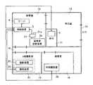
図1は、本実施形態における小規模診断システム1のシステム構成を示すものであり、図2は、小規模診断システム1を適用した場合の各装置の医療施設における配置例を示すものである。 FIG. 1 shows a system configuration of a small-
小規模診断システム1は、開業医やクリニック等の比較的小規模の医療施設に適用されるシステムであり、図1に示すように、画像生成装置2である超音波診断装置2a、内視鏡装置2b、CR装置2cと、制御装置3と、サーバ4と、レセプト用コンピュータ(以下、レセコンという。)5とから構成されており、各装置は、例えば図示しないスイッチングハブ等を介してLAN(Local Area Network)等の通信ネットワーク(以下単に「ネットワーク」という)6に接続されている。制御装置3は、医師の常駐場所である診察室に設けられたWS(ワークステーション)であることが好ましい。なお、この制御装置3として作動するWSが各画像生成装置2の起動や処理条件等を制御する構成としてもよい。 The small-
病院内の通信方式としては、一般的に、DICOM(Digital Image and Communications in Medicine)規格が用いられており、LAN接続された各装置間の通信では、DICOM MWM(Modality Worklist Management)やDICOM MPPS(Modality Performed Procedure Step)が用いられる。なお、本実施形態に適用可能な通信方式はこれに限定されない。 In general, DICOM (Digital Image and Communications in Medicine) standard is used as a communication method in a hospital, and DICOM MWM (Modality Worklist Management) or DICOM MPPS (DICOM MPPS) is used for communication between devices connected to a LAN. Modality Performed Procedure Step) is used. Note that the communication method applicable to this embodiment is not limited to this.
例えば、開業医やクリニック等のような小規模の医療施設においては、各装置は図2に示すように配置される。
すなわち、入口10を入ると患者の受付けを行う受付11と待合室12がある。受付11には窓口担当が配置され、当該担当は、来院した患者に対して、例えば、受付順に個々の患者を区別するための受付番号が印刷された受付番号札を付与する。また、受付11には、保険点数計算、会計計算等を行うレセコン5が設けられており、窓口担当は、患者の氏名を聞き取り、レセコン5に受付番号と患者氏名との対応付けを入力する。更に、窓口担当は、患者の診察終了後カルテ情報に基づき、レセコン5に保険点数請求に関する情報(以下、レセプト関連情報という。)の必要事項を入力する作業も行う。For example, in a small-scale medical facility such as a medical practitioner or a clinic, each device is arranged as shown in FIG.
That is, when entering the
待合室12の隣には、ドア等を隔てて医師が患者の診察、診断等を行う診察室13が設けられている。例えば診察室13内の診察用のデスク(図示せず)の上には、医師による診断のために、患者の診断対象部位を撮影した撮影画像、患者に対して行った検査(例えば、検体検査(血液検査、尿・便検査、組織片採取検査等)、心電図検査等)に関する検査情報、患者に対して投与した薬剤等に関する投薬情報を始めとする治療情報等を表示させる制御装置3と、撮影画像の画像データを保存する画像DB(Data Base)40を備えたサーバ4が配置されている。診察室13内にはまた、プライバシー等の観点から隔離された空間で行う必要性の低い超音波診断装置2aが設置されている。 Next to the
また、廊下14を隔てて診察室13の向かい側にはX線撮影を行うX線撮影室15が設けられている。X線撮影室15内には、撮影装置22と読取装置23とから構成されるCR装置2cが配設されている。さらに、X線撮影室15の隣には検査室16が設けられており、検査室16内には内視鏡装置2bが配設されている。 Further, an
以下、小規模診断システム1の各装置の構成について説明する。
画像生成装置2は、例えば、超音波診断装置2a、内視鏡装置2b、CR装置2c等の、患者の診断対象部位を被写体として撮影を行い、撮影した画像をデジタル変換して撮影画像の画像データ(撮影画像情報)を生成する画像生成手段(モダリティ)である。Hereinafter, the configuration of each device of the small-
For example, the
超音波診断装置2aは、超音波を出力する超音波プローブと、超音波プローブに接続され、超音波プローブで受信された音波(エコー信号)を内部組織の撮影画像の画像データに変換する電子装置とから構成されている(いずれも図示せず)。超音波診断装置2aは、超音波プローブから体内に超音波を送り、体内組織に反射した音波(エコー信号)を再び超音波プローブで受信して、このエコー信号に応じた撮影画像を電子装置によって生成するようになっている。 The ultrasonic
超音波診断装置2aには、アナログ信号からデジタル信号への変換等を行う変換手段(コンバータ)である変換装置21が接続されており、超音波診断装置2aは、変換装置21を介してネットワーク6に接続されている。このように変換装置21を介することにより、ネットワーク6に接続された他の外部機器の規格(例えば、通信プロトコル)等に合わない形式のデータが超音波診断装置2aから出力される場合でも適宜変換してネットワーク6に接続された外部機器との間でデータの送受信を行うことができる。 The ultrasonic
本実施の形態において、変換装置21は、DICOM規格に準じた形式で小規模診断システム1内の画像データを特定するためのUID(ユニークID)を画像データに付与する機能を備えている。UIDは、画像生成装置2の識別情報(以下、モダリティIDという。)、撮影日付及び時刻を示す数字等から構成される。なお、本実施の形態において、モダリティIDは画像生成装置2の種類を示す情報を含んで構成されているものとする。 In the present embodiment, the
変換装置21には、例えば、テンキー、キーボード、タッチパネル等で構成される入力操作部21aが設けられている。入力操作部21aの構成はここに示したものに限定されず、例えば、カードを差し込むことでカードに書き込まれた情報を読み取るカードリーダのようなものでもよい。入力操作部21aは、撮影対象である患者と対応付けられて設定された検索用ID(本実施の形態では受付番号)を入力するためのものであり、変換装置21は、入力操作部21aにより入力された検索用ID及び上述のUID等を撮影された撮影画像の画像データに付帯させる。 The
ここで検索用IDとは、撮影後に撮影画像を検索する際、撮影対象となった患者を識別する識別情報となるものであり、ここでは、受付けを行ったときに付与される受付番号とする。本実施の形態における小規模診断システム1では、予め患者に対する検査オーダー(撮影オーダー)を生成・発行せずに、患者の撮影を先行し、デジタル的な撮影画像データを生成後、医師が患者情報と撮影画像とを対応付けるシステムであるが、この対応付け時に使用されるのが検索用IDである。
入力操作部21aにより検索用IDとして受付番号を入力する場合に、例えば、受付11で付与された受付番号が「001」である患者を撮影する場合には、入力操作部21aから、患者に対応する検索用IDとして「001」を入力する。
開業医等においては、通常、1日あたりの来院数は10〜40人程度であり、受付順を示す受付番号の通し番号は2桁あれば充分で、入力操作部21aはこの2桁の数値が入力できればよく、安価なテンキーが好ましい。
なお、以下においては、検索用IDとして受付番号を用いる場合を例として説明するが、後述するように、検索用IDは、受付番号に限定されない。
なお、複数の患者を連続的に撮影する可能性がない場合(患者の区切りに充分な間がある場合)には、各画像に付帯されたモダリティID+撮影日付及び時刻で構成されたUIDに基づき、医師は容易に画像データと患者を対応付けることが可能である為、検索用IDの入力は必ずしも必要ではない。このケースにおいては、各画像生成装置2は、検索用IDの入力なしに、動作開始するよう設定される。Here, the search ID is identification information for identifying a patient to be imaged when searching for a captured image after imaging, and here is a reception number given when receiving is performed. . In the small-
When inputting a reception number as a search ID by the
In general practitioners, the number of visits per day is about 10 to 40, and it is sufficient that the serial number of the reception number indicating the reception order is two digits, and the
In the following, a case where a reception number is used as a search ID will be described as an example. However, as will be described later, the search ID is not limited to a reception number.
If there is no possibility of continuously photographing a plurality of patients (when there is a sufficient interval between patient separations), based on the UID composed of the modality ID attached to each image + imaging date and time Since the doctor can easily associate the image data with the patient, it is not always necessary to input the search ID. In this case, each
入力操作部21aから入力され撮影画像に付帯される情報は、検索用IDに限定されない。患者の氏名等、患者を識別する各種情報を入力操作部21aから入力するようにしてもよい。当該撮影が造影剤等を用いない単純撮影か、造影剤を用いた撮影か等の撮影の種類を特定する情報等を入力するようにしてもよい。入力された検索用IDその他の情報はヘッダ情報等の付帯情報として撮影画像の画像データに付帯され、画像データが外部機器に送信されるときにはこれらの情報も画像データと対応付けられて送信される。 The information input from the
内視鏡装置2bは、可撓性を有する管の先端部に小型の撮影装置が設けられたものであり(いずれも図示せず)、撮影装置は例えば光学レンズ等で構成される対物光学系と、対物光学系の結像位置に配置された撮像部と、LED(Light Emitting Diode)等で構成され撮像を行うために必要な照明を行う照明部とを備えている(いずれも図示せず)。撮像部は、例えばCCD(Charge Coupled Device)、CMOS(Complementary Metal-Oxide Semiconductor)等の固体撮像素子を備え、光が入射すると光の入射光量に応じた量の電気的な信号へと光電変換する。対物光学系は、照明部により照明された領域を光学レンズで集光し、撮像部が有する固体撮像素子に結像するように構成されており、固体撮像素子に入射した光が光電変換されることにより、電気信号として撮影画像の画像データが出力されるようになっている。 The
CR装置2cを構成する撮影装置22は、図示しない放射線源を有し、患者の診断対象部位に放射線を照射して静止画像を撮影する。撮影時には前記放射線源から照射される放射線の照射領域内に、例えば放射線エネルギーを蓄積する輝尽性蛍光体シートを備える放射線画像変換プレートが内蔵された放射線画像変換媒体(いずれも図示せず)が配置されるようになっており、放射線源からの照射放射線量に対する診断対象部位の放射線透過率分布に従った放射線量が放射線画像変換媒体に内設された輝尽性蛍光体シートの輝尽性蛍光体層に蓄積し、この輝尽性蛍光体層に診断対象部位の放射線画像情報を記録する。 The
読取装置23は、診断対象部位の放射線画像情報が記録された放射線画像変換媒体が装填されると、装置内に装填された放射線画像変換媒体の輝尽性蛍光体シートに励起光を照射し、これによりシートから発光される輝尽光を光電変換し、得られた画像信号をA/D変換して、撮影画像の画像データを生成するようになっている。
CR装置2cは撮影装置22と読取装置23とが一体化した一体型の装置であってもよい。When the radiographic image conversion medium in which the radiographic image information of the diagnostic target part is recorded is loaded, the
The
なお、図示はしないが、内視鏡装置2b、CR装置2cの読取装置23にも超音波診断装置2aにおける変換装置21の入力操作部21aと同様に撮影の際に画像データに検索用IDを入力するための入力操作部が設けられており、入力操作部から入力された検査IDを生成した撮影画像の画像データに付帯させるようになっている。また、内視鏡装置2b、CR装置2cの読取装置23においては、生成された画像データに上述のUIDを付与する機能が備えられており、この付与されたUIDも画像データに付帯させる。 Although not shown, the
制御装置3は、例えば診察室13に設置され、医師が画像等を表示させて読影診断等を行うためのワークステーションであり、一般的なPC(Personal Computer)に用いられるモニタ(表示部)よりも高精細のモニタを備えるものであってもよい。制御装置3は、図3に示すように、CPU31、RAM32、記憶部33、入力部34、表示部35、通信部36等を備えて構成されており、各部はバス37により接続されている。 The
CPU31は、記憶部33に記憶されているシステムプログラムや処理プログラム等の各種プログラムを読み出してRAM32に展開し、展開されたプログラムに従って後述する画像処理や患者情報と画像との対応付け処理、診療サマリ表示処理をはじめとする各種処理を実行する。 The
記憶部33は、HDD(Hard Disc)や半導体の不揮発性メモリ等により構成される。
記憶部33には、前述のように各種プログラムが記憶されているほか、特開H11−85950や特開2001−76141の明細書中に開示されているような撮影部位を識別するための部位識別パラメータ(撮影画像に現われた撮影対象の輪郭、形状等と撮影部位とを対応付けるルックアップテーブル等)及び識別された撮影部位に応じた画像処理を行う画像処理パラメータ(階調処理に用いる階調曲線を定義したルックアップテーブル、周波数処理の強調度等)等が記憶されている。The
In the
また、記憶部33は、画像生成装置2から送信された画像データ(付帯情報を含む)を一時的に保存する一時記憶部331を有している。 In addition, the
入力部34は、カーソルキー、数字入力キー、及び各種機能キー等を備えたキーボードと、マウス等のポインティングデバイスを備えて構成され、キーボードで押下操作されたキーの押下信号とマウスによる操作信号とを、入力信号としてCPU31に出力する。 The
表示部35は、例えば、CRT(Cathode Ray Tube)やLCD(Liquid Crystal Display)等のモニタを備えて構成されており、CPU31から入力される表示信号の指示に従って、各種画面を表示する。 The
通信部36は、ネットワークインターフェース等により構成され、スイッチングハブを介してネットワーク6に接続された外部機器との間でデータの送受信を行う。 The communication unit 36 includes a network interface or the like, and transmits / receives data to / from an external device connected to the
図1に戻り、サーバ4は、CPU、RAM、HDD等により構成される記憶部、ネットワーク6に接続された各装置との通信を制御する通信部(いずれも図示せず)等を備えて構成されたコンピュータである。サーバ4は、画像DB40を備えておりCPUと記憶部に記憶されたプログラムとの協働によるソフトウエア処理により、通信部を介して制御装置3から書込み指示された撮影画像の画像データ及びその付帯情報(患者情報及びUIDを含む情報)を対応付けて画像記憶手段としての画像DB40に格納するとともに、制御装置3からの要求に応じて画像DB40を検索して要求に応じた画像データ及びその付帯情報を読み出し、制御装置3に送信する。 Returning to FIG. 1, the server 4 includes a storage unit including a CPU, a RAM, an HDD, and the like, a communication unit (none of which is shown) that controls communication with each device connected to the
レセコン5は、CPU、RAM、HDD(Hard Disk)等により構成される記憶部、キーボードやマウス等により構成される入力部、CRTやLCD等により構成される表示部、ネットワーク6に接続された各装置との通信を制御する通信部(いずれも図示せず)等を備えて構成されたコンピュータである。レセコン5は、医師からの紙カルテ情報により窓口担当等の操作者により入力された、受付された患者に関するレセプト関連情報を記憶するレセプトDB50、患者に対して行った検査の検査情報を記憶する検査情報DB51を有している。 The
図4に、レセプトDB50のデータ格納例を示す。レセプトDB50は、来院した各患者のレセプト関連情報を格納するデータベースであり、図4に示すように、患者の受付日付を格納する「受付日付」項目、患者に付与した受付番号を格納する「受付番号」項目、患者情報(ここでは、患者氏名とする)を格納する「患者情報」項目、受付日付において当該患者に撮影された画像の枚数を格納する「撮影数」項目、造影剤を用いた撮影枚数を格納する「造影数」項目、撮影を行った画像生成装置2の種類を格納する「モダリティ」項目、撮影した部位情報を格納する「部位」項目、受付日付において患者に処方された薬剤の情報を格納する「投薬」項目、患者に対して行った検査の種別を示す情報を格納する「検査種別」項目、患者に対して行った検査を識別するための検査ID(検体検査の場合は、検体ID)を格納する「ID」項目、受付日付において医師が診断した傷病名を格納する「傷病名」項目、後述する制御装置3から入力されたコメントを格納する「コメント」項目、算出された保険点数を格納する「保険点数」項目等を有している。 FIG. 4 shows an example of data storage in the
検査情報DB51は、検査IDに対応付けて検査結果を示す検査情報を格納するデータベースである。 The
本実施の形態におけるレセプトDB50及び検査情報DB51は、レセプト情報記憶手段に相当するものである。本実施の形態においては、詳細な検査情報や、スキャナにより取り込んだ検査情報を格納可能とするため、レセプトDB50とは別の検査情報DB51に検査情報を格納し、レセプトDB50及び検査情報DB51を検査IDにより対応付けることにより、両者を関連付けて記憶しているが、検査情報はレセプト関連情報に含まれる情報であるため、レセプトDB50に「検査情報」項目を設け、検査結果を示す検査情報を「検査情報」項目に格納することとしてもよい。 The
レセコン5は、入力部より受付入力画面の表示が指示されると、CPUと記憶部に記憶されたプログラムとの協働によるソフトウエア処理により、表示部に図示しない受付入力画面を表示し、受付入力画面を介して入力部により受付情報(受付番号+患者情報)が入力されると、レセプトDB50に新しいレコードを追加し、現在日付を「受付日付」項目に、入力された受付番号を「受付番号」項目に、患者情報を「患者情報」項目に書込み、登録する。即ち、レセコン5における受付入力画面及び入力部により、受付手段、患者情報入力手段が実現される。また、入力部によりレセプト関連情報入力画面の表示部への表示が指示されると、表示部に、図示しないレセプト関連情報入力画面を表示し、このレセプト関連情報入力画面において、レセプト関連情報の入力対象となる患者の受付番号が入力され、更に、図4に示す各項目に対応する情報が入力されると、入力された情報を、レセプトDB50において本日の受付日付及び入力対象患者の受付番号を有するレコードの対応する項目に書込む。即ち、レセコン5におけるレセプト関連情報入力画面及び入力部により、レセプト関連情報入力手段が実現される。また、図示しない検査情報入力画面を介して入力部により検査ID及び検査情報が入力されると、入力された検査IDと検査情報とを対応付けて検査情報DB51に格納する。なお、レセコン5にスキャナを備える構成とし、検査情報の入力は、スキャナにより検査結果を示す用紙を読み取ることにより入力してもよい。また、レセコン5は、CPUと記憶部に記憶されたプログラムとの協働によるソフトウエア処理により、通信部を介して制御装置3から登録指示された情報をレセプトDB50の対応するレコードの対応する項目へ書込むとともに、制御装置3からの要求に応じてレセプトDB50を検索して要求に応じた情報を読み出し、制御装置3に送信(供給)する。
なお、本実施の形態においては、受付時に受付入力画面から受付番号及び患者情報を入力することとしたが、受付時には、受付番号のみを入力し、患者情報は、レセプト関連情報入力画面を介して入力することとしてもよい。即ち、レセプト関連情報入力手段が患者情報入力手段を含む構成としてもよい。また、患者情報のうち、患者氏名のみを受付入力画面から入力するものとし、その他の患者の性別、年齢、保険番号等の患者詳細情報はレセプト関連情報入力画面から入力するようにしてもよい。When the
In this embodiment, the reception number and the patient information are input from the reception input screen at the time of reception. However, at the time of reception, only the reception number is input, and the patient information is input via the receipt related information input screen. It is good also as inputting. That is, the receipt related information input means may include patient information input means. In addition, only the patient name in the patient information may be input from the reception input screen, and other patient detailed information such as the gender, age, and insurance number of other patients may be input from the receipt related information input screen.
次に、小規模診断システム1における、撮影画像及びレセプト関連情報生成の手順について説明する。 Next, a procedure for generating a captured image and receipt related information in the small-
まず、受付11において、来院した患者に受付番号札が付与され、患者氏名の聞き取りが行われる。次いで、レセコン5において、図示しない受付入力画面を介して入力部により受付番号及び患者氏名等の患者情報の入力が行われると、レセプトDB50に新規レコードが追加され、受付日付、受付番号及び患者情報が書き込まれる。 First, at the
受付番号が付与された患者が診察室13に移動すると、医師により問診が行われ、行うべき撮影、検査が決定される。 When the patient to whom the reception number is assigned moves to the
問診により患部の撮影が必要であると決定された場合には、医師や撮影技師等の撮影を行う撮影実施者は、患者を撮影を行う画像生成装置2(超音波診断装置2a、内視鏡装置2b、又はCR装置2c)の前に連れて行き、画像生成装置2において、入力操作部を介して、患者に付与された受付番号札に表示された検索用IDの入力を行い、その患者の診断対象部位を被写体として撮影を行い、撮影画像の画像データの生成を行う。例えば、画像生成装置2がCR装置2cの場合、読取装置23に備えられた入力部のテンキーから検索用IDの入力を行い、撮影装置22において撮影済みのカセッテを読取装置23にセットし、カセッテに記録された放射線画像の読み取りを行う。 When it is determined that the affected part needs to be photographed by the inquiry, the photographing person who performs photographing such as a doctor or a photographing engineer performs the image generation apparatus 2 (ultrasonic
画像生成装置2においては、入力操作部のテンキーが押下され、検索用IDが入力されると、撮影実施者の操作に応じて撮影及び画像データの生成が行われ、生成された画像データに入力された検索用IDやUIDが付帯されて制御装置3へ送信される。一の患者の画像を複数の撮影条件で複数枚撮影した場合、生成された全ての画像データに受付番号を示す検索用ID及びUIDが付帯され制御装置3へと送信される。なお、画像生成装置2においては検索用IDの入力がなければ、画像データの生成は行われないようになっている。なお、緊急時等、受付を経由していない患者を撮影する場合は、予め緊急割り込みを示す所定のコード、例えば、「99」のように、普段の診察時には現れないような番号を設定しておくと、通常のフローと同様に撮影後の画像データ抽出も可能となる。 In the
制御装置3においては、画像生成装置2から画像データ(付帯情報を含む)が受信されると、受信された画像データが一時記憶部331に記憶される。なお、一時記憶部331には、当該患者の画像データのみでなく、他の患者を撮影して得られた画像データであって、まだ診察されていない画像データが検索用IDと対応付けられた状態で次々と蓄積されていく。 In the
撮影や検査が終了すると、医師は患者の診察を行う。画像生成装置2により撮影が行われた場合は、以下のとおり、画像と患者の対応付け及び読影診断が行われる。 When the imaging and examination are completed, the doctor examines the patient. When imaging is performed by the
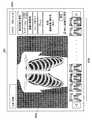
医師は、制御装置3の入力部34の操作により、表示部35に図示しない画像検索画面を表示させ、患者の受付番号札に記載された検索用IDを見て、入力部34を介して検索用IDの入力を行う。制御装置3においては、入力部34の操作に応じて画像検索画面を表示させ、入力部34を介して検索用IDの入力を受け付ける。画像検索画面が表示され、この画面から入力部34を介して検索用IDが入力されると、入力された検索用IDに対応する画像データが一時記憶部331から抽出され、抽出された画像データに階調処理や周波数強調処理等の画像処理が施され、画像処理済みの画像データを縮小したサムネイル画像が作成され、表示部35の撮影画像表示画面351に表示される。 By operating the
図5に、表示部35に表示される撮影画像表示画面351の表示画面例を示す。図6に示すように、撮影画像表示画面351は、抽出された画像を一覧表示するための画像表示欄351a〜351dを有している。画像表示欄351a〜351dの何れかが入力部34のマウス等により選択されると、選択された画像がライフサイズで単独表示される。医師はこの単独表示画像により、画像の詳細を観察し読影診断を行うことができる。また、当該画面の右上には、画像処理調整欄351eが設けられており、医師は、この画像処理調整欄351eをマウス等により操作することにより、濃度やコントラストの調整を行うことができる。各画像に対応して表示されているOKボタン351hを押下すると、表示されている画像を画像DB40に保存する画像として確定することができる。また、撮影画像表示画面351には、表示された撮影画像に対応付ける患者の患者氏名等の患者情報の入力を受け付ける患者情報入力欄351fが設けられている。医師は、この患者情報入力欄351fから患者情報の入力を行う。 FIG. 5 shows a display screen example of the captured
入力部34を介して、患者情報入力欄351fから当該患者に関する患者情報の入力が行われると、抽出された画像データの付帯情報に、この入力された患者情報が書込まれ、通信部36を介してサーバ4に送信され、画像DB40への書込み要求が行われる。画像DB40への画像データ書込み後、入力部34により撮影画像表示画面351の終了ボタンが押下されることにより、診断の終了が指示されると、サーバ4の画像DB40に書込まれた画像データ及び検索用IDが一時記憶部331から消去される。 When patient information related to the patient is input from the patient
診察室において患者の診察が終了すると、医師は、当該患者に対する所見(診断された傷病名)、当該患者に処方した薬剤を示す投薬情報、当該患者に対して行った撮影や検査に関する情報(撮影を行った装置の種類、撮影枚数、造影剤の有無、撮影部位、撮影方向、検査種別、検査ID等)を紙カルテに記録する。そして、紙カルテを受付11の窓口担当に回す。 When the examination of the patient is completed in the examination room, the doctor examines the patient (the name of the diagnosed wound), medication information indicating the medicine prescribed for the patient, and information on imaging and examination performed on the patient (imaging) And the like, the number of imaging, the number of imaging, the presence / absence of contrast medium, the imaging site, imaging direction, examination type, examination ID, etc.) are recorded in the paper chart. Then, the paper chart is sent to the
窓口担当は、レセコン5において、レセプト関連情報入力画面を表示させ、レセプト関連情報入力画面から、紙カルテの記載に基づきレセプト関連情報の入力を行う。入力された情報は、レセプトDB50に記憶される。 The contact person in charge displays a receipt related information input screen in the
また、窓口担当は、レセコン5において検査情報入力画面を表示させ、検査ID及び検査情報を入力する。レセコン5においては、検査情報入力画面から入力された検査情報が検査IDと対応付けられて検査情報DB51に記憶される。なお、外部の検査機関に検体検査を依頼するものについては、後日、検査機関から結果を受け取った際に、検査情報の入力を行う。 In addition, the person in charge displays the inspection information input screen in the
以上の手順により、小規模診断システム1においては、患者の診断対象部位を撮影した撮影画像が患者情報、撮影日付及び時刻情報と対応付けられてサーバ4の画像DB40に保存され、患者への投薬情報等の治療情報や検査情報を含むレセプト関連情報が患者情報及び受付日付(即ち、投薬や検査を行った日付)と対応付けてレセプトDB50に記憶される。また、検査情報が検査IDによりレセプト関連情報と対応付けられて検査情報DB51に記憶される。 According to the above procedure, in the small-
ここで、従来、医師が或る患者に対して実施した撮影や検査、投薬の全貌を把握したい場合、紙カルテにより診療記録を行っている医療施設においては、その患者の紙カルテをわざわざ棚から検索して情報を取得しなければならならず、不便であった。本実施の形態においては、制御装置3は、画像DB40に保存された撮影画像及びレセプトDB50に記憶されたレセプト関連情報等に基づいて、医師により指定された患者に対して実施した撮影の撮影画像、検査情報、投薬情報等を一覧にした画面(以下、診療サマリ画面という。)352を表示部35に表示する。 Here, when a doctor wants to grasp the whole picture of imaging, examination, and medication performed by a doctor on a patient in the past, in a medical facility where medical records are recorded using a paper chart, the patient's paper chart is bothered from the shelf. It was inconvenient because I had to search and get information. In the present embodiment, the
図6に、制御装置3において実行される診療サマリ表示処理、及びこれに応じて制御装置3、サーバ4、レセコン5において実行される診療サマリ表示シーケンスを示す。診療サマリ表示処理は、入力部34から診療サマリ表示指示が入力された際に実行される処理である。以下、診療サマリ表示シーケンスについて説明する。 FIG. 6 shows a medical summary display process executed in the
メニュー画面等から入力部34を介して診療サマリ表示指示が入力されると、表示部35に、診療サマリの表示対象となる患者(診断対象となる患者)の患者情報を指定するための患者指定画面が表示される。この表示部35に表示される患者指定画面と入力部34により患者情報指定手段が実現される。当該患者指定画面から入力部34を介して患者情報が入力されることにより診療サマリの表示対象となる患者が指定されると(ステップS1)、サーバ4に対して、入力された患者情報が送信され、当該患者情報に対応する画像データの取得要求がサーバ4に送信される(ステップS2)。 When a medical summary display instruction is input from the menu screen or the like via the
サーバ4において、制御装置3から患者情報が受信され、当該患者情報に対応する画像データの取得要求が受信されると、受信された患者情報に対応する画像データの画像DB40からの抽出が行われ(ステップS3)、抽出された画像データがその付帯情報とともに制御装置3に送信される(ステップS4)。 When the server 4 receives patient information from the
制御装置3においては、指定された患者情報に対応する画像データが付帯情報とともに取得されると、レセコン5に対して、ステップS1で指定された患者情報が送信され、当該患者に対応するレセプト関連情報の取得要求が送信される(ステップS5)。 In the
レセコン5において、制御装置3から患者情報が受信され、当該患者情報に対応するレセプト関連情報の取得要求が受信されると、受信された患者情報に対応するレセプト関連情報のレセプトDB50からの抽出が行われる(ステップS6)。抽出されたレセプト関連情報に検査IDが含まれている場合(ステップS7;YES)、検査情報DB51から当該検査IDにより識別される検査情報の抽出が行われる(ステップS8)。そして、抽出されたレセプト関連情報及び検査情報が制御装置3に送信される(ステップS9)。 When the patient information is received from the
制御装置3においては、指定された患者の患者情報に対応する画像データ、レセプト関連情報及び検査情報が受信されると、ステップS10及びS11の処理が実行され、表示手段が実現される。即ち、受信された画像データ、レセプト関連情報及び検査情報が患者情報に基づいて、診療サマリ画面用データが生成され、表示部35に診療サマリ画面352が表示される。そして、診療サマリ画面352上において表示された各種アイコンや操作ボタンの入力部34による操作に応じて、各種アイコンや操作ボタンに関連付けられた機能に応じた表示が行われる(ステップS11)。 In the
ステップS10においては、診療サマリ生成プログラムが読み出され、診療サマリ生成プログラムに従って、RAM32に診療サマリ画面用データが生成され、診療サマリ画面用データに基づいて診療サマリ画面352が表示される。例えば、RAM32に診療サマリ画面用データの格納領域が確保され、診療サマリの表示対象となっている患者の患者情報、及びデフォルトで予め設定されている期間、例えば、Nヶ月前(Nは正の整数)から現在日付までの時間軸が書込まれる。次いで、サーバ4から受信された画像データのうち、その付帯情報(UID)に含まれる撮影日付及び時刻が時間軸で表示されている期間内の各画像データについて、その画像の内容を簡略化して示すオブジェクトアイコン(サムネイル画像)が生成されてモダリティ種(例えば、CR、US(超音波診断装置)、内視鏡装置等)ごとに分類され、同一のモダリティで撮影された画像データのオブジェクトアイコンA1が時間軸に対応して画面横方向に並べて配置される。次いで、レセコン5から受信された検査情報のうち、検査日付(検査IDで対応付けられたレセプト関連情報の「受付日付」項目の日付)が時間軸で表示されている期間内の各検査情報について、その検査情報の内容を簡略化して示すオブジェクトアイコンA2が生成されて検査種別(例えば、心電図、血液検査、生理検査(尿検査、便検査、組織片検査)等)ごとに分類され、同一の検査種別のオブジェクトアイコンA2が時間軸に対応して画面横方向に並べて配置される。次いで、レセコン5から受信されたレセプト関連情報に含まれる投薬情報のうち、投薬日付(レセプト関連情報の「受付日付」項目の日付)が上述の時間軸で表示される期間内の各投薬情報について、投薬情報の内容を簡略化して示すオブジェクトアイコンA3が生成され、時間軸に対応して画面横方向に並べて配置される。各オブジェクトアイコンA1〜A3には、そのオブジェクトアイコンの基となった画像データ、検査情報又は投薬情報を詳細表示する機能が関連付けられる。また、レセコン5から受信されたレセプト関連情報のうち、受付日付が上述の時間軸の期間内の「傷病名」が時間軸に対応して画面横方向に並べて表示される。更に、各種機能が関連付けられた操作ボタンやアイコン等が生成され、所定の位置に配置される。その他、必要な表示が書込まれる。以上のようにして生成された診療画面データに基づいて、診療サマリ画面352が表示部35に表示される。 In step S10, a medical summary generation program is read, medical summary screen data is generated in the
オブジェクトアイコンA2は、検査情報の内容を簡略化して示すものであるが、例えば、上述の検査情報入力画面において、検査の結果の異常又は正常を入力する項目、異常値がある場合に異常値を入力する項目、異常値がある場合に前回も異常であったか否かを入力する項目、いつから異常なのかを入力する項目等を設けておき、これらを項目別に入力可能とし、検査情報DB51においてこれらの項目別に検査情報を格納しておくようにしておけば、これらの項目の中から予め設定された重要項目の内容をオブジェクトアイコンA2に表示することが可能となる。オブジェクトアイコンA2に表示する項目を入力部34により設定可能としてもよい。
オブジェクトアイコンA3についても、レセプトDB50の「投薬」項目を更に細分化した項目とし、投薬した薬剤名、1日分の分量、投薬期間を別個に格納可能としておくことで、診療サマリ画面352において、これらの情報を医師に見やすい態様で提供することが可能となる。The object icon A2 shows the contents of the inspection information in a simplified manner. For example, in the above-described inspection information input screen, an abnormal value is displayed when there is an item for inputting abnormality or normality of the inspection result or an abnormal value. Items to be input, items to input whether or not there was an abnormal value last time, items to input from when it was abnormal, etc. are provided, and these can be input for each item. If inspection information is stored for each item, the contents of important items set in advance among these items can be displayed on the object icon A2. Items to be displayed on the object icon A2 may be set by the
Also for the object icon A3, the “medicine” item of the
図7に、ステップS10で表示される診療サマリ画面352の好適な一例を示す。図 7に示すように、診療サマリ画面352は、画面上部に患者情報エリア352a、時間軸エリア352bを有し、これらの下方に診療サマリ表示エリア352cを有している。患者情報エリア352aには、診療サマリ画面352の表示対象となっている患者の患者情報が表示されている。時間軸表示エリア352bには、デフォルトで予め設定されている期間、例えば、Nヶ月前から現在日付までの時間軸が表示されている。診療サマリ表示エリア352cには、表示された時間軸の期間内に同一種類のモダリティにより撮影された画像データを示すオブジェクトアイコンA1、表示された時間軸の期間内に検査された同一の検査項目の検査情報を示すオブジェクトアイコンA2、表示された時間軸の期間内の投薬情報を示すオブジェクトアイコンA3、医師により診断された傷病名がそれぞれ時間軸に対応して画面横方向に並べて表示されている。医師は、このオブジェクトアイコンA1〜A3により、患者に対して撮影された撮影画像、患者に対して行われた検査の検査情報、患者に対して行われた治療の治療情報を容易に把握することができる。 FIG. 7 shows a preferred example of the medical
診療サマリ表示エリア352cに表示すべき情報が多く、一画面上に表示不可能である場合にはスクロールボタン(上スクロールボタン352d、下スクロールボタン352e)が表示され、入力部34による各スクロールボタンの押下操作に応じて診療サマリ表示エリア352cの情報がスクロール表示される。これにより、表示されていない情報を表示させることができる。例えば、図7(a)に示す診療サマリ画面352において、入力部34により下スクロールボタン352eを押下操作すると、診療サマリ表示エリア352cの情報が下にスクロールされるので、図7(b)に示すように、検査情報や投薬情報を表示させることができる。 When there is a lot of information to be displayed in the medical
また、診療サマリ画面352には、時間軸の表示スケール及び表示時期の変更を指示するためのスケール/時期変更エリア352fが表示される。スケール/時期変更エリア352fは、スケール/時期選択エリア、左矢印ボタン及び右矢印ボタンを有する。これらは、入力部34との協働により、表示画面上に表示する時間軸の期間を設定する表示期間設定手段として機能するものである。入力部34による、スケール/時期選択エリアにおけるスケール又は表示時期(時期)の選択操作に応じて、左矢印ボタン及び右矢印ボタンの機能が、表示スケールの変更又は表示時期の変更に切り替えられる。例えば、入力部34により「スケール」が選択されると、左矢印ボタン及び右矢印ボタンが時間軸の表示スケールの変更指示の入力ボタンに切り替えられ、その後の入力部34による左矢印ボタンの押下操作に応じて、時間軸の表示スケールが縮小され、右矢印ボタンの押下操作に応じて、時間軸の表示スケールが拡大される。入力部34により「時期」が選択されると、左矢印ボタン及び右矢印ボタンが時間軸の表示時期の変更指示の入力ボタンに切り替えられ、その後の入力部34による左矢印ボタンの押下操作に応じて、時間軸の表示時期が過去側に、右矢印ボタンの押下操作に応じて、時間軸の表示時期が現在側に変更される。これに応じて、表示されている時間軸の範囲内の画像データ、検査情報、投薬情報が抽出され、抽出された情報に基づきオブジェクトアイコンA1〜A3が作成され、時間軸に対応する位置に表示される。また、マウスにより時間軸上の一点が指定されると、時間軸において指定された点を含む年月の1ヶ月間が時間軸として表示され、指定された1ヶ月間の画像データ、検査情報、投薬情報が時間軸に対応して表示される。なお、オブジェクトアイコンA3により示される治療情報ついては、図7(b)に示すように、治療(投薬)期間を時間軸に対応させて表示させることが好ましい。また、各オブジェクトアイコンは、時間軸スケールの設定にあわせて、一覧表示時に見えやすいようにサイズを可変とすることが好ましい。 The medical
また、診療サマリ画面352には、時間軸上に基準時期を設定するための矢印アイコン352gが表示され、矢印アイコン352gの矢印により示される時間軸上の時期が基準時期に設定される。入力部34のマウス等により矢印アイコン352gが画面左右方向にドラッグされると、時間軸上の基準時期がドラッグ操作に応じて変更される。即ち、矢印アイコン352gの入力部34による操作により時間軸上に基準時期を設定する基準時期設定手段が実現される。図7(a)(b)に示すように、矢印アイコン352gにより指定された基準時期は点線により画面全体に渡って表示されるので、医師は、この基準時期前後で患者の病状がどのように変化したかを把握しやすくなる。例えば、薬剤の処方変更を行った時期を基準時期に設定すれば、医師は、基準時期前後の画像や検査情報の比較により、薬剤の処方変更前後での治療効果を容易に把握することが可能となる。なお、マウスにより矢印アイコンがクリックされると、コメント記入欄が表示され、基準時期に関するコメントが入力可能となる。入力部34によりコメント記入欄からコメントが入力されると、矢印アイコンにより指定された日付に対応するレセプトDB50のレセプト関連情報のコメント項目に入力されたコメント情報が書込まれ、以降にこの日付に対応する位置に矢印アイコンが設定された場合には、矢印アイコン352g近辺にコメントが表示される。 In addition, on the
診療サマリ表示エリア352cに表示されたオブジェクトアイコンA1の何れか一つがアイコン指定手段としての入力部34により指定されると、指定されたオブジェクトアイコンが示す画像を詳細表示する詳細画面353に表示部35の表示が切り替え制御される。 When any one of the object icons A1 displayed in the medical care
図8に、詳細画面353の一例を示す。詳細画面353は、診療サマリ画面352において指定された画像を表示する画像表示エリア353a、当該患者において同一モダリティで撮影された画像のサムネイル画像を撮影順に並べて表示する撮影順表示エリア353b、各種操作ボタン、診療サマリ画面352で指定された基準時期に対して入力されたコメントが表示されるコメント表示欄353cを有している。当該詳細画面353において、入力部34により「部位別表示選択」ボタンが押下されると、この患者で撮影された部位が一覧表示され、一覧表示から部位が選択されると、選択された部位の撮影画像のみが詳細画面353に表示される。入力部34により「アノテーション」ボタンが押下されると、矢印、塗りつぶし等を含む各種アノテーションの入力が可能となる。入力部34により「ON/OFF」ボタンが押下されると、アノテーションの表示/非表示が切り替えられる。入力部34により「画像比較画面」ボタンが押下されると、画像比較画面354(図9参照)に表示部35の表示が切り替え制御される。「シェーマ出力」ボタンが押下されると、制御装置3が電子カルテ情報を格納する電子カルテDBに接続されているときに、画像表示エリア353aに表示された画像やアノテーションを指定された電子カルテに貼り付ける処理に移行される。「プリント出力」ボタンが押下されると、画像表示エリア353aに表示された画像が出力される。その他、各種画像処理(拡大/縮小、回転/反転、階調調整、濃度調整を行うための操作ボタンが押下されると、押下操作に応じた処理が画像表示エリア353aに表示された画像データに施される。 FIG. 8 shows an example of the
図9(a)に、画像比較画面354の一例を示す。画像比較画面354においては、比較画像表示エリア354aに、診療サマリ画面352において矢印アイコン352gで指定された基準時期に撮影された基準画像と、診療サマリ画面352において指定されたオブジェクトアイコンA1に対応する撮影画像とが並べて表示される。これにより、医師は、基準画像と所望の時期の画像とを容易に比較することが可能となり、所望の時期からの患者の治癒動向を容易に把握することが可能となる。基準画像と比較する画像は、撮影画像下部に表示された矢印ボタン354c又は354dの押下、或いは撮影順に表示されたサムネイル画像からの選択により変更することができる。画像比較画面354には、詳細画面353に表示されたのと同様の各種操作ボタンの他、「画像フォーマット」ボタンが表示されている。入力部34によりこの「画像フォーマット」ボタンが押下されると、基準画像と比較する画像の枚数を設定するエリアがポップアップ表示され、当該エリアから設定された枚数の比較画像の比較画像表示エリア354aへの表示が可能となる。例えば、比較画像の枚数が3枚に設定されると、図9(b)に示す画像比較画面354が表示される。なお、比較画像表示エリア354aにおいて、比較画像と基準画像は撮影順に並べて表示される。 FIG. 9A shows an example of the
なお、診療サマリ画面352において、入力部34により図7に示す虫ピンアイコン352hを押下してから画像のオブジェクトアイコンA1を選択操作すると、選択されたオブジェクトアイコンA1に対応する画像を比較候補画像として設定しておくことができる。画像比較画面354においては、撮影順表示エリア354bに比較候補画像のサムネイル画像のみが撮影順に表示され、余分なサムネイル画像は表示されないので、比較画像表示エリア354aに基準画像と並べて表示する画像をより容易に選択することが可能となる。 Note that, when the object icon A1 of the image is selected and operated after the
診療サマリ画面352の診療サマリ表示エリア352cに表示されたオブジェクトアイコンA2の何れか一つがアイコン指定手段としての入力部34により指定されると、指定されたオブジェクトアイコンが示す検査情報を詳細表示する検査情報詳細画面(図示せず)に表示部35の表示が切り替え制御される。検査情報詳細画面においては、詳細画面353と同様に、指定されたオブジェクトアイコンA2が示す検査情報の詳細情報とともに、基準時期の検査情報が表示される。これにより、医師は基準時期の検査結果と所望の時期の検査結果とを容易に比較することが可能となる。 When any one of the object icons A2 displayed in the medical care
診療サマリ画面352の診療サマリ表示エリア352cに表示されたオブジェクトアイコンA3の何れか一つがアイコン指定手段としての入力部34により指定されると、指定されたオブジェクトアイコンが示す投薬情報を詳細表示する投薬情報詳細画面(図示せず)に表示部35の表示が切り替え制御される。投薬情報詳細画面においては、詳細画面353と同様に、指定されたオブジェクトアイコンが示す投薬情報の詳細情報とともに、基準時期の投薬情報が表示される。これにより、医師は基準時期の投薬結果と所望の時期の投薬結果とを容易に比較することが可能となる。 When any one of the object icons A3 displayed in the medical care
なお、診療サマリ画面352において、医師がまだ患者に説明していない検査情報のオブジェクトアイコンA2には、医師が患者に当該検査の結果をまだ説明していないことを識別可能とするための識別マークを付して表示することが好ましい。例えば、オブジェクトアイコンA2が入力部34により指定されると、検査情報の詳細を表示部35の表示画面上に表示することができるので、入力部34により一度も指定されたことのないオブジェクトアイコンA2については識別マークを付し、入力部34により指定され、そのオブジェクトアイコンA2に対応する検査情報の詳細情報が表示された時点で、患者への説明がなされたとみなしてそのオブジェクトアイコンA2に対する識別マークを削除する。入力部34によりオブジェクトアイコンA2が指定されたことのある検査情報であるか否かは、入力部34によりオブジェクトアイコンA2が指定された際に、指定されたオブジェクトアイコンA2に対応する検査情報の検査IDと説明済みであることを示す情報を制御装置3からレセコン5に送信し、検査情報DB51の当該検査IDにより識別される検査情報に対応付けて記憶しておき、診療サマリ画面352を表示する際には、説明済みであることを示す情報が対応していない検査情報に基づいて、上述の識別マークを付与するようにすればよい。 In the medical
以上説明したように、制御装置3によれば、医師により指定された患者情報に対応する画像データ及び付帯情報をサーバ4の画像DB40から取得するとともに、当該患者情報に対応する検査情報及び治療情報を含むレセプト関連情報をレセコン5から取得して、取得した撮影画像、検査情報及び治療情報に基づいて、医師により指定された患者の撮影画像、検査情報及び治療情報を時系列的に一覧的に表示する診療サマリ画面352を表示する。 As described above, according to the
従って、医師に電子カルテのような所見の入力操作作業等の負担を強いることなく、患者を指定するだけの簡単な入力操作で、小規模施設ならではの患者との関係にある(かかりつけ医的で、個々の患者と近しい関係にある)医師は、対象患者に対する撮影画像、検査情報、治療情報の全貌を把握することが可能となる。診療サマリ画面352においては、撮影画像、検査情報、治療情報が時間軸に対応させて時系列的に表示されるので、医師は、患者の経時的な治癒動向を容易に把握することが可能となる。撮影画像、検査情報、治療情報の詳細を閲覧したい場合には、診療サマリ画面352に表示されたオブジェクトアイコンA1〜A3の何れかを入力部34により指定するだけでその詳細情報を表示することができるので、容易な入力操作で、診断を容易に、正確に行うことが可能となる。また、紙カルテ運用の小規模施設における既存の設備であっても、画像生成装置2を備えていれば、撮影画像を患者情報と対応付けてデータベース等に記憶しており、また、患者の保険点数算出用に患者情報と対応付けて投薬情報や検査情報をコンピュータで入力し、保存しているので、既存の設備から少ない改造規模で、患者の撮影、検査、治療情報を容易に検索可能な、使い勝手のよい小規模診断システムを実現することができる。 Therefore, it does not impose a burden on the input operation such as an electronic medical record for a doctor, and it is a simple input operation that only designates a patient and has a relationship with a patient unique to a small-scale facility. A doctor who has a close relationship with an individual patient can grasp the whole picture of the captured image, examination information, and treatment information for the target patient. On the medical
なお、上記実施の形態における記述内容は、本発明に係る小規模診断システム1の好適な一例であり、これに限定されるものではない。 In addition, the description content in the said embodiment is a suitable example of the small-
例えば、上記実施の形態においては、診療サマリ画面352に、指定された患者の撮影画像、検査情報、治療情報を一覧にして表示する場合を例にとり説明したが、必ずしもこれらの全てを表示する必要はなく、入力部34を介して、診療サマリ画面352に表示する情報を設定可能としてもよい。例えば、撮影画像と検査情報とを診療サマリ画面352に表示させるようにしてもよいし、撮影画像と治療情報とを診療サマリ画面352に表示させるようにしてもよい。また、撮影画像のうち、診療サマリ画面352の表示対象とするモダリティを設定可能としてもよい。 For example, in the above-described embodiment, a case has been described in which a list of captured images, examination information, and treatment information of a specified patient is displayed on the medical
また、制御装置3を電子カルテ装置と接続可能な構成とし、電子カルテ装置の情報を診療サマリ画面352に表示させるようにしてもよい。 Further, the
その他、本発明が本実施の形態に限定されず、適宜変更可能であることはいうまでもない。 In addition, it goes without saying that the present invention is not limited to the present embodiment and can be appropriately changed.
1 小規模診断システム
2 画像生成装置
2a 超音波診断装置
2b 内視鏡装置
2c CR装置
3 制御装置
4 サーバ
40 画像DB
5 レセコン
50 レセプトDB
51 検査情報DB
6 ネットワーク
21 変換装置
31 CPU
32 RAM
33 記憶部
331 一時記憶部
34 入力部
35 表示部
351 撮影画像表示画面
352 診療サマリ画面
353 詳細画面
354 画像比較画面
36 通信部
37 バスDESCRIPTION OF
5 Reckon 50 Receipt DB
51 Inspection information DB
6
32 RAM
33
Claims (4)
Translated fromJapanese前記受付手段で登録された前記個々の患者を区別する情報及び受付日付情報に対応付けて患者情報を入力する患者情報入力手段と、
患者の撮影画像情報を生成する少なくとも一つの画像生成手段と、
前記画像生成手段により生成された撮影画像情報と、当該撮影の対象患者に対応する患者情報及び当該撮影画像情報の撮影日付情報とを対応付けて記憶する画像記憶手段と、
前記受付手段により受け付けられた前記個々の患者を区別する情報及び受付日付情報に対応する、電子化された検査情報、及び/又は治療情報を含むレセプト関連情報を入力するレセプト関連情報入力手段と、
前記個々の患者を区別する情報及び前記受付日付情報に基づいて、前記入力された患者情報及びレセプト関連情報を対応付けて記憶するレセプト情報記憶手段と、
診断対象の患者の患者情報に対応付けて前記画像記憶手段に記憶された前記撮影画像情報及び当該撮影画像情報の撮影日付情報を取得するとともに、当該患者情報に対応付けて前記レセプト情報記憶手段に記憶された前記検査情報及び/又は前記治療情報をその受付日付情報とともに取得する制御装置と、を備え、
前記制御装置は、前記取得された前記撮影画像情報と、前記検査情報及び/又は前記治療情報とを対応付け、前記患者情報とともに時系列的に画面上に一覧表示する表示手段を有することを特徴とする診断システム。An accepting means for accepting a patient and performing registration processing together with information for distinguishing individual patients and acceptance date information;
Patient information input means for inputting patient information in association with information and reception date information for distinguishing the individual patients registered by the reception means;
At least one image generating means for generating captured image information of the patient;
Image storage means for storing the captured image information generated by the image generation means, the patient information corresponding to the patient to be imaged and the imaging date information of the captured image information in association with each other;
Receipt related information input means for inputting electronically related examination information and / or reception related information including treatment information corresponding to the information for distinguishing the individual patient received by the receiving means and the reception date information;
Based on the information for distinguishing the individual patients and the reception date information, a receipt information storage means for storing the input patient information and the receipt related information in association with each other;
The captured image information stored in the image storage unit in association with the patient information of the patient to be diagnosed and the shooting date information of the captured image information are acquired, and in the receipt information storage unit in association with the patient information. A control device that acquires the stored examination information and / or the treatment information together with the reception date information,
The control device includes display means for associating the acquired captured image information with the examination information and / or the treatment information and displaying a list on the screen in time series together with the patient information. Diagnostic system.
前記画像記憶手段は、前記画像生成手段により生成された撮影画像情報と、当該撮影の対象患者の患者情報、当該撮影画像情報の撮影日付情報及び前記画像生成手段の種類を示す情報とを対応付けて記憶し、
前記制御装置の表示手段は、前記画像生成手段の種類毎に、前記撮影画像情報を一覧表示することを特徴とする請求項1又は2に記載の診断システム。A plurality of types of the image generating means;
The image storage means associates the captured image information generated by the image generation means with patient information of the subject patient to be imaged, imaging date information of the captured image information, and information indicating the type of the image generation means. Remember,
The diagnostic system according to claim 1, wherein the display unit of the control device displays a list of the captured image information for each type of the image generation unit.
Priority Applications (5)
| Application Number | Priority Date | Filing Date | Title |
|---|---|---|---|
| JP2006056448AJP2007233841A (en) | 2006-03-02 | 2006-03-02 | Diagnostic system |
| EP07708043AEP1990765A4 (en) | 2006-03-02 | 2007-02-05 | Medical image system |
| CNA2007800070680ACN101395630A (en) | 2006-03-02 | 2007-02-05 | Medical image system |
| US12/281,096US20090054755A1 (en) | 2006-03-02 | 2007-02-05 | Medical imaging system |
| PCT/JP2007/051925WO2007099735A1 (en) | 2006-03-02 | 2007-02-05 | Medical image system |
Applications Claiming Priority (1)
| Application Number | Priority Date | Filing Date | Title |
|---|---|---|---|
| JP2006056448AJP2007233841A (en) | 2006-03-02 | 2006-03-02 | Diagnostic system |
Publications (1)
| Publication Number | Publication Date |
|---|---|
| JP2007233841Atrue JP2007233841A (en) | 2007-09-13 |
Family
ID=38554355
Family Applications (1)
| Application Number | Title | Priority Date | Filing Date |
|---|---|---|---|
| JP2006056448APendingJP2007233841A (en) | 2006-03-02 | 2006-03-02 | Diagnostic system |
Country Status (2)
| Country | Link |
|---|---|
| JP (1) | JP2007233841A (en) |
| CN (1) | CN101395630A (en) |
Cited By (33)
| Publication number | Priority date | Publication date | Assignee | Title |
|---|---|---|---|---|
| JP2009288880A (en)* | 2008-05-27 | 2009-12-10 | Toshiba Corp | Health management support device and health examination system |
| JP2010033476A (en)* | 2008-07-31 | 2010-02-12 | Fujitsu Ltd | Diagnostic information display device, diagnostic information display method and program |
| JP2010075403A (en)* | 2008-09-25 | 2010-04-08 | Canon Inc | Information processing device and method of controlling the same, data processing system |
| KR100969510B1 (en) | 2010-05-31 | 2010-07-09 | 주식회사 인트로메딕 | Apparatus and method of processing medical data by client |
| WO2011122402A1 (en)* | 2010-03-31 | 2011-10-06 | 株式会社 日立メディコ | Inspection information display device and method |
| WO2011122401A1 (en)* | 2010-03-31 | 2011-10-06 | 株式会社 日立メディコ | Inspection information display device and method |
| JP2011233135A (en)* | 2010-03-31 | 2011-11-17 | Sugiura Gijyutushi Jimusyo | Medical examination supporting apparatus |
| JP2011233134A (en)* | 2010-03-31 | 2011-11-17 | Sugiura Gijyutushi Jimusyo | Medical examination supporting device |
| WO2012141330A1 (en)* | 2011-04-14 | 2012-10-18 | 株式会社 東芝 | Medical information system and medical information display device |
| JP2013003658A (en)* | 2011-06-13 | 2013-01-07 | Hitachi Ltd | Medical support system |
| JP2013182394A (en)* | 2012-03-01 | 2013-09-12 | Yokogawa Electric Corp | Medical information management system |
| JP2013228968A (en)* | 2012-04-27 | 2013-11-07 | Ge Medical Systems Global Technology Co Llc | Display device and display control program for the same |
| JP2013242745A (en)* | 2012-05-22 | 2013-12-05 | Astrostage Inc | Diagnosis data integrated management system and disease diagnosis cooperation system in cooperation with diagnosis data integrated management system |
| JP2014045862A (en)* | 2012-08-30 | 2014-03-17 | Canon Inc | Optical tomographic imaging apparatus, image processor and display method of optical tomographic image |
| WO2015045947A1 (en)* | 2013-09-27 | 2015-04-02 | 富士フイルム株式会社 | Medical assistance device, control method for medical assistance device, medical assistance program, and medical assistance system |
| JP2015111383A (en)* | 2013-12-06 | 2015-06-18 | 株式会社東芝 | Medical data management system |
| JP2015167637A (en)* | 2014-03-05 | 2015-09-28 | 株式会社東芝 | Medical image processing apparatus and medical image diagnostic apparatus |
| JP2015228103A (en)* | 2014-05-30 | 2015-12-17 | 株式会社東芝 | Medical information display system |
| WO2016175528A1 (en)* | 2015-04-30 | 2016-11-03 | 주식회사 티플러스 | Device for automatically selecting key image from medical images |
| JP2017058936A (en)* | 2015-09-16 | 2017-03-23 | 富士ゼロックス株式会社 | Medical document management device, medical document management system, and program |
| JP2018533123A (en)* | 2015-09-10 | 2018-11-08 | エフ.ホフマン−ラ ロシュ アーゲーF. Hoffmann−La Roche Aktiengesellschaft | An information science platform for integrated clinical care |
| JP2019003230A (en)* | 2017-06-09 | 2019-01-10 | キヤノン株式会社 | Information processing device, information processing method and program |
| JP2019040367A (en)* | 2017-08-24 | 2019-03-14 | キヤノンメディカルシステムズ株式会社 | Medical information processing system |
| JP2019106143A (en)* | 2017-12-14 | 2019-06-27 | キヤノンメディカルシステムズ株式会社 | Medical information processing device and medical information processing method |
| JP2019203715A (en)* | 2018-05-21 | 2019-11-28 | エスペック株式会社 | Environment formation device |
| CN110998645A (en)* | 2017-08-10 | 2020-04-10 | 奥林巴斯株式会社 | Observation system and information management method |
| JP2020102128A (en)* | 2018-12-25 | 2020-07-02 | 株式会社OPExPARK | Information sharing system |
| US10918351B2 (en) | 2016-08-19 | 2021-02-16 | Konica Minolta, Inc. | Radiographic-image processing apparatus |
| US20210151151A1 (en)* | 2018-07-27 | 2021-05-20 | Hd Junction, Inc | Medical information query and input system, medical information query and input method, and program for performing same |
| JP2021165924A (en)* | 2020-04-07 | 2021-10-14 | 独立行政法人国立病院機構 | Inspection record grasping device and ultrasonic inspection device equipped with this |
| JP2022068035A (en)* | 2020-10-21 | 2022-05-09 | キヤノンメディカルシステムズ株式会社 | Report confirmation support system, report confirmation support method, and report confirmation support program |
| JP2022136238A (en)* | 2018-07-27 | 2022-09-15 | エイチディー・ジャンクション・インコーポレイテッド | Medical information query and input system, medical information query and input method, and program for implementing same |
| JP2023503966A (en)* | 2019-11-27 | 2023-02-01 | フジフィルム メディカル システムズ ユー.エス.エー,インコーポレイテッド | Methods and systems for displaying medical examination relevance and timelines |
Families Citing this family (8)
| Publication number | Priority date | Publication date | Assignee | Title |
|---|---|---|---|---|
| US9117008B2 (en)* | 2010-08-31 | 2015-08-25 | Canon Kabushiki Kaisha | Display apparatus and display method for displaying the radiographing range of a human body to be examined |
| KR101644466B1 (en)* | 2012-08-30 | 2016-08-01 | 캐논 가부시끼가이샤 | Information processing apparatus and method |
| JP2014123181A (en)* | 2012-12-20 | 2014-07-03 | Fuji Xerox Co Ltd | Program, and medical treatment recording and display device |
| EP3132367A1 (en)* | 2014-04-17 | 2017-02-22 | Koninklijke Philips N.V. | Method and system for visualization of patient history |
| CN105988748B (en)* | 2015-02-16 | 2019-01-04 | 株式会社理光 | Medical image forms device and medical image forms system |
| CN105989231B (en)* | 2015-02-16 | 2019-03-12 | 株式会社理光 | Medical image forms device and medical image forms system |
| CN108010570A (en)* | 2017-11-30 | 2018-05-08 | 上海联影医疗科技有限公司 | A kind of medical image processing method, medical image processing equipment and system |
| CN109450985B (en)* | 2018-10-17 | 2021-09-21 | 中电万维信息技术有限责任公司 | High-performance Web image loading and displaying system based on Html5 |
Citations (5)
| Publication number | Priority date | Publication date | Assignee | Title |
|---|---|---|---|---|
| JPH07160787A (en)* | 1993-12-07 | 1995-06-23 | Daikin Ind Ltd | Medical image data processing method and apparatus thereof |
| JPH10187743A (en)* | 1996-12-26 | 1998-07-21 | Sharp Corp | Data display method |
| JPH11342112A (en)* | 1998-06-03 | 1999-12-14 | Green Joho Systems Kk | Data display device for medical care support |
| JP2001076078A (en)* | 1999-09-07 | 2001-03-23 | Yasuo Kumagai | Medical information reference system, medical information reference method and medical information preserving method |
| JP2001118008A (en)* | 1999-10-15 | 2001-04-27 | Hitachi Ltd | Electronic medical record system |
- 2006
- 2006-03-02JPJP2006056448Apatent/JP2007233841A/enactivePending
- 2007
- 2007-02-05CNCNA2007800070680Apatent/CN101395630A/enactivePending
Patent Citations (5)
| Publication number | Priority date | Publication date | Assignee | Title |
|---|---|---|---|---|
| JPH07160787A (en)* | 1993-12-07 | 1995-06-23 | Daikin Ind Ltd | Medical image data processing method and apparatus thereof |
| JPH10187743A (en)* | 1996-12-26 | 1998-07-21 | Sharp Corp | Data display method |
| JPH11342112A (en)* | 1998-06-03 | 1999-12-14 | Green Joho Systems Kk | Data display device for medical care support |
| JP2001076078A (en)* | 1999-09-07 | 2001-03-23 | Yasuo Kumagai | Medical information reference system, medical information reference method and medical information preserving method |
| JP2001118008A (en)* | 1999-10-15 | 2001-04-27 | Hitachi Ltd | Electronic medical record system |
Cited By (47)
| Publication number | Priority date | Publication date | Assignee | Title |
|---|---|---|---|---|
| JP2009288880A (en)* | 2008-05-27 | 2009-12-10 | Toshiba Corp | Health management support device and health examination system |
| JP2010033476A (en)* | 2008-07-31 | 2010-02-12 | Fujitsu Ltd | Diagnostic information display device, diagnostic information display method and program |
| JP2010075403A (en)* | 2008-09-25 | 2010-04-08 | Canon Inc | Information processing device and method of controlling the same, data processing system |
| JPWO2011122402A1 (en)* | 2010-03-31 | 2013-07-08 | 株式会社日立メディコ | Inspection information display apparatus and method |
| WO2011122402A1 (en)* | 2010-03-31 | 2011-10-06 | 株式会社 日立メディコ | Inspection information display device and method |
| WO2011122401A1 (en)* | 2010-03-31 | 2011-10-06 | 株式会社 日立メディコ | Inspection information display device and method |
| JP2011233135A (en)* | 2010-03-31 | 2011-11-17 | Sugiura Gijyutushi Jimusyo | Medical examination supporting apparatus |
| JP2011233134A (en)* | 2010-03-31 | 2011-11-17 | Sugiura Gijyutushi Jimusyo | Medical examination supporting device |
| US8929627B2 (en) | 2010-03-31 | 2015-01-06 | Hitachi Medical Corporation | Examination information display device and method |
| JPWO2011122401A1 (en)* | 2010-03-31 | 2013-07-08 | 株式会社日立メディコ | Inspection information display apparatus and method |
| KR100969510B1 (en) | 2010-05-31 | 2010-07-09 | 주식회사 인트로메딕 | Apparatus and method of processing medical data by client |
| WO2012141330A1 (en)* | 2011-04-14 | 2012-10-18 | 株式会社 東芝 | Medical information system and medical information display device |
| JP2013003658A (en)* | 2011-06-13 | 2013-01-07 | Hitachi Ltd | Medical support system |
| JP2013182394A (en)* | 2012-03-01 | 2013-09-12 | Yokogawa Electric Corp | Medical information management system |
| JP2013228968A (en)* | 2012-04-27 | 2013-11-07 | Ge Medical Systems Global Technology Co Llc | Display device and display control program for the same |
| JP2013242745A (en)* | 2012-05-22 | 2013-12-05 | Astrostage Inc | Diagnosis data integrated management system and disease diagnosis cooperation system in cooperation with diagnosis data integrated management system |
| JP2014045862A (en)* | 2012-08-30 | 2014-03-17 | Canon Inc | Optical tomographic imaging apparatus, image processor and display method of optical tomographic image |
| JPWO2015045947A1 (en)* | 2013-09-27 | 2017-03-09 | 富士フイルム株式会社 | MEDICAL SUPPORT DEVICE, MEDICAL SUPPORT DEVICE CONTROL METHOD, MEDICAL SUPPORT PROGRAM, AND MEDICAL SUPPORT SYSTEM |
| WO2015045947A1 (en)* | 2013-09-27 | 2015-04-02 | 富士フイルム株式会社 | Medical assistance device, control method for medical assistance device, medical assistance program, and medical assistance system |
| JP2015111383A (en)* | 2013-12-06 | 2015-06-18 | 株式会社東芝 | Medical data management system |
| JP2015167637A (en)* | 2014-03-05 | 2015-09-28 | 株式会社東芝 | Medical image processing apparatus and medical image diagnostic apparatus |
| JP2015228103A (en)* | 2014-05-30 | 2015-12-17 | 株式会社東芝 | Medical information display system |
| WO2016175528A1 (en)* | 2015-04-30 | 2016-11-03 | 주식회사 티플러스 | Device for automatically selecting key image from medical images |
| JP2018533123A (en)* | 2015-09-10 | 2018-11-08 | エフ.ホフマン−ラ ロシュ アーゲーF. Hoffmann−La Roche Aktiengesellschaft | An information science platform for integrated clinical care |
| JP2017058936A (en)* | 2015-09-16 | 2017-03-23 | 富士ゼロックス株式会社 | Medical document management device, medical document management system, and program |
| US10918351B2 (en) | 2016-08-19 | 2021-02-16 | Konica Minolta, Inc. | Radiographic-image processing apparatus |
| JP2019003230A (en)* | 2017-06-09 | 2019-01-10 | キヤノン株式会社 | Information processing device, information processing method and program |
| US11036352B2 (en) | 2017-06-09 | 2021-06-15 | Canon Kabushiki Kaisha | Information processing apparatus and information processing method with display of relationship icon |
| JP7242530B2 (en) | 2017-08-10 | 2023-03-20 | 株式会社エビデント | Observation system and information management method |
| CN110998645A (en)* | 2017-08-10 | 2020-04-10 | 奥林巴斯株式会社 | Observation system and information management method |
| JPWO2019030906A1 (en)* | 2017-08-10 | 2020-04-23 | オリンパス株式会社 | Observation system and information management method |
| US11348350B2 (en) | 2017-08-10 | 2022-05-31 | Olympus Corporation | Observation system and information management method |
| JP2019040367A (en)* | 2017-08-24 | 2019-03-14 | キヤノンメディカルシステムズ株式会社 | Medical information processing system |
| JP2019106143A (en)* | 2017-12-14 | 2019-06-27 | キヤノンメディカルシステムズ株式会社 | Medical information processing device and medical information processing method |
| JP2019203715A (en)* | 2018-05-21 | 2019-11-28 | エスペック株式会社 | Environment formation device |
| JP7128030B2 (en) | 2018-05-21 | 2022-08-30 | エスペック株式会社 | Environment forming device |
| US20210151151A1 (en)* | 2018-07-27 | 2021-05-20 | Hd Junction, Inc | Medical information query and input system, medical information query and input method, and program for performing same |
| JP2022136238A (en)* | 2018-07-27 | 2022-09-15 | エイチディー・ジャンクション・インコーポレイテッド | Medical information query and input system, medical information query and input method, and program for implementing same |
| JP2022141928A (en)* | 2018-07-27 | 2022-09-29 | エイチディー・ジャンクション・インコーポレイテッド | Medical information query and input system, medical information query and input method, and program for implementing same |
| JP7417676B2 (en) | 2018-07-27 | 2024-01-18 | エイチディー・ジャンクション・インコーポレイテッド | Medical information inquiry and input system, medical information inquiry and input method, and program to execute it |
| JP7531552B2 (en) | 2018-07-27 | 2024-08-09 | エイチディー・ジャンクション・インコーポレイテッド | Medical information inquiry and input system, medical information inquiry and input method, and program for executing the same |
| JP2020102128A (en)* | 2018-12-25 | 2020-07-02 | 株式会社OPExPARK | Information sharing system |
| JP7276741B2 (en) | 2018-12-25 | 2023-05-18 | 株式会社OPExPARK | Information sharing system |
| JP2023503966A (en)* | 2019-11-27 | 2023-02-01 | フジフィルム メディカル システムズ ユー.エス.エー,インコーポレイテッド | Methods and systems for displaying medical examination relevance and timelines |
| JP2021165924A (en)* | 2020-04-07 | 2021-10-14 | 独立行政法人国立病院機構 | Inspection record grasping device and ultrasonic inspection device equipped with this |
| JP7478418B2 (en) | 2020-04-07 | 2024-05-07 | 独立行政法人国立病院機構 | Inspection performance grasping device and ultrasonic inspection device equipped with the same |
| JP2022068035A (en)* | 2020-10-21 | 2022-05-09 | キヤノンメディカルシステムズ株式会社 | Report confirmation support system, report confirmation support method, and report confirmation support program |
Also Published As
| Publication number | Publication date |
|---|---|
| CN101395630A (en) | 2009-03-25 |
Similar Documents
| Publication | Publication Date | Title |
|---|---|---|
| JP2007233841A (en) | Diagnostic system | |
| EP1990765A1 (en) | Medical image system | |
| JPWO2007114096A1 (en) | Diagnostic system | |
| JP2008006169A (en) | Medical image display system for small-scale institution | |
| JP5223872B2 (en) | Medical image management device | |
| JP5018112B2 (en) | Diagnosis support system | |
| JP2008188214A (en) | Medical image display system | |
| JP4802883B2 (en) | Medical imaging system | |
| JP5125128B2 (en) | Medical image management system and data management method | |
| JP2012038349A (en) | Diagnosis support system | |
| JP2008188329A (en) | Diagnosis support system | |
| JP2008200085A (en) | Small-scale medical system | |
| JP4992914B2 (en) | Small-scale diagnostic system and display control method | |
| JP5167647B2 (en) | Diagnostic system | |
| JP2007140762A (en) | Diagnostic system | |
| JP5170287B2 (en) | Medical imaging system | |
| JP2007259920A (en) | Small-scale diagnostic system | |
| JP2007275117A (en) | Radiograph reader | |
| JP2009199161A (en) | Medical image management system | |
| JP2013149267A (en) | Diagnosis support system | |
| JP2009207509A (en) | Medical image managing apparatus | |
| WO2009104528A1 (en) | Medical image management device | |
| JP2007241646A (en) | Diagnostic system | |
| JP2007259924A (en) | Small-scale diagnostic system | |
| JP2010122780A (en) | Small-scale diagnostic system |
Legal Events
| Date | Code | Title | Description |
|---|---|---|---|
| A621 | Written request for application examination | Free format text:JAPANESE INTERMEDIATE CODE: A621 Effective date:20080922 | |
| A131 | Notification of reasons for refusal | Free format text:JAPANESE INTERMEDIATE CODE: A131 Effective date:20110125 | |
| A02 | Decision of refusal | Free format text:JAPANESE INTERMEDIATE CODE: A02 Effective date:20110719 |