JP2007233503A - Information processing apparatus and power consumption control method - Google Patents
Information processing apparatus and power consumption control methodDownload PDFInfo
- Publication number
- JP2007233503A JP2007233503AJP2006051524AJP2006051524AJP2007233503AJP 2007233503 AJP2007233503 AJP 2007233503AJP 2006051524 AJP2006051524 AJP 2006051524AJP 2006051524 AJP2006051524 AJP 2006051524AJP 2007233503 AJP2007233503 AJP 2007233503A
- Authority
- JP
- Japan
- Prior art keywords
- power consumption
- mode
- capacity
- battery
- consumption mode
- Prior art date
- Legal status (The legal status is an assumption and is not a legal conclusion. Google has not performed a legal analysis and makes no representation as to the accuracy of the status listed.)
- Pending
Links
Images


Classifications
- G—PHYSICS
- G06—COMPUTING OR CALCULATING; COUNTING
- G06F—ELECTRIC DIGITAL DATA PROCESSING
- G06F1/00—Details not covered by groups G06F3/00 - G06F13/00 and G06F21/00
- G06F1/26—Power supply means, e.g. regulation thereof
- G06F1/32—Means for saving power
- G06F1/3203—Power management, i.e. event-based initiation of a power-saving mode
Landscapes
- Engineering & Computer Science (AREA)
- Theoretical Computer Science (AREA)
- Physics & Mathematics (AREA)
- General Engineering & Computer Science (AREA)
- General Physics & Mathematics (AREA)
- Power Sources (AREA)
Abstract
Translated fromJapaneseDescription
Translated fromJapanese本発明は、バッテリを備えた情報処理装置およびその消費電力制御方法に関する。 The present invention relates to an information processing apparatus including a battery and a power consumption control method thereof.
パーソナルコンピュータのような情報処理装置においては、バッテリの残量が一定以下になると、バッテリ切れを示すアラームが発生し、予め設定されている動作モードへの移行が実行されるのが一般的である。 In an information processing apparatus such as a personal computer, when the remaining battery level is below a certain level, an alarm indicating that the battery has run out is generally generated, and a transition to a preset operation mode is executed. .
また、ユーザが指定したバッテリ残量点でユーザが所望するイベントを発生させる技術も知られている。例えば、特許文献1には、ユーザが任意に指定する複数のバッテリ残量点で、ユーザが所望するイベント、例えば、指定された音声ファイルに格納された音声データの再生を示すイベント、指定されたテキストファイルに格納されたテキストファイルのメッセージ出力のイベント、または、指定されたプログラムファイルに格納されたアプリケーションプログラムの起動のイベントを発生させる技術が開示されている。
ところで、バッテリの残量が一定以下になった場合に移行させる動作モードとしては、スタンバイモードと休止(ハイバネーション)モードが挙げられる。 By the way, as an operation mode to be shifted when the remaining amount of the battery becomes below a certain level, there are a standby mode and a hibernation mode.
スタンバイモードへの移行が実行された場合、主メモリなどへの電源供給は継続して行われるため、バッテリの残量がすぐに尽きてしまう。一方、休止モードへの移行が実行された場合、主メモリなどへの電源供給は行われないため、バッテリの残量はすぐには尽きない。 When the transition to the standby mode is executed, the power supply to the main memory or the like is continuously performed, so that the remaining amount of the battery is exhausted immediately. On the other hand, when the transition to the sleep mode is executed, power is not supplied to the main memory or the like, so that the remaining amount of the battery is not exhausted immediately.
このように休止モードにおいてはバッテリの残量にある程度の余裕があるにもかかわらず、休止モードへの移行後はユーザはもはや作業を続けることができない。 As described above, in the hibernation mode, the user can no longer continue working after shifting to the hibernation mode even though there is a certain amount of remaining battery power.
本発明は上記実情に鑑みてなされたものであり、ユーザの作業効率を向上させることが可能な情報処理装置および消費電力制御方法を提供することを目的とする。 The present invention has been made in view of the above circumstances, and an object thereof is to provide an information processing apparatus and a power consumption control method capable of improving a user's work efficiency.
本発明に係る情報処理装置は、バッテリを有する情報処理装置において、前記情報処理装置の動作モードを第1の消費電力量で動作する第1の消費電力モードまたは前記第1の消費電力量よりも小さい第2の消費電力量で動作する第2の消費電力モードへ移行させるアクションの設定をする設定手段と、前記第1の消費電力モードへ移行させるアクションが設定されている状態で前記バッテリの残容量が第1の容量に達する場合、前記第1の消費電力モードに移行させ、前記第2の消費電力モードへ移行させるアクションが設定されている状態で前記バッテリの残容量が前記第1の容量よりも小さい第2の容量に達する場合、前記第2の消費電力モードに移行させる制御手段とを具備することを特徴とする。 An information processing apparatus according to the present invention is an information processing apparatus having a battery, wherein the information processing apparatus operates in a first power consumption mode in which the operation mode of the information processing apparatus operates at a first power consumption amount or the first power consumption amount Setting means for setting an action for shifting to the second power consumption mode that operates with a small second power consumption amount, and the remaining battery in a state where the action for shifting to the first power consumption mode is set. When the capacity reaches the first capacity, the remaining capacity of the battery is changed to the first capacity in a state in which an action to shift to the first power consumption mode and to move to the second power consumption mode is set. Control means for shifting to the second power consumption mode when the second capacity smaller than the second power consumption mode is reached.
本発明に係る消費電力制御方法は、バッテリを有する情報処理装置にて実行される消費電力制御方法において、前記情報処理装置の動作モードを第1の消費電力量で動作する第1の消費電力モードまたは前記第1の消費電力量よりも小さい第2の消費電力量で動作する第2の消費電力モードへ移行させるアクションを設定し、前記第1の消費電力モードへ移行させるアクションが設定されている状態で前記バッテリの残容量が第1の容量に達する場合、前記第1の消費電力モードに移行させ、前記第2の消費電力モードへ移行させるアクションが設定されている状態で前記バッテリの残容量が前記第1の容量よりも小さい第2の容量に達する場合、前記第2の消費電力モードに移行させることを特徴とする。 A power consumption control method according to the present invention is a power consumption control method executed by an information processing apparatus having a battery, wherein a first power consumption mode in which an operation mode of the information processing apparatus operates at a first power consumption amount. Alternatively, an action for shifting to the second power consumption mode that operates with a second power consumption smaller than the first power consumption is set and an action for shifting to the first power consumption mode is set. In the state, when the remaining capacity of the battery reaches the first capacity, the remaining capacity of the battery is set in an action in which the transition to the first power consumption mode and the transition to the second power consumption mode are set. When the second capacity that is smaller than the first capacity is reached, the mode is shifted to the second power consumption mode.
本発明によれば、ユーザの作業効率を向上させることが可能となる。 ADVANTAGE OF THE INVENTION According to this invention, it becomes possible to improve a user's working efficiency.
以下、図面を参照して、本発明の実施形態について説明する。 Embodiments of the present invention will be described below with reference to the drawings.
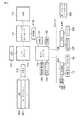
まず、図1および図2を参照して、本発明の一実施形態に係る情報処理装置の構成について説明する。この情報処理装置は、例えば、ノートブック型パーソナルコンピュータ10として実現されている。 First, the configuration of an information processing apparatus according to an embodiment of the present invention will be described with reference to FIG. 1 and FIG. This information processing apparatus is realized as, for example, a notebook
図1はノートブック型パーソナルコンピュータ10のディスプレイユニットを開いた状態における正面図である。本コンピュータ10は、コンピュータ本体11と、ディスプレイユニット12とから構成されている。ディスプレイユニット12には、TFT−LCD(Thin Film Transistor Liquid Crystal Display)17から構成される表示装置が組み込まれており、そのLCD17の表示画面はディスプレイユニット12のほぼ中央に位置されている。 FIG. 1 is a front view of the notebook
ディスプレイユニット12は、コンピュータ本体11に対して開放位置と閉塞位置との間を回動自在に取り付けられている。コンピュータ本体11は薄い箱形の筐体を有しており、その上面にはキーボード13、本コンピュータ10を電源オン/オフするための電源ボタン14、入力操作パネル15、タッチパッド16などが配置されている。 The
入力操作パネル15は、押されたボタンに対応するイベントを入力する入力装置であり、複数の機能をそれぞれ起動するための複数のボタンを備えている。これらボタン群には、TV起動ボタン15A、DVD/CD起動ボタン15Bも含まれている。TV起動ボタン15Aは、TV放送番組データの再生、視聴及び記録を行うためのTV機能を起動するためのボタンである。DVD/CD起動ボタン15Bは、DVDまたはCDに記録されたビデオコンテンツを再生するためのボタンである。 The
次に、図2を参照して、本コンピュータ10のシステム構成について説明する。 Next, the system configuration of the
本コンピュータ10は、図2に示されているように、CPU111、ノースブリッジ112、主メモリ113、グラフィクスコントローラ114、サウスブリッジ119、BIOS−ROM120、ハードディスクドライブ(HDD)121、光ディスクドライブ(ODD)122、TVチューナ123、エンベデッドコントローラ/キーボードコントローラIC(EC/KBC)124、ネットワークコントローラ125、バッテリ126、ACアダプタ127、電源コントローラ(PSC)128等を備えている。 As shown in FIG. 2, the
CPU111は本コンピュータ10の動作を制御するために設けられたプロセッサであり、ハードディスクドライブ(HDD)121から主メモリ113にロードされるOS(Operating System)200やこのOSに管理されるユーティリティ(又はアプリケーション)201などのソフトウェアを実行する。 The
また、CPU111は、BIOS−ROM120に格納されたシステムBIOS(Basic Input Output System)も実行する。システムBIOSはハードウェア制御のためのプログラムである。 The
ノースブリッジ112はCPU111のローカルバスとサウスブリッジ119との間を接続するブリッジデバイスである。ノースブリッジ112には、主メモリ113をアクセス制御するメモリコントローラも内蔵されている。また、ノースブリッジ112は、AGP(Accelerated Graphics Port)バスなどを介してグラフィクスコントローラ114との通信を実行する機能も有している。 The
グラフィクスコントローラ114は本コンピュータ10のディスプレイモニタとして使用されるLCD17を制御する表示コントローラである。このグラフィクスコントローラ114はビデオメモリ(VRAM)114Aに書き込まれた映像データをLCD17に表示する。 The
サウスブリッジ119は、LPC(Low Pin Count)バス上の各デバイス、およびPCI(Peripheral Component Interconnect)バス上の各デバイスを制御する。また、サウスブリッジ119は、HDD121、ODD122を制御するためのIDE(Integrated Drive Electronics)コントローラを内蔵している。さらに、サウスブリッジ119は、TVチューナ123を制御する機能、およびBIOS−ROM120をアクセス制御するための機能も有している。 The
HDD121は、各種ソフトウェア及びデータを格納する記憶装置である。光ディスクドライブ(ODD)123は、ビデオコンテンツが格納されたDVD、CDなどの記憶メディアを駆動するためのドライブユニットである。TVチューナ123は、TV放送番組のような放送番組データを外部から受信するための受信装置である。 The HDD 121 is a storage device that stores various software and data. An optical disk drive (ODD) 123 is a drive unit for driving a storage medium such as a DVD or a CD in which video content is stored. The TV tuner 123 is a receiving device for receiving broadcast program data such as a TV broadcast program from the outside.
ネットワークコントローラ125は、例えばインターネットなどの外部ネットワークとの通信を実行する通信装置である。 The
エンベデッドコントローラ/キーボードコントローラIC(EC/KBC)124は、電力管理を行うためのエンベデッドコントローラと、キーボード(KB)13およびタッチパッド16を制御するためのキーボードコントローラとが集積された1チップマイクロコンピュータである。 The embedded controller / keyboard controller IC (EC / KBC) 124 is a one-chip microcomputer in which an embedded controller for power management and a keyboard controller for controlling the keyboard (KB) 13 and the
電源コントローラ(PSC)128は、エンベデッドコントローラ(EC)からの指示に応じ、バッテリ126の電源、またはACアダプタ127を介して外部から供給される外部電源に基づいて本コンピュータ10の各コンポーネントに必要な電源を生成して供給する装置である。 The power controller (PSC) 128 is necessary for each component of the
図3は、バッテリ126に備えられるEEPROMに格納されている情報の一部を示す図である。 FIG. 3 is a diagram showing a part of information stored in the EEPROM provided in the
バッテリ126には、当該バッテリに関する各種の情報が格納されたEEPROM126Aが備えられている。このEEPROM126Aには、バッテリ126のローバッテリ状態を判断する基準値として3種類のローバッテリレベルLB0,LB1,LB2を示すパラメータ(数値)が記憶されている。これらの値は、PSC128等により使用される。 The
レベルLB0は、コンピュータ10の動作モードがスタンバイモードに移行する場合のトリガーとして使用される。例えばバッテリ126がローバッテリ状態となったときにスタンバイモードへ移行させるアクションが予め設定されている場合、バッテリ126の電子電圧がレベルLB0以下になったときにスタンバイモードへの移行が実行されることとなる。 The level LB0 is used as a trigger when the operation mode of the
レベルLB1は、レベルLB0よりも低いレベルであり、コンピュータ10の動作モードが休止モードに移行する場合のトリガーとして使用される。例えばバッテリ126がローバッテリ状態となったときに休止モードへ移行させるアクションが予め設定されている場合、バッテリ126の電子電圧がレベルLB0以下になったときに休止モードへの移行が実行されることとなる。 The level LB1 is a level lower than the level LB0, and is used as a trigger when the operation mode of the
レベルLB2は、レベルLB1よりも低いレベルであり、コンピュータ10の動作モードが停止モードに移行する場合のトリガーとして使用される。バッテリ126の電子電圧がレベルLB2以下になったときには、バッテリの残量は殆ど無く、スタンバイモードや休止モードの維持もできない状態となるため、停止モードへの移行が実行されることとなる。 The level LB2 is a level lower than the level LB1, and is used as a trigger when the operation mode of the
図4は、バッテリ126の電圧と放電率との関係を示す図である。 FIG. 4 is a diagram illustrating the relationship between the voltage of the
図4に示されるように、バッテリ126の放電率(%)が増加すると、その残存容量が低下し、これによりバッテリ126の電圧(V)が低下する。前述のローバッテリレベルLB0,LB1,LB2は、放電率がそれぞれx(%)、x+3(%)、x+5(%)のときのバッテリ電圧に相当する。バッテリ126の電圧(V)が低下するに従い、各ローバッテリレベルがLB0,LB1,LB2の順でPSC128により検出されるようになっている。 As shown in FIG. 4, when the discharge rate (%) of the
図5は、ローバッテリレベル検出の処理に関わる要素の構成の一例を示すブロック図である。
ローバッテリレベル検出の処理には、バッテリ126、PSC128、EC124A、BIOS120A、OS200などの要素が関係する。FIG. 5 is a block diagram showing an example of the configuration of elements involved in the low battery level detection process.
The low battery level detection process involves elements such as the
OS200は、例えば前述のユーティリティ(又はアプリケーション)201において事前に設定されたバッテリ切れアラームアクションの設定内容(例えば「バッテリがローバッテリ状態となったときに動作モードを休止モードへ移行させる」という設定内容)をBIOS120Aに通知するとともに、BIOS120Aから通知されるバッテリ126の残存容量(mAh)に基づいてバッテリ切れの有無を識別し、アラームアクションを実行するか否かを決定する。また、OS200は、バッテリ切れアラームアクションを実行する場合には、設定内容に示される動作モード(例えば「休止モード」)への移行をEC124Aに対して指示する。また、OS200は、BIOS120Aから通知されるバッテリ126の残存容量(mAh)をパーセンテージに換算してLCD17の画面上に表示するすることができる。 The
バッテリ126は、前述したように、ローバッテリレベルLB0,LB1,LB2を示すパラメータが記憶されたEEPROM126Aを備えている。 As described above, the
PSC128は、バッテリ126の端子を通じてバッテリ126の電圧を監視することができる。また、PSC128は、バッテリ126のEEPROM126Aに記憶されるパラメータによりローバッテリレベルLB0,LB1,LB2を知得し、バッテリ126の電圧がレベルLB0,LB1,LB2の各々に達したことを検出する度に、該当する残存容量(mAh)を示す値をEC124Aへ送ることができる。勿論、ローバッテリレベルのときだけでなく、刻一刻、検出されるバッテリ電圧に相当する残存容量の値をEC124Aへ送ることもできる。そのほか、バッテリ126の満充電容量を示す値をEC124Aへ送ることもできる。 The
EC124Aは、図6に示されるようにレジスタ124Bを備えている。このレジスタ124Bは、バッテリ126の満充電容量を示す値や、バッテリ126の残存容量を示す値などを記憶することができる。また、EC124Aは、PSC128からバッテリ126の残存容量の値が新たに送られてくると、その値をレジスタ124B内の所定の領域に書き込み、BIOS120Aに対して残存容量の更新が発生したことを通知することができる。 The
BIOS120Aは、EC124Aからの更新通知に応じてEC124A内のレジスタ124Bから情報を読み出す。BIOS120Aは、スタンバイモードへ移行させるアクションが設定されていれば、レジスタ124Bから読み出した情報に示される残存容量からマージンとして所定値(ここでは、満充電容量の2%分の容量C2%)を減算した値を残存容量としてOS200に通知する。例えば、レジスタ124Bから読み出した情報に示される残存容量がレベルLB0に相当する残存容量C0である場合、BIOS120Aは、この残存容量C0から容量C2%を減算した値を残存容量としてOS200に通知する。この場合、OS200はバッテリ切れを認識し、スタンバイモードへ移行させるアクションを実行することとなる。 The
また、BIOS120Aは、休止モードへ移行させるアクションが設定されていれば、上述のような減算は行わず、レジスタ124Bから読み出した情報に示される残存容量にに所定値(ここでは、満充電容量の1%分の容量C1%)を加算した値を残存容量としてOS200に通知する。例えば、レジスタ124Bから読み出した情報に示される残存容量がレベルLB1に相当する残存容量C1である場合、BIOS120Aは、この残存容量C1に容量C1%を加算した値を残存容量としてOS200に通知する。なお、残存容量C1に1%分の容量C1%を加算した値は、上記残存容量C0から2%分の容量C2%を減算した値に一致するものとする。この場合、OS200はバッテリ切れを認識し、休止モードへ移行させるアクションを実行することとなる。 In addition, if the action for shifting to the sleep mode is set, the
なお、上述の演算は、BIOS120Aで行う代わりに、別のソフトウェアやハードウェアで行うように構成してもよい。 In addition, you may comprise so that the above-mentioned calculation may be performed with another software or hardware instead of performing with BIOS120A.
図7は、OS200に管理されるユーティリティ201の機能構成の一例を示す図である。 FIG. 7 is a diagram illustrating an example of a functional configuration of the
ユーティリティ201は、設定部301、設定内容通知部302、バッテリ切れ認識部303、アクション実行部304などの各種機能を備えている。 The
設定部301は、バッテリ切れアラームアクションに関する設定画面を通じてユーザが指定する情報の設定を行うものである。 The setting unit 301 sets information specified by the user through a setting screen related to a battery low alarm action.
設定内容通知部302は、設定部301において設定された内容(例えば「バッテリがローバッテリ状態となったときに動作モードを休止モードへ移行させる」という設定内容)をBIOS120Aに通知するものである。 The setting
バッテリ切れ認識部303は、BIOS120Aから通知されるバッテリ126の残存容量が基準値以下である場合にバッテリ切れを認識するものである。 The battery
アクション実行部304は、バッテリ切れ認識部303においてバッテリ切れが認識された場合に、設定内容に示される動作モード(例えば「休止モード」)への移行をEC124Aに対して指示するものである。 The
図8は、BIOS120Aの機能構成の一例を示す図である。 FIG. 8 is a diagram illustrating an example of a functional configuration of the
BIOS120Aは、アラーム設定内容受付部401、バッテリ残量取得部402、OS通知用残量算出部403、残量通知部404などの各種機能を備えている。 The
アラーム設定内容受付部401は、OS200から通知されるバッテリ切れアラームアクションに関する設定内容を受け付けて保持するものである。 The alarm setting
バッテリ残量取得部402は、EC124Aからの更新通知に応じてEC124A内のレジスタ124Bから残存容量を含む情報を読み出すものである。 The battery remaining
OS通知用残量算出部403は、スタンバイモードへ移行させるアクションが設定されている場合にはバッテリ残量取得部402により読み出された情報に示される残存容量から所定値を減算してOS通知用の残存容量を算出する一方、休止モードへ移行させるアクションが設定されている場合にはバッテリ残量取得部402により読み出された情報に示される残存容量に所定値を加算してOS通知用の残存容量を算出するものである。 The OS notification remaining
残量通知部404は、OS通知用残量算出部403により算出された残存容量をOS200に通知するものである。 The remaining
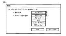
図9は、ユーティリティ201により実現される設定画面の一例を示す図である。 FIG. 9 is a diagram illustrating an example of a setting screen realized by the
図9の設定画面は、バッテリ切れアラームアクションに関する設定画面であり、ユーティリティ201に備えられる設定部301により実現される。この設定画面においては、例えば図9のようにチェックボックスにチェックマークを入れることにより、バッテリ切れアラームアクションを有効にすることができる。この場合、アラームの通知方法や、アラーム後の動作などについて所望の指定を行える。 The setting screen of FIG. 9 is a setting screen related to the battery exhaustion alarm action, and is realized by the setting unit 301 provided in the
アラームの通知方法としては、「メッセージ」や「音声」などが用意されている。アラーム後の動作としては、省電力モードである「スタンバイ」や「休止」が用意されている。そのほか、「シャットダウン」や「何もしない」なども用意されている。これらについて所望の指定を行ってOKボタンを押下すると、設定が完了する。 As the alarm notification method, “message”, “voice” and the like are prepared. As an operation after the alarm, “standby” and “pause” which are power saving modes are prepared. In addition, "Shutdown" and "Do nothing" are also available. When desired designation is made for these items and the OK button is pressed, the setting is completed.
次に、図10のフローチャートを参照して、PSC128及びEC124Aの動作を説明する。 Next, operations of the
PSC128は、バッテリ126の端子を通じてバッテリ126の電圧を検出し、その電圧がレベルLB0,LB1,LB2の値に達するかどうかを監視する(ステップA1)。そして、バッテリ126の電圧がレベルLB0,LB1,LB2のいずれかに達したならば(ステップA2のYES)、PSC128は、該当する残存容量を示す値をEC124Aへ送る(ステップA3)。これにより、EC124Aは、PSC128から送られる残存容量を示す値をレジスタ124B内の所定の領域に書き込み、BIOS120Aに対して残存容量の更新が発生したことを通知する(ステップA4)。その後、ステップA1からの処理が繰り返される。 The
次に、図11のフローチャートを参照して、BIOS120A及びOS200の動作を説明する。 Next, operations of the
OS200に管理されるユーティリティ201は、バッテリ切れアラームアクションの設定画面を通じてユーザが指定する内容の設定を行うと(ステップB1)、その設定内容をBIOS120Aへ通知する(ステップB2)。 When the
BIOS120Aは、この通知を受けた後、EC124Aからの更新通知があるまで待機する(ステップB3)。 After receiving this notification, the
EC124Aからの更新通知があると(ステップB4のYES)、BIOS120Aは、EC124A内のレジスタ124Bからバッテリ126の残存容量を読み出す(ステップB5)。次いで、BIOS120Aは、OS200側から通知された設定内容に示されるアラーム後の動作が何であるかを確認する(ステップB6、B7)。 When there is an update notification from the
アラーム後の動作が「スタンバイ」である場合(ステップB6のYES)、BIOS120Aは、レジスタ124Bから読み出した残存容量から、満充電容量の2%分の容量を減算する(ステップB8)。 When the operation after the alarm is “standby” (YES in step B6), the
一方、アラーム後の動作が「休止」である場合(ステップB6のNO、ステップB7のYES)、BIOS120Aは、レジスタ124Bから読み出した残存容量に、満充電容量の1%分の容量を加算する(ステップB9)。 On the other hand, when the operation after the alarm is “pause” (NO in step B6, YES in step B7), the
また、アラーム後の動作が「シャットダウン」等である場合(ステップB7のNO)、BIOS120Aは、レジスタ124Bから読み出した残存容量から、満充電容量の2%分の容量を減算する(ステップB8)。 When the operation after the alarm is “Shutdown” or the like (NO in Step B7), the
そして、BIOS120Aは演算後の残存容量をOS200に通知する(ステップB10)。 Then, the
残存容量の通知を受けたOS200は、その残存容量が基準値以下であることを検出すると、バッテリ切れの状態であることを認識し(ステップB11)、設定されているバッテリ切れアラームアクションを実行する(ステップB12)。 When the
このように本実施形態によれば、バッテリ切れアラームアクションの設定において休止モードへ移行させるアクションが設定されている場合、BIOS120AはEC124Aから得られる残存容量に所定値を加算した値をOS200へ伝えるため、従来よりも低いバッテリレベルにおいて休止モードへの移行が実行されるととなり、ユーザは長時間にわたってコンピュータを使った作業を続けることができる。 As described above, according to the present embodiment, when the action for shifting to the hibernation mode is set in the setting of the battery exhaustion alarm action, the
なお、本発明は上記実施形態そのままに限定されるものではなく、実施段階ではその要旨を逸脱しない範囲で構成要素を変形して具体化できる。また、上記実施形態に開示されている複数の構成要素の適宜な組み合わせにより、種々の発明を形成できる。例えば、実施形態に示される全構成要素から幾つかの構成要素を削除してもよい。さらに、異なる実施形態にわたる構成要素を適宜組み合わせてもよい。 Note that the present invention is not limited to the above-described embodiment as it is, and can be embodied by modifying the components without departing from the scope of the invention in the implementation stage. In addition, various inventions can be formed by appropriately combining a plurality of components disclosed in the embodiment. For example, some components may be deleted from all the components shown in the embodiment. Furthermore, constituent elements over different embodiments may be appropriately combined.
10…コンピュータ、120A…BIOS、200…OS,201…ユーティリティ、124…EC/KBC、124A…EC、124B…EC内部レジスタ、126…バッテリ、126A…バッテリEEPROM、127…ACアダプタ、128…PSC。 DESCRIPTION OF
Claims (11)
Translated fromJapanese前記情報処理装置の動作モードを第1の消費電力量で動作する第1の消費電力モードまたは前記第1の消費電力量よりも小さい第2の消費電力量で動作する第2の消費電力モードへ移行させるアクションの設定をする設定手段と、
前記第1の消費電力モードへ移行させるアクションが設定されている状態で前記バッテリの残容量が第1の容量に達する場合、前記第1の消費電力モードに移行させ、前記第2の消費電力モードへ移行させるアクションが設定されている状態で前記バッテリの残容量が前記第1の容量よりも小さい第2の容量に達する場合、前記第2の消費電力モードに移行させる制御手段と、
を具備することを特徴とする情報処理装置。In an information processing apparatus having a battery,
The operation mode of the information processing apparatus is changed to a first power consumption mode that operates at a first power consumption amount or a second power consumption mode that operates at a second power consumption amount smaller than the first power consumption amount. A setting means for setting an action to be transferred;
When the remaining capacity of the battery reaches the first capacity in the state in which the action for shifting to the first power consumption mode is set, the second power consumption mode is switched to the first power consumption mode. Control means for shifting to the second power consumption mode when the remaining capacity of the battery reaches a second capacity smaller than the first capacity with the action to shift to
An information processing apparatus comprising:
前記情報処理装置の動作モードを第1の消費電力量で動作する第1の消費電力モードまたは前記第1の消費電力量よりも小さい第2の消費電力量で動作する第2の消費電力モードへ移行させる動作の設定をする設定手段と、
前記第1の消費電力モードまたは前記第2の消費電力モードへ移行させるモード移行手段と、
前記第1の消費電力モードへ移行させるアクションが設定されている状態で前記バッテリの前記バッテリの残容量が第1の容量に達する場合、前記モード移行手段に前記第1の容量から所定値が減算された値を通知し、前記第2の消費電力モードへ移行させるアクションが設定されている状態で前記バッテリの前記バッテリの残容量が前記第1の容量よりも小さい第2の容量に達する場合、前記モード移行手段に前記第2の容量に所定値が加算された値を通知する通知手段と、を具備することを特徴とし、
前記モード移行手段は、前記通知手段から通知された値に基づいて消費電力モード移行を実行することを特徴とする情報処理装置。In an information processing apparatus having a battery,
The operation mode of the information processing apparatus is changed to a first power consumption mode that operates at a first power consumption amount or a second power consumption mode that operates at a second power consumption amount smaller than the first power consumption amount. Setting means for setting the operation to be transferred;
Mode shifting means for shifting to the first power consumption mode or the second power consumption mode;
When the remaining capacity of the battery reaches the first capacity with the action for shifting to the first power consumption mode set, a predetermined value is subtracted from the first capacity to the mode shifting means. The remaining capacity of the battery of the battery reaches a second capacity that is smaller than the first capacity in a state in which an action for transferring to the second power consumption mode is set. A notification means for notifying the mode transition means of a value obtained by adding a predetermined value to the second capacity;
The information processing apparatus according to claim 1, wherein the mode transition unit performs a power consumption mode transition based on a value notified from the notification unit.
前記情報処理装置の動作モードを第1の消費電力量で動作する第1の消費電力モードまたは前記第1の消費電力量よりも小さい第2の消費電力量で動作する第2の消費電力モードへ移行させるアクションを設定し、
前記第1の消費電力モードへ移行させるアクションが設定されている状態で前記バッテリの残容量が第1の容量に達する場合、前記第1の消費電力モードに移行させ、前記第2の消費電力モードへ移行させるアクションが設定されている状態で前記バッテリの残容量が前記第1の容量よりも小さい第2の容量に達する場合、前記第2の消費電力モードに移行させることを特徴とする消費電力制御方法。In a power consumption control method executed by an information processing apparatus having a battery,
The operation mode of the information processing apparatus is changed to a first power consumption mode that operates at a first power consumption amount or a second power consumption mode that operates at a second power consumption amount smaller than the first power consumption amount. Set the action to be migrated,
When the remaining capacity of the battery reaches the first capacity in the state in which the action for shifting to the first power consumption mode is set, the second power consumption mode is switched to the first power consumption mode. When the action to shift to is set, and the remaining capacity of the battery reaches a second capacity that is smaller than the first capacity, the power consumption is shifted to the second power consumption mode. Control method.
Priority Applications (2)
| Application Number | Priority Date | Filing Date | Title |
|---|---|---|---|
| JP2006051524AJP2007233503A (en) | 2006-02-28 | 2006-02-28 | Information processing apparatus and power consumption control method |
| US11/710,814US20070204181A1 (en) | 2006-02-28 | 2007-02-26 | Information processing apparatus and power consumption method |
Applications Claiming Priority (1)
| Application Number | Priority Date | Filing Date | Title |
|---|---|---|---|
| JP2006051524AJP2007233503A (en) | 2006-02-28 | 2006-02-28 | Information processing apparatus and power consumption control method |
Publications (1)
| Publication Number | Publication Date |
|---|---|
| JP2007233503Atrue JP2007233503A (en) | 2007-09-13 |
Family
ID=38445437
Family Applications (1)
| Application Number | Title | Priority Date | Filing Date |
|---|---|---|---|
| JP2006051524APendingJP2007233503A (en) | 2006-02-28 | 2006-02-28 | Information processing apparatus and power consumption control method |
Country Status (2)
| Country | Link |
|---|---|
| US (1) | US20070204181A1 (en) |
| JP (1) | JP2007233503A (en) |
Cited By (2)
| Publication number | Priority date | Publication date | Assignee | Title |
|---|---|---|---|---|
| JP2013054667A (en)* | 2011-09-06 | 2013-03-21 | Toshiba Tec Corp | Information processor and program |
| WO2025174028A1 (en)* | 2024-02-16 | 2025-08-21 | 삼성전자 주식회사 | Electronic device for controlling booting speed, operating method thereof, and storage medium |
Families Citing this family (6)
| Publication number | Priority date | Publication date | Assignee | Title |
|---|---|---|---|---|
| TWI321752B (en)* | 2005-10-06 | 2010-03-11 | Quanta Comp Inc | Audio/video playing system |
| JP2007330016A (en)* | 2006-06-07 | 2007-12-20 | Nec Corp | Power unit, information processing system, and method and program for controlling power unit |
| DE102008039795B3 (en)* | 2008-08-26 | 2010-01-07 | Fujitsu Siemens Computers Gmbh | Computer system and method for power-saving operation of a computer system |
| US20120320281A1 (en)* | 2011-06-14 | 2012-12-20 | Teruo Kinoshita | Television receiver apparatus and control method |
| US20140245042A1 (en)* | 2013-02-28 | 2014-08-28 | Barnesandnoble.Com Llc | Method for hibernation control based on battery capacity |
| US10964290B2 (en) | 2018-12-28 | 2021-03-30 | Disney Enterprises, Inc. | Selective reduction of pixel intensity to enhance energy efficiency during display of an image |
Family Cites Families (6)
| Publication number | Priority date | Publication date | Assignee | Title |
|---|---|---|---|---|
| US5283905A (en)* | 1991-06-24 | 1994-02-01 | Compaq Computer Corporation | Power supply for computer system manager |
| US5633573A (en)* | 1994-11-10 | 1997-05-27 | Duracell, Inc. | Battery pack having a processor controlled battery operating system |
| JPH09215213A (en)* | 1996-02-05 | 1997-08-15 | Fuji Elelctrochem Co Ltd | Over-discharge prevention device |
| US5822600A (en)* | 1996-07-19 | 1998-10-13 | Compaq Computer Corporation | Dynamic hibernation time in a computer system |
| JP2000214965A (en)* | 1999-01-25 | 2000-08-04 | Toshiba Corp | Computer system and battery event management method |
| US7296171B2 (en)* | 2004-11-10 | 2007-11-13 | Microsoft Corporation | Selecting a power state based on predefined parameters |
- 2006
- 2006-02-28JPJP2006051524Apatent/JP2007233503A/enactivePending
- 2007
- 2007-02-26USUS11/710,814patent/US20070204181A1/ennot_activeAbandoned
Cited By (2)
| Publication number | Priority date | Publication date | Assignee | Title |
|---|---|---|---|---|
| JP2013054667A (en)* | 2011-09-06 | 2013-03-21 | Toshiba Tec Corp | Information processor and program |
| WO2025174028A1 (en)* | 2024-02-16 | 2025-08-21 | 삼성전자 주식회사 | Electronic device for controlling booting speed, operating method thereof, and storage medium |
Also Published As
| Publication number | Publication date |
|---|---|
| US20070204181A1 (en) | 2007-08-30 |
Similar Documents
| Publication | Publication Date | Title |
|---|---|---|
| JP4175838B2 (en) | Information processing apparatus with standby mode, standby mode start method and standby mode cancel method | |
| JP2007233503A (en) | Information processing apparatus and power consumption control method | |
| US20100056272A1 (en) | Music player for video game consoles and electronic devices operable in sleep or power-saving modes | |
| JP2005316855A (en) | Information processing apparatus, activation method thereof, and activation program thereof | |
| JP2004531814A (en) | Method and apparatus for improving the reliability of write-back cache information | |
| JP2009289193A (en) | Information processing apparatus | |
| JP2006048131A (en) | Information processing apparatus and display brightness control method | |
| JP2009288430A (en) | Information processing apparatus | |
| CN100480957C (en) | Information processing apparatus and resume control method | |
| JP4607545B2 (en) | Information processing apparatus and power control method | |
| US20070124613A1 (en) | Information processing apparatus and system control method | |
| JP5112542B1 (en) | Information processing apparatus and control method of information processing apparatus | |
| JP2010009538A (en) | Information processor | |
| JP2009157838A (en) | Information processing apparatus and fan control method | |
| JP2007323362A (en) | Information processing apparatus and control method | |
| JP2013007974A (en) | Electronic apparatus, control method of electronic apparatus, and control program of electronic apparatus | |
| JP2011096132A (en) | Information processing apparatus and display control method | |
| JP2007128492A (en) | Information processing apparatus and activation control method | |
| JP2007206839A (en) | Electronic device and operation control method | |
| JP2004021603A (en) | Electronic device and suspend / resume method | |
| US20140050337A1 (en) | Personal computer to output audio in a non-operative state | |
| JP2006172325A (en) | Device state control method and information processing apparatus | |
| JP2010011682A (en) | Information processor, battery unit, battery charging method, and program | |
| JP2011113407A (en) | Information processor and control method of the same | |
| JP4751016B2 (en) | Electronic device and power supply control method |