JP2007232172A - Microvalve device - Google Patents
Microvalve deviceDownload PDFInfo
- Publication number
- JP2007232172A JP2007232172AJP2006057667AJP2006057667AJP2007232172AJP 2007232172 AJP2007232172 AJP 2007232172AJP 2006057667 AJP2006057667 AJP 2006057667AJP 2006057667 AJP2006057667 AJP 2006057667AJP 2007232172 AJP2007232172 AJP 2007232172A
- Authority
- JP
- Japan
- Prior art keywords
- liquid
- flow path
- channel
- valve
- microvalve device
- Prior art date
- Legal status (The legal status is an assumption and is not a legal conclusion. Google has not performed a legal analysis and makes no representation as to the accuracy of the status listed.)
- Withdrawn
Links
- 239000007788liquidSubstances0.000claimsabstractdescription226
- 239000012530fluidSubstances0.000claimsabstractdescription52
- 230000007246mechanismEffects0.000claimsabstractdescription17
- 238000011144upstream manufacturingMethods0.000claimsdescription17
- 239000000463materialSubstances0.000abstractdescription9
- 238000010276constructionMethods0.000abstract1
- XLYOFNOQVPJJNP-UHFFFAOYSA-NwaterSubstancesOXLYOFNOQVPJJNP-UHFFFAOYSA-N0.000description27
- 238000000034methodMethods0.000description18
- 230000004048modificationEffects0.000description10
- 238000012986modificationMethods0.000description10
- 238000006243chemical reactionMethods0.000description7
- 239000011521glassSubstances0.000description7
- VYPSYNLAJGMNEJ-UHFFFAOYSA-Nsilicon dioxideInorganic materialsO=[Si]=OVYPSYNLAJGMNEJ-UHFFFAOYSA-N0.000description7
- 238000005530etchingMethods0.000description5
- 230000008569processEffects0.000description5
- 239000000758substrateSubstances0.000description5
- KRHYYFGTRYWZRS-UHFFFAOYSA-NFluoraneChemical compoundFKRHYYFGTRYWZRS-UHFFFAOYSA-N0.000description4
- 230000000903blocking effectEffects0.000description4
- YTJSFYQNRXLOIC-UHFFFAOYSA-NoctadecylsilaneChemical compoundCCCCCCCCCCCCCCCCCC[SiH3]YTJSFYQNRXLOIC-UHFFFAOYSA-N0.000description4
- 238000000926separation methodMethods0.000description4
- 238000004519manufacturing processMethods0.000description3
- 238000003672processing methodMethods0.000description3
- LFQSCWFLJHTTHZ-UHFFFAOYSA-NEthanolChemical compoundCCOLFQSCWFLJHTTHZ-UHFFFAOYSA-N0.000description2
- GWEVSGVZZGPLCZ-UHFFFAOYSA-NTitan oxideChemical compoundO=[Ti]=OGWEVSGVZZGPLCZ-UHFFFAOYSA-N0.000description2
- 238000010586diagramMethods0.000description2
- 239000004205dimethyl polysiloxaneSubstances0.000description2
- 238000005553drillingMethods0.000description2
- 230000000694effectsEffects0.000description2
- 238000000605extractionMethods0.000description2
- 230000010354integrationEffects0.000description2
- 239000010410layerSubstances0.000description2
- 229920000435poly(dimethylsiloxane)Polymers0.000description2
- 238000012545processingMethods0.000description2
- 239000005871repellentSubstances0.000description2
- 239000000126substanceSubstances0.000description2
- OGIDPMRJRNCKJF-UHFFFAOYSA-Ntitanium oxideInorganic materials[Ti]=OOGIDPMRJRNCKJF-UHFFFAOYSA-N0.000description2
- 239000005407aluminoborosilicate glassSubstances0.000description1
- 239000005354aluminosilicate glassSubstances0.000description1
- 238000004458analytical methodMethods0.000description1
- 238000013459approachMethods0.000description1
- 238000009412basement excavationMethods0.000description1
- 230000008859changeEffects0.000description1
- 238000005520cutting processMethods0.000description1
- 238000001514detection methodMethods0.000description1
- 238000011161developmentMethods0.000description1
- 238000006193diazotization reactionMethods0.000description1
- 238000005516engineering processMethods0.000description1
- 238000002156mixingMethods0.000description1
- 239000000203mixtureSubstances0.000description1
- 238000006396nitration reactionMethods0.000description1
- -1polydimethylsiloxanePolymers0.000description1
- 239000010453quartzSubstances0.000description1
- 230000002940repellentEffects0.000description1
- 238000009420retrofittingMethods0.000description1
- 238000005488sandblastingMethods0.000description1
- 239000005361soda-lime glassSubstances0.000description1
- 238000000638solvent extractionMethods0.000description1
- 238000004611spectroscopical analysisMethods0.000description1
- 238000004381surface treatmentMethods0.000description1
- 239000002335surface treatment layerSubstances0.000description1
- 238000001039wet etchingMethods0.000description1
Images


Landscapes
- Micromachines (AREA)
- Sliding Valves (AREA)
- Fluid-Driven Valves (AREA)
Abstract
Description
Translated fromJapanese本発明は、マイクロバルブ装置に関し、特に、微細な流路を流れる液体の遮断及び開放を行うマイクロバルブ装置に関する。 The present invention relates to a microvalve device, and more particularly, to a microvalve device that blocks and opens a liquid flowing through a fine flow path.
従来から、化学反応の高速化や微少量での反応、オンサイト分析等の観点から、化学反
応を微小空間で行うための集積化技術が注目されており、そのため研究が精力的に進めら
れている。Conventionally, integration technology for performing chemical reactions in a minute space has attracted attention from the viewpoint of speeding up chemical reactions, reactions in minute amounts, on-site analysis, etc. Yes.
このような集積化技術の1つとして、図22に示すようにマイクロ化学チップを用いて、液体試料の混合、反応、分離、抽出、検出等を行うマイクロ化学システムがある。このマイクロ化学システムで行われる反応の例としては、ジアゾ化反応、ニトロ化反応、抗原抗体反応等がある。また、抽出や分離の例としては、溶媒抽出、電気泳動分離、カラム分離等がある。そして、このマイクロ化学システムで反応等を行う際に、流路内の液体を遮断及び開放することができるマイクロバルブ装置が用いられている。 As one of such integration techniques, there is a microchemical system that performs mixing, reaction, separation, extraction, detection, and the like of a liquid sample using a microchemical chip as shown in FIG. Examples of reactions performed in this microchemical system include diazotization reaction, nitration reaction, antigen-antibody reaction and the like. Examples of extraction and separation include solvent extraction, electrophoretic separation, and column separation. And when performing a reaction etc. with this microchemical system, the microvalve apparatus which can interrupt | block and open | release the liquid in a flow path is used.
例えば、溝及び弁構造体に撥水表面処理が施され、アクチュエータが溝に沿って流路を遮断する方向に弁構造体を駆動する構造のマイクロバルブがある(例えば、特許文献1参照)。 For example, there is a microvalve having a structure in which a water repellent surface treatment is applied to a groove and a valve structure, and an actuator drives the valve structure in a direction of blocking a flow path along the groove (see, for example, Patent Document 1).
また、温度操作によるキャビティ内の圧力変化によって、可動部を変形させ、この可動部がゲート部と密着することにより、微小流路が閉じられる構造となっているマイクロバルブがある(例えば、特許文献2参照)。 In addition, there is a microvalve that has a structure in which a micro flow path is closed by deforming a movable part due to a pressure change in the cavity caused by temperature operation, and the movable part is in close contact with the gate part (for example, Patent Documents). 2).
また、光照射のオン・オフのみで微小流体の流れ方向を制御可能な光制御型微小スイッチングバルブがある。このバルブは、ポリジメチルシロキサン(PDMS)を材質とするT型のマイクロチャネルを作製し、酸化チタンをコートした石英基板と接合することにより作製される。このT型のマイクロチャネルのうち、溶液を通す流路のみ、波長325nmのHe−Cdレーザーを酸化チタン表面へ照射し超親水化することにより、溶液は、その超親水化した流路にのみ流入する。このように光照射を用いてチャネル内壁の濡れ性を制御することにより、スイッチングバルブとして機能する(例えば、非特許文献1参照)。 There is also a light control type micro switching valve that can control the flow direction of micro fluid only by turning on / off light irradiation. This valve is manufactured by manufacturing a T-type microchannel made of polydimethylsiloxane (PDMS) and bonding it to a quartz substrate coated with titanium oxide. Of these T-shaped microchannels, only the flow path through which the solution passes is irradiated with a He—Cd laser having a wavelength of 325 nm onto the titanium oxide surface to make it superhydrophilic, so that the solution flows only into the superhydrophilic flow path. To do. By controlling the wettability of the channel inner wall using light irradiation in this way, it functions as a switching valve (for example, see Non-Patent Document 1).
さらに、多段階のウェットエッチングによりチャネル深さを制御したマイクロチャネルがある。このマイクロチャネルは、チャネル表面部分をオクタデシルシラン(ODS)修飾により疎水化することで所定の位置で液体を止めようというものである(例えば、非特許文献2参照)。
しかしながら、アクチュエータが弁構造体を駆動する構造の上記特許文献1のマイクロバルブでは、機械的に駆動される弁構造体をチップ内に集積しているため、複雑な微細加工が必要である。また、機械的に駆動される弁構造体の加工精度が悪いと、流路と接触し、接触部分の撥水表面処理層が剥がれて、マイクロバルブの開閉の際における機密性を保つことができず、マイクロバルブとして機能しないという問題がある。 However, in the microvalve described in Patent Document 1 in which the actuator drives the valve structure, the mechanically driven valve structure is integrated in the chip, and thus complicated fine processing is required. In addition, if the mechanically driven valve structure is not processed accurately, it will come into contact with the flow path, and the water-repellent surface treatment layer at the contact portion will be peeled off, so that confidentiality can be maintained when opening and closing the microvalve. Therefore, there is a problem that it does not function as a micro valve.
また、上記特許文献2のマイクロバルブでは、微小流路が形成された基板とキャビティが形成された基板との間に、ダイヤフラムを配置するための複雑な微細加工が必要であり、さらに、可動部とゲート部との密着性が悪いと、マイクロバルブとして機能しないという問題がある。 Further, the microvalve disclosed in
また、上記非特許文献1のスイッチングバルブは、2つの流路のうちの一方の流路(超親水化した流路)のみに、溶液を誘導するだけであるため、溶液の流れを遮断及び開放することができないという問題がある。 Further, since the switching valve of Non-Patent Document 1 only guides the solution to one of the two channels (superhydrophilic channel), the flow of the solution is blocked and opened. There is a problem that you can not.
さらに、上記非特許文献2のマイクロチャネルは、チャネル表面部分をオクタデシルシラン(ODS)修飾により疎水化する必要があるため、コスト高となってしまうという問題がある。 Furthermore, the microchannel of Non-Patent
本発明の目的は、簡単な構造で、微細な流路を流れる液体の遮断及び開放を行うことができるマイクロバルブ装置を提供することにある。 An object of the present invention is to provide a microvalve device having a simple structure and capable of blocking and opening a liquid flowing through a fine channel.
上記目的を達成するために、請求項1記載のマイクロバルブ装置は、制御用流体を供給する流体制御機構と、前記供給された制御用流体が流れるバルブ流路構造とを備え、前記バルブ流路構造を流れる制御用流体を前記バルブ流路構造に接続された液体流路に供給することによって、前記液体流路を流れる液体を遮断及び開放するマイクロバルブ装置であって、前記バルブ流路構造は合流部で前記液体流路と交差するバルブ流路から成り、前記液体流路における前記合流部の上流側及び下流側の少なくとも一方に前記液体流路の断面積を小さくする堰が設置されたことを特徴とする。 In order to achieve the above object, the microvalve device according to claim 1 includes a fluid control mechanism for supplying a control fluid, and a valve channel structure through which the supplied control fluid flows. A microvalve device for blocking and opening a liquid flowing through the liquid flow path by supplying a control fluid flowing through the structure to a liquid flow path connected to the valve flow path structure, wherein the valve flow path structure is A dam that reduces the cross-sectional area of the liquid channel is provided on at least one of the upstream side and the downstream side of the merging unit in the liquid channel. It is characterized by.
請求項2記載のマイクロバルブ装置は、請求項1記載のマイクロバルブ装置において、前記液体流路の内壁は、接触角が前記液体流路を流れる液体に対して30度以下であることを特徴とする。 The microvalve device according to
請求項3記載のマイクロバルブ装置は、請求項1又は2記載のマイクロバルブ装置において、前記堰と前記バルブ流路との距離が100μm以下であることを特徴とする。 A microvalve device according to a third aspect is the microvalve device according to the first or second aspect, wherein the distance between the weir and the valve flow path is 100 μm or less.
請求項4記載のマイクロバルブ装置は、請求項1乃至3のいずれか1項に記載のマイクロバルブ装置において、前記合流部により規定された液体流路の空隙の高さをR1、前記堰により規定された液体流路の空隙の高さをR2、前記液体流路の前記液体に対する接触角をθ、前記液体の表面張力をσ、前記液体流路の上流側からの圧力をP1、前記液体流路の下流側からの圧力をP2、圧力P1と圧力P2との差P1−P2をΔPとするとき、前記堰により規定された液体流路の空隙の高さR2が下記式を満たすことを特徴とする、
R2<4・σ・cosθ・R1/(ΔP・R1+4・σ・cosθ)。The microvalve device according to claim 4 is the microvalve device according to any one of claims 1 to 3, wherein the height of the gap of the liquid flow path defined by the merging portion is defined by R1 and the weir. The height of the gap of the liquid channel formed is R2, the contact angle of the liquid channel with respect to the liquid is θ, the surface tension of the liquid is σ, the pressure from the upstream side of the liquid channel is P1, the liquid flow When the pressure from the downstream side of the passage is P2, and the difference P1-P2 between the pressure P1 and the pressure P2 is ΔP, the height R2 of the gap of the liquid flow passage defined by the weir satisfies the following formula: And
R2 <4 · σ · cos θ · R1 / (ΔP · R1 + 4 · σ · cos θ).
請求項5記載のマイクロ化学チップは、請求項1乃至4のいずれか1項に記載のマイクロバルブ装置を備えたことを特徴とする。 A microchemical chip according to a fifth aspect includes the microvalve device according to any one of the first to fourth aspects.
請求項6記載のマイクロ化学システムは、請求項1乃至4のいずれか1項に記載のマイクロバルブ装置を備えたことを特徴とする。 A microchemical system according to a sixth aspect includes the microvalve device according to any one of the first to fourth aspects.
請求項1記載のマイクロバルブ装置によれば、液体流路における合流部の上流側及び下流側の少なくとも一方に液体流路の断面積を小さくする堰が設置されたので、簡単な構造で、微細な流路を流れる液体の遮断及び開放を行うことができる。 According to the microvalve device of the first aspect, since the weir for reducing the cross-sectional area of the liquid flow path is installed on at least one of the upstream side and the downstream side of the confluence portion in the liquid flow path, It is possible to shut off and open the liquid flowing through a simple flow path.
請求項2記載のマイクロバルブ装置によれば、液体流路の内壁は、接触角が液体流路を流れる液体に対して30度以下であるので、液体流路2の内壁表面の液体に対する親和性を高くして制御流体の流れを抑制することができる。 According to the microvalve device of the second aspect, since the contact angle of the inner wall of the liquid channel is 30 degrees or less with respect to the liquid flowing through the liquid channel, the affinity of the inner wall surface of the
請求項3記載のマイクロバルブ装置によれば、堰とバルブ流路との距離が100μm以下であるので、制御流体をバルブ流路側に十分に押し戻すことができる。 According to the microvalve device of the third aspect, since the distance between the weir and the valve channel is 100 μm or less, the control fluid can be sufficiently pushed back to the valve channel side.
請求項4記載のマイクロバルブ装置によれば、堰により規定された液体流路の空隙の高さは、堰により規定された液体流路の空隙の高さR2がR2<4・σ・cosθ・R1/(ΔP・R1+4・σ・cosθ)を満たすので、堰により規定された液体流路においてより大きなラプラス圧を発生させることができ、もって液体流路の上流側からかかる圧力に抗して下流側への制御流体の流れを抑制することができる。 According to the microvalve device of claim 4, the height of the gap of the liquid channel defined by the weir is such that the height R2 of the gap of the liquid channel defined by the weir is R2 <4 · σ · cos θ · Since R1 / (ΔP · R1 + 4 · σ · cos θ) is satisfied, a larger Laplace pressure can be generated in the liquid flow path defined by the weir, and therefore downstream from the pressure applied from the upstream side of the liquid flow path. The flow of the control fluid to the side can be suppressed.
以下、本発明の実施の形態に係るマイクロバルブ装置を図面を参照しながら説明する。 Hereinafter, a microvalve device according to an embodiment of the present invention will be described with reference to the drawings.
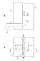
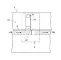
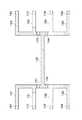
図1は、本発明の実施の形態に係るマイクロバルブ装置を備えるマイクロ化学システム用チップの構成を概略的に示す図であり、(a)は平面図を示し、(b)は図1(a)におけるIb−Ib線に沿う断面図を示す。 1A and 1B are diagrams schematically showing a configuration of a chip for a microchemical system including a microvalve device according to an embodiment of the present invention. FIG. 1A is a plan view, and FIG. ) Is a cross-sectional view taken along line Ib-Ib.
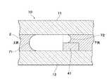
図2は、図1におけるバルブ流路の近傍における液体流路を説明する断面図である。 FIG. 2 is a cross-sectional view illustrating a liquid channel in the vicinity of the valve channel in FIG.
なお、図1及び図2は、本発明の実施の形態に係るマイクロバルブ装置の近傍のみを示しており、各流路(後述する液体流路2及びバルブ流路31)は、マイクロ化学システム用チップの基材の上面に対して、実質的に平行となるように形成されている。 1 and 2 show only the vicinity of the microvalve device according to the embodiment of the present invention, and each flow path (a
図1及び図2において、マイクロ化学システム用チップ1は、液体流路2を有する基材10と、基材10の内部に形成されたマイクロバルブ装置3とを備える。液体流路2の下流側に、液体流路2の断面積を小さくする堰41が形成されている。 1 and 2, the microchemical system chip 1 includes a
基材10は、液体流路2、堰41、及び後述するバルブ流路31が表面に形成されるチャネル部材12と、チャネル部材12を覆うカバー部材11とから成る。ここで、堰41とバルブ流路31との距離はL(図1)で表され、この距離Lは100μm以下である。 The
基材10は、親水基を有するガラス、例えば、ソーダライムガラス、アルミノ硼珪酸ガラス、アルミノ珪酸ガラス、無アルカリガラス、石英ガラス等が好適に用いられ、実質的に均等な厚みを有し、水平に配置されている。 As the
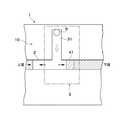
マイクロバルブ装置3は、合流部32で液体流路2に交差するバルブ流路31から成るバルブ流路構造と、制御用流体を接続構造51及び接続孔6を介してバルブ流路31に供給する流体制御機構5とを有する。制御用流体としては、液体流路2を流れる液体と混ざらず、かつ、反応しない流体(例えば、空気)を用いることが望ましい。また、流体制御機構5としては、ポンプやシリンジなど、流体を注入する機能を有するものを用いることができる。 The
バルブ流路31の形状は、断面形状が半円形状のものの他、矩形状等、目的に応じて適宜選択可能である。また、バルブ流路31と液体流路2の形状は同一形状としてもよいし、異なる形状としてもよい。 The shape of the
さらに、図2において、合流部32により規定された液体流路2の空隙の高さをR1、堰41により規定された液体流路の空隙の高さをR2とする。そして、液体流路2の液体に対する接触角(正確には、制御流体中における液体流路2の液体に対する接触角)をθとし、液体の表面張力をσとする。さらに、液体流路2の上流側からの圧力(通常、大気圧と、シリンジ及びマイクロ化学システム用チップを繋げるチューブによる圧力約3000Paとの合計)をP1、下流側からの圧力(通常、大気圧)をP2とするとき、圧力差P1−P2(通常、約3000Pa)をΔPとする。このとき圧力差ΔPは、
ΔP=2・σ・cosθ・(1/R2/2−1/R1/2)=2・σ・cosθ・(2/R2−2/R1)=4・σ・cosθ・(1/R2−1/R1)で表される。Further, in FIG. 2, the height of the gap of the
ΔP = 2 · σ · cos θ · (1 / R2 / 2-1 / R1 / 2) = 2 · σ · cos θ · (2 / R2-2 / R1) = 4 · σ · cos θ · (1 / R2-1 / R1).
堰41により規定された液体流路の空隙の高さR2は、圧力差ΔPを押し返す必要があるので、
R2<1/(ΔP/(4・σ・cosθ)+1/R1)
すなわち、
R2<4・σ・cosθ・R1/(ΔP・R1+4・σ・cosθ)
となる。Since the height R2 of the gap of the liquid channel defined by the
R2 <1 / (ΔP / (4 · σ · cos θ) + 1 / R1)
That is,
R2 <4 · σ · cos θ · R1 / (ΔP · R1 + 4 · σ · cos θ)
It becomes.
液体が水(表面張力σ=76×10−3N/m2)、制御流体が空気、液体(水)と液体流路2の接触角θが30度、圧力差ΔPが3000Paのとき、R1=100μm(100×10−6m)ならばR2≦46.7μm、R1=50μm(50×10−6m)ならばR2≦31.8μmとなる。When the liquid is water (surface tension σ = 76 × 10−3 N / m2 ), the control fluid is air, the contact angle θ between the liquid (water) and the
また、液体としてエタノール(表面張力σ=24×10−3N/m2)を用いて、他の条件を同じにした場合は、R1=100μm(100×10−6m)ならばR2≦21.6μm、R1=50μm(50×10−6m)ならばR2≦17.8μmとなる。Further, when ethanol (surface tension σ = 24 × 10−3 N / m2 ) is used as the liquid and the other conditions are the same, if R1 = 100 μm (100 × 10−6 m), R2 ≦ 21 If .6 μm and R1 = 50 μm (50 × 10−6 m), then R2 ≦ 17.8 μm.
なお、液体流路2における矢印は液体の流れ方向を示し、バルブ流路31における矢印は制御用流体の流れ方向を示す。 The arrow in the
以下、図1のマイクロ化学システム用チップ1の製造方法を説明する。 Hereinafter, a method for manufacturing the microchemical system chip 1 of FIG. 1 will be described.
一般的な溝加工方法として、エッチング法、ドリルによる切削法、サンドブラスト法、及びレーザー加工法等があるが、ガラスの溝加工方法としては、フッ酸を主成分とするエッチング液を用いたエッチング法が好適に用いられる。 As a general groove processing method, there are an etching method, a cutting method with a drill, a sand blasting method, a laser processing method, etc., but as a glass groove processing method, an etching method using an etchant mainly containing hydrofluoric acid. Are preferably used.
堰41の形成法としては、まず、液体流路2における堰41が形成される部分をマスクしておき、その他の液体流路2の部分をエッチングした後に、堰41が形成される部分のマスクを剥がして適当量エッチングする二段エッチング法や、レーザー照射で部分的にエッチング速度を早くすることにより段差の付いたエッチングを行う方法等がある。また、液体流路2の深さよりも低い高さの部材をチャネル部材12又はカバー部材11に後着けすることにより堰41を形成してもよい。 As a method for forming the
また、カバー部材11の表面には孔開け加工により接続孔6(図4)としての貫通孔を開ける。この孔開け加工には、ドリルによる掘削加工やレーザー加工等を好適に用いることができる。 Further, a through-hole as a connection hole 6 (FIG. 4) is formed on the surface of the
上述の方法で加工されたチャネル部材12とカバー部材11とを貼り合わせ、マイクロバルブ装置3を備えるマイクロ化学システム用チップ1を作製する。 The
以下、マイクロ化学システム用チップ1の制御方法を図3〜10を用いて説明する。なお、図4〜10において、斜線部分は液体を表す。 Hereinafter, a method for controlling the microchemical system chip 1 will be described with reference to FIGS. 4 to 10, the hatched portion represents a liquid.
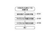
図3は、図1のマイクロ化学システム用チップ1の制御方法を示すフローチャートである。 FIG. 3 is a flowchart showing a method for controlling the microchemical system chip 1 of FIG.
基本的には、図3のフローチャートに示したフローに従うことによって、液体流路2を流れる液体の遮断及び開放を行うことができる。 Basically, by following the flow shown in the flowchart of FIG. 3, the liquid flowing through the
図3において、まず、バルブ流路31へ供給される制御流体の供給圧力が一定になるように制御し、図4及び図5に示すように液体供給機構(不図示)により液体流路2へ液体を供給する(ステップS101)。制御流体の供給圧力は液体流路2へ供給される液体の流れに影響を与えない程度に適宜調整される。なお、図4中の液体流路2における矢印は、液体の流れ方向を示す。 In FIG. 3, first, the supply pressure of the control fluid supplied to the
液体流路2に液体が流れている状態(図4及び図5)で、バルブ流路31に供給される制御流体の圧力を高くすると(図6)、バルブ流路31における矢印方向(図6)に制御流体が供給され、液体と制御流体との界面60がバルブ流路31から液体流路2へ押しやられ(図7)、合流部32周辺において、液体流路2を流れる液体の圧力とバルブ流路31から液体流路2に流れ込んだ制御流体の圧力との圧力差により、液体の遮断が開始される。バルブ流路31への制御流体の供給がさらに進んで制御流体がバルブ流路31から液体流路2に流れ込むと、図8及び図9に示すように、液体流路2における液体の流れが遮断される(ステップS102)。 When the pressure of the control fluid supplied to the
液体の流れが遮断されたときに、液体の供給が停止されていないと、合流部32より上流側の液体流路2は加圧されたままであるが、下流側の液体流路2の圧力は0Paに近くなる。従って、液体流路2における合流部32の上流側及び下流側で液体流路2の深さが同じであれば、上流側の二層界面71よりも下流側の二層界面72がより強く液体流路2の下流側に押しやられてしまう。そこで、液体流路2の下流側に堰41を設けて、合流部32により規定された液体流路2の空隙の高さをR1、堰41により規定された液体流路2の空隙の高さをR2、液体流路2の液体に対する接触角をθ、液体の表面張力をσ、液体流路2の上流側からの圧力をP1、液体流路2の下流側からの圧力をP2、圧力P1と圧力P2との差P1−P2をΔPとするとき、堰41により規定された液体流路2の空隙の高さR2がR2<4・σ・cosθ・R1/(ΔP・R1+4・σ・cosθ)を満たすようにコントロールすることにより、液体流路2の深さが浅い(断面積が小さい)下流側部分に、より大きなラプラス圧を発生させて、液体流路2の上流側からの圧力に抗して下流側への制御流体の流れを抑制する。なお、液体流路2の内壁は液体に対する接触角を小さくするほど(30度以下)、即ち、液体に対する親和性が高いほど、下流側への制御流体の流れを抑制する効果を大きくすることができ、もってエアバルブとしての効果を大きくすることができる。よって、基材10がガラスの場合は、マイクロ化学システム用チップ1の作製後に液体流路2の内壁に薄いフッ酸等を一度通す等して親水処理をすることが好ましい。 If the supply of the liquid is not stopped when the flow of the liquid is interrupted, the
なお、液体流路2の液体の流れが遮断された後は、液体供給機構(不図示)から液体流路2への液体の供給を維持しても良いし、停止しても良い。 In addition, after the flow of the liquid in the
液体供給機構(不図示)から液体流路2への液体の供給を停止せずに維持する場合は、流体制御機構5からバルブ流路31への制御流体の供給圧力(マイクロバルブ装置3の圧力)を、マイクロバルブ装置3を閉鎖する(ステップS102)前の圧力に戻すことにより、液体が液体流路2を再び流れるようになる(ステップS103)。 When maintaining the supply of liquid from the liquid supply mechanism (not shown) to the
マイクロバルブ装置3により液体流路2における液体の流れが遮断されている状態から、マイクロバルブ装置3の圧力を、マイクロバルブ装置3を閉鎖する前の圧力に戻して、再び液体が液体流路2を流れるまでの過程を図10から図13を用いて説明する。 From the state where the liquid flow in the
マイクロバルブ装置3の圧力を、閉鎖前の圧力に戻すと、上流側からの圧力及び表面張力によって液体及び制御流体はバルブ流路31側に押し戻されるが(図10及び図11)、下流側の堰41とバルブ流路31との距離が100μmより大きいと、制御流体がバルブ流路31側に十分に押し戻された状態(図13)にはならず、制御流体の一部が液体流路2に残ってしまう(図12)。 When the pressure of the
本実施の形態のマイクロバルブ装置3によれば、液体流路2の深さが浅い(断面積が小さい)部分を規定する堰41が、液体流路2における合流部32の下流側に設置されるので、合流部32が規定する液体流路2の部分に比べて、堰41が規定する液体流路2のラプラス圧が高くなる。よって、液体流路2の上流側からの圧力に抗して制御用流体を堰41で停止させることができ、もって、液体流路2における合流部32に存在していた制御用流体をすべてバルブ流路31側に引き戻すことができ、制御用流体を液体流路2の下流側に流してしまうことはない。 According to the
また、本実施の形態のマイクロバルブ装置3によれば、制御用流体を供給する流体制御機構5以外は、液体流路2と同様に溝構造のみから成るので、上述した特許文献1のように機械的に可動する微細な弁構造体をバルブ流路3内に設ける必要がない。また、本実施の形態のマイクロバルブ装置3によれば、構造が簡単であり、故障しにくく、機械的な摩擦等により劣化することがないので、気密性を維持することができる。 Further, according to the
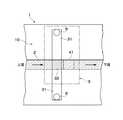
本実施の形態では、堰41が液体流路2における合流部32の下流側に設置されているが、これに限定されるものではなく、液体流路2を流れる液体にかかる圧力に応じて、液体流路2における合流部32の上流側に設置してもよく、後述する図14乃至図16で示すように、液体流路2における合流部32の上流側及び下流側の両方に設置してもよい。 In the present embodiment, the
本実施の形態では、接続孔6が1箇所に設けられているが、これに限定されるものではなく、複数箇所に設けられていてもよい。 In the present embodiment, the
以下に、本発明に係る実施例1乃至4を具体的に説明する。 Examples 1 to 4 according to the present invention will be specifically described below.
本実施例1乃至4では、液体流路2に供給する液体を水とし、バルブ流路3に供給する制御用流体を空気とし、基材10を水平に配置して、液体流路2及びバルブ流路3を実質的に水平にしている。 In the first to fourth embodiments, the liquid supplied to the
実施例1において、図1及び図2に示す構造のガラス製マイクロ化学システム用チップ1を用いた。液体流路2及びバルブ流路31を幅120μm、深さ50μmとし、堰41が規定する液体流路2の深さを20μmとした。 In Example 1, the glass microchemical system chip 1 having the structure shown in FIGS. 1 and 2 was used. The
図3のフローに従って、マイクロバルブ装置3の閉鎖及び開放を行い、液体流路2における水の流れを遮断し、再び開放することを試みた。 According to the flow of FIG. 3, the
液体流路2へ水を流し続けたところ(ステップS101)、液体流路2の両端における水圧差は3000Paであった。 When water was continuously supplied to the liquid channel 2 (step S101), the water pressure difference at both ends of the
次いで、シリンジ等の流体制御機構5を用いてバルブ流路31へ空気を供給したところ、液体流路2における水の流れが遮断された(ステップS102)。 Next, when air was supplied to the
次いで、バルブ流路31における空気を流体制御機構5側に移動させたところ、液体流路2における水の流れは再開し、遮断前の状態に戻った(ステップS103)。 Next, when the air in the
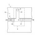
また、実施例2について図15及び図16を用いて説明する。 A second embodiment will be described with reference to FIGS. 15 and 16.
実施例2において、液体流路2における合流部32の上流側及び下流側の両方に堰42,41が設置されたガラス製マイクロ化学システム用チップ1を用いた。液体流路2及びバルブ流路31を幅120μm、深さ50μmとし、堰42,41が規定する液体流路2の深さを20μmとした。 In Example 2, the glass microchemical system chip 1 in which the
図3のフローに従って、マイクロバルブ装置3の閉鎖及び開放を行い、液体流路2における水の流れを遮断し、再び開放することを試みた。 According to the flow of FIG. 3, the
液体流路2へ水を流し続けたところ(ステップS101)、液体流路2の両端における水圧差は3000Paであった。 When water was continuously supplied to the liquid channel 2 (step S101), the water pressure difference at both ends of the
次いで、シリンジ等の流体制御機構5を用いてバルブ流路31へ空気を供給したところ、液体流路2における水の流れが遮断された(ステップS102)。 Next, when air was supplied to the
次いで、バルブ流路31における空気を流体制御機構5側に移動させたところ、液体流路2における水の流れは再開し、遮断前の状態に戻った(ステップS103)。 Next, when the air in the
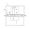
また、実施例3について図17を用いて説明する。 Example 3 will be described with reference to FIG.
実施例3において、2つのバルブ流路31を有するガラス製マイクロ化学システム用チップ1を用いた。液体流路2及びバルブ流路31を幅220μm、深さ100μmとし、堰41が規定する液体流路2の深さを30μmとした。 In Example 3, a glass microchemical system chip 1 having two
図3のフローに従って、マイクロバルブ装置3の閉鎖及び開放を行い、液体流路2における水の流れを遮断し、再び開放することを試みた。 According to the flow of FIG. 3, the
液体流路2へ水を流し続けたところ(ステップS101)、液体流路2の両端における水圧差は3000Paであった。 When water was continuously supplied to the liquid channel 2 (step S101), the water pressure difference at both ends of the
次いで、シリンジ等の流体制御機構5を用いてバルブ流路31へ空気を供給したところ、液体流路2における水の流れが遮断された(ステップS102)。 Next, when air was supplied to the
次いで、バルブ流路31における空気を流体制御機構5側に移動させたところ、液体流路2における水の流れは再開し、遮断前の状態に戻った(ステップS103)。 Next, when the air in the
さらに、実施例4について図18乃至図20を用いて説明する。 Further, Example 4 will be described with reference to FIGS.
図18乃至図20は、本発明の実施の形態に係るマイクロバルブ装置3を応用した流路切換チップの構成を概略的に示す平面図である。 18 to 20 are plan views schematically showing the configuration of the flow path switching chip to which the
図18に示すように、制御流路131,132,133,134内の空気圧が低い場合は、液体流路121,122,123,124へは空気は流れ込まず、接続孔161,162から供給された水は液体流路125を通って液体流路123,124に流れ込み、接続孔163,164に達する。 As shown in FIG. 18, when the air pressure in the
また、図19に示すように、接続孔172,174における空気圧を上げた場合、空気は液体流路122,124に流れ込む。この場合であっても、堰142,144で空気は止まるため、液体流路125及び液体流路121,123へは空気は流れ込まない。また、接続孔172から導入された空気によって液体流路122内の水の流れは遮断されるため、接続孔161から導入した水のみが液体流路121から液体流路125に流れ込む。さらに、接続孔174から導入された空気によって液体流路124が遮断されるため、液体流路125から流れてきた水は液体流路123を通って接続孔163に達する。 As shown in FIG. 19, when the air pressure in the connection holes 172 and 174 is increased, the air flows into the
さらに、図20に示すように、接続孔172,173から導入する空気の圧力を接続孔161,163から導入する水の圧力よりも同等か低めに設定し、接続孔171,174における空気圧を上げた場合、空気は液体流路121,124に流れ込む。この場合であっても、堰141,144で空気は止まるため、液体流路125及び液体流路122,123へは空気は流れ込まない。接続孔171から導入された空気によって液体流路121内の水の流れは遮断されるため、接続孔162から導入した水のみが液体流路122から液体流路125に流れ込む。さらに、接続孔174から導入された空気によって液体流路124が遮断されるため、液体流路125から流れてきた水は液体流路123を通って接続孔163に達する。 Further, as shown in FIG. 20, the pressure of air introduced from the connection holes 172 and 173 is set to be equal to or lower than the pressure of water introduced from the connection holes 161 and 163, and the air pressure in the connection holes 171 and 174 is increased. In this case, air flows into the
このように、個々の接続孔にかける圧力を制御することによって、液体導入部分と液体導出部分を任意に選択することができる。 In this way, by controlling the pressure applied to each connection hole, the liquid introduction part and the liquid lead-out part can be arbitrarily selected.
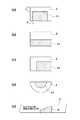
本実施の形態では、液体流路2の下流側に液体流路2の断面積を小さくする堰41が形成されているが、堰41の形状は特に限定されるものではなく、液体の流れ方向から見た断面形状が、例えば、図21(a)乃至(d)に示すような形状であってもよく(但し、図21(a)において、長さaは長さbよりも大きい)、液体の流れ方向と垂直な方向から見た断面形状が、例えば、図21(e)に示すような形状であってもよい。 In the present embodiment, the
1 マイクロ化学システム用チップ
2 液体流路
3 マイクロバルブ装置
5 流体制御機構
6 接続孔
10 基材
11 カバー部材
12 チャネル部材
31 バルブ流路
32 合流部
41 堰
51 接続構造DESCRIPTION OF SYMBOLS 1 Microchemical system chip |
Claims (6)
Translated fromJapanese前記バルブ流路構造を流れる制御用流体を前記バルブ流路構造に接続された液体流路に供給することによって、前記液体流路を流れる液体を遮断及び開放するマイクロバルブ装置であって、
前記バルブ流路構造は合流部で前記液体流路と交差するバルブ流路から成り、
前記液体流路における前記合流部の上流側及び下流側の少なくとも一方に前記液体流路の断面積を小さくする堰が設置されたことを特徴とするマイクロバルブ装置。A fluid control mechanism for supplying a control fluid; and a valve channel structure through which the supplied control fluid flows,
A microvalve device that shuts off and opens the liquid flowing through the liquid flow path by supplying a control fluid flowing through the valve flow path structure to a liquid flow path connected to the valve flow path structure;
The valve channel structure consists of a valve channel that intersects the liquid channel at the junction,
A microvalve device characterized in that a weir for reducing the cross-sectional area of the liquid flow path is installed on at least one of the upstream side and the downstream side of the junction in the liquid flow path.
R2<4・σ・cosθ・R1/(ΔP・R1+4・σ・cosθ)。The height of the gap of the liquid channel defined by the junction is R1, the height of the gap of the liquid channel defined by the weir is R2, the contact angle of the liquid channel with respect to the liquid is θ, and the liquid When the surface tension of σ is σ, the pressure from the upstream side of the liquid flow path is P1, the pressure from the downstream side of the liquid flow path is P2, and the difference P1-P2 between the pressure P1 and the pressure P2 is ΔP, The microvalve device according to any one of claims 1 to 3, wherein the height R2 of the gap of the liquid channel defined by the weir satisfies the following formula:
R2 <4 · σ · cos θ · R1 / (ΔP · R1 + 4 · σ · cos θ).
Priority Applications (1)
| Application Number | Priority Date | Filing Date | Title |
|---|---|---|---|
| JP2006057667AJP2007232172A (en) | 2006-03-03 | 2006-03-03 | Microvalve device |
Applications Claiming Priority (1)
| Application Number | Priority Date | Filing Date | Title |
|---|---|---|---|
| JP2006057667AJP2007232172A (en) | 2006-03-03 | 2006-03-03 | Microvalve device |
Publications (1)
| Publication Number | Publication Date |
|---|---|
| JP2007232172Atrue JP2007232172A (en) | 2007-09-13 |
Family
ID=38552958
Family Applications (1)
| Application Number | Title | Priority Date | Filing Date |
|---|---|---|---|
| JP2006057667AWithdrawnJP2007232172A (en) | 2006-03-03 | 2006-03-03 | Microvalve device |
Country Status (1)
| Country | Link |
|---|---|
| JP (1) | JP2007232172A (en) |
Cited By (4)
| Publication number | Priority date | Publication date | Assignee | Title |
|---|---|---|---|---|
| WO2013011652A1 (en)* | 2011-07-20 | 2013-01-24 | 株式会社エンプラス | Fluid handling device, fluid handling method, and fluid handling system |
| JP2015143708A (en)* | 2009-11-24 | 2015-08-06 | オプコ・ダイアグノスティクス・リミテッド・ライアビリティ・カンパニーOpko Diagnostics,Llc | Fluid mixing and delivery in microfluidic systems |
| US9901924B2 (en) | 2011-07-14 | 2018-02-27 | Enplas Corporation | Fluid handling device, fluid handling method, and fluid handling system |
| JP2022167074A (en)* | 2021-04-22 | 2022-11-04 | 株式会社東芝 | Channel structure, fluid agitating method, and method of manufacturing lipid particles |
- 2006
- 2006-03-03JPJP2006057667Apatent/JP2007232172A/ennot_activeWithdrawn
Cited By (10)
| Publication number | Priority date | Publication date | Assignee | Title |
|---|---|---|---|---|
| JP2015143708A (en)* | 2009-11-24 | 2015-08-06 | オプコ・ダイアグノスティクス・リミテッド・ライアビリティ・カンパニーOpko Diagnostics,Llc | Fluid mixing and delivery in microfluidic systems |
| US9555408B2 (en) | 2009-11-24 | 2017-01-31 | Opko Diagnostics, Llc | Fluid mixing and delivery in microfluidic systems |
| US9861980B2 (en) | 2009-11-24 | 2018-01-09 | Opko Diagnostics, Llc | Fluid mixing and delivery in microfluidic systems |
| US10953398B2 (en) | 2009-11-24 | 2021-03-23 | Opko Diagnostics, Llc | Fluid mixing and delivery in microfluidic systems |
| US9901924B2 (en) | 2011-07-14 | 2018-02-27 | Enplas Corporation | Fluid handling device, fluid handling method, and fluid handling system |
| WO2013011652A1 (en)* | 2011-07-20 | 2013-01-24 | 株式会社エンプラス | Fluid handling device, fluid handling method, and fluid handling system |
| JPWO2013011652A1 (en)* | 2011-07-20 | 2015-02-23 | 株式会社エンプラス | Fluid handling device, fluid handling method and fluid handling system |
| US9527078B2 (en) | 2011-07-20 | 2016-12-27 | Enplas Corporation | Fluid handling device, fluid handling method, and fluid handling system |
| JP2022167074A (en)* | 2021-04-22 | 2022-11-04 | 株式会社東芝 | Channel structure, fluid agitating method, and method of manufacturing lipid particles |
| JP7590261B2 (en) | 2021-04-22 | 2024-11-26 | 株式会社東芝 | Flow channel structure, fluid agitation method, and lipid particle manufacturing method |
Similar Documents
| Publication | Publication Date | Title |
|---|---|---|
| US20060289309A1 (en) | Microchemical system | |
| US7513273B2 (en) | Fluid flow control device | |
| Wang et al. | Controlling flow behavior of water in microfluidics with a chemically patterned anisotropic wetting surface | |
| Thompson et al. | Adhesive-based bonding technique for PDMS microfluidic devices | |
| US7735522B2 (en) | Fluid flow control device | |
| Ellinas et al. | Superhydrophobic, passive microvalves with controllable opening threshold: Exploiting plasma nanotextured microfluidics for a programmable flow switchboard | |
| US20030005967A1 (en) | Microfluidic metering systems and methods | |
| US8343425B1 (en) | Multi-layer micro/nanofluid devices with bio-nanovalves | |
| WO2012042060A1 (en) | Microfluidic device for production and collection of droplets of a fluid | |
| CN102344111A (en) | A process for manufacturing a micromechanical structure having a buried area provided with a filter | |
| JP2009236555A (en) | Fluid device and manufacturing method thereof | |
| JP2007232172A (en) | Microvalve device | |
| JP2007523355A (en) | Microfluidic device and diagnostic and analytical apparatus including the same | |
| US7299818B2 (en) | Integrated microvalve and method for manufacturing a microvalve | |
| CN101290314A (en) | Microfluidic chip for cell fixation and solution dilution | |
| KR100838129B1 (en) | Microfluidic device and diagnostic and analysis device having the same | |
| US8540416B2 (en) | Fluidic flow merging apparatus | |
| JP2006183818A (en) | Microvalve device and its control method | |
| JP2006029485A (en) | Microvalve and microfluidic device having the valve | |
| WO2003062137A3 (en) | Method of making a thick microstructural oxide layer and device utilizing same | |
| Li et al. | Texture-structure-based liquid metal filling for blind-end microchannels and its application on multi-layer chips | |
| JP7531891B2 (en) | Dispensing apparatus for microchannel and microchannel device | |
| JP2006142242A (en) | Micro liquid control device | |
| CN108212230B (en) | Droplet generation device and method based on micro-valve control | |
| JP2011025127A (en) | Microdevice |
Legal Events
| Date | Code | Title | Description |
|---|---|---|---|
| A300 | Withdrawal of application because of no request for examination | Free format text:JAPANESE INTERMEDIATE CODE: A300 Effective date:20090512 |