JP2007223002A - Working device and robot working method - Google Patents
Working device and robot working methodDownload PDFInfo
- Publication number
- JP2007223002A JP2007223002AJP2006048478AJP2006048478AJP2007223002AJP 2007223002 AJP2007223002 AJP 2007223002AJP 2006048478 AJP2006048478 AJP 2006048478AJP 2006048478 AJP2006048478 AJP 2006048478AJP 2007223002 AJP2007223002 AJP 2007223002A
- Authority
- JP
- Japan
- Prior art keywords
- work
- robot
- workpiece
- protective fence
- fence
- Prior art date
- Legal status (The legal status is an assumption and is not a legal conclusion. Google has not performed a legal analysis and makes no representation as to the accuracy of the status listed.)
- Pending
Links
Images


Classifications
- B—PERFORMING OPERATIONS; TRANSPORTING
- B25—HAND TOOLS; PORTABLE POWER-DRIVEN TOOLS; MANIPULATORS
- B25J—MANIPULATORS; CHAMBERS PROVIDED WITH MANIPULATION DEVICES
- B25J9/00—Programme-controlled manipulators
- B25J9/0093—Programme-controlled manipulators co-operating with conveyor means
- B—PERFORMING OPERATIONS; TRANSPORTING
- B25—HAND TOOLS; PORTABLE POWER-DRIVEN TOOLS; MANIPULATORS
- B25J—MANIPULATORS; CHAMBERS PROVIDED WITH MANIPULATION DEVICES
- B25J19/00—Accessories fitted to manipulators, e.g. for monitoring, for viewing; Safety devices combined with or specially adapted for use in connection with manipulators
- B25J19/06—Safety devices
- B—PERFORMING OPERATIONS; TRANSPORTING
- B25—HAND TOOLS; PORTABLE POWER-DRIVEN TOOLS; MANIPULATORS
- B25J—MANIPULATORS; CHAMBERS PROVIDED WITH MANIPULATION DEVICES
- B25J21/00—Chambers provided with manipulation devices
Landscapes
- Engineering & Computer Science (AREA)
- Robotics (AREA)
- Mechanical Engineering (AREA)
- Manipulator (AREA)
- Automatic Assembly (AREA)
- Auxiliary Devices For Machine Tools (AREA)
Abstract
Description
Translated fromJapanese本発明は、ワークに作業を施すロボットが保護柵で囲われている作業装置に関する。 The present invention relates to a working device in which a robot that performs work on a workpiece is surrounded by a protective fence.
ロボットは、省力化が図れる有益な自動機械である。ところで、ロボットの動作範囲に人が立ち入るためには、ロボットを停止させることが条件となる。しかし、ロボットの停止は生産性の低下に繋がる。そこで、ロボットの停止頻度を下げる技術が提案されている(例えば、特許文献1参照。)。
特許文献1を次図に基づいて説明する。
図5は従来の技術の基本構成を説明する図及びその作用図である。
(a)において、作業装置100は、ロボット101と、このロボット101の動作範囲Wに配置されワークを積載した第1及び第2コンテナ102、103と、この第1コンテナ及び第2コンテナ102、103の周囲に設ける保護柵104と、この保護柵104の一部に開閉可能に設けた第1扉104a及び第2扉104bと、これらの第1及び第2扉104a、104bの外側に設け、第1コンテナ及び第2コンテナ102、103を出し入れ可能にしたワーク供給エリア105、106とを備える。Patent document 1 is demonstrated based on the following figure.
FIG. 5 is a diagram for explaining the basic configuration of the prior art and its operation diagram.
In (a), the
動作範囲Wにおいて、ロボット101と第1コンテナ102の間に第1センサ107が設けられ、ロボット101と第2コンテナ103の間に第2センサ109が設けられている。
また、第1扉104aに、第1扉104aの開閉を検出する第1開閉センサ111が設けられ、第2扉104bに、第2扉104bの開閉を検出する第2開閉センサ112が設けられている。113は第1扉の作業可能表示灯、114は第2扉の作業可能表示灯、115はワーク搬送手段としてのスライダである。In the operation range W, a
The
(b)において、第1及び第2コンテナ102、103上に載せたワークは、ロボット101によって順次把持され、スライダ115へ搬送される。 In (b), the workpieces placed on the first and
コンテナ102のワークが空になると、作業者Pは、作業可能表示灯113が点灯していることを確認した上で、第1扉104aを開け、ワーク供給エリア105から第1コンテナ102を出し入れする。
すなわち、半円状の動作範囲Wのうちの斜線を施していない領域には、作業員Pが立ち入ることができる。ロボットを止める必要がないので、生産性を高めることができる。When the work in the
That is, the worker P can enter a region in the semicircular motion range W that is not shaded. Productivity can be increased because there is no need to stop the robot.
しかし、特許文献1の技術では、第1及び第2扉104a、104bの開閉を検出する第1及び第2開閉センサ111、112、センサ107、109、及び作業可能表示灯113、114など多数の要素が必要となり、作業装置100は複雑なものにならざるを得ない。また、装置費用も嵩む。
簡便な構造で、設備費用の嵩まない作業装置及び作業方法が望まれる。However, in the technique of Patent Document 1, there are a number of first and second opening /
There is a demand for a working device and a working method that have a simple structure and do not increase the equipment cost.
本発明は、簡便な構造をもち、低廉な費用で構成可能な作業装置及び作業方法を提供することを課題とする。 An object of the present invention is to provide a working device and a working method that have a simple structure and can be configured at low cost.
請求項1に係る発明は、第1ワーク及びこの第1ワークとは別の第2ワークに作業を施すロボットが保護柵で囲われている作業装置において、保護柵に、第2ワークを載せ、保護柵の外からロボットの動作範囲へ移動させる第2ワーク移動機構が付設されていることを特徴とする。 The invention according to claim 1 is a working device in which a robot that performs work on a first work and a second work different from the first work is surrounded by a protective fence, and the second work is placed on the protective fence. A second workpiece moving mechanism for moving the robot from the outside of the protective fence to the operating range of the robot is provided.
請求項2に係る発明では、第2ワーク移動機構は、保護柵に設けられている開口部を貫通して敷設されたレールと、このレールに移動可能に載せられ、開口部を塞ぐ大きさ及び形状に設定された前壁部及び後壁部を備えるトレイとからなることを特徴とする。 In the invention which concerns on Claim 2, a 2nd workpiece movement mechanism is a rail laid through the opening part provided in the protection fence, and the magnitude | size which is mounted on this rail so that movement is possible, and block | closes an opening part, It consists of a tray provided with the front wall part and back wall part which were set to the shape, It is characterized by the above-mentioned.
請求項3に係る発明は、第1ワーク及びこの第1ワークとは別の第2ワークに作業を施すロボットによる作業方法において、第1ワークにロボットで作業を施す第1作業工程と、この工程に並行してロボットの動作範囲にある、処理済みの第2ワークを保護柵の外へ移動する第2ワーク取り出し工程と、保護柵の外から未処理の第2ワークをロボットの動作範囲へ移動する第2ワーク投入工程と、第1作業工程と重ならないときに、第2ワークにロボットで作業を施す第2作業工程とからなり、第1ワークと第2ワークを共通のロボットで連続的に処理することを特徴とする。 According to a third aspect of the present invention, there is provided a work method by a robot for performing work on a first work and a second work different from the first work, a first work process for performing work on the first work by the robot, and this process. In parallel, the second workpiece removal step for moving the treated second workpiece outside the protection fence, which is within the robot movement range, and the untreated second workpiece from the outside of the protection fence to the robot movement range. And a second work process in which a robot works on the second work when it does not overlap with the first work process, and the first work and the second work are continuously connected by a common robot. It is characterized by processing.
請求項1に係る発明では、第2ワーク移動機構で、第2ワークを保護柵の外から内へ又は内から外へ移動させる。すなわち、人が保護柵内に入らないで、ロボットに第2ワークへ作業を行わせることができる。
人が保護柵内に入る必要がないので、人を検出するセンサやスイッチを省くことができ、簡便な構造をもち、低廉な費用で構成可能な作業装置を提供することができる。In the invention which concerns on Claim 1, a 2nd workpiece | work is moved to the inside from the outside of a protection fence, or from the inside to the outside with a 2nd workpiece movement mechanism. That is, it is possible to cause the robot to perform work on the second workpiece without entering the protective fence.
Since it is not necessary for a person to enter the protective fence, a sensor or switch for detecting the person can be omitted, and a working device that has a simple structure and can be configured at low cost can be provided.
請求項2に係る発明では、第2ワーク移動機構に、開口部を塞ぐ大きさ及び形状に設定された前壁部及び後壁部を備えた。保護柵の開口部を、前壁部又は後壁部で塞げば、開口部から人が手などを保護柵内へ入れることができなくなる。 In the invention which concerns on Claim 2, the 2nd workpiece movement mechanism was equipped with the front wall part and the rear wall part which were set to the magnitude | size and shape which block | close an opening part. If the opening of the protective fence is closed with the front wall or the rear wall, a person cannot put a hand or the like into the protective fence from the opening.
請求項3に係る発明では、第1作業工程と重ならないときに、第2ワークにロボットで作業を施す第2作業工程を備え、第1ワークと第2ワークを共通のロボットで連続的に処理するようにしたので、ロボットの稼働率を向上することができ、ロボットを有効に活用することができる。 In the invention which concerns on Claim 3, when it does not overlap with a 1st work process, it has the 2nd work process which works with a robot on a 2nd work, and processes a 1st work and a 2nd work continuously with a common robot As a result, the operation rate of the robot can be improved and the robot can be used effectively.
本発明を実施するための最良の形態を添付図に基づいて以下に説明する。なお、図面は符号の向きに見るものとする。
図1は本発明に係る作業装置の斜視図であり、作業装置10は、ロボット11と、ロボットアーム13の先端13aに取り付けるシール剤塗布ユニット14と、ロボット11の周囲に設け第1ワーク15を搬送する第1コンベヤ16と、同じく、ロボット11の周囲に設け第2ワーク18を取り出し又は取り入れる第2ワーク移動機構19と、ロボット11、第1コンベヤ16及び第2ワーク移動機構19を囲う保護柵21とを備える装置である。The best mode for carrying out the present invention will be described below with reference to the accompanying drawings. The drawings are viewed in the direction of the reference numerals.
FIG. 1 is a perspective view of a working device according to the present invention. The
すなわち、作業装置10は、第1ワーク15及びこの第1ワーク15とは別の第2ワーク18に作業を施すロボット11が保護柵21で囲われている装置である。保護柵21には、第2ワーク18を載せ、保護柵21の外からロボット11の動作範囲へ移動させる第2ワーク移動機構19が付設されている。 That is, the
図2は本発明に係る作業装置の平面図であり、作業装置10は、ロボット11が作業可能な領域である動作範囲Kに第1ワーク15を搬送する第1コンベヤ16を設け、第1ワーク15とは別部品である第2ワーク18、18を動作範囲Kに移動させる第2ワーク移動機構19を設けるとともに、動作範囲Kを保護柵21で囲ってなる。 FIG. 2 is a plan view of the working device according to the present invention. The
ロボット11は、ロボット本体12と、このロボット本体12から延ばしたロボットアーム13と、このロボットアーム13の先端に設けるシール剤塗布ユニット14からなり、保護柵21内の動作範囲Kにおいて、ロボットアーム13を移動させながらシール剤塗布ユニット14からワークの表面にシール剤を塗布する。 The
保護柵21は、ロボット11の周囲を囲うものであり、ロボット11の動作範囲Kは、保護柵21内側の範囲ということができる。保護柵21は、平面視長方形に形成し、第1柵〜第4柵21a、21b、21c、21dからなる。第1柵21aに対向させて第3柵21cを設け、第2柵21bに対向させて第4柵21dを設ける。 The
第1柵21aと第3柵21cに第1コンベヤ16が通る第1開口24及び第2開口25を設け、第3柵21cに第2ワーク移動機構19が通る第3開口26を設け、第1及び第2ワーク15、18を動作範囲Kに出し入れ可能に構成する。 A first opening 24 and a second opening 25 through which the
第1コンベヤ16は、機体28と、この機体28上に複数配置するローラ部材29・・・(・・・は複数を示す。以下同じ。)を備える。ローラ部材29・・・は、図示せぬ駆動手段によって駆動され、ワークを載置する板状のパレット31・・・を図矢印S方向に移動させる。 The
第2ワーク移動機構19は、第3開口26を貫通して設ける基台41と、この基台41上に敷設したレール42、42と、これらのレール42、42に沿って移動可能に設けるトレイ43とからなる。基台41は、第3開口26を横断して保護柵21の内側に張り出して設けるものである。 The second
トレイ43は、第3開口26を塞ぐ大きさ及び形状に設定された前壁部44及び後壁部45と、前壁部44の外側の面に設けトレイ43を操作する操作部48と、トレイ43の側方を塞ぐ左右の側壁部46L、46Rと、トレイ43上に2つ載せる第2ワーク18、18を仕切るとともにこれらの位置決めを行う仕切板47と、からなる。 The
第2ワーク移動機構19は、レール42、42に移動可能に載せられ、開口部22の1つである第3開口26を塞ぐ大きさ及び形状に設定された前壁部44及び後壁部45を備えた。保護柵21の開口部22を、前壁部44又は後壁部45で塞げば、開口部22から人が手などを保護柵21内へ入れることができなくなる。 The second
以上に述べた作業装置の作用を次に述べる。
パレット31・・・に載置した第1ワーク15・・・が、第1開口24から保護柵21内に搬送され、第1コンベヤ16上の所定位置に到達する。そして、ロボット11が第1ワーク15表面の所定位置にシール剤の塗布を開始する。The operation of the working device described above will be described next.
The
ロボット11が第1ワーク15にシール剤を塗布する間、保護柵21内に張り出して設ける基台41上に設定した範囲にロボット11はなく、作業者Pが第2ワーク移動機構19のトレイ43を移動させても、ロボット11は停止することなく、シール剤塗布作業を続ける。次図で、第2ワーク移動機構19の作用について説明する。 While the
図3は第2ワーク移動機構の作用説明図である。
(a)は、第1ワークにロボットで作業を施すときに、この作業に並行して、ロボットの動作範囲にある、処理済みの第2ワーク18b、18bを保護柵の外へ移動する第2ワーク取り出し工程を説明する図である。この工程において、作業者Pは、トレイ43の操作部48をつかんで引き出し、処理済みの第2ワーク18b、18bを取り出す。FIG. 3 is an operation explanatory diagram of the second workpiece moving mechanism.
(A) is a second process of moving the processed
(b)は、保護柵の外から未処理の第2ワーク18a、18aをロボットの動作範囲へ移動する第2ワーク投入工程を説明する図である。この工程において、作業者Pは、未処理の第2ワーク18a、18aをトレイ43に入れ、この操作部48をつかんで押し、第2ワーク18a、18aをロボット11の動作範囲内に移動させる。
(c)は、第1作業工程と重ならないときに、第2ワーク18a、18aにロボットで作業を施す第2作業工程を説明する図である。
この工程において、ロボットで第2ワーク18a、18aにシール剤塗布作業を施す。
このとき、トレイ43が完全に閉じている条件にのみ、動作範囲Kで且つ保護柵21の基台41上に移動でき、それ以外の条件では、基台41上に侵入しないようにロボット11の動きを制御する。(B) is a figure explaining the 2nd workpiece | work injection | throwing-in process which moves unprocessed 2nd workpiece |
(C) is a figure explaining the 2nd work process which works with the
In this step, the robot applies a sealant application operation to the
At this time, only when the
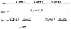
図4は本発明に係る作業装置のタイムチャートであり、横軸は時間を示す。
ロボットによる作業方法は、ロボットが第1ワークに作業を施す第1作業工程と、この工程に並行して処理済みの第2ワークを保護柵の外へ移動する第2ワーク取り出し工程と、保護柵の外から未処理の第2ワークをロボットの動作範囲へ移動する第2ワーク投入工程と、第1作業工程と重ならないときに、第2ワークに前記ロボットで作業を施す第2作業工程と、第2作業工程と並行して第1コンベヤでパレットを移動させ、加工済みの第1のワークを払い出すとともに未加工の第1のワークを動作範囲内における所定の位置に搬入するパレット移動工程とからなる。FIG. 4 is a time chart of the working device according to the present invention, and the horizontal axis indicates time.
The robot working method includes a first work process in which the robot performs work on the first work, a second work take-out process in which the processed second work is moved out of the protective fence in parallel with this process, and a protective fence. A second workpiece input step of moving an unprocessed second workpiece from outside the robot to an operation range of the robot, a second operation step of performing an operation on the second workpiece by the robot when not overlapping with the first operation step, A pallet moving step in which the pallet is moved by the first conveyor in parallel with the second work step, the processed first workpiece is discharged, and the unprocessed first workpiece is carried to a predetermined position within the operation range; Consists of.
このような方法を採ることで、第1ワークの搬送時などロボットが第1ワークにシール剤塗布作業をしないときのロボットの待ち時間を、第2ワークの作業に振り向けることができる。
すなわち、第1作業工程と重ならないときに、第2ワークにロボットで作業を施す第2作業工程を備え、第1ワークと第2ワークを共通のロボットで連続的に処理するようにしたので、ロボットの稼働率を向上することができ、ロボットを有効に活用することができる。By adopting such a method, the waiting time of the robot when the robot does not apply the sealant to the first workpiece such as when the first workpiece is transferred can be directed to the operation of the second workpiece.
That is, when it does not overlap with the first work process, it has a second work process in which the second work is performed by a robot, and the first work and the second work are continuously processed by a common robot. The operating rate of the robot can be improved, and the robot can be used effectively.
本実施例において、第1ワーク(図2の符号15)はエンジンのシリンダブロックであり、第2ワーク(図2の符号18)は同一のエンジンに用いる小物部品であり、これらを1つのシール剤塗布ユニットで処理することができる。また、シール剤を塗布した後のワークは、シール剤が固まる前に組み付けることが必要なものである。いわゆる、ワークの造り溜めは許されず、速やかに組付作業をさせる必要があった。本発明の作業装置は、このような条件の下での生産に好適である。 In this embodiment, the first work (
図2に戻って、保護柵21に、第2ワーク18を載せ、保護柵21の外からロボット11の動作範囲Kへ移動させる第2ワーク移動機構19が付設されている。
仮に、ロボット11に人を介在させる作業を含んでいる場合、ロボット11の稼働率をできるだけ低下させないようにするため、扉の開閉検出手段及びロボット11の周囲にセンサなどの要素を設け、所定の条件を満たしたとき一部の範囲でのみ人を介在させる。このため、ロボット11の稼働率の低下は回避できるものの、作業者Pを保護する要素が増え、作業装置10は複雑なものにならざるを得ない。Returning to FIG. 2, a second
If the
この点、本発明では、保護柵21に、第2ワーク18を載せ、保護柵21の外からロボットの動作範囲Kへ移動させる第2ワーク移動機構19を付設するので、ロボット11の動作範囲に作業者Pを介在させない作業装置を構成することが可能となる。動作範囲に作業者を介在させることのない作業装置を構成することができる。 In this regard, in the present invention, since the
すなわち、人が保護柵21内に入らないで、ロボット11に第2ワーク18へ作業を行わせることができる。
作業者が保護柵内に入る必要がないので、作業者を検出するセンサやスイッチを省くことができ、簡便な構造をもち、低廉な費用で構成可能な作業装置を提供することができる。That is, the
Since it is not necessary for the worker to enter the protective fence, a sensor or switch for detecting the worker can be omitted, and a working device that has a simple structure and can be configured at low cost can be provided.
尚、本発明は、実施の形態ではシリンダブロックのシール剤塗布装置に適用したが、車体組立工程における、ドア部材及び小物部品へのシール剤塗布に適用可能であり、それ以外の一般の生産ライン上において、ワークにシール剤を塗布する工程に適用することは差し支えない。 Although the present invention is applied to the cylinder block sealant application device in the embodiment, it can be applied to the door member and small parts applied in the vehicle body assembly process, and other general production lines. In the above, it may be applied to the process of applying the sealing agent to the workpiece.
本発明は、エンジンの製造工程における、シリンダブロックのシール剤塗布装置及びその作業方法に好適である。 INDUSTRIAL APPLICABILITY The present invention is suitable for a cylinder block sealant coating apparatus and its working method in an engine manufacturing process.
10…作業装置、11…ロボット、15…第1ワーク、18…第2ワーク、19…第2ワーク移動装置、42…レール、43…トレイ、44…前壁部、45…後壁部、K…動作範囲。 DESCRIPTION OF
Claims (3)
Translated fromJapanese前記保護柵に、前記第2ワークを載せ、前記保護柵の外から前記ロボットの動作範囲へ移動させる第2ワーク移動機構が付設されていることを特徴とする作業装置。In a working device in which a robot that performs work on a first work and a second work different from the first work is surrounded by a protective fence,
2. A working apparatus, comprising: a second work moving mechanism for placing the second work on the protective fence and moving the second work from outside the protective fence to an operation range of the robot.
前記第1ワークにロボットで作業を施す第1作業工程と、この工程に並行してロボットの動作範囲にある、処理済みの第2ワークを保護柵の外へ移動する第2ワーク取り出し工程と、保護柵の外から未処理の第2ワークをロボットの動作範囲へ移動する第2ワーク投入工程と、前記第1作業工程と重ならないときに、前記第2ワークに前記ロボットで作業を施す第2作業工程とからなり、前記第1ワークと前記第2ワークを共通のロボットで連続的に処理することを特徴とするロボットによる作業方法。In a working method by a robot that performs work on a first work and a second work different from the first work,
A first work step of performing a work on the first work by a robot, and a second work taking-out step of moving the processed second work out of the protective fence in the operation range of the robot in parallel with the step; A second workpiece loading step of moving an unprocessed second workpiece from the outside of the protective fence to the operating range of the robot, and a second for performing the work on the second workpiece with the robot when not overlapping with the first work step. A working method using a robot, comprising a work process, wherein the first work and the second work are continuously processed by a common robot.
Priority Applications (3)
| Application Number | Priority Date | Filing Date | Title |
|---|---|---|---|
| JP2006048478AJP2007223002A (en) | 2006-02-24 | 2006-02-24 | Working device and robot working method |
| PCT/JP2007/053456WO2007097441A1 (en) | 2006-02-24 | 2007-02-20 | Working device and working method with robot |
| US12/224,052US20090060693A1 (en) | 2006-02-24 | 2007-02-20 | Working Device and Working Method with Robot |
Applications Claiming Priority (1)
| Application Number | Priority Date | Filing Date | Title |
|---|---|---|---|
| JP2006048478AJP2007223002A (en) | 2006-02-24 | 2006-02-24 | Working device and robot working method |
Publications (1)
| Publication Number | Publication Date |
|---|---|
| JP2007223002Atrue JP2007223002A (en) | 2007-09-06 |
Family
ID=38437476
Family Applications (1)
| Application Number | Title | Priority Date | Filing Date |
|---|---|---|---|
| JP2006048478APendingJP2007223002A (en) | 2006-02-24 | 2006-02-24 | Working device and robot working method |
Country Status (3)
| Country | Link |
|---|---|
| US (1) | US20090060693A1 (en) |
| JP (1) | JP2007223002A (en) |
| WO (1) | WO2007097441A1 (en) |
Cited By (4)
| Publication number | Priority date | Publication date | Assignee | Title |
|---|---|---|---|---|
| WO2013157119A1 (en)* | 2012-04-19 | 2013-10-24 | 株式会社安川電機 | Robot system |
| KR20190032485A (en) | 2017-09-06 | 2019-03-27 | 히라따기꼬오 가부시키가이샤 | Work equipment and working systems |
| JP2020044601A (en)* | 2018-09-18 | 2020-03-26 | Dmg森精機株式会社 | Processing system |
| JP7492694B1 (en) | 2022-11-16 | 2024-05-30 | 株式会社Mujin | Robot system transport unit cell and its operating method |
Families Citing this family (4)
| Publication number | Priority date | Publication date | Assignee | Title |
|---|---|---|---|---|
| FR2948339A1 (en)* | 2009-07-22 | 2011-01-28 | Sidel Participations | IMPROVEMENT TO A COMBINED PALLETIZATION PLANT WITH SECURE ACCESS. |
| FR2987774B1 (en)* | 2012-03-12 | 2015-02-27 | Sidel Participations | AUTOMATIC ROBOTIC INSTALLATION |
| DE102012108716A1 (en)* | 2012-09-17 | 2014-03-20 | Klingelnberg Ag | Handling device for use as component lock for handing component of e.g. CNC-controlled gear cutting machine, has screen blocking receiving of component and/or delivery of component into common handling region by gripper in position |
| MX391559B (en)* | 2016-01-12 | 2025-03-11 | Grabit Inc | METHODS AND SYSTEMS FOR HANDLING BASED ON ELECTROADHESION AND MECHANICAL RELEASE IN MANUFACTURING. |
Citations (9)
| Publication number | Priority date | Publication date | Assignee | Title |
|---|---|---|---|---|
| JPS6171394A (en)* | 1984-09-17 | 1986-04-12 | 株式会社東芝 | In-furnace working equipment |
| JPS63114892A (en)* | 1986-10-30 | 1988-05-19 | 広島アルミニウム工業株式会社 | Working robot device |
| JPH05285881A (en)* | 1992-04-09 | 1993-11-02 | Nissan Motor Co Ltd | Swivel robot |
| JPH0797060A (en)* | 1993-09-29 | 1995-04-11 | Mitsubishi Electric Corp | Palletizing device |
| JPH07214485A (en)* | 1993-12-07 | 1995-08-15 | Mitsubishi Electric Corp | Robot system |
| JP2000006083A (en)* | 1998-06-17 | 2000-01-11 | Komori Corp | Robot movable range limiting device |
| JP2004314201A (en)* | 2003-04-11 | 2004-11-11 | Yoshida Kinzoku Kogyo Kk | Robot hand for edging blade and robot for edging blade equipped with the same |
| JP2004353847A (en)* | 2003-05-30 | 2004-12-16 | Shibuya Kogyo Co Ltd | Safety device of robot processing system |
| JP2005169489A (en)* | 2003-12-15 | 2005-06-30 | Toyota Motor Corp | Welding system using tilting articulated robot as auxiliary robot |
Family Cites Families (24)
| Publication number | Priority date | Publication date | Assignee | Title |
|---|---|---|---|---|
| DE3037839C2 (en)* | 1980-10-07 | 1985-11-07 | Nixdorf Computer Ag, 4790 Paderborn | Equipment for the transport of objects, in particular for the dispensing of money |
| JPS5895558A (en)* | 1981-11-30 | 1983-06-07 | Mazda Motor Corp | Robot for car body painting |
| US4532148A (en)* | 1983-04-01 | 1985-07-30 | General Motors Corporation | Robot painting system for automobiles |
| US4640200A (en)* | 1984-06-11 | 1987-02-03 | Shure Manufacturing Corporation | Pass-through transaction drawer with removable deal tray |
| JPH0445836Y2 (en)* | 1984-10-15 | 1992-10-28 | ||
| GB8501776D0 (en)* | 1985-01-24 | 1985-02-27 | Haden Drysys Int Ltd | System for applying material to surface areas of the body |
| JPS624464A (en)* | 1985-07-02 | 1987-01-10 | Honda Motor Co Ltd | Device for painting automobile body |
| US4630567A (en)* | 1985-08-28 | 1986-12-23 | Gmf Robotics Corporation | Spray paint system including paint booth, paint robot apparatus movable therein and rail mechanism for supporting the apparatus thereout |
| FR2609252B1 (en)* | 1987-01-02 | 1989-04-21 | Sames Sa | INSTALLATION FOR SPRAYING COATING PRODUCT SUCH AS FOR EXAMPLE PAINT AND IN PARTICULAR INSTALLATION FOR ELECTROSTATIC PROJECTION OF WATER-BASED PAINT |
| DE3722734A1 (en)* | 1987-07-09 | 1989-01-19 | Behr Industrieanlagen | METHOD AND SYSTEM FOR SERIES COATING WORKPIECES |
| JPH0646888U (en)* | 1992-12-08 | 1994-06-28 | 株式会社明電舎 | Processing robot device |
| US5743958A (en)* | 1993-05-25 | 1998-04-28 | Nordson Corporation | Vehicle powder coating system |
| US5615624A (en)* | 1993-06-10 | 1997-04-01 | Mce Systems Corp. | Pass through transaction drawer with a hinged security flap |
| US5429682A (en)* | 1993-08-19 | 1995-07-04 | Advanced Robotics Technologies | Automated three-dimensional precision coatings application apparatus |
| DE4330718C1 (en)* | 1993-09-10 | 1995-02-23 | Abb Patent Gmbh | Protective fence for a robot workstation assigned to a conveyor belt |
| US6439824B1 (en)* | 2000-07-07 | 2002-08-27 | Semitool, Inc. | Automated semiconductor immersion processing system |
| JP3956574B2 (en)* | 2000-03-28 | 2007-08-08 | 松下電器産業株式会社 | Industrial robot |
| EP1554056B1 (en)* | 2002-10-23 | 2008-06-11 | Fanuc Robotics America, Inc. | Robotic apparatus for painting |
| JP2004154916A (en)* | 2002-11-08 | 2004-06-03 | Fanuc Ltd | Safety device of automatic mechanical system |
| DE202004021737U1 (en)* | 2003-07-18 | 2010-07-22 | Abb As | Inking system |
| DE602004015632D1 (en)* | 2003-11-06 | 2008-09-18 | Fanuc Robotics America Inc | COMPACT ROBOT COLOR SPRAY CABIN |
| US7114462B2 (en)* | 2004-01-12 | 2006-10-03 | Matrix Scientific, Llc | Automated cage cleaning apparatus and method |
| US7096896B2 (en)* | 2004-03-05 | 2006-08-29 | Medical Instill Technologies, Inc. | Apparatus and method for needle filling and laser resealing |
| US20060261192A1 (en)* | 2005-04-15 | 2006-11-23 | Durr Systems, Inc. | Robotic paint applicator and method of protecting a paint robot having an explosion proof electric motor |
- 2006
- 2006-02-24JPJP2006048478Apatent/JP2007223002A/enactivePending
- 2007
- 2007-02-20USUS12/224,052patent/US20090060693A1/ennot_activeAbandoned
- 2007-02-20WOPCT/JP2007/053456patent/WO2007097441A1/enactiveApplication Filing
Patent Citations (9)
| Publication number | Priority date | Publication date | Assignee | Title |
|---|---|---|---|---|
| JPS6171394A (en)* | 1984-09-17 | 1986-04-12 | 株式会社東芝 | In-furnace working equipment |
| JPS63114892A (en)* | 1986-10-30 | 1988-05-19 | 広島アルミニウム工業株式会社 | Working robot device |
| JPH05285881A (en)* | 1992-04-09 | 1993-11-02 | Nissan Motor Co Ltd | Swivel robot |
| JPH0797060A (en)* | 1993-09-29 | 1995-04-11 | Mitsubishi Electric Corp | Palletizing device |
| JPH07214485A (en)* | 1993-12-07 | 1995-08-15 | Mitsubishi Electric Corp | Robot system |
| JP2000006083A (en)* | 1998-06-17 | 2000-01-11 | Komori Corp | Robot movable range limiting device |
| JP2004314201A (en)* | 2003-04-11 | 2004-11-11 | Yoshida Kinzoku Kogyo Kk | Robot hand for edging blade and robot for edging blade equipped with the same |
| JP2004353847A (en)* | 2003-05-30 | 2004-12-16 | Shibuya Kogyo Co Ltd | Safety device of robot processing system |
| JP2005169489A (en)* | 2003-12-15 | 2005-06-30 | Toyota Motor Corp | Welding system using tilting articulated robot as auxiliary robot |
Cited By (6)
| Publication number | Priority date | Publication date | Assignee | Title |
|---|---|---|---|---|
| WO2013157119A1 (en)* | 2012-04-19 | 2013-10-24 | 株式会社安川電機 | Robot system |
| JPWO2013157119A1 (en)* | 2012-04-19 | 2015-12-21 | 株式会社安川電機 | Robot system |
| KR20190032485A (en) | 2017-09-06 | 2019-03-27 | 히라따기꼬오 가부시키가이샤 | Work equipment and working systems |
| US11583963B2 (en) | 2017-09-06 | 2023-02-21 | Hirata Corporation | Processing device and processing system |
| JP2020044601A (en)* | 2018-09-18 | 2020-03-26 | Dmg森精機株式会社 | Processing system |
| JP7492694B1 (en) | 2022-11-16 | 2024-05-30 | 株式会社Mujin | Robot system transport unit cell and its operating method |
Also Published As
| Publication number | Publication date |
|---|---|
| WO2007097441A1 (en) | 2007-08-30 |
| US20090060693A1 (en) | 2009-03-05 |
Similar Documents
| Publication | Publication Date | Title |
|---|---|---|
| JP2007223002A (en) | Working device and robot working method | |
| US11318563B2 (en) | System and method for high output laser trimming | |
| CN109455529B (en) | High-precision stacking and carrying system | |
| JP5096177B2 (en) | Production apparatus and production system | |
| JP2019126885A (en) | Robot system | |
| KR100986026B1 (en) | Automobile body welding device with two-stage shuttle | |
| JP2009299117A (en) | System for rust preventive treatment | |
| CN114286738A (en) | Robot unit for machine tool and/or automatic assembling machine | |
| CN209383018U (en) | A kind of high-precision Palletised carry system | |
| CN109048065B (en) | Automatic processing system for front and rear axles of automobile | |
| KR100733395B1 (en) | Coating device for preventing welding spatter | |
| JP2020078847A (en) | Loading device and machine tool equipped with it | |
| CN112578743A (en) | Mechanical system for controlling conveyance of workpiece | |
| JP5346098B2 (en) | Automatic device operation control system | |
| JP3823980B2 (en) | Microplate processing apparatus and microplate transfer method | |
| KR100754764B1 (en) | Vacuum adsorption system operated by robot arm | |
| JP2004353847A (en) | Safety device of robot processing system | |
| CN109562495A (en) | A kind of automatic welding work system and its operating method | |
| EP3900874B1 (en) | Machine tool with double inlet and double outlet | |
| JP4207619B2 (en) | Assembly production system and assembly production method | |
| JP5355262B2 (en) | Work conveying apparatus and method | |
| JPH09248636A (en) | Plate working machine | |
| JP2003220531A (en) | Pallet carrying-in/out device | |
| JP2023063821A (en) | Pallet carrier | |
| WO2009071072A3 (en) | Palletizing device and method for loading and/or unloading pallets |
Legal Events
| Date | Code | Title | Description |
|---|---|---|---|
| A621 | Written request for application examination | Free format text:JAPANESE INTERMEDIATE CODE: A621 Effective date:20081216 | |
| A131 | Notification of reasons for refusal | Free format text:JAPANESE INTERMEDIATE CODE: A131 Effective date:20110607 | |
| A02 | Decision of refusal | Free format text:JAPANESE INTERMEDIATE CODE: A02 Effective date:20111101 |