JP2007222989A - Drive piston holding structure in gas nailer - Google Patents
Drive piston holding structure in gas nailerDownload PDFInfo
- Publication number
- JP2007222989A JP2007222989AJP2006047258AJP2006047258AJP2007222989AJP 2007222989 AJP2007222989 AJP 2007222989AJP 2006047258 AJP2006047258 AJP 2006047258AJP 2006047258 AJP2006047258 AJP 2006047258AJP 2007222989 AJP2007222989 AJP 2007222989A
- Authority
- JP
- Japan
- Prior art keywords
- striking
- striking piston
- piston
- combustion chamber
- supercharging
- Prior art date
- Legal status (The legal status is an assumption and is not a legal conclusion. Google has not performed a legal analysis and makes no representation as to the accuracy of the status listed.)
- Pending
Links
- 238000002485combustion reactionMethods0.000claimsabstractdescription99
- 239000000446fuelSubstances0.000claimsabstractdescription32
- 230000007246mechanismEffects0.000claimsabstractdescription17
- 239000000203mixtureSubstances0.000claimsabstractdescription3
- 230000005284excitationEffects0.000claimsdescription5
- 230000005347demagnetizationEffects0.000claimsdescription3
- 230000006835compressionEffects0.000claims1
- 238000007906compressionMethods0.000claims1
- 230000000694effectsEffects0.000abstractdescription9
- 239000007789gasSubstances0.000description57
- 238000003825pressingMethods0.000description17
- 238000002347injectionMethods0.000description7
- 239000007924injectionSubstances0.000description7
- 239000000567combustion gasSubstances0.000description6
- 230000002093peripheral effectEffects0.000description5
- 238000001816coolingMethods0.000description3
- 238000000034methodMethods0.000description3
- 230000009471actionEffects0.000description2
- 230000009467reductionEffects0.000description2
- 230000002411adverseEffects0.000description1
- 238000007599dischargingMethods0.000description1
- 238000011038discontinuous diafiltration by volume reductionMethods0.000description1
- 230000008030eliminationEffects0.000description1
- 238000003379elimination reactionMethods0.000description1
- 230000002708enhancing effectEffects0.000description1
- 230000006872improvementEffects0.000description1
- 230000007257malfunctionEffects0.000description1
- 239000000463materialSubstances0.000description1
- 238000002156mixingMethods0.000description1
- 230000004048modificationEffects0.000description1
- 238000012986modificationMethods0.000description1
- 230000008569processEffects0.000description1
- 230000000630rising effectEffects0.000description1
- 239000000243solutionSubstances0.000description1
Images


Classifications
- B—PERFORMING OPERATIONS; TRANSPORTING
- B25—HAND TOOLS; PORTABLE POWER-DRIVEN TOOLS; MANIPULATORS
- B25C—HAND-HELD NAILING OR STAPLING TOOLS; MANUALLY OPERATED PORTABLE STAPLING TOOLS
- B25C1/00—Hand-held nailing tools; Nail feeding devices
- B25C1/08—Hand-held nailing tools; Nail feeding devices operated by combustion pressure
- B—PERFORMING OPERATIONS; TRANSPORTING
- B25—HAND TOOLS; PORTABLE POWER-DRIVEN TOOLS; MANIPULATORS
- B25C—HAND-HELD NAILING OR STAPLING TOOLS; MANUALLY OPERATED PORTABLE STAPLING TOOLS
- B25C1/00—Hand-held nailing tools; Nail feeding devices
Landscapes
- Engineering & Computer Science (AREA)
- Mechanical Engineering (AREA)
- Chemical & Material Sciences (AREA)
- Combustion & Propulsion (AREA)
- Portable Nailing Machines And Staplers (AREA)
Abstract
Description
Translated fromJapanese本発明は、主に釘や打込みネジ等のファスナの内燃式打ち込み工具であるガスネイラに関し、特に過給装置を備えたガスネイラにおける過給時の燃焼室内の圧力上昇による打撃ピストン移動を阻止するための打撃ピストン保持構造に関する。 The present invention relates to a gas nailer which is mainly an internal combustion type driving tool of a fastener such as a nail or a driving screw, and particularly for preventing a striking piston from being moved due to a pressure increase in a combustion chamber at the time of supercharging in a gas nailer equipped with a supercharging device. The present invention relates to a striking piston holding structure.
従来から、釘や打込みネジ等のファスナの打ち込み力の強化を図るために過給装置を具備したファスナの内燃式打ち込み工具(ガスネイラ)が知られている。この従来のファスナの内燃式打ち込み工具においては、ファスナ打ち込み時の工具先端の作業部への押し当てに関連して作動部材を作動し、該作動部材の作動を介して過給装置の燃料貯蔵チャンバーの打撃ピストンを押動し、燃焼室に過給装置から加圧した過給燃料を供給して燃焼エネルギを増大させることでメイン打撃ピストンの作動を介したファスナの打ち込み力の強化を図るようにしている(たとえば、特許文献1参照)。
ところで、釘やネジ等のファスナの内燃式打ち込み工具(ガスネイラ)において過給による出力の増大を図るものにあっては、燃焼室内への加圧燃料の供給で該室内の圧力が上昇し、上昇圧力は直接打撃ピストンに影響を及ぼして所定位置である初動位置に位置付けられる打撃ピストンを動かし下方に押し下げるように作用する。この打撃ピストンの下方への押し下げによる移動は、打撃ピストンのストロークの損失を招くばかりでなく、実質的に燃焼室内の圧力上昇を妨げるので過給効果そのものを減失させ、場合によっては過給ができないという事態を招くことになる。 By the way, in an internal combustion type driving tool (gas nailer) of a fastener such as a nail or a screw, if the output is increased by supercharging, the pressure in the chamber rises due to the supply of pressurized fuel into the combustion chamber, and rises. The pressure directly affects the striking piston and acts to move the striking piston positioned at the initial position, which is a predetermined position, and push it downward. This downward movement of the striking piston not only causes a loss of stroke of the striking piston, but also substantially hinders the pressure increase in the combustion chamber, thereby reducing the supercharging effect itself. It will lead to a situation where it cannot be done.
そして、既述の従来公知の過給装置を備える内燃式打ち込み工具においては、上述の不具合の解消を図るための格別の策は採られていない。ところで、過給装置を備える内燃式打ち込み工具における上述の不具合の解消策として、例えば、過給時における打撃ピストンの下方移動阻止のための保持機構として、制動効果を利用する何らかの係止装置を打撃ピストン等に具備させる技術の提供が考えられる。 And in an internal combustion type driving tool provided with the above-mentioned conventionally well-known supercharging apparatus, the special measure for aiming at elimination of the above-mentioned malfunction is not taken. By the way, as a measure for solving the above-described problems in the internal combustion type driving tool including a supercharging device, for example, as a holding mechanism for preventing the downward movement of the striking piston during supercharging, a certain locking device using a braking effect is hit. It is conceivable to provide a technique to be provided in a piston or the like.
しかしながら、制動効果を利用する打撃ピストン係止装置の具現化においては、打撃ピストン制動のための適切な係止荷重の設定が難しく、高い係止荷重の設定が内燃式打ち込み工具に特有の負圧による打撃ピストンの上方への戻り作動を困難とし、また、低い係止荷重の設定は打撃ピストンの下方移動阻止効果を十分に果たさないという問題がある。そして、これらの問題を解決し、上述の過給における不具合の解消を図るためには、打撃ピストン係止装置は格別の係止荷重の調整機能を具備しなければならない。しかし、このような係止荷重の調整機能を具備する好適な打撃ピストン係止装置は未だに提供されていない。 However, in the realization of a striking piston locking device using a braking effect, it is difficult to set an appropriate locking load for striking piston braking, and a high locking load is a negative pressure specific to an internal driving tool. This makes it difficult to return the striking piston upward, and setting a low latching load does not sufficiently prevent the striking piston from moving downward. And in order to solve these problems and to eliminate the trouble in the above-mentioned supercharging, the striking piston locking device must have a special locking load adjusting function. However, a suitable striking piston locking device having such a locking load adjusting function has not yet been provided.
本発明は、上述の課題の解決に着目してなされた過給装置を備えるガスネイラにおける過給時の打撃ピストン移動阻止のための改良策の提案であり、より具体的には過給時の燃焼室内の圧力上昇による打撃ピストンの移動阻止のための打撃ピストン保持構造である打撃ピストン係止装置の改良策の提案に関し、打撃ピストン係止装置に格別の係止荷重調整機構を施すことで上述の課題の解決が図られたガスネイラにおける打撃ピストン保持構造を提供することにある。 The present invention is a proposal of an improved measure for preventing the striking piston movement at the time of supercharging in a gas nailer equipped with a supercharging device made by paying attention to the solution of the above-mentioned problem, and more specifically, combustion at the time of supercharging The present invention relates to a proposal for an improvement of a striking piston locking device that is a striking piston holding structure for preventing movement of the striking piston due to an increase in pressure in the room. An object of the present invention is to provide a striking piston holding structure in a gas nailer in which the problem is solved.
すなわち、本発明の請求項1に係る発明のガスネイラにおける打撃ピストン保持構造は、打撃シリンダと、該打撃シリンダ内で往復摺動する打撃ピストンと、打撃シリンダ上部に接続された燃焼室と、燃焼室内にガス燃料を供給するガス燃料カートリッジと、燃焼室内に過給のための圧縮空気を供給する過給装置を備え、燃焼室内におけるガス燃料と空気の混合気の燃焼圧力により前記打撃シリンダ内で前記打撃ピストンを作動して、該打撃ピストンの作動を介してドライバによるファスナ打ちを行うガスネイラにおける打撃ピストン保持機構において、前記過給装置による過給時の圧縮空気の供給に伴う前記燃焼室内の圧力上昇によっては該打撃ピストンを移動させないようにするために、前記打撃シリンダには前記打撃ピストンに係止する係止装置を設けたことを特徴とする。 That is, the striking piston holding structure in the gas nailer according to
請求項2に係る発明は、上記請求項1において、前記係止装置は、前記打撃ピストンに形成した小径部に係止するものである特徴とする。 According to a second aspect of the present invention, in the first aspect, the locking device is locked to a small-diameter portion formed in the striking piston.
請求項3に係る発明は、上記請求項1において、前記係止装置は、前記打撃シリンダの上部に前記打撃ピストンの打ち込み方向と平行に移動可能な可動部を設け、この可動部によって前記打撃ピストンとを係脱可能としたことを特徴とする。 According to a third aspect of the present invention, in the first aspect of the invention, the locking device is provided with a movable portion movable in parallel with a driving direction of the striking piston at an upper portion of the striking cylinder, and the striking piston is provided by the movable portion. It is characterized in that it can be engaged and disengaged.
請求項4に係る発明は、上記請求項1において、前記係止装置は、ソレノイドの励磁と消磁に関連して係脱可能としたことを特徴とする。 The invention according to claim 4 is characterized in that, in the above-mentioned
本発明の請求項1に係る発明によれば、過給装置による過給時の圧縮空気の供給に伴う前記燃焼室内の圧力が上昇しても、該打撃ピストンを移動させないようにするための係止装置により打撃ピストンは移動しない。したがって、打撃ピストンの移動による打撃ピストンストロークの損失が防止され、過給効果の減失が防止されるので、過給効果による増大した燃焼エネルギが十分に活用されて、ファスナの打ち込みのための出力の増大が図られる。 According to the first aspect of the present invention, there is provided a mechanism for preventing the striking piston from moving even when the pressure in the combustion chamber increases due to the supply of compressed air during supercharging by the supercharging device. The striking piston is not moved by the stop device. Therefore, the loss of the striking piston stroke due to the movement of the striking piston is prevented, and the loss of the supercharging effect is prevented, so that the increased combustion energy due to the supercharging effect is fully utilized, and the output for driving the fastener Increase.
本発明の請求項2に係る発明によれば、打撃ピストンの受圧面積の縮小に関連してその打撃ピストンへの係止力が軽減されているので、打撃ピストン保持構造部の小型・簡素化が可能であり、その分コストの削減が図れる。 According to the invention according to
本発明の請求項3に係る発明によれば、打撃シリンダ内における所定圧の負圧発生に関連して可動部が作動して打撃ピストンの係止が解除される係止装置であるので、燃焼ガス排出後の打撃シリンダ内のガス冷却による体積減少に基づく前記所定圧の負圧設定で、打撃ピストンの係止を解除できるので、たとえば、前記打撃シリンダ内の負圧発生により打撃ピストンの戻り作動を行うガスネイラへの適用においては、該打撃ピストンの戻り作動は係止装置の係止が解除された状態でなされ円滑かつ確実に行われる。 According to the invention of
本発明の請求項4に係る発明によれば、ソレノイドの励磁と消磁に関連して係脱作動する係止装置であるので、打撃ピストンの係止・離脱を適宜選択的に行うことができ、また、係止・離脱のための操作性が良好である。 According to the invention of claim 4 of the present invention, since it is a locking device that engages and disengages in connection with the excitation and demagnetization of the solenoid, the striking piston can be selectively engaged and disengaged appropriately. In addition, operability for locking and releasing is good.
以下に本発明の実施形態1を図1ないし図3を参照して説明する。
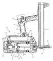
本発明に係るガスネイラAは、図1、2に図示されるように、駆動機構部a、ガス燃料カートリッジ2、過給装置3等を収納する釘打機本体1と、釘打機本体1と一体形成のグリップ4と、釘打機本体1の図示下部から突出するように設けられたマガジン部5を備えるノーズ部6等を備えている。なお、本発明の実施形態においては釘打ちについての説明がなされるが、釘打ちに限定されるものではなく、打ち込みネジ等の他のファスナの打ち込みにも適用可能である。 As shown in FIGS. 1 and 2, the gas nailer A according to the present invention includes a nail driver
そして、釘打機本体1内に収納される駆動機構部aは、打撃シリンダ7と、打撃シリンダ7上部の燃焼室8と、打撃シリンダ7内で往復摺動する打撃ピストン10と、一端基部(図示上端)が打撃ピストン10に固定された釘打ちドライバ11と、燃焼室8内に点火部を臨ませて燃焼室8の上部壁に装着された点火プラグ(図示せず)、供給されたガス燃料と空気を混合させる攪拌機12等からなり、さらに、駆動機構部aの始動のための初動を行うコンタクトアーム13等を備えている。以下に各構造部の概要について説明する。 And the drive mechanism part a accommodated in the nail driver
・打撃シリンダ
打撃シリンダ7は、釘打機本体1内の略中央部に配置され、図示上下方向に延長する所定径で所定肉厚の円筒からなる部材であり、打撃シリンダ7内には釘打ちドライバ11が一体的に固定された打撃ピストン10が往復摺動可能に嵌合されており、また、釘打ち作動に供された打撃ピストン10の下死点位置で開口して膨張した燃焼ガスを外部に排出する排気口14が打撃シリンダ7の下方側部に設けられている。Strike cylinder The
図3(a)も併せ参照して、円筒からなる打撃シリンダ7の図示上部には、該上部の外周に打撃ピストン10をその上死点において保持する部材である後述の係止装置15の下方延長部16が実質固定状態で密接嵌合され、さらに、該係止装置15の下方延長部16の外周に燃焼室8の環状周囲壁下部が摺動可能に密接接合し、これにより、燃焼室8の環状周囲壁は、打撃シリンダ7上部の外周に対して前記係止装置15を介して間接的に密接関係をもって上下方向で相対移動するようになされている。 Referring also to FIG. 3 (a), the upper portion of the cylindrical hitting
・打撃ピストン
打撃シリンダ7内で往復摺動可能とされた打撃ピストン10は、図に図示されるように大径ピストン部10aと、大径ピストン部10aの上部中央から突出する縮径された小径ピストン部10bを備えており、縮径された小径ピストン部10bの外周が前記係止装置15の本体部内周に所定の押圧荷重下で係止され、これにより打撃ピストン10は燃焼室8内における過給時の圧力上昇の下で打撃シリンダ7の上部に対して移動しないように始動初期の所定位置、つまり上死点に保持されている。Stroke piston The
打撃ピストン10は釘打ちのための作動に際して、打撃シリンダ7の上部に位置する待機状態である始動初期の所定位置を上死点とし、バンパ17への当接部を下死点として上下両死点間で往復移動し、その下方への移動において釘打ち作動を行い、打撃ピストン10の下方移動に伴うドライバ11により、マガジン部5からノーズ部6の射出口18内に供給された釘を打撃して釘打ちを行う。 When the
・燃焼室
燃焼室8は環状壁8aと上部壁8bからなり、図3(a)に図示されるように、環状壁8a下部の内周は係止装置15を介して打撃シリンダ7の上部外周に密接しかつ摺動可能に接合されており、また環状壁8aの上部は燃焼室8の固定壁である上部壁8bの外周にシール部19を介して密接しかつ摺動可能に接合されている。Combustion chamber The
そして、コンタクトアーム13の上下作動に連動して環状壁8aが上下動して、コンタクトアーム13の上方移動に伴う環状壁8aの上方移動で前記上部壁8bの外周との間のシール部19を閉鎖して燃焼室8を密閉し(図2の図示右側の環状壁8a上部参照)、下方移動に伴う環状壁8aの下方移動で該シール部19を開放して燃焼室8を大気に対して開放する(図2の図示左側の環状壁8a上部参照)ようになされており、密閉状態において後述のガス燃料カートリッジ2からガス燃料が供給され、過給装置3から圧縮空気が供給される。また上部壁8bには図示されない既述の点火プラグと攪拌機12が取り付けられている。 Then, the
・コンタクトアーム
コンタクトアーム13は、図においてもその全体図が明確に示されるところでないが、連接板21を介して上方のリンク部20に連結され、上記リンク部20はその一方のみが部分的に図示されており、その上端20aは燃焼室8の環状壁8a下部の下端に接続されている。The
そして、連接板21が打撃シリンダ7下部端面直下の空間内において円錐コイルバネ22により下方付勢されて、釘打ち作業に供されない待機状態においては、コンタクトアーム13の下端はノーズ部6の先端から突出する下方位置に保持され、釘打ち作業においては、図示されない被打込み材に押し付けられてノーズ部6の先端から突出しない位置に押し込まれる。 In the standby state in which the connecting
コンタクトアーム13の下端部の押し込み作動は、実質的にガスネイラAの釘打ち作業における駆動の初動操作であり、環状壁8aの上方移動により燃焼室8内を密封し、ロックアウトバー32によるトリガ28のロックを解除し、攪拌機12の図示されない駆動スイッチをオンし、アクチュエータ23を作動しガス燃料カートリッジ2を押してガス噴射口24を開口作動し、過給装置3の図示されない駆動スイッチをオンする。 The pushing operation of the lower end portion of the
また、コンタクトアーム13の下端部の下方位置への戻り作動は、コンタクトアーム13の押し込み作動の解除に伴うバネ22による戻し作動であり、この戻し作動により上述の各作動部の作動を初期状態へと復帰させる。 The return operation to the lower position of the lower end portion of the
・釘打ち出し部
ノーズ部6は、図1および図2に図示されるように、ドライバ11の摺動を案内するとともに、マガジン部5から送り出された釘を受け入れて打ち出す射出口18を有している。As shown in FIGS. 1 and 2, the
・ガス燃料カートリッジと過給装置
そして、図2から理解できるように、釘打機本体1内の打撃シリンダ7の図示右側部と燃焼室8の図示右側部の外側で上下に延びる長い側部空間内には、ガス燃料カートリッジ2が縦置きで配設されており、アクチュエータ23の作動による該カートリッジ2の燃料噴出口24の開口作動でガス燃料は燃焼室8の上部壁8bに形成された燃料供給路L1を経て燃焼室8内に供給される。Gas fuel cartridge and supercharging device And, as can be understood from FIG. 2, a long side space that extends vertically on the right side of the
また、釘打機本体1の図示上部、つまり燃焼室8の上部壁8bを覆う釘打機本体1の上部には過給装置3が設けられ、過給のための圧縮空気が燃焼室8に供給される。過給装置3は、周知の往復動型の圧縮空気ポンプ25と、圧縮空気ポンプ25を駆動する電動モータ26からなり、電動モータ26の駆動により、明確には図示されないモータ軸のギヤから減速歯車機構とクランク機構を介してピストン27を往復駆動することで所定圧の圧縮空気を燃焼室8内に過給のために供給するようになされている。過給のための燃焼室8内への圧縮空気の供給は、既述の燃焼室8上部壁8bに形成された圧縮空気供給路L2を経てなされる。 Further, a
・トリガスイッチ
駆動機構部a等を収納する釘打機本体1と一体形成のグリップ4には、トリガ28が設けられ、トリガ28の操作に伴うトリガ28スイッチ30のオン、オフ作動で図示されない点火プラグの点火制御を行うイグナイタ31が装備され、またイグナイタ31は攪拌機12のモータ12aと過給装置3のモータ26への電流の供給制御を行う。イグナイタ31はグリップ4の突出端部に収納されたバッテリBに電気的に接続されている。-Trigger
ガスネイラAは概ね上述の構造を備えるものである。なお、ガスネイラAの作動については、後述の実施形態のガスネイラAにおける作動説明と併せて後に説明される。 The gas nailer A generally has the above-described structure. The operation of the gas nailer A will be described later together with the operation description of the gas nailer A of the embodiment described later.
ところで、既に述べたところであるが、過給時の燃焼室8内における圧力上昇は打撃ピストン10の下方への移動を誘引するが、打撃ピストン10の下方移動は燃焼室8内の圧力上昇を妨げ、過給による出力増大の効果を減失させる。ガスネイラAは前記弊害の回避策として所定位置における打撃ピストン10保持のための係止装置15を備えており、概要については既に一部説明済みであるが、ここで、さらにその構造の詳細について説明を加えておく。 By the way, as already described, the pressure increase in the
既述のように、また、図2および図3等に図示されるように、打撃ピストン10は、実質的に大径ピストン部10aと小径ピストン部10bとからなる。そして、小径ピストン部10bの外周は燃焼室8の環状壁8a下部の内壁相当位置まで拡がる環状幅を有する環状の係止装置15により囲われ、結局、打撃ピストン10の受ける燃焼室8内の圧力は、該燃焼室8内に露出する受圧面積の小さな小径ピストン部10bの頭部(図2参照)で受けるようになされており、小径ピストン部10bの外周のやや上方部が係止装置15の後述の押圧手段41で所定の係止荷重下で係止され、これにより打撃ピストン10が燃焼室8内の圧力が所定圧内であれば打撃シリンダ7の上部の所定位置、つまり打撃ピストン10の移動の初期位置である上死点から移動しないように保持されている。 As described above and as illustrated in FIGS. 2 and 3 and the like, the
すなわち、少なくとも過給時の圧縮空気導入による燃焼室8内の圧力上昇、たとえば、本実施形態においては、過給が行われないガス燃料供給時の燃焼室8内の過給による圧力上昇、大気圧+0.5〜1kgf/cm2程度上昇する圧力に対して打撃ピストン10が前記所定位置で保持されるための係止荷重が打撃ピストン10に付与されている。(なお、過給による打撃ピストン10位置は、より正確には、過給圧により僅かながら押し下げられ、打撃ピストン10の所定位置である初期位置(図3(a)参照)から、過給後の打撃ピストン10の位置(図3(b)参照)に変化する(図3(b)のΔd参照)。That is, at least the pressure increase in the
係止装置15は環状で、小径ピストン部10bの上方の外周を押圧係止する押圧手段41を備え、シール部材34を介して小径ピストン部10bの外周に密封状態で摺動嵌合するとともに、燃焼室8の環状壁8a下部の内周にシール部材34を介して密封状態で摺動嵌合する本体部33と、本体部33の外周から下方に延びてかつ打撃シリンダ7上部の外周と燃焼室8の環状壁8a下部の内周間で延長する環状延長部33aとからなる。 The locking
そして、係止装置15は、前記環状延長部33aの内周が打撃シリンダ7上部の外周に実質固定状態で嵌合され、該嵌合状態において環状延長部33bの下端が打撃シリンダ7上部の外周の環状段部37に当接し、また、本体部33の下部38が打撃シリンダ7の上部端7aに当接するようになされ、これにより打撃シリンダ7上部に固定状態で嵌合保持されている。 The locking
係止装置15の押圧手段41は、環状の係止装置15の本体部33外周から内周に向って放射状に貫通する複数の、例えば4本の周方向で等間隔の孔40内に挿入されたバネ付勢の球状体からなり、該球状体41が内方に向って、つまり打撃ピストン10の中心部に向ってバネ42で付勢されて所定の押圧による係止荷重を小径ピストン部10bの外周に与えている。押圧手段41の押圧による係止荷重はネジ39のネジ込み調整により調節できる。 The pressing means 41 of the
一方、小径ピストン部10bの外周には前記押圧手段41の係止部である環状凹溝46が形成され、打撃ピストン10の下方への移動に対する係止保持の確実性が高められている。 On the other hand, on the outer periphery of the small-
そして、釘打ち込み時に、小径ピストン部10bの上面(図2参照)の受圧部が受ける燃焼室8内の圧力による打撃ピストン10の下方への移動力が係止装置15の係止荷重による打撃ピストン10の保持力を超えると、たとえば、燃焼時における燃焼ガスの膨張による燃焼室8内の圧力上昇時には、図3(c)に図示されるように、小径ピストン部10b外周の環状凹溝46に嵌り込む押圧手段41がバネ42の付勢力に抗して外方に押し戻されて係止装置15による打撃ピストン10の係止解除がなされ、打撃ピストン10は下方へ移動する。 When the nail is driven, the downward moving force of the
以後、小径ピストン部10bと大径ピストン部10aの双方の受圧部が受ける大きな燃焼ガスの膨張圧力による押し下げ力で打撃ピストン10は下方へ移動する。したがって、ドライバ11による釘打ちは何らの支障もなく行われる。 Thereafter, the
釘打ち終了後の打撃ピストン10の上方への戻り移動は、打撃シリンダ7内で膨張した燃焼ガスが排気口14からの外部へ排出した後の打撃シリンダ7内におけるガス冷却による体積の減少に基づく負圧の発生によるが、負圧により上方に戻される打撃ピストン10の小径ピストン部10b外周先端の大径部10aが、係止装置15の内周から突出する押圧手段41をバネ42の付勢力に抗して押し戻しつつ上方へ通過することでなされ、これにより打撃ピストン10は所定の初期位置に、つまり上死点に位置付けされる。この作用状態は図3(d)に図示されている。 The upward movement of the
本実施形態1においては打撃ピストン10の保持のための係止装置15による係止荷重が、実質的な打撃ピストン10の受圧面積の縮小化に伴い小さく設定されているので、上述の打撃シリンダ7内の負圧が、たとえば、−0.2〜−0.3kgf/cm2程度の負圧発生であっても、打撃ピストン10の上述の上方への戻り移動は十分に達成できる。In the first embodiment, the locking load by the locking
・ガスネイラの作動
上記実施形態におけるガスネイラAの打撃ピストン保持機構は上述のとおりであり、釘打ち作業のための作動は以下のような手順と作用によりなされる。次に、主に図2および図3により実施形態1について説明する。-Operation of the gas nailer The striking piston holding mechanism of the gas nailer A in the above embodiment is as described above, and the operation for nailing operation is performed by the following procedure and action. Next,
まず、ガスネイラAのコンタクトアーム13先端が被打込み材に押し付けられ、相対的にコンタクトアーム13はバネ22の付勢力に抗して図示上方に押し込められる。 First, the tip of the
コンタクトアーム13のバネ22に抗して上方移動すると、リンク部20を介して燃焼室8の環状壁8aを上方へ動かし開放状態である燃焼室8を閉鎖密封状態とし、また、僅かな時間差をもってガス燃料カートリッジ2のアクチュエータ23を押上げ作動し、ロックアウトバー32を作動してトリガ28のカム部材29の係合を解除し、さらに作動部材の押し上げ作動で攪拌機12駆動用モータの図示されないスイッチをオンし、また過給装置3の駆動用モータの図示されないスイッチをオンする。 When the
コンタクトアーム13の上述のガスネイラA始動のための初動により、ガス燃料カートリッジ2の燃料噴射開口24が開口操作され、一発の釘打ちのためのガス燃料が明確には図示されないメータリングバルブで計量されて燃焼室8上部壁8bに形成の燃料供給路L1を経て燃焼室8内に供給され、時を同じくして攪拌機12が回転駆動され、過給装置3のポンプ駆動による過給のための圧縮空気が前記上部壁8bに形成の圧縮空気供給路L2を経て燃焼室8内に供給され、空気とガス燃料が均一になるように前記攪拌機12により混合撹拌される。 By the initial movement of the
上述の過程において打撃シリンダ7内の実施形態1ないし3における打撃ピストン10は、過給による燃焼室8内の圧力上昇にも拘わらず、既述の実施形態1ないし3の係合装置の使用によりそれぞれ所定の係止荷重で保持され、殆ど動くことなく所定位置、すなわち、初期位置である上死点に保持される。 In the above-described process, the
次いで、トリガ28が手動により押し込み操作され、トリガ28スイッチがオンされてイグナイタにより図示されない点火プラグが点火され、燃焼室8内の混合燃料が燃焼する。 Next, the
混合燃料の燃焼による燃焼圧力は、打撃ピストン10頭部に作用して打撃ピストン10を係止装置15による係止から解放して下方へ移動させる。打撃ピストン10の下方への移動は、該打撃ピストン10に一体固定のドライバ11の先端をノーズ部6内の射出口18内で下方移動させる。ドライバ11の先端の前記射出口18内における下方移動は、マガジン部5から該射出口18内に送り込まれた釘の頭部を該ドライバ11で撃打して、該釘を釘打ち作業部の所定位置に打ち込む。 The combustion pressure due to the combustion of the mixed fuel acts on the head of the
そして、打撃ピストン10は下死点まで下方移動して、ドライバ11の先端は僅かにノーズ部6の先端から突出して完全に釘の頭部を打ち出し、確実な釘打ちを行う。打撃ピストン10が下死点まで下方移動すると、打撃シリンダ7の下方側部の排気口14から膨張しきった排気ガスが排出される。 Then, the
打撃シリンダ7内からの排気ガスの外部への排出は、打撃シリンダ7内のガスを冷却させてその体積を減少させ、打撃シリンダ7内の負圧の発生を促す。打撃シリンダ7内における負圧の発生は打撃ピストン10を上方へ戻すように移動させる。 Exhaust of the exhaust gas from the inside of the
上述の作動と相前後して、トリガ28の操作が解放されると、トリガ28によってカムが図示右回りして初期位置に戻り、ロックアウトバー32は下方移動可能となり、燃焼室が開放される。つまり連接板21が下方移動可能となる。 Before and after the above operation, when the operation of the
連接板21の下方への移動は、燃焼室8の環状壁8aを下方へ動かし、環状壁8aと燃焼室8の上部壁8bの外周との摺接シール部19を開放して、開放された該シール部19からは燃焼室8内へ空気が流入する。また、時を同じくしてガス燃料カートリッジ2のアクチュエータ23や攪拌機12の図示されないモータ駆動スイッチ、過給装置3のモータ駆動スイッチはオフされ、操作解放状態のトリガ28はロックアウトバー32の下方移動によりロックされ、ガスネイラAの誤操作を防止する。 The downward movement of the connecting
ところで、打撃シリンダ7の上方への打撃ピストン10の戻りのための移動に関しては、戻り移動の円滑性の確保の視点から、上死点近傍の係止装置15の係止荷重の影響に配慮されねばならず、このために、実施形態1における上述の係止装置15の使用においては、係止装置15の押圧による係止力が弱く設定され、これにより打撃ピストン10の戻り移動で係止装置15の係止荷重による係止力を凌駕して、すなわち、比較的弱いバネ押圧の球状体41を打撃シリンダ7内の負圧による打撃ピストン10の戻り移動で押し戻して、打撃ピストン10は上死点である所定の初期位置に支障なく戻され位置付けされるようになされている。 By the way, regarding the movement for returning the
・他の実施形態
次に、ガスネイラAの他の実施形態について説明する。これら実施形態のガスネイラAは実質的に実施形態1のガスネイラAにおいてその打撃ピストン保持構造のみに変更が加えられたものであり、他の構造部については何ら変更が加えられたものでなく、実施形態の説明は、既述の実施形態1と共通する部材については同一符号を用いてなされる。Other Embodiments Next, other embodiments of the gas nailer A will be described. The gas nailer A of these embodiments is substantially the same as that of the gas nailer A of the first embodiment, except that the striking piston holding structure is changed, and the other structural portions are not changed at all. The description of the form is made using the same reference numerals for members that are the same as those in the first embodiment.
・実施形態2
実施形態2における打撃ピストン10は、図4、5に図示されるように、打撃ピストン10の外周が打撃シリンダ7の内壁にシールリング43を介して摺動するようになされ、打撃ピストン10の上部周辺が環状の突出部44とされた構造を備え、打撃ピストン10の上部周辺の環状の突出部44は打撃ピストン10が上死点に位置するとき打撃シリンダ7の上部から所定高さで突出している。
As shown in FIGS. 4 and 5, the
打撃ピストン10の上部周辺の環状突出部44の外周には係止装置15による係止に供されるための環状凹溝46が形成され、この環状凹溝46に係止装置15の係止素子である球状体41が係止して打撃ピストン10はその係止力の所定の荷重下で所定位置に保持されている。 An
すなわち、燃焼室8内の所定内の圧力に対して打撃ピストン10が移動することなく保持され、少なくとも過給時の圧縮空気の導入による燃焼室8内の圧力上昇、たとえば、大気圧からさらに+0.5kgf/cm2程度上昇する圧力に対して打撃ピストン10が所定位置に移動することなく保持されるようになされている。That is, the
係止装置15は、環状の固定部47と可動部48からなり、固定部47は、径の異なる内周を備えており、その図示下方のやや径大とされた内周部分が打撃シリンダ7上部の外周に実質固定状態で嵌合され、中央のやや径小とされた内周部分が打撃ピストン10の上部外周に摺動可能に嵌合され、これにより打撃シリンダ7上部外周に固定状態とされた固定部47に対して打撃ピストン10がその上部外周を介して摺動可能とされる部材であり、かつ球状体41を保持する開孔51を備えている。 The locking
また、可動部48は、固定部47の外周にシール部材52を介して摺動嵌合する内周を備えると共に固定部47の上端の外向き鍔部53に上端が支持されるバネ54のバネ力と、可動部48の上端面に加えられる燃焼室8内の圧力とにより下方へ付勢され、打撃ピストン10の打ち込み方向と平行に摺動可能に設けられている。さらに、可動部48は、このための固定部47の球状体58と協働する係止手段である傾斜面55を有する係止溝部56をその内周に備えている。 The
係止装置15による打撃ピストン10の係止は、可動部48内周の傾斜面55を有する係止溝部56が、固定部47の球状体41に対向して位置付けられ、可動部48の摺動により、つまり可動部48が図5(a)(b)に図示される如くバネ54のバネ力と上端面からの受圧とで下方位置に移動することで、その係止溝部56の傾斜面55が球状体41を図示右方側へと押圧し、該球状体41が打撃ピストン10の外周の環状凹溝55に強く押し付けられて打撃ピストン10を係止することでなされる。 When the
係止された打撃ピストン10は所定の係止荷重による保持力、つまり、燃焼室8内の所定内の圧力に対して移動しないように打撃シリンダ7上部に対して係止保持され、少なくとも上述の燃焼室8内への過給のための圧縮空気導入による燃焼室8内の圧力の上昇に対して打撃ピストン10を所定位置に、すなわち初期位置である上死点に移動することなく係止保持されるようになされている。 The
そして、燃焼室8内の圧力が上述の所定内圧力を超えると、燃焼室8内の圧力を上面受圧部で受ける打撃ピストン10の下方への移動力が係止装置15による所定の係止荷重による打撃ピストン10の保持力を上回り、たとえば、図5(c)に図示されるように、燃焼時の燃焼ガスの膨張による燃焼室8内の圧力上昇においては、上述の係止装置15による打撃ピストン10の保持力は打撃ピストン10の下方への移動力により凌駕されて解除される。 When the pressure in the
つまり、打撃ピストン10の頭部の受圧面で受ける圧力による打撃ピストン10の下方への移動力で、打撃ピストン10の外周の環状凹溝46に嵌り込む球状体41が押し戻され、球状体41の傾斜面55への押圧力により、可動部48を、バネ54のバネ力と可動部48上端面に対する過給圧による受圧に抗して、同図(b)から同図(c)に示すように、上方に移動させるように作用し、球状体41と傾斜面55との当接位置がずれて係止が外れる。これにより打撃ピストン10は係止装置15による係止保持力から解放されて下方へ移動し、ドライバ11による釘打ち作業が何ら支障なく行われる。 That is, the
ところで、釘打ちのための作動終了に伴う打撃ピストン10の上方への戻り移動は、打撃シリンダ7内の膨張した燃焼ガスの外部への排出後のガス冷却による体積の減少に基づく打撃シリンダ7内における負圧発生によるものであるが、この打撃ピストン10を戻す負圧により係止装置15はその係止が解除された状態として保持される。 By the way, the upward movement of the
すなわち、図5(d)に図示されるように、打撃シリンダ7内の上述の負圧、たとえば、−0.2〜−0.3kgf/cm2程度の負圧の発生により、係止装置15の可動部48は上方位置に移動しているから、打撃ピストン10は確実に所定の上方位置にリターンする。That is, as shown in FIG. 5D, the locking
このように、可動部48をバネ力だけでなく過給圧を利用することで下方に付勢する構成なので、バネ54のバネ力を低く設定することができる。また、過給圧を利用することにより、燃焼室8が負圧になるときは、負圧分だけバネ54の力がさらに弱められるので、打撃ピストン10のリターンに対する抵抗は小さくなり、確実にリターンできる。 Thus, since the
・実施形態3
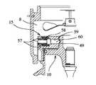
図6には打撃ピストン保持機構の実施形態3が示され、既述の実施形態1の打撃ピストン10保持構造の変形例としてソレノイド57による打撃ピストン10の係止と係止解除が行われる係止装置15が提供される。
FIG. 6 shows a third embodiment of the striking piston holding mechanism. As a modification of the
この係止装置15は、バネ58で押圧される先端が球状の押圧手段60をソレノイド57により孔部59に沿って摺動可能として、打撃ピストン10保持のための打撃ピストン10係止時には、ソレノイド57への通電の停止により該ソレノイド57を消磁して、押圧手段60の先端をバネの付勢力で打撃ピストン10の係止凹溝49に押し付ける。 The locking
また、打撃ピストン10の係止解除時には、ソレノイド57への通電により該ソレノイド57を励磁して押圧手段65をバネ58の付勢力に抗して引き戻し、押圧手段60による係止を解除するようになされている。 Further, when the
・実施形態2、3のガスネイラの作動
実施形態2及び実施形態3の場合も同様に作動するが、実施形態2における係止装置15の使用においては、係止装置15の摺動ロック部材は打撃シリンダ7と燃焼室8内の負圧により上方へ移動してその傾斜面55を球状体から離して球状体を自由状態にして係止解除状態とされるので、打撃シリンダ7と燃焼室8内の負圧による打撃ピストン10の戻り移動は該係止装置15の影響を直接受けることなく行われ、打撃ピストン10は上死点である所定の初期位置に支障なく戻され位置付けされる。The operation of the gas nailer according to the second and third embodiments operates similarly in the second and third embodiments, but in the use of the
また、実施形態3における係止装置15の使用においては、ソレノイド57の励磁によるバネの付勢力に抗した作動ピンの吸引による引き戻しで打撃ピストン10係止が解除されるから、打撃ピストン10の戻り移動は円滑に行われ、打撃ピストン10は所定の初期位置に支障なく戻され位置付けされる。 Further, in the use of the
・本発明の実施形態における効果
本発明の実施形態においては、上述の構成を備えることで、以下のような効果を奏する。-Effect in embodiment of this invention In embodiment of this invention, there exist the following effects by providing the above-mentioned structure.
実施形態1においては、打撃ピストン10が大径ピストン部10aと小径ピストン部10bからなり、小径ピストン部10bがその頭部で燃焼室8内の圧力を受けるようになされているので、打撃ピストン10の受圧面積の縮小が図られ、過給による燃焼室8内の圧力上昇による打撃ピストン10への影響が小さく抑えられており、打撃ピストン10の下方への移動は比較的小さな係止装置15の係止荷重で阻止することができるので、係止装置15の小型・簡素化が可能であり、コストの低減を図ることができる。また、釘打ち作業終了後の負圧による打撃ピストン10の戻り移動も係止荷重が小さいので支障なくなされる。 In the first embodiment, the
一方、燃焼時の打撃ピストン10の下方移動に際して、燃焼圧力は小径ピストン部10bと大径ピストン部10aの双方の頭部で受圧されるので釘打ち込み力の強化が図られ、過給による出力増加のもとに釘打ち作業の作業性の一層の向上が図られる。 On the other hand, when the
実施形態2においては、係止装置15は傾斜面を有する可動部48を具備し、バネ54の付勢力が可動部48を図示下方に押圧し、その傾斜面55で球状体45を打撃ピストン10外周の環状凹溝46に向けて押し付けるので打撃ピストン10の係止は強固になされ、過給時における係止装置15による打撃ピストン10の確実な保持が達成される。 In the second embodiment, the locking
また、傾斜面55を有する可動部48は、打撃ピストン10の戻り時の打撃シリンダ7内における負圧の発生で固定部47に対して相対移動し、球状体41を自由にして係止装置15による打撃ピストン10の係止を解除するから、打撃ピストン10の戻り時における上方移動は支障なく円滑に行われる。したがって、結果として過給による出力増大のもとにガスネイラAによる釘打ち作業の作業性の向上が図られる。 Further, the
さらに、実施形態3のように実施形態1における係止装置15を変形して押圧手段60をソレノイド57で操作可能とすることで、係止装置15による選択的な打撃ピストン10の係止及び係止解除が可能となる。したがって、ソレノイド57への通電の停止による該ソレノイド57の消磁で係止装置15のバネ力利用の係止がなされて、過給時における確実な打撃ピストン10の所定位置における保持が達成され、また釘打ち作業終了後の負圧による打撃ピストン10の戻り移動は、ソレノイド57への通電による該ソレノイド57の励磁で係止装置15のバネ力利用の係止が解除されるので円滑になされる。 Further, as in the third embodiment, the locking
A ガスネイラ
2 ガス燃料カートリッジ
3 過給装置
7 打撃シリンダ
8 燃焼室
10 打撃ピストン
13 コンタクトアーム
15 係止装置A
Claims (4)
Translated fromJapanese前記過給装置による過給時の圧縮空気の供給に伴う前記燃焼室内の圧力上昇によっては該打撃ピストンを移動させないようにするために、前記打撃シリンダには前記打撃ピストンに係止する係止装置を設けた
ことを特徴とするガスネイラにおける打撃ピストン保持機構。A striking cylinder, a striking piston that reciprocates in the striking cylinder, a combustion chamber connected to the top of the striking cylinder, a gas fuel cartridge that supplies gas fuel into the combustion chamber, and a compression for supercharging in the combustion chamber A supercharging device for supplying air, and operating the striking piston in the striking cylinder by the combustion pressure of the gas fuel and air mixture in the combustion chamber, and driving the fastener by the driver through the operation of the striking piston. In the striking piston holding mechanism in the gas nailer,
A locking device that locks the striking cylinder to the striking piston so as not to move the striking piston due to an increase in pressure in the combustion chamber accompanying the supply of compressed air during supercharging by the supercharging device A striking piston holding mechanism in a gas nailer, characterized in that.
2. The striking piston holding mechanism in a gas nailer according to claim 1, wherein the locking device can be engaged and disengaged in connection with excitation and demagnetization of a solenoid.
Priority Applications (10)
| Application Number | Priority Date | Filing Date | Title |
|---|---|---|---|
| JP2006047258AJP2007222989A (en) | 2006-02-23 | 2006-02-23 | Drive piston holding structure in gas nailer |
| TW096105679ATW200734137A (en) | 2006-02-23 | 2007-02-15 | Hammering piston holding structure in gas nailer |
| PCT/JP2007/053107WO2007099819A1 (en) | 2006-02-23 | 2007-02-20 | Hammering piston holding structure in gas nailer |
| EP07714607AEP1987924B1 (en) | 2006-02-23 | 2007-02-20 | Gas nailer comprising a hammering piston holding structure |
| US12/280,409US20080314952A1 (en) | 2006-02-23 | 2007-02-20 | Driving Piston Maintaining Structure in Gas Nailer |
| EP11009535AEP2433753A1 (en) | 2006-02-23 | 2007-02-20 | Driving piston maintaining structure in gas nailer |
| AU2007219847AAU2007219847A1 (en) | 2006-02-23 | 2007-02-20 | Hammering piston holding structure in gas nailer |
| KR1020087020588AKR20080098501A (en) | 2006-02-23 | 2007-02-20 | Strike piston holding structure in gas nailer |
| AT07714607TATE542640T1 (en) | 2006-02-23 | 2007-02-20 | GAS POWERED NAIL GUN WITH HAMMER PISTON HOLDING STRUCTURE |
| CN200780006570XACN101389449B (en) | 2006-02-23 | 2007-02-20 | Hammering piston holding structure in gas nailer |
Applications Claiming Priority (1)
| Application Number | Priority Date | Filing Date | Title |
|---|---|---|---|
| JP2006047258AJP2007222989A (en) | 2006-02-23 | 2006-02-23 | Drive piston holding structure in gas nailer |
Publications (1)
| Publication Number | Publication Date |
|---|---|
| JP2007222989Atrue JP2007222989A (en) | 2007-09-06 |
Family
ID=38458931
Family Applications (1)
| Application Number | Title | Priority Date | Filing Date |
|---|---|---|---|
| JP2006047258APendingJP2007222989A (en) | 2006-02-23 | 2006-02-23 | Drive piston holding structure in gas nailer |
Country Status (9)
| Country | Link |
|---|---|
| US (1) | US20080314952A1 (en) |
| EP (2) | EP1987924B1 (en) |
| JP (1) | JP2007222989A (en) |
| KR (1) | KR20080098501A (en) |
| CN (1) | CN101389449B (en) |
| AT (1) | ATE542640T1 (en) |
| AU (1) | AU2007219847A1 (en) |
| TW (1) | TW200734137A (en) |
| WO (1) | WO2007099819A1 (en) |
Cited By (8)
| Publication number | Priority date | Publication date | Assignee | Title |
|---|---|---|---|---|
| WO2008114620A1 (en) | 2007-03-19 | 2008-09-25 | Asahi Glass Company, Limited | Process for producing electroconductor |
| WO2009044619A1 (en)* | 2007-10-04 | 2009-04-09 | Makita Corporation | Drive tool |
| JP2011093087A (en)* | 2009-09-30 | 2011-05-12 | Hitachi Koki Co Ltd | Driving machine |
| JP2019136820A (en)* | 2018-02-09 | 2019-08-22 | マックス株式会社 | Driving tool |
| JP2019136819A (en)* | 2018-02-09 | 2019-08-22 | マックス株式会社 | Driving tool |
| JP2019188535A (en)* | 2018-04-25 | 2019-10-31 | マックス株式会社 | Driving tool |
| WO2020008768A1 (en)* | 2018-07-06 | 2020-01-09 | 工機ホールディングス株式会社 | Driving machine |
| JP2022167029A (en)* | 2021-04-22 | 2022-11-04 | アビエンジニアリング株式会社 | Anchor installation method |
Families Citing this family (20)
| Publication number | Priority date | Publication date | Assignee | Title |
|---|---|---|---|---|
| JP4788228B2 (en)* | 2005-08-08 | 2011-10-05 | マックス株式会社 | Combustion chamber holding mechanism in gas combustion type driving tool |
| US8550321B2 (en) | 2008-05-21 | 2013-10-08 | Poly Systems Pty Ltd | Tool for driving fasteners |
| FR2972666B1 (en)* | 2011-03-16 | 2014-04-25 | Prospection & Inventions | GAS SEALING TOOL WITH LIMITED FUEL LOSS |
| CN104144770A (en)* | 2011-10-13 | 2014-11-12 | 多系统私人有限公司 | Hand held power tool for driving fasteners |
| FR2988634B1 (en)* | 2012-04-03 | 2014-03-21 | Illinois Tool Works | REMOVABLE ADAPTER FOR ADMISSION AND MIXING OF AIR AND FUEL FOR A COMBUSTION TOOL |
| US9676090B2 (en) | 2012-06-21 | 2017-06-13 | Illinois Tool Works Inc. | Fastener-driving tool with an electric power generator |
| US20130341057A1 (en)* | 2012-06-21 | 2013-12-26 | Illinois Tool Works Inc. | Fastener-driving tool with an electric power generator |
| CN105339137B (en)* | 2013-08-22 | 2017-09-29 | 创科电动工具科技有限公司 | Pneumatic fastener driver |
| EP3031581A1 (en)* | 2014-12-12 | 2016-06-15 | HILTI Aktiengesellschaft | Setting device and method for operating same |
| EP3181295A1 (en)* | 2015-12-18 | 2017-06-21 | HILTI Aktiengesellschaft | Internal combustion operated driving tool |
| EP3184250A1 (en)* | 2015-12-22 | 2017-06-28 | HILTI Aktiengesellschaft | Internal combustion gas operated driving tool |
| CN108000440B (en)* | 2017-12-04 | 2024-05-31 | 北京大风时代科技有限责任公司 | Nailing device |
| DK3572189T3 (en) | 2018-01-19 | 2021-09-20 | Max Co Ltd | Recovery tool |
| US11279014B2 (en)* | 2018-01-19 | 2022-03-22 | Max Co., Ltd. | Gas combustion type driving tool |
| US20190224831A1 (en)* | 2018-01-19 | 2019-07-25 | Max Co., Ltd. | Driving tool |
| US11338422B2 (en) | 2018-01-19 | 2022-05-24 | Max Co., Ltd. | Driving tool |
| FR3086569B1 (en)* | 2018-10-01 | 2020-12-18 | Illinois Tool Works | GAS FIXING TOOL AND ITS OPERATING PROCEDURE |
| US11819989B2 (en) | 2020-07-07 | 2023-11-21 | Techtronic Cordless Gp | Powered fastener driver |
| CA3167425A1 (en) | 2021-07-16 | 2023-01-16 | Techtronic Cordless Gp | Powered fastener driver |
| EP4467292A1 (en) | 2023-05-22 | 2024-11-27 | Hilti Aktiengesellschaft | Handheld tool |
Citations (5)
| Publication number | Priority date | Publication date | Assignee | Title |
|---|---|---|---|---|
| JPH1044060A (en)* | 1996-05-03 | 1998-02-17 | Illinois Tool Works Inc <Itw> | Combustion power type drive tool for fastener |
| JP2004009186A (en)* | 2002-06-05 | 2004-01-15 | Max Co Ltd | Piston stop mechanism for compressed air driven nailing machine |
| US20040134961A1 (en)* | 2002-12-23 | 2004-07-15 | Iwan Wolf | Combustion-engined setting tool |
| US20050001002A1 (en)* | 2003-04-24 | 2005-01-06 | Ulrich Schiestl | Combustion-engined setting tool |
| WO2005063449A1 (en)* | 2003-12-30 | 2005-07-14 | Poly Systems Pty Ltd | Fastener driving tool |
Family Cites Families (35)
| Publication number | Priority date | Publication date | Assignee | Title |
|---|---|---|---|---|
| US2957176A (en)* | 1955-08-22 | 1960-10-25 | Olin Mathieson | Explosively actuated fastener driving tool with safety and cartridge extractor means |
| US3081741A (en)* | 1956-10-29 | 1963-03-19 | Modernair Corp | Pneumatic fastener driving machine |
| US2946313A (en)* | 1958-02-03 | 1960-07-26 | Powers Wire Products Company I | Fastener driving tool and release therefor |
| DE1225120B (en)* | 1961-03-15 | 1966-09-15 | Behrens Friedrich Joh | Compressed air device for driving fasteners, e.g. B. nails or U-shaped brackets |
| DE1277166B (en)* | 1963-04-27 | 1968-09-05 | Behrens Friedrich Joh | Device operated with compressed air for driving in nails, staples or the like. |
| NL6415071A (en)* | 1964-12-24 | 1966-06-27 | ||
| US3397620A (en)* | 1966-10-06 | 1968-08-20 | Milwaukee Cylinder Corp | Fluid actuator with annular piston locking means |
| US3811275A (en)* | 1969-04-02 | 1974-05-21 | A Mastrobuono | Rotary turbine engine |
| US3601300A (en)* | 1970-01-23 | 1971-08-24 | Edgar P Anstett | Pneumatically operated nailing machine |
| USRE28842E (en)* | 1971-07-06 | 1976-06-08 | Spraying Systems Co. | Unloader valve for spray guns |
| DE2339162C2 (en)* | 1973-08-02 | 1975-04-03 | Karl M. Reich, Maschinenfabrik Gmbh, 7440 Nuertingen | Locking device for pneumatic nailers to catch and hold the impact piston |
| DE2548014C2 (en)* | 1975-10-27 | 1984-01-12 | Hilti AG, 9494 Schaan | Powder-powered setting tool with power regulation |
| DE3019777A1 (en)* | 1980-05-23 | 1982-02-04 | Jayne Engineering, Inc., Northampton, Mass. | Impact tool with self-contained power supply - has piston supplied with fuel mixture for ignition by piezoelectric crystal operated sparking plug |
| DE3020286A1 (en)* | 1980-05-28 | 1981-12-03 | Hilti AG, 9494 Schaan | INTERNAL POWERED SETTING DEVICE |
| US4403722A (en)* | 1981-01-22 | 1983-09-13 | Signode Corporation | Combustion gas powered fastener driving tool |
| US4635536A (en)* | 1983-09-19 | 1987-01-13 | Miller Fluid Power Corporation | Cylinder locking apparatus |
| DE3611171A1 (en)* | 1986-01-20 | 1987-07-30 | Guenter Mehnert | DRIVE SYSTEM, ESPECIALLY FOR MOTOR VEHICLES |
| DE4032204C2 (en)* | 1990-10-11 | 1999-10-21 | Hilti Ag | Setting tool for fasteners |
| DE4032202C2 (en)* | 1990-10-11 | 1999-10-21 | Hilti Ag | Setting tool for fasteners |
| US5181450A (en)* | 1991-05-16 | 1993-01-26 | Umberto Monacelli | Pneumatic fastener driving apparatus with piston holding detent |
| US5191861A (en)* | 1991-07-12 | 1993-03-09 | Stanley-Bostitch, Inc. | Internal combustion actuated portable tool |
| US5263439A (en)* | 1992-11-13 | 1993-11-23 | Illinois Tool Works Inc. | Fuel system for combustion-powered, fastener-driving tool |
| FR2730443B1 (en)* | 1995-02-15 | 1997-04-11 | Spit Soc Prospect Inv Techn | COMPRESSED GAS PISTON SEALING APPARATUS |
| US5699948A (en)* | 1996-12-16 | 1997-12-23 | Lee; Cheng-Ho | Adjusting means for use in a staple gun |
| JP3405107B2 (en)* | 1997-01-31 | 2003-05-12 | マックス株式会社 | Pneumatic screw driving machine |
| DE19962696C1 (en)* | 1999-12-23 | 2001-06-07 | Hilti Ag | Power tool with an internal combustion power unit to drive mountings home has a brake system at the piston rod with an adjustable braking force to set the power transferred from the combustion chamber to the piston |
| DE10105882C2 (en)* | 2001-02-09 | 2002-12-05 | Hilti Ag | piston holder |
| EP1539424B1 (en)* | 2002-07-23 | 2007-05-23 | Oleg Ivanovich Grechishkin | Abrasive blasting device |
| DE10253670B4 (en)* | 2002-11-19 | 2021-05-06 | Hilti Aktiengesellschaft | Internal combustion-powered setting tool |
| DE10254965B4 (en)* | 2002-11-26 | 2021-05-06 | Hilti Aktiengesellschaft | Internal combustion-powered setting tool |
| DE10259777B4 (en)* | 2002-12-19 | 2016-06-30 | Hilti Aktiengesellschaft | Internal combustion engine, in particular setting device for fastening elements |
| DE10308359B4 (en)* | 2003-02-27 | 2020-12-10 | Hilti Aktiengesellschaft | Internal combustion-powered setting tool |
| TWI273955B (en)* | 2004-02-20 | 2007-02-21 | Black & Decker Inc | Dual mode pneumatic fastener actuation mechanism |
| JP4326002B2 (en) | 2004-07-05 | 2009-09-02 | 株式会社リコー | Powder adhesion force measuring method and apparatus, and powder friction force measuring method and apparatus |
| EP1640597B1 (en)* | 2004-09-22 | 2008-07-23 | Ford Global Technologies, LLC | Supercharged internal combustion engine and method for operating such an internal combustion engine |
- 2006
- 2006-02-23JPJP2006047258Apatent/JP2007222989A/enactivePending
- 2007
- 2007-02-15TWTW096105679Apatent/TW200734137A/enunknown
- 2007-02-20AUAU2007219847Apatent/AU2007219847A1/ennot_activeAbandoned
- 2007-02-20KRKR1020087020588Apatent/KR20080098501A/ennot_activeWithdrawn
- 2007-02-20EPEP07714607Apatent/EP1987924B1/ennot_activeNot-in-force
- 2007-02-20USUS12/280,409patent/US20080314952A1/ennot_activeAbandoned
- 2007-02-20EPEP11009535Apatent/EP2433753A1/ennot_activeWithdrawn
- 2007-02-20WOPCT/JP2007/053107patent/WO2007099819A1/enactiveApplication Filing
- 2007-02-20CNCN200780006570XApatent/CN101389449B/ennot_activeExpired - Fee Related
- 2007-02-20ATAT07714607Tpatent/ATE542640T1/enactive
Patent Citations (5)
| Publication number | Priority date | Publication date | Assignee | Title |
|---|---|---|---|---|
| JPH1044060A (en)* | 1996-05-03 | 1998-02-17 | Illinois Tool Works Inc <Itw> | Combustion power type drive tool for fastener |
| JP2004009186A (en)* | 2002-06-05 | 2004-01-15 | Max Co Ltd | Piston stop mechanism for compressed air driven nailing machine |
| US20040134961A1 (en)* | 2002-12-23 | 2004-07-15 | Iwan Wolf | Combustion-engined setting tool |
| US20050001002A1 (en)* | 2003-04-24 | 2005-01-06 | Ulrich Schiestl | Combustion-engined setting tool |
| WO2005063449A1 (en)* | 2003-12-30 | 2005-07-14 | Poly Systems Pty Ltd | Fastener driving tool |
Cited By (16)
| Publication number | Priority date | Publication date | Assignee | Title |
|---|---|---|---|---|
| WO2008114620A1 (en) | 2007-03-19 | 2008-09-25 | Asahi Glass Company, Limited | Process for producing electroconductor |
| WO2009044619A1 (en)* | 2007-10-04 | 2009-04-09 | Makita Corporation | Drive tool |
| JP2009090384A (en)* | 2007-10-04 | 2009-04-30 | Makita Corp | Driving tool |
| US8215528B2 (en) | 2007-10-04 | 2012-07-10 | Makita Corporation | Drive tool |
| JP2011093087A (en)* | 2009-09-30 | 2011-05-12 | Hitachi Koki Co Ltd | Driving machine |
| JP7091687B2 (en) | 2018-02-09 | 2022-06-28 | マックス株式会社 | Driving tool |
| JP2019136820A (en)* | 2018-02-09 | 2019-08-22 | マックス株式会社 | Driving tool |
| JP2019136819A (en)* | 2018-02-09 | 2019-08-22 | マックス株式会社 | Driving tool |
| JP7183543B2 (en) | 2018-02-09 | 2022-12-06 | マックス株式会社 | driving tool |
| JP2019188535A (en)* | 2018-04-25 | 2019-10-31 | マックス株式会社 | Driving tool |
| JP7047572B2 (en) | 2018-04-25 | 2022-04-05 | マックス株式会社 | Driving tool |
| WO2020008768A1 (en)* | 2018-07-06 | 2020-01-09 | 工機ホールディングス株式会社 | Driving machine |
| JP7115544B2 (en) | 2018-07-06 | 2022-08-09 | 工機ホールディングス株式会社 | hammer |
| JPWO2020008768A1 (en)* | 2018-07-06 | 2021-06-24 | 工機ホールディングス株式会社 | Driving machine |
| US11724375B2 (en) | 2018-07-06 | 2023-08-15 | Koki Holdings Co., Ltd. | Driving tool with switching mechanism |
| JP2022167029A (en)* | 2021-04-22 | 2022-11-04 | アビエンジニアリング株式会社 | Anchor installation method |
Also Published As
| Publication number | Publication date |
|---|---|
| EP1987924A1 (en) | 2008-11-05 |
| CN101389449B (en) | 2011-12-07 |
| AU2007219847A1 (en) | 2007-09-07 |
| US20080314952A1 (en) | 2008-12-25 |
| EP2433753A1 (en) | 2012-03-28 |
| KR20080098501A (en) | 2008-11-10 |
| ATE542640T1 (en) | 2012-02-15 |
| WO2007099819A1 (en) | 2007-09-07 |
| TW200734137A (en) | 2007-09-16 |
| CN101389449A (en) | 2009-03-18 |
| EP1987924B1 (en) | 2012-01-25 |
| EP1987924A4 (en) | 2010-09-15 |
Similar Documents
| Publication | Publication Date | Title |
|---|---|---|
| JP2007222989A (en) | Drive piston holding structure in gas nailer | |
| US12285850B2 (en) | Reversion trigger for combustion-powered fastener-driving tool | |
| JP4685212B2 (en) | Combustion power tool | |
| US8336749B2 (en) | Single switched dual firing condition combustion nailer | |
| US6889885B2 (en) | Combustion-powered nail gun | |
| JP4741518B2 (en) | Combustion chamber control for combustion powered fastener drive tools | |
| TWI419774B (en) | Gas burned into the tool | |
| CA2865996C (en) | Lockout for fastener-driving tool | |
| US20100176177A1 (en) | Gas combustion type striking tool | |
| US20060102111A1 (en) | Combustion-type power tool | |
| US20060186166A1 (en) | Combustion-type power tool | |
| JP2007245303A (en) | Driving machine | |
| JP2007237328A (en) | Combustion power tool | |
| JP2006315102A (en) | Gas combustion type driving tool | |
| JP2008073773A (en) | Gas combustion type nailing tool | |
| WO2006123692A1 (en) | Fuel gas type hammering tool | |
| US20200276692A1 (en) | Fuel-powered setting device and method for operating such a setting device | |
| JP5003259B2 (en) | Gas internal combustion nailer | |
| US7293541B2 (en) | Combustion-type power tool having ignition proof arrangement |
Legal Events
| Date | Code | Title | Description |
|---|---|---|---|
| A621 | Written request for application examination | Free format text:JAPANESE INTERMEDIATE CODE: A621 Effective date:20080926 | |
| A131 | Notification of reasons for refusal | Free format text:JAPANESE INTERMEDIATE CODE: A131 Effective date:20110823 | |
| A521 | Request for written amendment filed | Free format text:JAPANESE INTERMEDIATE CODE: A523 Effective date:20111024 | |
| A02 | Decision of refusal | Free format text:JAPANESE INTERMEDIATE CODE: A02 Effective date:20120703 |