JP2007219692A - Process abnormality analyzing device, process abnormality analyzing system and program - Google Patents
Process abnormality analyzing device, process abnormality analyzing system and programDownload PDFInfo
- Publication number
- JP2007219692A JP2007219692AJP2006037588AJP2006037588AJP2007219692AJP 2007219692 AJP2007219692 AJP 2007219692AJP 2006037588 AJP2006037588 AJP 2006037588AJP 2006037588 AJP2006037588 AJP 2006037588AJP 2007219692 AJP2007219692 AJP 2007219692A
- Authority
- JP
- Japan
- Prior art keywords
- abnormality
- data
- analysis
- manufacturing
- data storage
- Prior art date
- Legal status (The legal status is an assumption and is not a legal conclusion. Google has not performed a legal analysis and makes no representation as to the accuracy of the status listed.)
- Pending
Links
Images


Classifications
- G—PHYSICS
- G06—COMPUTING OR CALCULATING; COUNTING
- G06Q—INFORMATION AND COMMUNICATION TECHNOLOGY [ICT] SPECIALLY ADAPTED FOR ADMINISTRATIVE, COMMERCIAL, FINANCIAL, MANAGERIAL OR SUPERVISORY PURPOSES; SYSTEMS OR METHODS SPECIALLY ADAPTED FOR ADMINISTRATIVE, COMMERCIAL, FINANCIAL, MANAGERIAL OR SUPERVISORY PURPOSES, NOT OTHERWISE PROVIDED FOR
- G06Q10/00—Administration; Management
- G06Q10/06—Resources, workflows, human or project management; Enterprise or organisation planning; Enterprise or organisation modelling
- G—PHYSICS
- G06—COMPUTING OR CALCULATING; COUNTING
- G06F—ELECTRIC DIGITAL DATA PROCESSING
- G06F11/00—Error detection; Error correction; Monitoring
- G06F11/22—Detection or location of defective computer hardware by testing during standby operation or during idle time, e.g. start-up testing
Landscapes
- Engineering & Computer Science (AREA)
- Business, Economics & Management (AREA)
- Strategic Management (AREA)
- Human Resources & Organizations (AREA)
- Theoretical Computer Science (AREA)
- Entrepreneurship & Innovation (AREA)
- Economics (AREA)
- Quality & Reliability (AREA)
- Physics & Mathematics (AREA)
- General Physics & Mathematics (AREA)
- Educational Administration (AREA)
- Development Economics (AREA)
- Game Theory and Decision Science (AREA)
- General Engineering & Computer Science (AREA)
- Marketing (AREA)
- Operations Research (AREA)
- Tourism & Hospitality (AREA)
- General Business, Economics & Management (AREA)
- Computer Hardware Design (AREA)
- General Factory Administration (AREA)
- Testing And Monitoring For Control Systems (AREA)
- Testing Or Measuring Of Semiconductors Or The Like (AREA)
Abstract
Description
Translated fromJapaneseこの発明は、プロセスの状態に関連し処理される対象品の異常を分析するプロセス異常分析装置およびプロセス異常分析システム並びにプログラムに関する。 The present invention relates to a process abnormality analysis apparatus, a process abnormality analysis system, and a program for analyzing an abnormality of an object to be processed in relation to a process state.
半導体・液晶パネルをはじめとする各種の製品の製造プロセスは、製品の製造歩留まりを改善し、或いは歩留まりが良好な状態を維持するために、適切に管理されなければならない。 The manufacturing process of various products including a semiconductor / liquid crystal panel must be appropriately managed in order to improve the manufacturing yield of the product or maintain a good yield.
半導体デバイスは、100工程以上も有する半導体プロセスを経て製造され、また、複数の複雑な半導体製造装置を用いて製造される。そのため、各製造装置(プロセス装置)の状態を示すパラメータと各製造装置を用いて製造された半導体デバイスの特性との関係が明確には求められていないものが多数ある。一方、半導体プロセスは、製造された半導体デバイスの歩留まりが良くなるように、常に各工程を厳密に管理しなければならないという要求もある。 A semiconductor device is manufactured through a semiconductor process having 100 steps or more, and is manufactured using a plurality of complicated semiconductor manufacturing apparatuses. For this reason, there are many cases where a relationship between a parameter indicating the state of each manufacturing apparatus (process apparatus) and characteristics of a semiconductor device manufactured using each manufacturing apparatus is not clearly required. On the other hand, in the semiconductor process, there is also a demand that each process must always be strictly managed so that the yield of manufactured semiconductor devices is improved.
係る問題を解決するため、特許文献1に開示されたモデル化装置では、プロセス実行時に発生する多岐にわたるプロセスデータを一定周期で収集し、得られた時系列のプロセスデータからプロセス特徴量を抽出する。そして、同一の製品についてのプロセス特徴量データと検査データとを結合し、その結合したデータをデータマイニングにより解析し、半導体製造プロセスにおけるプロセス特徴量と結果データの相関関係のモデルを作成する。このモデルにより、プロセス特徴量がどのような条件になったときに異常が発生するかを予測でき、さらに、異常発生箇所・原因を推測することもできる。
特許文献1に開示された発明では、1つのプロセス装置内で実行されるプロセスに起因する異常を予測したり、異常原因を推測することができるが、製品の製造に関与した複数のプロセス装置で実行した各プロセスが相互に作用して生じる異常を予測することができなかった。 In the invention disclosed in
この発明は、複数の製造装置(プロセス装置)が実行したプロセスに起因して発生する異常を分析することができるプロセス異常分析装置およびプロセス異常分析システム並びにプログラムを提供することを目的とする。 It is an object of the present invention to provide a process abnormality analysis apparatus, a process abnormality analysis system, and a program that can analyze an abnormality that occurs due to a process executed by a plurality of manufacturing apparatuses (process apparatuses).
この発明によるプロセス異常分析装置は、複数の製造装置からなる製造システムにおいて、プロセス実行時に得られるプロセスデータに基づいてプロセスの異常を単位対象品毎に検出するプロセス異常分析装置であって、複数の製造装置のプロセスデータから算出された製造装置ごとのプロセス特徴量データを統合し、統合プロセス特徴量データを生成するプロセス特徴量統合手段と、統合プロセス特徴量データから異常分析を行なうための異常分析ルールを記憶する異常分析ルールデータ記憶手段と、異常分析ルールにより、前記統合プロセス特徴量データから異常分析する異常判定手段と、異常判定手段により異常と判定された場合に、異常通知情報を出力する手段と、を備える。 A process abnormality analysis apparatus according to the present invention is a process abnormality analysis apparatus for detecting a process abnormality for each unit target product based on process data obtained at the time of executing a process in a manufacturing system including a plurality of manufacturing apparatuses. Process feature amount data for each manufacturing device calculated from the process data of the manufacturing device is integrated to generate integrated process feature amount data, and anomaly analysis for performing anomaly analysis from the integrated process feature amount data Anomaly analysis rule data storage means for storing rules, anomaly determination means for analyzing anomalies from the integrated process feature data by the anomaly analysis rules, and anomaly notification information is output when anomaly is determined by the anomaly judgment means Means.
複数の製造装置のプロセス実行時に得られる各製造装置のプロセスデータを収集し、その得られた時系列のプロセスデータを記憶するプロセスデータ記憶手段と、そのプロセスデータ記憶手段に格納された各製造装置のプロセスデータから各製造装置のプロセス特徴量データを算出するプロセスデータ編集手段と、を備え、前記プロセス統合手段の統合対象のプロセス特徴量データは、前記プロセスデータ編集手段が求めた各製造装置のプロセス特徴量データを含むようにできる。 Process data storage means for collecting process data of each manufacturing apparatus obtained during process execution of a plurality of manufacturing apparatuses and storing the obtained time-series process data, and each manufacturing apparatus stored in the process data storage means Process data editing means for calculating process feature quantity data of each manufacturing apparatus from the process data of the process, and the process feature quantity data to be integrated by the process integration means is the data of each manufacturing apparatus obtained by the process data editing means. Process feature data can be included.
また、他のプロセス異常分析装置が保持するプロセス特徴量データを取得し、その取得したプロセス特徴量データを利用して前記プロセス統合手段が統合処理を行なうように構成できる。 Further, it can be configured such that process feature amount data held by another process abnormality analysis apparatus is acquired, and the process integration unit performs integration processing using the acquired process feature amount data.
本発明に係る異常分析システムは、複数の製造装置からなる製造システムにおいて、プロセス実行時に得られるプロセスデータに基づいてプロセスの異常を単位対象品毎に検出するプロセス異常分析システムであって、プロセス実行時に得られるプロセスデータに基づいてプロセスの異常を単位対象品毎に検出するプロセス異常分析装置を複数備える。そして、その複数のプロセス異常分析装置のうちの少なくとも1つの装置は、他のプロセス異常分析装置が保持するプロセス特徴量データを取得し、その取得したプロセス特徴量データを利用してプロセス統合手段が統合処理を行なう機能を備えるものとする。 An abnormality analysis system according to the present invention is a process abnormality analysis system for detecting a process abnormality for each unit target product based on process data obtained at the time of process execution in a manufacturing system composed of a plurality of manufacturing apparatuses. A plurality of process abnormality analyzers that detect process abnormality for each unit target product based on process data obtained at times are provided. Then, at least one of the plurality of process abnormality analysis apparatuses acquires process feature amount data held by another process abnormality analysis apparatus, and the process integration unit uses the acquired process feature amount data. It is assumed that a function for performing an integration process is provided.
本発明に係るプログラムは、コンピュータを、前記複数の製造装置のプロセスデータから算出された製造装置ごとのプロセス特徴量データを統合し、統合プロセス特徴量データを生成するプロセス特徴量統合手段、統合プロセス特徴量データから異常分析を行なうための異常分析ルールを記憶する異常分析ルールデータ記憶手段、異常分析ルールにより、前記統合プロセス特徴量データから異常分析する異常判定手段、前記異常判定手段により異常と判定された場合に、異常通知情報を出力する手段、として機能させるものである。 A program according to the present invention includes a process feature amount integration unit that integrates process feature amount data for each manufacturing device calculated from process data of the plurality of manufacturing devices, and generates integrated process feature amount data. Anomaly analysis rule data storage means for storing an anomaly analysis rule for performing anomaly analysis from feature quantity data, an anomaly judgment means for anomaly analysis from the integrated process feature quantity data by an anomaly analysis rule, and anomaly judgment by the anomaly judgment means In this case, it is made to function as a means for outputting abnormality notification information.
ここで、「プロセス」は、製造プロセスを含む。製造プロセスによって製造される対象品には、半導体,FPD(フラットパネルディスプレイ:液晶,PDP,EL,FEDなどを用いるディスプレイ)が含まれる。「単位対象品」は、1枚の半導体ウエハ、1枚のガラス基板のような通常の計数単位で把握される対象品でもよいし、これらの製品の1ロットのような製品のグループ単位で把握される対象品でもよいし、大判のガラス基板上に設定された領域のような製品の部分を単位とする対象品でもよい。異常通知情報の出力は、表示装置に出力したり、メール送信等により通知したり、記憶装置に保存するなど各種の処理を含む。 Here, the “process” includes a manufacturing process. Target products manufactured by the manufacturing process include semiconductors and FPDs (flat panel displays: displays using liquid crystal, PDP, EL, FED, etc.). “Unit target product” may be a target product that is grasped in a normal counting unit such as one semiconductor wafer, one glass substrate, or grasped in units of products such as one lot of these products. The target product may be a target product that is a unit of a product such as a region set on a large glass substrate. The output of the abnormality notification information includes various processes such as output to a display device, notification by mail transmission or the like, and saving in a storage device.
異常の分析は、異常の有無を判定したり、異常の原因を特定したりするものを含む。異常の原因は、具体的な箇所を特定する場合と、異常箇所の可能性の高い異常要因を特定するものを含む。異常要因分析は、当該異常に対して、どのプロセス特徴量がどのくらい影響を与えているかを示す寄与率を求め、その寄与率の高いものを異常要因とするようにした。 Abnormality analysis includes determining whether there is an abnormality or identifying the cause of the abnormality. The cause of the abnormality includes a case where a specific portion is specified and a case where an abnormality factor having a high possibility of the abnormal portion is specified. In the anomaly factor analysis, a contribution rate indicating how much the process feature quantity has an influence on the anomaly is obtained, and an item with a high contribution rate is regarded as an anomaly factor.
異常分析は、例えば、PLS法によりにより得られた、下記に示す回帰式で求められるyの値が閾値以上の場合に異常発生と判定し、
y=b0+b1*x1+b2*x2+……+b(n−1)*x(n−1)+bn*xn
但し、x1,x2,……,xnは、変数:プロセス特徴量
b0,b1,b2,……,bnは係数
(b1,b2,……,bnは、各変数の重み度)
異常要因分析の寄与率は、下記に示す平均値と実測値の差分に係数を乗算した値とすることができる。Abnormality analysis is, for example, determined that an abnormality has occurred when the value of y obtained by the regression equation shown below obtained by the PLS method is equal to or greater than a threshold value,
y = b0 + b1 * x1 + b2 * x2 + ... + b (n-1) * x (n-1) + bn * xn
Where x1, x2, ..., xn are variables: process feature quantities
b0, b1, b2, ..., bn are coefficients
(B1, b2, ..., bn are the weights of each variable)
The contribution ratio of the abnormality factor analysis can be a value obtained by multiplying the difference between the average value and the actual measurement value shown below by a coefficient.
b1(x1−X1),b2(x2−X2),・・・・,bn(xn−Xn)
但し、X1,X2,……Xnは、各変数のそれぞれの平均値
もちろん、異常の有無の判定並びに異常要因分析は、他のアルゴリズムを用いても良い。b1 (x1-X1), b2 (x2-X2), ..., bn (xn-Xn)
However, X1, X2,... Xn are average values of the respective variables. Of course, other algorithms may be used for determination of the presence / absence of abnormality and analysis of abnormality factors.
本発明は、複数の製造装置のプロセスデータから算出された製造装置ごとのプロセス特徴量データを統合した統合プロセス特徴量データに基づいて異常分析を行なうため、複数の製造装置(プロセス装置)が実行したプロセスに起因して発生する異常を分析することができる。 Since the present invention performs anomaly analysis based on integrated process feature amount data obtained by integrating process feature amount data for each manufacturing device calculated from process data of a plurality of manufacturing devices, a plurality of manufacturing devices (process devices) execute It is possible to analyze anomalies caused by the process.
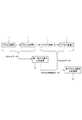
図1は、本発明の第1の実施形態であるプロセス異常分析装置を含む製造システムを示す。この製造システムは、複数のプロセス装置1,プロセス異常分析装置20及び異常表示装置2を含む。これらの装置は、生産管理情報よりも詳細なプロセス関連情報を高速にやりとりするための装置用ネットワークであるEES(Equipment Engineering System)ネットワーク3によって相互に接続されている。図示は省略されているが、EESネットワーク3には、プロセス装置1より前の段階、及びプロセス装置1より後の段階で用いられる他のプロセス装置や検査装置も接続されている。さらに、このシステムは、MES(Manufacturing Execution System)を含む生産管理システム4及びこの生産管理システム4と接続された生産管理情報を伝送するMES系ネットワーク5を含んでいる。EESネットワーク3とMES系ネットワーク5とは、ルータ6を介して接続されている。MES系ネットワーク5上に存在する生産管理システム4は、ルータ6を経由して、EESネットワーク3上の各装置にアクセスすることができる。 FIG. 1 shows a manufacturing system including a process abnormality analysis apparatus according to a first embodiment of the present invention. The manufacturing system includes a plurality of
この製造システムは、例えば、半導体や液晶パネルを製造するもので、プロセス装置1が半導体等を製造するためのプロセス(ウエハに対する成膜処理等)を実行する。半導体製造プロセスや液晶パネル製造システムにおいては、処理対象のウエハやガラス基板(以下、「ウエハ」)は、カセット10内に所定枚数セットされ、カセット単位で移動されるとともに、プロセス装置1で所定の処理が行なわれる。1つの製品を製造する場合、複数のプロセス装置1においてそれぞれ所定の処理が実行される。その場合、プロセス装置間の移動も、カセット単位で行なわれる。カセット10に実装された所定枚数のウエハが同一のロットとなる。 This manufacturing system manufactures a semiconductor and a liquid crystal panel, for example, and the
この実施形態の半導体製造システムでは、個々のウエハごとに管理する必要から、各ウエハごとに製品IDが付与される。この製品IDは、例えばロットIDと、そのロット内の識別番号を結合することにより、設定できる。すなわち、仮にロットIDが「0408251」で、ロット内にセット可能な枚数が1桁とすると、ロット内の2番目のガラス基板(ロット内の識別番号は「2」)の製品IDは、下一桁にロット内の識別番号を付加した「04082512」と設定することができる。 In the semiconductor manufacturing system of this embodiment, since it is necessary to manage each wafer, a product ID is assigned to each wafer. This product ID can be set, for example, by combining a lot ID and an identification number in the lot. That is, if the lot ID is “0408251” and the number of sheets that can be set in the lot is one digit, the product ID of the second glass substrate in the lot (the identification number in the lot is “2”) is It can be set to “04082512” with the identification number in the lot added to the digit.
もちろん、タグ10aに、ロットIDに替えて、或いはロットIDとともに収納された全てのウエハについての製品IDを記録しておき、プロセス装置1(プロセスデータ収集装置12)は、タグ10aに格納された全ての製品IDを取得するようにしてもよい。また、カセット10にセットするウエハが1枚の場合には、タグ10aに記録したIDが、そのまま製品IDとして使用できる。なお、ロット単位で解析をする場合には、製品IDの取得や、ロットIDに基づく製品IDの作成は不要である。 Of course, the product IDs of all wafers stored in the
カセット10には、RF−ID(radio frequency identification)タグ10aが取り付けられている。タグ10aは、プロセス装置1に連結されたRF−IDリードライトヘッド11との間で電磁結合をし、非接触で任意のデータを読み書きされるものであり、データキャリアとも呼ばれる。タグ10aには、ロットID(製品IDの基となるロットID或いは製品ID自体)と、前段装置の出庫時刻等の情報が格納される。 An RF-ID (radio frequency identification)
プロセス装置1は、MES系ネットワーク5からルータ6経由で生産管理システム4から送られてきたレシピIDを取得する。プロセス装置1は、レシピIDと実際に行なうプロセスとの対応テーブルなどを持っており、取得したレシピIDに応じたプロセスを実行する。複数のプロセス装置1は、それぞれの装置を識別するための装置IDが設定されている。 The
複数のプロセス装置1は、プロセスデータ収集装置12に接続されている。このプロセスデータ収集装置12は、EESネットワーク3に接続されている。プロセスデータ収集装置12は、各プロセス装置1においてプロセスが実行されている期間中或いは待機中に、プロセス装置1の状態に関連する情報であるプロセスデータを時系列に収集する。プロセスデータは、例えば、プロセス装置1の動作時の電圧,電流や、あるプロセスを実行するプロセス装置1を出庫してから次のプロセスを実行するプロセス装置1に投入されるまでの滞留時間などがある。また、プロセス装置1がプラズマチャンバーを備え、ウエハに対して成膜処理をする装置の場合、そのプラズマチャンバー内の圧力や、プラズマチャンバーに供給するガス流量や、ウエハ温度やプラズマ光量等がある。プロセス装置1は、これらのプロセスデータを検出するための検出装置を備え、その検出装置の出力が、プロセスデータ収集装置12に与えられる。 The plurality of
プロセスデータ収集装置12は、RF−IDリードライトヘッド11を介してタグ10aから読み取った前段装置の出庫時刻と現在ウエハがセットされているプロセス装置1への投入時刻とを収集する。これらの出庫時刻と投入時刻の差をとることにより、前段装置からの滞留時間を算出することができる。また、RF−IDリードライトヘッド11は、必要に応じてプロセス装置1からウエハを出庫する際に出庫時刻等をタグ10aへ書き込む。 The process
プロセスデータ収集装置12は、通信機能を備えている。プロセスデータ収集装置12は、プロセス装置1において発生したあらゆるプロセスデータを収集し、収集したプロセスデータに製品IDと装置IDとを対応付けてEES系ネットワーク3に出力する。収集するデータの種類は、上記のものに限るものではなく、さらに多くの情報を取得することも妨げない。 The process
プロセス異常分析装置20は、ハードウェアの観点からは一般的なパーソナル・コンピュータであり、Windows(登録商標)などのオペレーティング・システム上で稼動するアプリケーション・プログラムによって、本装置の各機能が実現されている。 The process
図2は、プロセス異常分析装置20の内部構成を示している。プロセス異常分析装置20は、プロセスデータ収集装置12から送られてきた各プロセス装置ごとのプロセスデータを格納する複数のプロセスデータ記憶部21と、各プロセスデータ記憶部21に格納された各種のプロセスデータからプロセス特徴量を算出するプロセスデータ編集部22と、プロセスデータ編集部22が算出した各プロセス装置ごとのプロセス特徴量を格納する複数のプロセス特徴量データ記憶部23と、その複数のプロセス特徴量データ記憶部23にアクセスし同一のウエハについてのプロセス特徴量を抽出すると共に統合するプロセス特徴量統合部30と、そのプロセス特徴量統合部30で統合された統合プロセス特徴量データを格納する統合データ記憶部31と、統合データ記憶部31に格納された統合プロセス特徴量データに基づいて異常の有無を判定する異常判定部24と、異常判定部24で異常と判定されたウエハについてのプロセスデータを記憶する異常プロセスデータ記憶部27と、異常判定部24で異常と判定された異常要因を記憶する異常要因データ記憶部28と、異常判定部24で判定処理を行なう際に使用する異常分析ルールを記憶する異常分析ルールデータ記憶部26と、その異常分析ルールデータ記憶部26にアクセスして異常分析ルールの追加・変更を行なう異常分析ルール編集部25と、を備えている。 FIG. 2 shows the internal configuration of the process
各記憶部は、プロセス異常分析装置20の外部の記憶装置(データベース20a)に設定してもよいし、内部記憶装置に設けてもよい。プロセスデータ記憶部21のように同種の記憶部が複数存在する場合、物理的に1つの記憶装置を用いるのを妨げない。 Each storage unit may be set in a storage device (
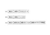
図3(a)に示すように、プロセスデータ記憶部21に格納されるプロセスデータは、製品IDと装置IDとに関連付けられる。プロセスデータは、プロセスデータ収集装置12が収集した各種のプロセスデータに加え、そのプロセスデータを収集した日時情報(日付+時刻)も含む。各プロセス装置用のプロセスデータ記憶部21には、製品IDごとに、日時情報に従って時系列にプロセスデータが格納される。 As shown in FIG. 3A, the process data stored in the process
プロセスデータ記憶部21は、リングバッファ等の一時記憶手段から構成され、プロセス終了後の所定のタイミングでプロセスデータを削除(新たなプロセスデータを上書き)するようにしている。 The process
プロセスデータ編集部22は、プロセスデータ記憶部21に格納された時系列のプロセスデータを呼び出し、枚葉毎のプロセス特徴量を算出する。プロセス特徴量は、例えば、同一の製品IDについてのプロセスデータのピーク値,総和,平均値等のプロセスデータの値から算出するものに限らず、プロセスデータの値が設定された閾値を超えている時間等の各種のものがある。 The process data editing unit 22 calls time-series process data stored in the process
プロセスデータ編集部22は、生産管理システム4から出力されるレシピIDを製品ID並びに装置IDとともに取得する。レシピは、予め決められたプロセス装置に対する命令や設定、パラメータのセットで、処理対象や工程、装置の違いにより複数持ち、生産管理システム4で管理される。それぞれのレシピには、レシピIDが付与される。各プロセス装置1で処理されるウエハに対するレシピは、装置IDと製品IDとレシピIDとにより特定される。 The process data editing unit 22 acquires the recipe ID output from the
プロセスデータ編集部22は、図3(b)に示す製品IDと装置IDとレシピIDとのセットを以下に示す手順で取得する。まず、プロセスデータ編集部22は、生産管理システム(MES)4にアクセスし、分析対象のウエハの製品IDと、プロセス装置1を特定する装置IDをキーにし、対応するレシピIDを検索する。次いで、プロセスデータ編集部22は、その検索したレシピIDを生産管理システム4から直接、或いは、プロセスデータ収集装置12経由で取得する。プロセスデータ収集装置12経由で取得する場合、プロセスデータ収集装置12は、進行中のプロセスのレシピIDを生産管理システム(MES)4から取得し、プロセス装置1の装置IDとプロセスデータとを併せてプロセス異常分析装置20へ渡すようにしてもよい。 The process data editing unit 22 acquires a set of the product ID, the device ID, and the recipe ID shown in FIG. First, the process data editing unit 22 accesses the production management system (MES) 4 and searches for the corresponding recipe ID using the product ID of the wafer to be analyzed and the apparatus ID that identifies the
プロセスデータ編集部22は、製品IDと装置IDをキーにして、算出したプロセス特徴量データと、取得したレシピIDとを結合し、その結合したデータを対応する装置ID用のプロセス特徴量データ記憶部23に格納する。よって、プロセス特徴量データ記憶部23のデータ構造は、図3(c)に示すようになる。 The process data editing unit 22 combines the calculated process feature data and the acquired recipe ID using the product ID and the device ID as keys, and stores the combined data for the process feature data for the corresponding device ID. Stored in the
プロセス特徴量統合部30は、プロセス特徴量データベース23にアクセスし、あらかじめ定義されたプロセス特徴量統合定義データに従い、製品IDが共通のプロセス特徴量を抽出し、それらを統合する。この統合された統合プロセス特徴量データは、図4に示すように、製品IDと、そのウエハの製造に関与したプロセス装置の装置IDと、そのプロセス装置から生成されたプロセス特徴量データとを関連づけたデータ構造となる。この統合プロセス特徴量データは、統合データ記憶部31に格納される。また、プロセス特徴量統合部30の実行時に、処理対象のウエハについての全てのプロセス特徴量が生成されているとは限らない。そこで、プロセス特徴量統合部30は、抽出したプロセス特徴量データの製品IDに該当する統合プロセス特徴量データが統合データ記憶部32にすでに登録されているか否かを判断し、未登録の場合には統合した統合プロセス特徴量データを新規のデータとして登録し、すでに登録済みの場合には、その登録された統合プロセス特徴量データを読み出すとともに、プロセス特徴量データの装置IDとプロセス特徴量とを結合する。 The process feature
プロセス特徴量統合定義データは、プロセス特徴量統合定義データ記憶部32に登録されている。このプロセス特徴量統合定義データは、具体的に統合する製品IDと装置IDとの組み合わせについて記述したものでも良いし、上述した一般的なルール、すなわち、「製品IDが同じものを統合し、統合データ記憶部32に未登録の場合には新規に登録し、登録済みの場合には既存の統合プロセス特徴量データに結合する」でもよい。 The process feature quantity integration definition data is registered in the process feature quantity integration definition
異常分析ルール編集部25は、モデル化装置14や人手による解析によって得られたモデルを取得し、異常分析ルールを定義し、異常分析ルールデータ記憶部26に格納する。モデル化装置14は、例えば特開2004−186445号公報に開示されたデータマイニングを利用したモデル化装置等を用いることができる。ここでデータマイニングとは、大規模なデータベースからルールやパターンを抽出する手法であり、その具体的な手法としては、決定木分析と呼ばれる手法及び回帰木分析と呼ばれる手法等が知られている。 The abnormality analysis
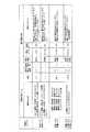
さらに異常分析ルール編集部25は、異常分析ルールに対応する異常通知情報も登録する。これにより、異常分析ルールデータ記憶部26のデータ構造は、図5に示すように、各プロセス装置の装置IDと、各プロセス装置のレシピIDと、異常分析ルールと、異常通知情報と、を関連付けたテーブル構造となる。 Furthermore, the abnormality analysis
異常通知情報は、異常分析ルールに基づいて判定された結果を表示する異常表示装置2や、判定結果を通知する通知先等の出力先を特定する情報と、具体的な通知内容がある。通知先は、例えば、担当者のメールアドレスなどである。異常表示装置2と通知先の両方を登録しても良いし、一方のみを登録しても良い。出力先を複数設けた場合、例えば、判定により求められる異常の度合いや異常箇所などで分類し、分類に応じて振り分けることができる。異常表示装置,通知先、通知内容は、ひとつの分類に対し、複数指定することができる。異常分析ルールは、線形回帰,決定木,マハラノビスの距離,主成分分析,移動主成分分析,DISSIMなどの手法を使用することができる。 The abnormality notification information includes an
図6は、異常分析ルールデータ記憶部26に格納されるデータ(レシピID,装置ID,異常分析ルール,異常通知情報)の具体例を示している。図示するように、異常分析ルールは、プロセス特徴量に基づいて演算処理する異常判定式と、その異常判定式により求めた値(y)が異常を生じているか否かを決定する判定条件と、を備えている。 FIG. 6 shows a specific example of data (recipe ID, device ID, abnormality analysis rule, abnormality notification information) stored in the abnormality analysis rule
この異常分析ルールは、プロセス特徴量から異常検出や異常要因分析を行なうためのルールである。異常検出は、異常の有無を判断するものである。図6に示す例では、上の2つの異常分析ルールが、装置A,装置Bの組み合わせについての異常検出をするためのルールである。これらのルールでは、異常箇所も具体的に特定できる。一番下の異常分析ルールは、装置D,装置E,装置Fの組み合わせについての異常検出を行なうためのルールである。但し、この異常分析ルールでは、複数の異常要因から総合的に判断しているので、異常個所を特定することはできない。 This abnormality analysis rule is a rule for performing abnormality detection and abnormality factor analysis from the process feature amount. Abnormality detection is to determine the presence or absence of abnormality. In the example shown in FIG. 6, the above two abnormality analysis rules are rules for detecting an abnormality for the combination of the devices A and B. With these rules, the abnormal location can also be specifically identified. The lowest abnormality analysis rule is a rule for detecting an abnormality for the combination of the devices D, E, and F. However, in this abnormality analysis rule, since it is judged comprehensively from a plurality of abnormality factors, the abnormal part cannot be specified.
異常要因分析は、異常要因データを求めるものである。異常要因データは、プロセスデータまたはその特徴量を示す名称と寄与率データを含む。寄与率データは、その異常に対して、どのプロセスデータやその特徴量がどのくらい影響を与えているかを表わすデータである。寄与率データの数値が大きいほど当該異常に対する影響度合いが大きい、すなわち当該異常をもたらした原因の可能性が高いと言える。異常要因分析により算出される寄与率データの値の上位N個(例えば、5個)までの寄与率データを含む異常要因データを抽出する。作業員は、抽出された異常要因データに基づき、異常が検出されたときの対処時に、どのプロセスデータをチェックすればよいかがわかる。 The abnormality factor analysis is to obtain abnormality factor data. The abnormality factor data includes process data or a name indicating the feature amount and contribution rate data. The contribution rate data is data representing how much process data and its feature amount influence the abnormality. It can be said that the greater the numerical value of the contribution rate data, the greater the degree of influence on the abnormality, that is, the higher the possibility of the cause of the abnormality. Abnormality factor data including up to the top N (for example, five) contribution rate data values of the contribution rate data calculated by the abnormality factor analysis is extracted. Based on the extracted abnormality factor data, the worker knows which process data should be checked when dealing with an abnormality detected.
本実施形態では、異常要因データを決定するための寄与率を、PLS(Partial Least Squares)法により得られた回帰式より求めるようにした。このPLS法により得られる回帰式を下記に示す。
y=b0+b1*x1+b2*x2+……+b(n−1)*x(n−1)+bn*xn
上記の式において、x1,x2,……xnが、それぞれプロセス特徴量であり、b0,b1,b2,……bnは、係数である。b1,b2,……bnは、各プロセス特徴量の重み度である。上記の回帰式により求めたyの値がしきい値を越えた場合に異常と判定される。このPLS法を用いた異常検知は、例えば、特開2004−349419の段落[0080]−[0093]等に開示されている。In the present embodiment, the contribution rate for determining the abnormality factor data is obtained from a regression equation obtained by the PLS (Partial Last Squares) method. The regression equation obtained by this PLS method is shown below.
y = b0 + b1 * x1 + b2 * x2 + ... + b (n-1) * x (n-1) + bn * xn
In the above equations, x1, x2,... Xn are process feature quantities, and b0, b1, b2,. b1, b2,..., bn are the weights of each process feature amount. When the value of y obtained by the above regression equation exceeds the threshold value, it is determined as abnormal. Anomaly detection using this PLS method is disclosed in paragraphs [0080]-[0093] of JP-A-2004-349419, for example.
本実施形態では、このPLS法を利用して各プロセス特徴量の寄与率を求めるようにした。まず、各変数(x1,x2,……xn)がいずれも平均値を示すときのPLS予測値をYとする。そして、実際に取得したプロセス特徴量を各変数に代入して求めたyとの差であるy−Yの大きさに各項がどれだけ寄与したかを評価する。つまり、各変数の平均値をX1,X2,……Xnとすると、上記の式の各項の値は、下記のようになる。
b1(x1−X1)、b2(x2−X2)、・・・・、bn(xn−Xn)
このように、平均値と実測値の差分に、さらに係数を乗算した値を求めた各項の値を、各プロセス特徴量の寄与率データとした。In the present embodiment, the contribution rate of each process feature amount is obtained using this PLS method. First, assume that the PLS predicted value when each variable (x1, x2,... Xn) shows an average value is Y. Then, how much each term contributes to the magnitude of yY, which is the difference from y obtained by substituting the actually acquired process feature quantity into each variable, is evaluated. That is, assuming that the average value of each variable is X1, X2,... Xn, the value of each term in the above equation is as follows.
b1 (x1-X1), b2 (x2-X2), ..., bn (xn-Xn)
As described above, the value of each term obtained by multiplying the difference between the average value and the actual measurement value by the coefficient is used as contribution rate data of each process feature amount.
この寄与率を用いた要因分析は、図6におけるレシピID=4001が該当する。このレシピID=4001の異常分析ルールでは、具体的な異常箇所までは特定できないものの、複数の異常要因をリストアップすることができる。Temperature,FlowRate,Pressureは、はそれぞれプロセスデータである温度、ガス流量、ガス圧から求めたプロセス特徴量である。 The factor analysis using this contribution rate corresponds to recipe ID = 4001 in FIG. In this abnormality analysis rule of recipe ID = 4001, although a specific abnormality location cannot be specified, a plurality of abnormality factors can be listed. “Temperature”, “FlowRate”, and “Pressure” are process feature amounts obtained from temperature, gas flow rate, and gas pressure, which are process data, respectively.
本実施形態では、複数のプロセス装置のプロセス特徴量が統合された統合プロセス特徴量データに基づいて異常判定を行なうため、要因分析を行なった結果、異常を生じているおそれが高いプロセス装置を特定したり、そのプロセス装置のどのプロセス特徴量が問題であるかを特定することができる。 In this embodiment, since abnormality determination is performed based on integrated process feature data in which process feature values of a plurality of process devices are integrated, a process device having a high possibility of causing an abnormality is identified as a result of factor analysis. Or which process feature quantity of the process apparatus is a problem.
異常分析ルール編集部25の具体的な処理機能は、図7に示すフローチャートを実行するようになっている。まず、異常分析ルール編集部25は、新規作成か更新処理かを判断する(S11)。この判断は、例えば異常分析ルール編集部25が、プロセス異常分析装置20を構成するパソコンの表示装置に、「新規作成」ボタンと「更新処理」ボタンとを含む入力画面を表示させ、どちらのボタンが選択されかを認識することで行なう。 A specific processing function of the abnormality analysis
新規作成の場合、異常分析ルール編集部25は、各プロセス装置の装置IDと、各プロセス装置のレシピIDと、異常分析ルールと、異常通知情報と、を関連付ける(S12)。具体的には、異常分析ルール編集部25がモデル化装置14から与えられる装置IDと、レシピIDと、モデルと、異常通知情報とを取得することで、関連づけが行なえる。異常分析ルールは、モデルから特定される。モデル作成装置14から与えられる異常通知情報に未登録の項目が存在する場合、異常分析ルール編集部25は、取得した情報を表示装置に表示する。この表示装置に表示する表示形態は、例えば、図6に示すような表形式とし、未登録の項目を空欄にする。ユーザは、プロセス異常分析装置20を構成するパソコンの入力装置を操作し、未登録の項目について入力する。異常分析ルール編集部25は、その入力された情報とモデル化装置14から取得した情報を関連づける。この未登録の項目は、例えば、異常通知先や、異常情報を表示する異常表示装置を特定するための情報など、ユーザ側で設定可能なものである。もちろん、モデル化装置14が、異常通知情報の全ての項目を作成しても良い。モデル化装置14で作成されたモデル等は、異常分析ルール編集部25に対してオンラインで与えられるようにしても良いし、そのモデル等をオペレータが入力するといったオフラインで与えるようにしても良い。 In the case of new creation, the abnormality analysis
異常分析ルール編集部25は、処理ステップS12を実行して関連づけたデータを新規ルールデータとして異常分析ルールデータ記憶部26に保存し、新規作成処理を終了する(S13)。 The abnormality analysis
更新処理の場合、処理ステップS11の分岐判断がNoとなるので、異常分析ルール編集部25は、異常分析ルールデータ記憶部26にアクセスし、既存のルールデータを読み出す(S14)。この読み出しは、編集対象のレシピID等がわかっている場合には、そのレシピID等をキーにして検索し、該当するルールデータを読み出すことができるし、全てのデータを読み出すこともできる。全てのルールデータを読み出した場合、異常分析ルール編集部25は、例えば、図6に示すような表形式で表示装置に出力する。 In the case of update processing, the branch determination in process step S11 is No, so the abnormality analysis
次いで、異常分析ルール編集部25は、読み出したルールデータの修正(追加、変更、削除)を行ない(S15)、修正したルールデータを異常分析ルールデータ記憶部26に保存し(S16)、更新処理を終了する。 Next, the abnormality analysis
異常判定部24は、異常分析部24aと、異常プロセスデータ保存部24bと、異常表示部24cと、異常通知部24dと、異常要因保存部24eと、を備えている。異常分析部24aは、異常分析ルールデータ記憶部26に格納された異常分析ルールを用い、プロセス特徴量データ記憶部23から読み出したプロセス特徴量に従って異常判定を行なう。この異常分析部24aで実行される異常判定は、異常の有無と、異常要因分析の両方である。 The
異常プロセスデータ保存部24bは、異常分析部24aで異常が検出された場合に、その異常と判定されたウエハについてのプロセスデータをプロセスデータ記憶部21から読み出すとともに、異常プロセスデータとして異常プロセスデータ記憶部25に保存する。このとき、異常判定結果(yの値)を関連づけて登録しても良い。 When an abnormality is detected by the
異常表示部24cは、異常判定部24aで異常が検出された場合に、指定された異常表示装置に対して異常メッセージを出力する。出力する異常メッセージは、異常分析ルールデータ記憶部26に格納されている。また、異常要因分析を行なった場合、寄与率等の詳細データも併せて出力する。 The
異常通知部24dは、異常分析部24aで異常が検出された場合に、指定された異常通知先に対して指定された方法で異常メッセージを出力する。一例としては、異常通知部24dは、指定されたアドレスに対してメール送信をする。出力する異常メッセージは、異常分析ルールデータ記憶部26に格納されている。また、異常要因分析を行なった場合、寄与率等の詳細データも併せて出力する。 When an abnormality is detected by the
異常要因保存部24eは、異常分析部24aにおける異常判定の結果、寄与率などの異常要因情報が存在する場合に、その情報を異常要因データとして異常要因データ記憶部28に保存する。 When there is abnormality factor information such as a contribution rate as a result of the abnormality determination in the
この異常判定部24の具体的な処理機能は、図8に示すフローチャートのようになっている。まず、異常分析部24aは、統合データ記憶部31にアクセスし、1つの製品IDをキーにして1枚葉分の統合プロセス特徴量データを抽出し、そのレシピ情報を取得する(S1)。 The specific processing function of the
異常分析部24aは、異常分析ルールデータ記憶部26にアクセスし、取得したレシピIDと装置IDに対応する異常分析ルールを取得する(S2)。異常分析部24aは、取得した異常分析ルールの異常判定式に統合プロセス特徴量データを代入し、yの値を算出する(S3)。 The
異常分析部24aは、その判定条件に基づいて異常の有無を判断する(S4)。例えば、レシピID=1001の場合、判定条件が4つ存在するため、処理ステップS3を実行して異常判定式からyの値を算出したならば、そのyの値が、どの判定条件に合致するかを順番にチェックする。また、レシピID=4001の場合は、主成分分析を行ない、yの値が判定条件の0.8以上になった場合、併せて各異常要因データに含まれる寄与率データを確認し、寄与率データの値が上位N個分に該当する異常要因データを抽出する。Nの値は、任意に設定でき、例えば5個とすることができるし、全ての異常要因データを抽出する(N=n)ようにしても良い。 The
異常が検出された場合(S4でYes)、判定条件に対応する異常通知情報に従って異常を通知する(S5)。具体的には、異常表示部24cは、予め設定された異常表示装置2に対してメッセージを出力し、異常通知部24dは、予め設定された異常通知先にメール送信等により通知する。通知する内容は、異常分析ルールデータ記憶部26に格納された異常表示情報と、レシピIDに加え、発生日時情報や異常通知IDを付加する。 When an abnormality is detected (Yes in S4), an abnormality is notified according to the abnormality notification information corresponding to the determination condition (S5). Specifically, the
異常表示部24cから出力された異常通知に基づいて異常表示装置2の表示装置に表示される表示例としては、図9に示すようにテーブル形式とすることができる。図9では、複数の異常通知を一覧表示した例を示しているが、実際には、異常表示部24cからリアルタイムで異常通知が送られてくるため、送られてきた情報を順次一覧に追加して表示することになる。もちろん、異常表示装置2が、送られてきた異常通知情報等を記憶装置に格納し、後で一覧表示することもできる。また、図示省略するが、異常表示部24cや異常通知部24dが出力する内容を、プロセス異常分析装置20に設けたデータベースに格納し、管理するようにしても良い。 As a display example displayed on the display device of the
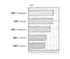
また、図9に示すように、異常表示部24cが出力する情報の中には、異常要因の有無の情報も備えており、図9中、異常通知ID=20041124001のように、要因情報が有る場合、要因変数と寄与率も併せて出力する。よって、異常表示装置2は、取得した要因変数と寄与率に基づき、例えば図10に示すように、上位n個(この例では5個)のデータを棒グラフで表示する。これにより、ユーザは、どの要因変数、すなわち、どのプロセス装置のプロセス特徴量が異常発生の原因になっている可能性が高いかを、一目で理解することができる。もちろん、この要因変数と寄与率の表示形態は、棒グラフに限ることはなく、円グラフその他のグラフで表示したり、図11に示すように、表形式でテキスト表示するようにしてもよく、各種の表示形態を採ることができる。 As shown in FIG. 9, the information output from the
さらに、異常プロセスデータ保存部24bは、異常と判定された製品IDをキーにプロセスデータ記憶部21にアクセスし、該当するプロセスデータを取得するとともに、異常プロセスデータとして異常プロセスデータ保存部27に格納する(S6)。 Further, the abnormal process
この異常プロセスデータ記憶部27に格納された異常プロセスデータは、モデル化装置14に読み出され、そこにおいて解析され、新たなモデルを生成したり、既存のモデルを修正するための情報に利用される。また、係る解析は、モデル化装置14による自動的に行なうものに限らず、人間が解析して新たなモデルを作成することもできる。これら再解析によって作成されたモデルは、異常分析ルール編集部25を介して異常分析ルールデータ記憶部26に格納され、それ以後の異常判定に利用される。 The abnormal process data stored in the abnormal process
このようにすると、異常と判定されたウエハについてのプロセスデータを異常プロセスデータとして異常プロセスデータ記憶部27に記憶保持することができるため、データ量が膨大なプロセスデータの生データのうち異常時のもののみを保存することができ、ハードディスクなどの物理記憶装置の容量を節約することができる。 In this way, the process data for the wafer determined to be abnormal can be stored and held in the abnormal process
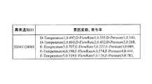
処理ステップS6を実行後、異常要因情報がある場合に異常要因保存部24eが異常要因データを異常要因データ記憶部28に保存する処理を実行する(S7)。異常要因データ記憶部28に保存される異常要因データのデータ構造は、図12に示すようになっている。図示するように、異常通知IDと、発生日と、発生時刻と、異常を発生した装置IDと、レシピIDと、製品IDと、異常レベルと、異常コードと、メッセージと、要因変数,寄与率と、を関連付けたテーブルからなる。装置ID,レシピID,製品ID,異常レベル,異常コード,メッセージは、異常分析ルールデータ記憶部に格納された異常通知情報から生成され、発生日と発生時刻は、装置が持つ内部時計に基づいて生成され、異常通知IDは、異常分析部24aが発生日と、その発生日における3桁のレコード番号とを結合することで生成する。図示の例では、2004年11月24日の1番目に発生された異常通知を意味する。要因変数,寄与率は、異常分析部24aで算出された各要因変数の寄与率のうち、上位N個(N=nを含む)を抽出し、要因変数とセットで異常要因データ記憶部28に登録される。この異常要因データ記憶部28に格納された異常要因データは、異常表示装置2や、モデル化装置14等の外部の装置から検索することができる。 After executing the processing step S6, when there is abnormality factor information, the abnormality
異常分析部24aは、異常分析ルールに含まれる全ての判定式の評価が完了したか判断する(S8)。完了していなければ(S8でNO)、次の判定式を取得し(S9)、すべての判定式による判定が完了するまで処理ステップS3以降を繰り返す。 The
上述した実施形態では、1つのプロセスデータ収集装置12が複数のプロセス装置のプロセスデータを収集するようにしたが、本発明はこれに限ることはなく、各プロセス装置にそれぞれプロセスデータ収集装置を接続し、1つのプロセスデータ収集装置が1つのプロセス装置のプロセスデータを収集するようにしても良い。この場合に、プロセスデータ収集装置は、プロセス装置に内蔵しても良いし、外付けとしても良い。 In the embodiment described above, one process
異常表示装置2の設置位置は、EESネットワーク3に限ることはなく、MES系ネットワーク5や、さらに外部のネットワークに接続してもよい。異常表示装置2とプロセス異常分析装置20とが、同一のパソコンにより構成されても良い。 The installation position of the
図13は、本発明の第2の実施形態を示している。本実施形態では、プロセス異常分析装置を複数個設定している。この例では、2つのプロセス装置1(A,B)のプロセスデータを第1プロセス異常分析装置20′に与え、他の2つのプロセス装置1(C,D)のプロセスデータを第2プロセス異常分析装置20″に与える。さらに、本実施形態では、第1プロセス異常分析装置20′で作成したプロセス特徴量データを、第2プロセス異常分析装置20″に渡し、第2プロセス異常分析装置20″のプロセス特徴量データ記憶部23に格納するようにしている。なお、図13は、プロセスデータ収集装置の図示を省略している。 FIG. 13 shows a second embodiment of the present invention. In this embodiment, a plurality of process abnormality analyzers are set. In this example, the process data of the two process devices 1 (A, B) is given to the first process
これにより、第1プロセス異常分析装置20′は、プロセス装置Aとプロセス装置Bの2つのプロセス装置から収集したプロセスデータからそれぞれのプロセス特徴量データを生成し、各プロセス特徴量データに基づいて統合プロセス特徴量データを生成する。そして、第1プロセス異常分析装置20′は、その生成した統合プロセス特徴量データに基づいて異常分析を行なう。第1プロセス異常分析装置20′は、生成したプロセス装置Aとプロセス装置Bについてのプロセス特徴量データを第2プロセス異常分析装置20″に送る。 As a result, the first
第2プロセス異常分析装置20″は、第1プロセス異常分析装置20′から取得したプロセス装置Aとプロセス装置Bについてのプロセス特徴量データをプロセス特徴量データ記憶部23に格納する。第2プロセス異常分析装置20″は、プロセス装置Cとプロセス装置Dの2つのプロセス装置から収集したプロセスデータからそれぞれのプロセス特徴量データを生成し、プロセス特徴量データ記憶部23に格納する。第2プロセス異常分析装置20′のプロセス特徴量統合部30は、4つのプロセス装置についてのプロセス特徴量データに基づいて統合プロセス特徴量データを生成する。これにより、第2プロセス異常分析装置20″は、4つのプロセス装置のプロセス特徴量データを統合した統合プロセス特徴量データに基づいて異常分析を行なうことができる。プロセス装置Aとプロセス装置Bについてのプロセス特徴量データは、第1プロセス異常分析装置20′で生成したものを利用するため、当該プロセス特徴量データを第2プロセス異常分析装置20″で再度生成する必要が無く、負荷が軽減する。 The second
図14は、本実施形態に用いられるプロセス異常分析装置20′,20″の内部構造を示すブロック図である。図に示すように、プロセス異常分析装置20′,20″は、別のプロセス異常分析装置20から送られてきたプロセス特徴量データを、プロセス特徴量データ記憶部23に格納する。また、プロセス異常分析装置20′,20″は、所定のプロセス装置のプロセス特徴量データをプロセス特徴量データ記憶部23から読み出すと共に、他のプロセス異常分析装置20に出力するプロセス特徴量データ出力部33を備えている。このプロセス特徴量データ出力部33は、自己が保有するプロセス特徴量データのうち、どのプロセス装置についてのデータをどのプロセス異常分析装置へ送るかの情報を持ち、その情報に基づいて出力処理を実行する。 FIG. 14 is a block diagram showing the internal structure of the
また、本実施形態では、他のプロセス異常分析装置が生成したプロセス特徴量データを一旦自己のプロセス特徴量データ記憶部に格納するようにしたが、本発明はこれに限ることはなく、たとえば、プロセス特徴量データ統合部31が、他のプロセス異常分析装置のプロセス特徴量データ記憶部にアクセスし、そこに格納された必要なプロセス特徴量データを読み出し、自己が持つプロセス特徴量データと統合するようにしても良い。 Further, in the present embodiment, the process feature amount data generated by another process abnormality analyzer is temporarily stored in its own process feature amount data storage unit, but the present invention is not limited to this, for example, The process feature value
別のプロセス異常分析装置が生成したプロセス特徴量データを利用することにより、1または複数のプロセス異常分析装置をプロセス装置に内蔵させることもできる。すなわち、例えばプロセス装置に第1プロセス異常分析装置20′を内蔵させるとともに、EESネットワーク3に第2プロセス異常分析装置20″を接続する。第1プロセス異常分析装置20′は、実装されたプロセス装置からのプロセスデータに基づき異常判定を行なうとともに、当該プロセス装置のプロセス特徴量データを第2プロセス異常分析装置20″に与える。第2プロセス異常分析装置20″は、取得したプロセス特徴量データと、EESネットワーク3を介して取得したプロセス装置のプロセスデータから生成したプロセス特徴量データと、を統合し、得られた統合プロセス特徴量データに基づいて異常判定を行なう。もちろん、プロセス装置に内蔵された第1プロセス異常分析装置20′が、別のプロセス異常分析装置からプロセス特徴量データを取得し、異常判定を行なうようにしても良い。 By using the process feature amount data generated by another process abnormality analyzer, one or more process abnormality analyzers can be incorporated in the process apparatus. That is, for example, the first process
20 プロセス異常分析装置
21 プロセスデータ記憶部
22 プロセスデータ編集部
23 プロセス特徴量データ記憶部
24 異常判定部
24a 異常分析部
24b 異常プロセスデータ保存部
24c 異常表示部
24d 異常通知部
24e 異常要因保存部
25 異常分析ルール編集部
26 異常分析ルールデータ記憶部
27 異常プロセスデータ記憶部
28 異常要因データ記憶部
30 プロセス特徴量統合部
31 統合データ記憶部
32 プロセス特徴量統合定義データ記憶部
33 プロセス特徴量データ出力部DESCRIPTION OF
Claims (5)
Translated fromJapanese前記複数の製造装置のプロセスデータから算出された製造装置ごとのプロセス特徴量データを統合し、統合プロセス特徴量データを生成するプロセス特徴量統合手段と、
統合プロセス特徴量データから異常分析を行なうための異常分析ルールを記憶する異常分析ルールデータ記憶手段と、
前記異常分析ルールにより、前記統合プロセス特徴量データから異常分析する異常判定手段と、
前記異常判定手段により異常と判定された場合に、異常通知情報を出力する手段と、を備えたことを特徴とするプロセス異常分析装置。In a manufacturing system comprising a plurality of manufacturing apparatuses, a process abnormality analysis apparatus that detects a process abnormality for each unit target product based on process data obtained at the time of process execution,
Process feature value integration means for integrating process feature value data for each manufacturing device calculated from process data of the plurality of manufacturing devices and generating integrated process feature value data;
Anomaly analysis rule data storage means for storing an anomaly analysis rule for performing an anomaly analysis from the integrated process feature data;
Anomaly determination means for analyzing anomalies from the integrated process feature data according to the anomaly analysis rules;
And a means for outputting abnormality notification information when the abnormality determination means determines that an abnormality has occurred.
そのプロセスデータ記憶手段に格納された各製造装置のプロセスデータから各製造装置のプロセス特徴量データを算出するプロセスデータ編集手段と、を備え、
前記プロセス統合手段の統合対象のプロセス特徴量データは、前記プロセスデータ編集手段が求めた各製造装置のプロセス特徴量データを含むことを特徴とする請求項1に記載のプロセス異常分析装置。Process data storage means for collecting process data of each manufacturing apparatus obtained at the time of process execution of a plurality of manufacturing apparatuses and storing the obtained time-series process data;
Process data editing means for calculating process feature value data of each manufacturing apparatus from the process data of each manufacturing apparatus stored in the process data storage means,
2. The process abnormality analysis apparatus according to claim 1, wherein the process feature amount data to be integrated by the process integration unit includes process feature amount data of each manufacturing apparatus obtained by the process data editing unit.
プロセス実行時に得られるプロセスデータに基づいてプロセスの異常を単位対象品毎に検出するプロセス異常分析装置を複数備え、
その複数のプロセス異常分析装置のうちの少なくとも1つは請求項3に記載のプロセス常分析装置であることを特徴とするプロセス異常分析システム。In a manufacturing system composed of a plurality of manufacturing devices, a process abnormality analysis system that detects a process abnormality for each unit target product based on process data obtained during process execution,
Equipped with multiple process abnormality analysis devices that detect process abnormality for each unit target product based on process data obtained at the time of process execution,
The process abnormality analysis system according to claim 3, wherein at least one of the plurality of process abnormality analysis apparatuses is the process abnormality analysis apparatus according to claim 3.
前記複数の製造装置のプロセスデータから算出された製造装置ごとのプロセス特徴量データを統合し、統合プロセス特徴量データを生成するプロセス特徴量統合手段、
統合プロセス特徴量データから異常分析を行なうための異常分析ルールを記憶する異常分析ルールデータ記憶手段、
前記異常分析ルールにより、前記統合プロセス特徴量データから異常分析する異常判定手段、
前記異常判定手段により異常と判定された場合に、異常通知情報を出力する手段、として機能させるためのプログラム。Computer
Process feature value integration means for integrating process feature value data for each manufacturing device calculated from process data of the plurality of manufacturing devices, and generating integrated process feature value data;
Anomaly analysis rule data storage means for storing an anomaly analysis rule for performing an anomaly analysis from the integrated process feature data;
An abnormality determination means for analyzing an abnormality from the integrated process feature data according to the abnormality analysis rule,
A program for functioning as means for outputting abnormality notification information when the abnormality determination means determines that an abnormality has occurred.
Priority Applications (4)
| Application Number | Priority Date | Filing Date | Title |
|---|---|---|---|
| JP2006037588AJP2007219692A (en) | 2006-02-15 | 2006-02-15 | Process abnormality analyzing device, process abnormality analyzing system and program |
| KR1020070003698AKR100867267B1 (en) | 2006-02-15 | 2007-01-12 | Apparatus of analysis trouble process and thereof system, program and method |
| US11/705,598US20070192064A1 (en) | 2006-02-15 | 2007-02-13 | Process fault analyzer and system, program and method thereof |
| TW096105382ATW200736950A (en) | 2006-02-15 | 2007-02-14 | Process abnormality-analyzing device, and system, program and method thereof |
Applications Claiming Priority (1)
| Application Number | Priority Date | Filing Date | Title |
|---|---|---|---|
| JP2006037588AJP2007219692A (en) | 2006-02-15 | 2006-02-15 | Process abnormality analyzing device, process abnormality analyzing system and program |
Publications (1)
| Publication Number | Publication Date |
|---|---|
| JP2007219692Atrue JP2007219692A (en) | 2007-08-30 |
Family
ID=38369784
Family Applications (1)
| Application Number | Title | Priority Date | Filing Date |
|---|---|---|---|
| JP2006037588APendingJP2007219692A (en) | 2006-02-15 | 2006-02-15 | Process abnormality analyzing device, process abnormality analyzing system and program |
Country Status (4)
| Country | Link |
|---|---|
| US (1) | US20070192064A1 (en) |
| JP (1) | JP2007219692A (en) |
| KR (1) | KR100867267B1 (en) |
| TW (1) | TW200736950A (en) |
Cited By (1)
| Publication number | Priority date | Publication date | Assignee | Title |
|---|---|---|---|---|
| JP2021168364A (en)* | 2020-04-13 | 2021-10-21 | キヤノン株式会社 | Information processing apparatus, detection method, program, substrate processing system and manufacturing method of article |
Families Citing this family (20)
| Publication number | Priority date | Publication date | Assignee | Title |
|---|---|---|---|---|
| US8295969B2 (en)* | 2007-07-27 | 2012-10-23 | Intermolecular, Inc. | Combinatorial processing management system |
| US8335582B2 (en)* | 2008-05-19 | 2012-12-18 | Applied Materials, Inc. | Software application to analyze event log and chart tool fail rate as function of chamber and recipe |
| US8527080B2 (en)* | 2008-10-02 | 2013-09-03 | Applied Materials, Inc. | Method and system for managing process jobs in a semiconductor fabrication facility |
| US8989887B2 (en)* | 2009-02-11 | 2015-03-24 | Applied Materials, Inc. | Use of prediction data in monitoring actual production targets |
| US9323234B2 (en)* | 2009-06-10 | 2016-04-26 | Fisher-Rosemount Systems, Inc. | Predicted fault analysis |
| JP5773613B2 (en)* | 2010-10-25 | 2015-09-02 | 東京エレクトロン株式会社 | Abnormal cause analysis method and abnormality analysis program |
| US9069352B2 (en) | 2010-12-17 | 2015-06-30 | JDT Processwork Inc. | Automated fault analysis and response system |
| CN103810424B (en)* | 2012-11-05 | 2017-02-08 | 腾讯科技(深圳)有限公司 | Method and device for identifying abnormal application programs |
| JP5751496B2 (en)* | 2012-12-27 | 2015-07-22 | 横河電機株式会社 | Event analysis apparatus and computer program |
| US10039492B2 (en)* | 2014-06-13 | 2018-08-07 | Verily Life Sciences, LLC | Conditional storage |
| JP6387707B2 (en)* | 2014-07-01 | 2018-09-12 | 富士通株式会社 | Anomaly detection system, display device, anomaly detection method and anomaly detection program |
| US10910110B1 (en) | 2014-08-27 | 2021-02-02 | Cerner Innovation, Inc. | Forecasting arterial embolic and bleeding events |
| US10490309B1 (en)* | 2014-08-27 | 2019-11-26 | Cerner Innovation, Inc. | Forecasting clinical events from short physiologic timeseries |
| CN104536388B (en)* | 2014-11-21 | 2017-06-23 | 国家电网公司 | A kind of Thermal generation unit operations staff behavioural analysis extracting method |
| CN104850748B (en)* | 2015-05-26 | 2017-09-15 | 北京交通大学 | A kind of railway track fractures accident analysis method for early warning and system |
| EP3133550A1 (en)* | 2015-08-20 | 2017-02-22 | Tata Consultancy Services Limited | Methods and systems for planning evacuation paths |
| JP6031202B1 (en)* | 2016-01-29 | 2016-11-24 | ファナック株式会社 | Cell control device for finding the cause of abnormalities in manufacturing machines |
| JP7034646B2 (en)* | 2017-09-25 | 2022-03-14 | 株式会社Screenホールディングス | Anomaly detection device and anomaly detection method |
| JP2021144584A (en)* | 2020-03-13 | 2021-09-24 | 株式会社リコー | Information processing method and program |
| US20220384223A1 (en)* | 2021-05-27 | 2022-12-01 | Tokyo Electron Limited | Board processing equipment and recovery processing method |
Citations (2)
| Publication number | Priority date | Publication date | Assignee | Title |
|---|---|---|---|---|
| JP2002367875A (en)* | 2001-06-07 | 2002-12-20 | Matsushita Electric Ind Co Ltd | Process process management system and process process management method |
| JP2004186445A (en)* | 2002-12-03 | 2004-07-02 | Omron Corp | Modeling device and model analysis method, system and method for process abnormality detection/classification, modeling system, and modeling method, and failure predicting system and method of updating modeling apparatus |
Family Cites Families (7)
| Publication number | Priority date | Publication date | Assignee | Title |
|---|---|---|---|---|
| JP2000198051A (en) | 1998-12-29 | 2000-07-18 | Matsushita Electric Ind Co Ltd | Equipment flow abnormality extraction device, equipment flow abnormality extraction method, and storage medium storing equipment flow abnormality extraction program |
| JP3920206B2 (en) | 2002-12-09 | 2007-05-30 | 東京エレクトロン株式会社 | Control system |
| JP2005033090A (en) | 2003-07-10 | 2005-02-03 | Sharp Corp | Apparatus state discrimination system and manufacturing process stabilization system in manufacturing process |
| JP4495960B2 (en)* | 2003-12-26 | 2010-07-07 | キヤノンItソリューションズ株式会社 | Model creation device for the relationship between process and quality |
| JP4413673B2 (en) | 2004-03-29 | 2010-02-10 | 株式会社東芝 | Defect cause device identification system and defect cause device identification method |
| JP4462437B2 (en)* | 2005-12-13 | 2010-05-12 | オムロン株式会社 | Model creation apparatus, model creation system, and abnormality detection apparatus and method |
| JP2007165721A (en)* | 2005-12-15 | 2007-06-28 | Omron Corp | Process abnormality analyzing device, and program |
- 2006
- 2006-02-15JPJP2006037588Apatent/JP2007219692A/enactivePending
- 2007
- 2007-01-12KRKR1020070003698Apatent/KR100867267B1/ennot_activeExpired - Fee Related
- 2007-02-13USUS11/705,598patent/US20070192064A1/ennot_activeAbandoned
- 2007-02-14TWTW096105382Apatent/TW200736950A/enunknown
Patent Citations (2)
| Publication number | Priority date | Publication date | Assignee | Title |
|---|---|---|---|---|
| JP2002367875A (en)* | 2001-06-07 | 2002-12-20 | Matsushita Electric Ind Co Ltd | Process process management system and process process management method |
| JP2004186445A (en)* | 2002-12-03 | 2004-07-02 | Omron Corp | Modeling device and model analysis method, system and method for process abnormality detection/classification, modeling system, and modeling method, and failure predicting system and method of updating modeling apparatus |
Cited By (2)
| Publication number | Priority date | Publication date | Assignee | Title |
|---|---|---|---|---|
| JP2021168364A (en)* | 2020-04-13 | 2021-10-21 | キヤノン株式会社 | Information processing apparatus, detection method, program, substrate processing system and manufacturing method of article |
| JP7423396B2 (en) | 2020-04-13 | 2024-01-29 | キヤノン株式会社 | Information processing device, detection method, program, substrate processing system, and article manufacturing method |
Also Published As
| Publication number | Publication date |
|---|---|
| KR20070082503A (en) | 2007-08-21 |
| KR100867267B1 (en) | 2008-11-06 |
| TW200736950A (en) | 2007-10-01 |
| US20070192064A1 (en) | 2007-08-16 |
Similar Documents
| Publication | Publication Date | Title |
|---|---|---|
| JP2007219692A (en) | Process abnormality analyzing device, process abnormality analyzing system and program | |
| KR100858770B1 (en) | Apparatus of analysis trouble process and program | |
| JP2007250748A (en) | Apparatus, method and program of analyzing process abnormality | |
| JP2009054843A (en) | Device, method and program for process abnormality detection | |
| Chien et al. | Analysing semiconductor manufacturing big data for root cause detection of excursion for yield enhancement | |
| JP4878085B2 (en) | Management method for manufacturing process | |
| JP7062577B2 (en) | Manufacturing condition identification system and method | |
| TWI391840B (en) | Process control using process data and yield data | |
| JP2008072047A (en) | Model preparing device, analyzing device for process abnormality, and those method and program | |
| WO2013011745A1 (en) | Facility state monitoring method and device therefor | |
| JP5487060B2 (en) | Failure cause diagnosis method and failure cause diagnosis device | |
| Pan et al. | A virtual metrology system for predicting end-of-line electrical properties using a MANCOVA model with tools clustering | |
| CN112262353A (en) | Abnormality analysis device, manufacturing system, abnormality analysis method, and program | |
| JP5532782B2 (en) | Traceability system and manufacturing process abnormality detection method | |
| Cho et al. | Discovery of resource-oriented transition systems for yield enhancement in semiconductor manufacturing | |
| JP2009020717A (en) | State monitoring method, state monitor and program | |
| JP6802122B2 (en) | Cause estimation method and program | |
| JP5824959B2 (en) | Abnormality diagnosis device | |
| Lee et al. | Yield prediction through the event sequence analysis of the die attach process | |
| WO2021199160A1 (en) | Information processing device, information processing method, recording medium, information processing system | |
| JP2000198051A (en) | Equipment flow abnormality extraction device, equipment flow abnormality extraction method, and storage medium storing equipment flow abnormality extraction program | |
| JP2005235130A (en) | Data trace system for manufacturing and development information | |
| Arba’in et al. | Fault detection and prediction in the semiconductor manufacturing process | |
| JP2005165546A (en) | Process management system and process management device | |
| CN112348415B (en) | MES production scheduling delay association analysis method and system |
Legal Events
| Date | Code | Title | Description |
|---|---|---|---|
| A977 | Report on retrieval | Free format text:JAPANESE INTERMEDIATE CODE: A971007 Effective date:20091020 | |
| A131 | Notification of reasons for refusal | Free format text:JAPANESE INTERMEDIATE CODE: A131 Effective date:20091029 | |
| A521 | Request for written amendment filed | Free format text:JAPANESE INTERMEDIATE CODE: A523 Effective date:20091221 | |
| A131 | Notification of reasons for refusal | Free format text:JAPANESE INTERMEDIATE CODE: A131 Effective date:20100210 | |
| A02 | Decision of refusal | Free format text:JAPANESE INTERMEDIATE CODE: A02 Effective date:20100708 |