JP2007219012A - Optical connector device - Google Patents
Optical connector deviceDownload PDFInfo
- Publication number
- JP2007219012A JP2007219012AJP2006036982AJP2006036982AJP2007219012AJP 2007219012 AJP2007219012 AJP 2007219012AJP 2006036982 AJP2006036982 AJP 2006036982AJP 2006036982 AJP2006036982 AJP 2006036982AJP 2007219012 AJP2007219012 AJP 2007219012A
- Authority
- JP
- Japan
- Prior art keywords
- connector
- ferrule
- optical
- connection
- connector device
- Prior art date
- Legal status (The legal status is an assumption and is not a legal conclusion. Google has not performed a legal analysis and makes no representation as to the accuracy of the status listed.)
- Pending
Links
- 230000003287optical effectEffects0.000titleclaimsabstractdescription61
- 239000013307optical fiberSubstances0.000claimsabstractdescription19
- 230000013011matingEffects0.000description11
- 238000006243chemical reactionMethods0.000description9
- 238000000034methodMethods0.000description4
- 230000000712assemblyEffects0.000description1
- 238000000429assemblyMethods0.000description1
- 238000004891communicationMethods0.000description1
- 238000005516engineering processMethods0.000description1
Images


Classifications
- G—PHYSICS
- G02—OPTICS
- G02B—OPTICAL ELEMENTS, SYSTEMS OR APPARATUS
- G02B6/00—Light guides; Structural details of arrangements comprising light guides and other optical elements, e.g. couplings
- G02B6/24—Coupling light guides
- G02B6/36—Mechanical coupling means
- G02B6/38—Mechanical coupling means having fibre to fibre mating means
- G02B6/3807—Dismountable connectors, i.e. comprising plugs
- G02B6/381—Dismountable connectors, i.e. comprising plugs of the ferrule type, e.g. fibre ends embedded in ferrules, connecting a pair of fibres
- G02B6/3825—Dismountable connectors, i.e. comprising plugs of the ferrule type, e.g. fibre ends embedded in ferrules, connecting a pair of fibres with an intermediate part, e.g. adapter, receptacle, linking two plugs
- G—PHYSICS
- G02—OPTICS
- G02B—OPTICAL ELEMENTS, SYSTEMS OR APPARATUS
- G02B6/00—Light guides; Structural details of arrangements comprising light guides and other optical elements, e.g. couplings
- G02B6/24—Coupling light guides
- G02B6/36—Mechanical coupling means
- G02B6/38—Mechanical coupling means having fibre to fibre mating means
- G02B6/3807—Dismountable connectors, i.e. comprising plugs
- G02B6/3833—Details of mounting fibres in ferrules; Assembly methods; Manufacture
- G02B6/3846—Details of mounting fibres in ferrules; Assembly methods; Manufacture with fibre stubs
- G—PHYSICS
- G02—OPTICS
- G02B—OPTICAL ELEMENTS, SYSTEMS OR APPARATUS
- G02B6/00—Light guides; Structural details of arrangements comprising light guides and other optical elements, e.g. couplings
- G02B6/24—Coupling light guides
- G02B6/36—Mechanical coupling means
- G02B6/38—Mechanical coupling means having fibre to fibre mating means
- G02B6/3807—Dismountable connectors, i.e. comprising plugs
- G02B6/389—Dismountable connectors, i.e. comprising plugs characterised by the method of fastening connecting plugs and sockets, e.g. screw- or nut-lock, snap-in, bayonet type
- G02B6/3893—Push-pull type, e.g. snap-in, push-on
Landscapes
- Physics & Mathematics (AREA)
- General Physics & Mathematics (AREA)
- Optics & Photonics (AREA)
- Mechanical Coupling Of Light Guides (AREA)
Abstract
Translated fromJapaneseDescription
Translated fromJapanese本発明は、主として光通信分野のSFF(Small Form−Factor)トランシーバのインターフェースとして広く用いられるLC型コネクタ、並びに既設されたSC型コネクタを接続する場合に好適であると共に、異なる径のフェルールを持つ異種コネクタ同士を径変換して接続するための光コネクタ装置に関する。 The present invention is suitable for connecting an LC type connector widely used as an interface of an SFF (Small Form-Factor) transceiver mainly in the field of optical communication, as well as a ferrule having a different diameter. The present invention relates to an optical connector device for connecting different connectors with different diameters.
従来、LC型コネクタ及びSC型コネクタを接続する場合のように異種コネクタ同士を径変換して接続する際、例えば異径フェルールの軸ずれが僅かであって、一定の力で各フェルールを保持できる成形が容易で安価な光コネクタ用変換スリーブ(特許文献1参照)を用いるか、或いはフェルール径の異なる光コネクタ同士を接続するためのフェルール径変換用光接続アダプタ(特許文献2参照)を用いる場合が挙げられる。前者の場合には、光コネクタ用変換スリーブを用いてLC−SC変換アダプタを介在させた上、SC型コネクタとLC型コネクタとの両端アッセンブリーを介して接続するように組み付けを行う。又、後者の場合には、フェルール径変換用光接続アダプタを用いる際、2芯LC型コネクタのインターフェースでは光軸中心が2芯並ばないため、これらを変位させて並べるようにしてSC型コネクタとの間で接続を行うように組み付けを行う。 Conventionally, when connecting different types of connectors with different diameters as in the case of connecting LC type connectors and SC type connectors, for example, the axial deviation of different diameter ferrules is slight, and each ferrule can be held with a constant force. When using an optical connector conversion sleeve (see Patent Document 1) that is easy to form and inexpensive, or using a ferrule diameter conversion optical connection adapter (see Patent Document 2) for connecting optical connectors having different ferrule diameters Is mentioned. In the former case, an LC-SC conversion adapter is interposed using an optical connector conversion sleeve, and then the SC type connector and the LC type connector are assembled so as to be connected via both end assemblies. In the latter case, when using the ferrule diameter changing optical connection adapter, the center of the optical axis is not aligned with the interface of the 2-core LC connector. Assemble to make a connection between.
上述した特許文献1や特許文献2に係る異種コネクタ同士の径変換を経ての接続構造の場合、実際にLC型コネクタ及びSC型コネクタの接続に適用すると、特許文献1に係る技術では、光コネクタ用変換スリーブにLC−SC変換アダプタを介在させた上、SC型コネクタとLC型コネクタとの両端アッセンブリーを介して接続するため、部品点数が多くなって接続の手間が掛る上、接続構造が大規模となって昨今の限られた占有スペースでは適用し難いことが少なくないという問題があり、特許文献2に係る技術では、2芯LC型コネクタのインターフェースにおける光軸中心を変位させて2芯並べる煩雑な作業が必要であるため、接続に手間が掛ってしまうばかりでなく、簡易にして適確に接続を行うことが困難となっているという問題がある。 In the case of the connection structure through the diameter conversion of the different types of connectors according to Patent Document 1 and
本発明は、このような問題点を解決すべくなされたもので、その技術的課題は、異なる径のフェルールを持つ異種コネクタ同士であっても、容易に径変換して安定して適確に接続できる簡素な構造の光コネクタ装置を提供することにある。 The present invention has been made to solve such problems, and the technical problem is that even different types of connectors having different diameter ferrules can be easily changed in diameter and stably and accurately. An object of the present invention is to provide an optical connector device having a simple structure that can be connected.
本発明によれば、所定長の光ファイバを保持したフェルールをハウジングにより保持して成る光コネクタ装置において、フェルールは、光ファイバの両端部をそれぞれ固着した所定の接続外径を有する第1のフェルールと該第1のフェルールよりも大きな接続外径を有する第2のフェルールとを備え、ハウジングは、それぞれ第1のフェルールと第2のフェルールとを保持すると共に、接続相手側部品との接続に供される接続部を有して互いに装着される別体構造により第1のコネクタと第2のコネクタとを成す光コネクタ装置が得られる。 According to the present invention, in the optical connector device in which the ferrule holding the optical fiber having a predetermined length is held by the housing, the ferrule has the first ferrule having a predetermined connection outer diameter to which both ends of the optical fiber are fixed. And a second ferrule having a larger connection outer diameter than the first ferrule, and the housing holds the first ferrule and the second ferrule, respectively, and is used for connection to the connection counterpart component. Thus, an optical connector device having a first connector and a second connector can be obtained by separate structures that are connected to each other.
又、本発明によれば、上記光コネクタ装置において、第1のコネクタと接続される接続相手側部品と該第1のコネクタとを接続した際、光ファイバにおける第1のフェルールと第2のフェルールとの間の部分が撓む構造である光コネクタ装置が得られる。 Further, according to the present invention, in the optical connector device, when the first connector is connected to the connection counterpart component connected to the first connector, the first ferrule and the second ferrule in the optical fiber are connected. An optical connector device having a structure in which the portion between the two is bent is obtained.
更に、本発明によれば、上記何れかの光コネクタ装置において、第1のコネクタは、接続相手側部品との嵌合離脱方向で第2のコネクタに対してスライド自在に保持される光コネクタ装置が得られる。この光コネクタ装置において、第1のコネクタは、外側へ突出し、嵌合離脱方向へ延在する突出部を有し、第2のコネクタは、突出部を収容して案内するための嵌合離脱方向へ延在する凹部を有することは好ましい。 Furthermore, according to the present invention, in any one of the above optical connector devices, the first connector is slidably held with respect to the second connector in a fitting / removing direction with respect to the connection counterpart component. Is obtained. In this optical connector device, the first connector has a protruding portion that protrudes outward and extends in the fitting / removing direction, and the second connector has a protruding / detaching direction for accommodating and guiding the protruding portion. It is preferable to have a recess extending to
加えて、本発明によれば、上記何れか一つの光コネクタ装置において、第1のコネクタはプラグコネクタであり、第2のコネクタはアダプタコネクタである光コネクタ装置が得られる。 In addition, according to the present invention, in any one of the above optical connector devices, an optical connector device in which the first connector is a plug connector and the second connector is an adapter connector is obtained.
本発明の光コネクタ装置の場合、異なる径のフェルールを持つ異種コネクタ同士を対象にした場合であっても、容易に径変換して安定して適確に接続を行うことができる。 In the case of the optical connector device of the present invention, even when different types of connectors having different diameter ferrules are targeted, the diameter can be easily changed and stable and accurate connection can be made.
本発明の最良の形態に係る光コネクタ装置は、所定長の光ファイバを保持したフェルールをハウジングにより保持して成る基本構造のものにおいて、フェルールについては、光ファイバの両端部をそれぞれ固着した所定の接続外径を有する第1のフェルールとこの第1のフェルールよりも大きな接続外径を有する第2のフェルールとを備えるようにし、ハウジングについては、それぞれ第1のフェルールと第2のフェルールとを保持すると共に、接続相手側部品との接続に供される接続部を有して互いに装着される別体構造により第1のコネクタと第2のコネクタとを成すようにしたものである。 An optical connector device according to the best mode of the present invention has a basic structure in which a ferrule holding a predetermined length of an optical fiber is held by a housing. The ferrule has a predetermined end to which both ends of the optical fiber are fixed. A first ferrule having a connection outer diameter and a second ferrule having a connection outer diameter larger than the first ferrule are provided, and the housing holds the first ferrule and the second ferrule, respectively. In addition, the first connector and the second connector are formed by separate structures that are connected to each other and have a connection portion used for connection with the connection counterpart component.
但し、この光コネクタ装置では、第1のコネクタと接続される接続相手側部品と第1のコネクタとを接続した際、光ファイバにおける第1のフェルールと第2のフェルールとの間の部分が撓む構造であることが好ましい。又、これらの光コネクタ装置において、第1のコネクタが接続相手側部品との嵌合離脱方向で第2のコネクタに対してスライド自在に保持されることも好ましい。更に、このスライド機能を具現するため、第1のコネクタについては、外側へ突出し、嵌合離脱方向へ延在する突出部を有するものとし、第2のコネクタについては、突出部を収容して案内するための嵌合離脱方向へ延在する凹部を有するものとすることが好ましい。何れにしても、第1のコネクタについてはプラグコネクタとし、第2のコネクタについてはアダプタコネクタとすれば、構造面で最適である。 However, in this optical connector device, when the connection counterpart part connected to the first connector and the first connector are connected, the portion of the optical fiber between the first ferrule and the second ferrule is bent. It is preferable that it is a structure. In these optical connector devices, it is also preferable that the first connector is slidably held with respect to the second connector in the fitting / removing direction with respect to the connection counterpart component. Furthermore, in order to implement this sliding function, the first connector has a protruding portion that protrudes outward and extends in the fitting / removing direction, and the second connector accommodates and guides the protruding portion. It is preferable to have a recess extending in the fitting / removing direction. In any case, if the first connector is a plug connector and the second connector is an adapter connector, the structure is optimal.
以下は、幾つかの具体的な実施例を挙げて、本発明の光コネクタ装置について、図面を参照して詳細に説明する。 Hereinafter, the optical connector device of the present invention will be described in detail with reference to the drawings, taking some specific embodiments.
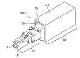
図1は、本発明の実施例1に係る光コネクタ装置100の基本構成をアダプタコネクタ20に対するプラグコネクタ10の装着状態として示したものであり、同図(a)は外観構成の斜視図に関するもの,同図(b)は延在方向で側面断面にした斜視図に関するものである。又、図2は、この光コネクタ装置100の外観構成をアダプタコネクタ20に対するプラグコネクタ10の装着状態で相手側コネクタ40側から示した斜視図である。更に、図3は、この光コネクタ装置100におけるプラグコネクタ10をアダプタコネクタ20内へと変位させた状態を示した外観構成の斜視図である。 FIG. 1 shows a basic configuration of an
この光コネクタ装置100は、所定長の光ファイバ30を保持したフェルール31,32をハウジング11,21により保持して成る基本構造を持つもので、フェルール31,32については、光ファイバ30の両端部をそれぞれ固着した口径φ=1.25mmの接続外径を有する第1のフェルール31と、この第1のフェルールよりも大きな口径φ=2.5mmの接続外径を有する第2のフェルール32とに区別され、ハウジング11,21については、第1のフェルール31を保持すると共に、図示されない接続相手側部品との接続に供される接続部12を有して第1のコネクタとしてのプラグコネクタ10を成すハウジング11と、第2のフェルール32を保持すると共に、同様に接続相手側部品である相手側コネクタ40との接続に供される接続部22を有して第2のコネクタとしてのアダプタコネクタ20を成すハウジング21とに区別される上、プラグコネクタ10が接続相手側部品との嵌合離脱方向でアダプタコネクタ20に対してスライド自在に保持される。因みに、ここでのフェルール31の接続外径は、接続相手側部品に対する接続部12側の形状部分におけるものを示し、フェルール32の接続外径についても、同様に接続相手側部品に対する接続部22側の形状部分におけるものを示している。 The
即ち、この光コネクタ装置100の場合、それぞれ接続外径が異なるフェルール31,32を保持した互いに装着される別体構造によるハウジング11,21がプラグコネクタ10,アダプタコネクタ20を成すと共に、プラグコネクタ10の一部がアダプタコネクタ20の一部に装着挿入された構造であって、しかもプラグコネクタ10と接続される接続相手側部品を接続部12から接続した際、光ファイバ30における第1のフェルール31と第2のフェルール32との間の部分が撓む構造であるため、LC型コネクタ及びSC型コネクタを接続する場合のように異なる径のフェルールを持つ異種コネクタ同士を対象にした場合であっても、特許文献1に係る技術を適用する場合のように光コネクタ用変換スリーブにLC−SC変換アダプタを介在させた上、SC型コネクタとLC型コネクタとの両端アッセンブリーを介して接続するような大規模な組み付けを行う必要がなく、容易に径変換して安定して適確に接続を行うことができる。 In other words, in the case of this
又、この光コネクタ装置100の場合、例えばプラグコネクタ10と接続される接続相手側部品をLC型コネクタとし、アダプタコネクタ20と接続される接続相手側部品をSC型コネクタ(相手側コネクタ40)とした上、SC型コネクタとアダプタコネクタ20とを接続部22側から接続すると共に、LC型コネクタとプラグコネクタ10とを接続部12側から接続した際、図3中の白抜き矢印で示されるようにプラグコネクタ10がアダプタコネクタ20に対してスライド移動して組み付けられ、このときに光ファイバ30におけるフェルール31,32間の部分が撓む構造であるため、特許文献2に係る技術を適用させる場合のように2芯LC型コネクタのインターフェースにおける光軸中心を変位させて2芯並べる煩雑な作業が不要となり、2芯LC型コネクタのインターフェースにおいても簡易に対応できて適確に接続を行うことができる。 Further, in the case of this
尚、実施例1に係る光コネクタ装置100の場合、プラグコネクタ10をスライド可能な構成としたが、これに代えてスライドしないようにアダプタコネクタ20に固定する構造にしても良い。但し、この場合には相手側コネクタ40と接続する際、第1のフェルール31が相手側コネクタ40に押されて移動し、光ファイバ30が撓んで接続することになる。 In the
図4は、本発明の実施例2に係る光コネクタ装置100′におけるプラグコネクタ10′をアダプタコネクタ20′内へと変位させた状態として示した外観構成の斜視図である。又、図5は、この光コネクタ装置100′の細部構造をアダプタコネクタ20′に対するプラグコネクタ10′及び相手側コネクタ40の装着状態で相手側コネクタ40側から斜視方向により示した側面断面図(但し、光ファイバ30は略図している)である。 FIG. 4 is a perspective view of the external configuration of the
この光コネクタ装置100′の場合、先の実施例1に係る光コネクタ装置100にあってのアダプタコネクタ20及びプラグコネクタ10を一部変形した構造とすることにより、プラグコネクタ10が接続相手側部品との嵌合離脱方向でアダプタコネクタ20にスライド自在に保持されるスライド機能を円滑に働かせるための構造を持たせたものである。 In the case of this
具体的に言えば、プラグコネクタ10′については、ハウジング11′における接続部12とは反対側のアダプタコネクタ20′内に挿入されてスライド移動される部分(必要とされる範囲)に対して、外側へ突出し、且つ嵌合離脱方向へ延在する突出部13を並設されるようにし、アダプタコネクタ20′については、同様にハウジング21′における接続部22とは反対側のプラグコネクタ10′が装着されてスライド移動に供する部分(必要とされる範囲)に対して、各突出部13を収容して案内するための嵌合離脱方向へ延在する凹部23を並設されるように持たせた構造としている。 Specifically, the
この光コネクタ装置100′の場合、上述した光コネクタ装置100の場合と同様にLC型コネクタ及びSC型コネクタを対象にしても、容易に径変換して安定して適確に接続を行うことができる他、ここではLC型コネクタとプラグコネクタ10′とを接続部12側から接続したときのプラグコネクタ10′のアダプタコネクタ20′に対するスライド移動が各突出部13に対する各凹部23の案内によって円滑に行われる(必要に応じて位置決めや係止させる構造にすることもできる)ため、先の光コネクタ装置100の場合よりも一層精度良く適確にLC型コネクタを接続できるようになる。 In the case of this
尚、この実施例2に係る光コネクタ装置100′の場合、プラグコネクタ10′がスライド移動するとき、第1のフェルール31については相手側コネクタ40と接続する際、スライド移動する構造、或いはスライド移動しないようにハウジング11′に固定する構造の何れを採用しても良い。 In the case of the
本発明の光コネクタ装置は、LC型コネクタ及びSC型コネクタの接続を行う以外にも、径変換光コネクタ機能を活かすことにより光学測定機器の分野での適用波及にも期待できる。 The optical connector device of the present invention can be expected to spread in the field of optical measuring instruments by making use of the diameter-converting optical connector function in addition to connecting the LC connector and the SC connector.
10,10′ プラグコネクタ
11,11′,21,21′ ハウジング
12,22 接続部
13 突出部
20,20′ アダプタコネクタ
23 凹部
30 光ファイバ
31,32 フェルール
40 相手側コネクタ
100,100′ 光コネクタ装置DESCRIPTION OF
Claims (5)
Translated fromJapanese5. The optical connector device according to claim 1, wherein the first connector is a plug connector, and the second connector is an adapter connector. 6.
Priority Applications (3)
| Application Number | Priority Date | Filing Date | Title |
|---|---|---|---|
| JP2006036982AJP2007219012A (en) | 2006-02-14 | 2006-02-14 | Optical connector device |
| CA002578509ACA2578509A1 (en) | 2006-02-14 | 2007-02-13 | Optical connector apparatus suitable for interconnection between different-diameter ferrules |
| US11/705,630US7329051B2 (en) | 2006-02-14 | 2007-02-13 | Optical connector apparatus suitable for interconnection between different-diameter ferrules |
Applications Claiming Priority (1)
| Application Number | Priority Date | Filing Date | Title |
|---|---|---|---|
| JP2006036982AJP2007219012A (en) | 2006-02-14 | 2006-02-14 | Optical connector device |
Publications (1)
| Publication Number | Publication Date |
|---|---|
| JP2007219012Atrue JP2007219012A (en) | 2007-08-30 |
Family
ID=38369200
Family Applications (1)
| Application Number | Title | Priority Date | Filing Date |
|---|---|---|---|
| JP2006036982APendingJP2007219012A (en) | 2006-02-14 | 2006-02-14 | Optical connector device |
Country Status (3)
| Country | Link |
|---|---|
| US (1) | US7329051B2 (en) |
| JP (1) | JP2007219012A (en) |
| CA (1) | CA2578509A1 (en) |
Cited By (2)
| Publication number | Priority date | Publication date | Assignee | Title |
|---|---|---|---|---|
| JP2010082162A (en)* | 2008-09-30 | 2010-04-15 | Sansei R&D:Kk | Connector unit and game machine |
| KR100955276B1 (en) | 2008-10-22 | 2010-04-30 | 주식회사 골드텔 | Optical connector plug |
Families Citing this family (6)
| Publication number | Priority date | Publication date | Assignee | Title |
|---|---|---|---|---|
| JP2010211024A (en)* | 2009-03-11 | 2010-09-24 | Fujitsu Ltd | Lc adapter |
| US10634854B2 (en) | 2018-01-03 | 2020-04-28 | Afl Ig Llc | Push-pull boot connector for fiber optic cables |
| US12206199B2 (en)* | 2021-01-19 | 2025-01-21 | Reichle & De-Massari Ag | Plug connector device, plug connector and connection cable |
| JP1730736S (en)* | 2022-04-11 | 2022-11-28 | connector | |
| JP1730734S (en)* | 2022-04-11 | 2022-11-28 | connector | |
| JP1730735S (en)* | 2022-04-11 | 2022-11-28 | connector |
Family Cites Families (4)
| Publication number | Priority date | Publication date | Assignee | Title |
|---|---|---|---|---|
| JP3160863B2 (en) | 1991-09-26 | 2001-04-25 | 日本電信電話株式会社 | Optical connection adapter for ferrule diameter conversion |
| US6102581A (en)* | 1998-06-16 | 2000-08-15 | Lucent Technologies Inc. | Optical adapter including a ferrule assembly |
| JP3886312B2 (en) | 2000-01-14 | 2007-02-28 | 株式会社日新化成 | Conversion sleeve for optical connectors |
| US6783281B2 (en)* | 2002-08-13 | 2004-08-31 | Hon Hai Precision Ind. Co., Ltd. | Optical fiber converter retaining different sized ferrules |
- 2006
- 2006-02-14JPJP2006036982Apatent/JP2007219012A/enactivePending
- 2007
- 2007-02-13CACA002578509Apatent/CA2578509A1/ennot_activeAbandoned
- 2007-02-13USUS11/705,630patent/US7329051B2/ennot_activeExpired - Fee Related
Cited By (2)
| Publication number | Priority date | Publication date | Assignee | Title |
|---|---|---|---|---|
| JP2010082162A (en)* | 2008-09-30 | 2010-04-15 | Sansei R&D:Kk | Connector unit and game machine |
| KR100955276B1 (en) | 2008-10-22 | 2010-04-30 | 주식회사 골드텔 | Optical connector plug |
Also Published As
| Publication number | Publication date |
|---|---|
| US20070190834A1 (en) | 2007-08-16 |
| CA2578509A1 (en) | 2007-08-14 |
| US7329051B2 (en) | 2008-02-12 |
Similar Documents
| Publication | Publication Date | Title |
|---|---|---|
| JP2007219012A (en) | Optical connector device | |
| JP5518979B2 (en) | Optical connector receptacle, receptacle housing, optical connector adapter, adapter housing | |
| CN103576248B (en) | Plug and optical connector connector | |
| EP2548062B1 (en) | Fiber optic interface devices for electronic devices | |
| JP2012128341A (en) | Double-core type optical connector | |
| JP4942327B2 (en) | Optical connector | |
| EP3474052B1 (en) | Optical connector and optical connection structure | |
| JP2019028425A (en) | Optical connector plug and double-series optical connector plug | |
| US20100080517A1 (en) | Fiber optic connector assembly employing fiber movement support and method of assembly | |
| CN107111069A (en) | Socket connector and optical coupling construction | |
| CN105051584A (en) | Optical coupler for multicore fiber | |
| EP3467559A1 (en) | Optical connector and optical connection structure | |
| JP2008026647A (en) | Optical receptacle housing, optical connector receptacle and optical device | |
| JP2024075729A (en) | Optical connector manufacturing method | |
| AU2015312152A1 (en) | Optical adaptor for mounting to a receptacle to optically couple connectorized optical cables | |
| WO2014104016A1 (en) | Optical connector apparatus | |
| JP4851430B2 (en) | Optical connector | |
| JP7723109B2 (en) | Optical Connectors and Plugs | |
| CN113740974B (en) | Optical connector and optical connector module thereof | |
| JP2010048925A (en) | Optical cable connector | |
| TWI656368B (en) | Multi-core fiber attenuator | |
| JP5755872B2 (en) | Optical connector and method for manufacturing optical connector with cable | |
| US7416348B2 (en) | Optical connector excellent in assemblability and dimensional accuracy | |
| JP2013257432A (en) | Optical and electric composite connector | |
| JP5508103B2 (en) | Optical cable connector |
Legal Events
| Date | Code | Title | Description |
|---|---|---|---|
| A977 | Report on retrieval | Free format text:JAPANESE INTERMEDIATE CODE: A971007 Effective date:20080911 | |
| A131 | Notification of reasons for refusal | Free format text:JAPANESE INTERMEDIATE CODE: A131 Effective date:20080924 | |
| A02 | Decision of refusal | Free format text:JAPANESE INTERMEDIATE CODE: A02 Effective date:20090204 |