JP2007218403A - Drive transmission mechanism and image forming apparatus having the same - Google Patents
Drive transmission mechanism and image forming apparatus having the sameDownload PDFInfo
- Publication number
- JP2007218403A JP2007218403AJP2006042776AJP2006042776AJP2007218403AJP 2007218403 AJP2007218403 AJP 2007218403AJP 2006042776 AJP2006042776 AJP 2006042776AJP 2006042776 AJP2006042776 AJP 2006042776AJP 2007218403 AJP2007218403 AJP 2007218403A
- Authority
- JP
- Japan
- Prior art keywords
- driven shaft
- shaft
- drive shaft
- coupling member
- drive
- Prior art date
- Legal status (The legal status is an assumption and is not a legal conclusion. Google has not performed a legal analysis and makes no representation as to the accuracy of the status listed.)
- Granted
Links
Images


Classifications
- G—PHYSICS
- G03—PHOTOGRAPHY; CINEMATOGRAPHY; ANALOGOUS TECHNIQUES USING WAVES OTHER THAN OPTICAL WAVES; ELECTROGRAPHY; HOLOGRAPHY
- G03G—ELECTROGRAPHY; ELECTROPHOTOGRAPHY; MAGNETOGRAPHY
- G03G15/00—Apparatus for electrographic processes using a charge pattern
- G03G15/75—Details relating to xerographic drum, band or plate, e.g. replacing, testing
- G03G15/757—Drive mechanisms for photosensitive medium, e.g. gears
- F—MECHANICAL ENGINEERING; LIGHTING; HEATING; WEAPONS; BLASTING
- F16—ENGINEERING ELEMENTS AND UNITS; GENERAL MEASURES FOR PRODUCING AND MAINTAINING EFFECTIVE FUNCTIONING OF MACHINES OR INSTALLATIONS; THERMAL INSULATION IN GENERAL
- F16D—COUPLINGS FOR TRANSMITTING ROTATION; CLUTCHES; BRAKES
- F16D3/00—Yielding couplings, i.e. with means permitting movement between the connected parts during the drive
- F16D3/02—Yielding couplings, i.e. with means permitting movement between the connected parts during the drive adapted to specific functions
- F16D3/04—Yielding couplings, i.e. with means permitting movement between the connected parts during the drive adapted to specific functions specially adapted to allow radial displacement, e.g. Oldham couplings
- G—PHYSICS
- G03—PHOTOGRAPHY; CINEMATOGRAPHY; ANALOGOUS TECHNIQUES USING WAVES OTHER THAN OPTICAL WAVES; ELECTROGRAPHY; HOLOGRAPHY
- G03G—ELECTROGRAPHY; ELECTROPHOTOGRAPHY; MAGNETOGRAPHY
- G03G2221/00—Processes not provided for by group G03G2215/00, e.g. cleaning or residual charge elimination
- G03G2221/16—Mechanical means for facilitating the maintenance of the apparatus, e.g. modular arrangements and complete machine concepts
- G03G2221/1651—Mechanical means for facilitating the maintenance of the apparatus, e.g. modular arrangements and complete machine concepts for connecting the different parts
- G03G2221/1657—Mechanical means for facilitating the maintenance of the apparatus, e.g. modular arrangements and complete machine concepts for connecting the different parts transmitting mechanical drive power
Landscapes
- Engineering & Computer Science (AREA)
- General Engineering & Computer Science (AREA)
- Physics & Mathematics (AREA)
- General Physics & Mathematics (AREA)
- Mechanical Engineering (AREA)
- Electrophotography Configuration And Component (AREA)
Abstract
Translated fromJapaneseDescription
Translated fromJapanese本発明は、駆動軸と被駆動軸を同軸上に接離可能に配置し、一対のカップリング部材を介して該駆動軸の回転駆動力を該被駆動軸に伝達するための駆動伝達機構と、この駆動伝達機構を備えた画像形成装置に関する。 The present invention provides a drive transmission mechanism for disposing a drive shaft and a driven shaft coaxially so as to be able to contact and separate, and transmitting a rotational driving force of the drive shaft to the driven shaft via a pair of coupling members. The present invention also relates to an image forming apparatus provided with this drive transmission mechanism.
高画質化が図られている今日のレーザプリンタやデジタル複写機において、感光体ドラムの回転速度変動が画質に与える影響は大きく、そのため感光体ドラムを回転させるための駆動連結部の構造は、複写機の構造設計における重要な要素となっている。 In today's laser printers and digital copiers, where high image quality has been achieved, fluctuations in the rotational speed of the photosensitive drum have a significant effect on the image quality. Therefore, the structure of the drive connecting part for rotating the photosensitive drum is a copy. It is an important element in the structural design of the machine.
具体的には、4連タンデム方式と呼ばれるカラー複写機等においては、感光体ドラムの回転軸とこれを回転させる駆動軸との偏芯,偏角から発生する,感光体ドラムの1回転当たりの回転速度変動は、印刷用紙に色ずれとなって現れるために大きな問題となる。 Specifically, in a color copying machine called a quadruple tandem system, etc., the rotation per rotation of the photosensitive drum is caused by the eccentricity and deviation of the rotation shaft of the photosensitive drum and the drive shaft that rotates the rotation shaft. The rotational speed fluctuation is a serious problem because it appears as a color shift on the printing paper.
従来、感光体ドラムの回転軸と駆動軸との偏芯や偏角を少なくする方法としては、駆動軸を感光体ドラムに嵌合して位置決めする方法が知られているが、この方法は位置決め調整が極めて困難であるという問題がある。また、正確に位置決めがされたとしても、複写機等は多くの駆動部品を備えているためにこれによって生ずる振動等により経時的に位置ずれが発生することは容易に予想され、困難な位置決め作業が繰り返し必要になるという問題がある。 Conventionally, as a method of reducing the eccentricity and declination between the rotating shaft of the photosensitive drum and the driving shaft, a method of positioning the driving shaft by fitting it to the photosensitive drum is known. There is a problem that adjustment is extremely difficult. Even if the positioning is performed accurately, the copying machine and the like have many driving parts, so that it is easily expected that a positional shift will occur over time due to vibrations caused by this. There is a problem that is necessary repeatedly.
また、駆動軸と被駆動軸とを連結して駆動力を伝達するカップリング機構としては、オルダムカップリングが知られているが、これは偏芯を許容(吸収)することはできても、偏角を許容することができないため、駆動軸と被駆動軸の平行度の精度を上げる必要がある。 In addition, Oldham coupling is known as a coupling mechanism that connects the drive shaft and the driven shaft to transmit the driving force, but this can allow (absorb) eccentricity, Since the deflection angle cannot be allowed, it is necessary to improve the accuracy of the parallelism between the drive shaft and the driven shaft.
そこで、偏芯,偏角を同時に許容するカップリング構造として、駆動軸と被駆動軸のどちらか一方に、半径方向とスラスト方向に自由度(ガタ)を持ってカップリングを装着する駆動伝達装置が提案されている(例えば、特許文献1参照)。 しかしながら、一方の軸だけが偏芯,偏角に応答するために、カップリングにおいてこの軸を保持する部分に大きな負荷が掛かり、カップリングの変形や破損が引き起こされるおそれがある。また、例えば、このカップリングを感光体ドラムを回転するために用いた場合においては、感光体ドラムを清掃,交換のために装置本体から引き出す際および逆に感光体ドラムを装置本体に装着する際のカップリングにおける駆動軸と感光体ドラムの回転軸との連結作業性はあまり良いものではない。
本発明はかかる事情に鑑みてなされたものであり、駆動軸と被駆動軸とを接離容易なカップリングを介して連結させ、しかも一定の偏芯,偏角を許容することができる駆動伝達機構と、この駆動伝達機構を備えた画像形成装置を提供することを目的とする。 The present invention has been made in view of such circumstances, and a drive transmission in which a drive shaft and a driven shaft are coupled via a coupling that is easy to contact and separate, and can allow a certain eccentricity and declination. It is an object of the present invention to provide a mechanism and an image forming apparatus including the drive transmission mechanism.
本発明の請求項1によれば、駆動軸と、該駆動軸の回転により回転する被駆動軸と、該駆動軸の回転駆動力を該被駆動軸に伝達するために該駆動軸と該被駆動軸にそれぞれ取り付けられる一対のカップリング部材とを有する駆動伝達機構であって、前記一対のカップリング部材は、径方向の一方向への首振りと、該一方向と直交する径方向への接触面の滑りとによって、前記駆動軸と前記被駆動軸との偏芯と偏角に起因する前記被駆動軸の回転速度変動を抑制することを特徴とする駆動伝達機構、が提供される。 According to the first aspect of the present invention, the drive shaft, the driven shaft rotated by the rotation of the drive shaft, and the drive shaft and the driven shaft for transmitting the rotational driving force of the drive shaft to the driven shaft. A drive transmission mechanism having a pair of coupling members respectively attached to the drive shaft, wherein the pair of coupling members swings in one radial direction and in a radial direction orthogonal to the one direction. Provided is a drive transmission mechanism characterized by suppressing fluctuations in the rotational speed of the driven shaft caused by eccentricity and declination between the drive shaft and the driven shaft by sliding of the contact surface.
本発明の請求項2によれば、駆動軸と、該駆動軸の回転により回転する被駆動軸と、該駆動軸の回転駆動力を該被駆動軸に伝達するために該駆動軸および該被駆動軸にそれぞれ取り付けられる第1カップリング部材および第2カップリング部材とを有する駆動伝達機構であって、前記第1カップリング部材は、径方向の一方向に設けられた一定幅の凸部と、前記駆動軸を挿通させるための第1挿通孔とを有し、前記第2カップリング部材は、該凸部と嵌合する凹部と、前記被駆動軸を挿通させるための第2挿通孔とを有し、前記第1カップリング部材は、前記凸部の突起長手方向と直交する径方向に首振りするように該径方向に自由度をもって前記駆動軸に装着され、かつ、前記第2カップリング部材は、前記凹部の溝長手方向と直交する径方向に首振りするように該径方向に自由度をもって前記被駆動軸に装着され、前記駆動軸と前記被駆動軸との偏芯と偏角に起因する前記被駆動軸の回転速度変動を、前記第1,第2カップリング部材の首振りと、前記凹部と凸部と接触面での滑りとによって抑制することを特徴とする駆動伝達機構が提供される。 According to
本発明の請求項3によれば、上記請求項2の駆動伝達機構において、前記突起長手方向と直交する径方向において、前記駆動軸の外周と前記第1挿通孔の壁面との間に所定の隙間が設けられ、前記溝長手方向と直交する径方向において、前記被駆動軸の外周と前記第2挿通孔の壁面との間に所定の隙間が設けられている駆動伝達機構が提供される。 According to a third aspect of the present invention, in the drive transmission mechanism according to the second aspect, a predetermined distance is provided between the outer periphery of the drive shaft and the wall surface of the first insertion hole in the radial direction orthogonal to the longitudinal direction of the protrusion. A drive transmission mechanism is provided in which a gap is provided and a predetermined gap is provided between an outer periphery of the driven shaft and a wall surface of the second insertion hole in a radial direction orthogonal to the groove longitudinal direction.
本発明の請求項4によれば、上記請求項2または請求項3の駆動伝達機構において、前記第1カップリング部材の前記突起長手方向での首振りが抑制されるように、該突起長手方向において自由度がない状態で前記駆動軸に装着され、前記第2カップリング部材は、前記溝長手方向での首振りが抑制されるように該溝長手方向において自由度がない状態で前記被駆動軸に装着されている駆動伝達機構が提供される。 According to a fourth aspect of the present invention, in the drive transmission mechanism according to the second or third aspect, the protrusion longitudinal direction of the first coupling member is suppressed so as to be prevented from swinging in the protrusion longitudinal direction. The second coupling member is mounted on the drive shaft in a state where there is no degree of freedom in the longitudinal direction of the groove so that swinging in the longitudinal direction of the groove is suppressed. A drive transmission mechanism mounted on the shaft is provided.
本発明の請求項5によれば、上記請求項2から請求項4の駆動伝達機構において、前記駆動軸は、軸方向と垂直にその先端部に設けられた第1平行ピンと、前記第1カップリング部材をその先端側に押圧するための圧縮バネと、該圧縮バネを保持するための第1保持部とを有し、前記第1カップリング部材は、前記突起長手方向と平行に前記第1平行ピンを収容するための第1ピン収容部を有し、該第1平行ピンを回動軸として首振り動作を行う駆動伝達機構が提供される。 According to a fifth aspect of the present invention, in the drive transmission mechanism according to the second to fourth aspects, the drive shaft includes a first parallel pin provided at a tip portion perpendicular to an axial direction, and the first cup. A compression spring for pressing the ring member toward the distal end thereof; and a first holding portion for holding the compression spring, wherein the first coupling member is parallel to the longitudinal direction of the protrusion. There is provided a drive transmission mechanism that has a first pin accommodating portion for accommodating a parallel pin, and performs a swinging motion with the first parallel pin as a rotation axis.
本発明の請求項6によれば、上記請求項2から請求項5の駆動伝達機構において、前記被駆動軸は、軸方向と垂直にその先端部に設けられた第2平行ピンと、前記第2カップリング部材をその先端で保持するための第2保持部とを有し、前記第2カップリング部材は、前記溝長手方向と平行に前記第2平行ピンを収容するための第2ピン収容部を有し、該第2平行ピンを回動軸として首振り動作を行う駆動伝達機構が提供される。 According to a sixth aspect of the present invention, in the drive transmission mechanism according to the second to fifth aspects, the driven shaft includes a second parallel pin provided at a tip portion perpendicular to the axial direction, and the second A second holding portion for holding the coupling member at its tip, and the second coupling member holds the second parallel pin parallel to the longitudinal direction of the groove. And a drive transmission mechanism that swings around the second parallel pin as a rotation axis.
本発明の請求項7によれば、駆動軸と、該駆動軸の回転により回転する被駆動軸と、該駆動軸の回転駆動力を該被駆動軸に伝達するために該駆動軸と該被駆動軸にそれぞれ取り付けられる一対のカップリング部材とを有する駆動伝達機構と、前記被駆動軸を回転軸とする感光体ドラムとを備えた画像形成装置であって、前記一対のカップリング部材は、径方向の一方向への首振りと、該一方向と垂直な径方向への接触面の滑りとによって、前記駆動軸と前記被駆動軸との偏芯と偏角に起因する前記感光体ドラムの回転速度変動を抑制することを特徴とする画像形成装置が提供される。 According to claim 7 of the present invention, the drive shaft, the driven shaft that rotates by the rotation of the drive shaft, and the drive shaft and the driven shaft for transmitting the rotational driving force of the drive shaft to the driven shaft. An image forming apparatus comprising: a drive transmission mechanism having a pair of coupling members respectively attached to drive shafts; and a photosensitive drum having the driven shaft as a rotation shaft, wherein the pair of coupling members includes: The photosensitive drum caused by eccentricity and declination of the drive shaft and the driven shaft by swinging in one direction in the radial direction and sliding of the contact surface in the radial direction perpendicular to the one direction. An image forming apparatus is provided that suppresses fluctuations in rotational speed.
本発明によれば、駆動軸と被駆動軸の偏芯,偏角を許容(吸収)して、スムーズな回転伝達を行うことができるので、被駆動軸の回転速度変動を極めて小さく抑えることができる。そのため、この駆動伝達機構を電子写真方式を用いたカラー画像形成装置の各色感光体ドラムの回転駆動に適用することにより、色ずれのない綺麗な画像を形成することができる。また、駆動軸と被駆動軸にそれぞれ取り付けられるカップリングは接離容易であるために、例えば、感光体ドラムを装置本体に対して着脱する際の作業も容易に行うことができるという利点がある。 According to the present invention, since the eccentricity and declination of the drive shaft and the driven shaft can be allowed (absorbed) and smooth rotation transmission can be performed, fluctuations in the rotational speed of the driven shaft can be minimized. it can. Therefore, by applying this drive transmission mechanism to the rotational drive of each color photosensitive drum of the color image forming apparatus using the electrophotographic system, it is possible to form a beautiful image without color misregistration. Further, since the couplings attached to the drive shaft and the driven shaft are easy to contact and separate, there is an advantage that, for example, the work when the photosensitive drum is attached to and detached from the apparatus main body can be easily performed. .
以下、本発明の実施の形態について図面を参照しながら詳細に説明する。ここでは、画像形成装置として4連タンデム方式のカラー複写機を例に挙げ、感光体ドラムに駆動伝達機構を適用した場合について説明することとする。 Hereinafter, embodiments of the present invention will be described in detail with reference to the drawings. Here, a four-tandem color copier is taken as an example of the image forming apparatus, and a case where a drive transmission mechanism is applied to the photosensitive drum will be described.
図1に4連タンデム方式カラー複写機1の概略構成図を示す。このカラー複写機1は、上方にスキャナ部2と、胴内排紙部3とを備えている。また、カラー複写機1は、中間転写媒体である中間転写ベルト10と、中間転写ベルト10を張架し、回転させるための駆動ローラ22および従動ローラ23,24と、中間転写ベルト10の下側に沿って並列配置される4組の画像形成部11Y,11M,11C,11BKを備えている。 FIG. 1 shows a schematic configuration diagram of a quadruple tandem color copier 1. The color copying machine 1 includes a
中間転写ベルト10には、耐熱性および耐磨耗性に優れた材料、例えば、半導電性ポリイミドが好適に用いられる。画像形成部11Y,11M,11C,11BKはそれぞれ、イエロー(Y),マゼンタ(M),シアン(C),ブラック(BK)のトナー像を形成するためのものである。画像形成部11Y,11M,11C,11BKはそれぞれ像担持体である感光体ドラム12Y,12M,12C,12BKを有している。中間転写ベルト10は、各画像形成部11C〜11BKの上方において、感光体ドラム12Y〜12BKに接触している。 For the
中間転写ベルト10を挟んで感光体ドラム12Y,12M,12C,12BKと対向する位置(一次転写位置)には、1次転写ローラ20Y,20M,20C,20BKが設けられている。一次転写ローラ20Y〜20BKには+1000V程度の1次転写電圧が印加され、これにより感光体ドラム12Y〜12BK上のトナー像が中間転写ベルト10に一次転写される。
画像形成部11Y,11M,11C,11BKはそれぞれ、感光体ドラム12Y,12M,12C,12BKを個別に帯電させるための帯電チャージャ13Y,13M,13C,13BKと、感光体ドラム12Y,12M,12C,12BK上に形成された潜像にトナーを付着させるための現像ユニット18Y,18M,18C,18BKと、感光体ドラム12Y,12M,12C,12BKをクリーニングするためのクリーニング装置21Y,21M,21C,21BKを備えている。 The
帯電チャージャ13Y〜13BKは、感光体ドラム12Y〜12BK表面を、−700V程度に一様に全面帯電させる。現像ユニット18Y〜18BKは、−500V程度の現像バイアスが印加される現像ローラによりそれぞれイエロー(Y)、マゼンタ(M)、シアン(C)、ブラック(BK)のトナーおよびキャリアからなる二成分現像剤を感光体ドラム12Y〜12BKに供給する。クリーニング装置21Y〜21BKは、クリーニングブレードにより感光体ドラム12Y〜12BKの表面の残留トナーを除去する。 The
画像形成部11Y〜11BKは、カラー複写機1の本体のフロント側(図面手前側)に引き出し可能となっている。そのため、感光体ドラム12Y〜BKと現像ユニット18BK〜18Cの各駆動系は、カラー複写機1の本体のリア側に配置されている。 The
感光体ドラム12Y〜12BKはそれぞれ、回転方向である矢印tの向きに回転しながら、帯電チャージャ13Y〜13BKを通過して現像ユニット18Y〜18BKに至る途中で、レーザ露光装置16によって露光される。この露光のために、カラー複写機1は、スキャナ部2等からの画像データに基づいて、感光体ドラム12Y〜12BK上に潜像を形成するためのレーザ露光装置16を、画像形成部11Y〜11BKの下側に備えている。 Each of the
レーザ露光装置16は、半導体レーザ素子から出射されたレーザビームを、ポリゴンミラー16aにより感光体ドラム12Y〜12BKの軸線方向に走査し、結像レンズ系16b,各ミラー44を経て感光体ドラム12BK〜12C上に結像させる。なお、レーザ露光装置16の各色のレーザビームの出射部にはカバーガラスが設けられる。 The
カラー複写機1では、中間転写ベルト10を回転させるための駆動ローラ22と対向するように、中間転写ベルト10に一次転写されたトナー像を印刷用紙Pに転写(2次転写)するための2次転写ローラ26が配置されている。2次転写ローラ26には+1000V程度の2次転写電圧が印加され、これによって中間転写ベルト10上のトナー像が印刷用紙Pに2次転写される。なお、中間転写ベルト10の2次転写ローラ26の下流には、ベルトクリーナ10aが設けられている。 In the
レーザ露光装置16の下方には、2次転写ローラ26に向けて印刷用紙Pを供給するための第1,第2給紙カセット装置27,28が設けられている。第1,第2給紙カセット装置27,28から2次転写ローラ26に至る間には、第1,第2給紙カセット装置27,28内の印刷用紙Pを取り出すピックアップローラ27a,28aと、分離ローラ27b,28bと、第1,第2搬送ローラ31,32と、レジストローラ33が設けられている。 Below the
また、カラー複写機1の図1右側には手差しにより印刷用紙Pを給紙するための手差しトレイ30が設けられている。手差しトレイ30からレジストローラ33に至る間には、印刷用紙Pを取り出すためのピックアップローラ30aと、手差し給紙ローラ36が設けられている。 Further, a
第1,第2給紙カセット27,28および手差しトレイ30から給紙される印刷用紙Pを垂直方向に搬送する縦搬送路37に沿って、2次転写ローラ26の下流、つまり上側には、印刷用紙Pに転写されたトナー像を熱処理により印刷用紙Pに定着させるための定着装置38が設けられている。 Along the
定着装置38から排紙部3へは排紙搬送路41が設けられており、この排紙搬送路41の終端に排紙ローラ3aが設けられている。カラー複写機1は、排紙部3の図右側に、印刷用紙Pに両面印刷を施すための反転エリア40と、この反転エリア40から印刷用紙Pをレジストローラ33へ戻すための反転搬送ユニット45を備えている。 A paper
排紙ローラ3aは、印刷用紙Pを排紙部3へ送り出す方向の回転(正回転)と、印刷用紙Pを反転搬送ユニット45へ戻す方向の回転(逆回転)とを行うことができるようになっている。反転エリア40はガイド42を備えており、このガイド42は、排紙ローラ3aが印刷用紙Pを反転搬送ユニット45へ戻す方向に回転する際に、印刷用紙Pをガイド41の上側に乗せて、印刷用紙Pを確実に反転搬送ユニット45へ送る。反転搬送ユニット45は、印刷用紙Pを降下搬送するための反転搬送路46と再搬送ローラ47を備えている。 The
次に、感光体ドラム12Y〜12BKを回転させるための機構について説明する。感光体ドラム12Y〜12BKはそれぞれ同じ構造を有しているので、ここでは、感光体ドラム12Yを例に説明することとする。 Next, a mechanism for rotating the
前述の通り、画像形成部11Yは、カラー複写機1の本体のフロント側に引き出し可能であり、感光体ドラム12Yの駆動系(モータ)はカラー複写機1の本体のリア側に配置されているので、感光体ドラム12Yの回転軸(被駆動軸)と、駆動系の回転軸(駆動軸)とは、接離自在である。そのため、感光体ドラム12Yをカラー複写機1の本体に装着した際に、駆動軸の回転を被駆動軸に伝達することができるように、被駆動軸と駆動軸のそれぞれの先端にカップリング部材が取り付けられる。 As described above, the
図2Aに駆動軸の先端に取り付けられる第1カップリング部材の斜視図を、図2Bに被駆動軸の先端に取り付けられる第2カップリング部材の斜視図を、図3Aに第1カップリング部材と第2カップリング部材が嵌合した状態を示す側面図を、図3Bに第1カップリング部材と第2カップリング部材が嵌合した状態を示す別の側面図を、図4Aに図3A中の矢視AA断面図を、図4Bに図3B中の矢視BB断面図を、それぞれ示す。 2A is a perspective view of the first coupling member attached to the tip of the drive shaft, FIG. 2B is a perspective view of the second coupling member attached to the tip of the driven shaft, and FIG. A side view showing a state in which the second coupling member is fitted, another side view showing a state in which the first coupling member and the second coupling member are fitted in FIG. 3B, and FIG. 4A in FIG. An arrow AA sectional view is shown in FIG. 4B, and an arrow BB sectional view in FIG. 3B is shown.
第1カップリング部材50は、径方向の一方向(Y方向とする)に設けられた一定幅(X方向の幅)の凸部51と、駆動軸70を挿通させるための第1挿通孔52を有している。凸部51は正面形状がH型となっているが、これに限定されるものではなく、無垢の突起であってもよい。第1挿通孔52を貫通孔としているので凸部51は2つに分かれているが、径方向の一方向であるY方向に配置されていることに変わりはない。 The
駆動軸70は、軸方向(Z方向)と垂直にその先端部に設けられた第1平行ピン71と、第1カップリング部材50をその先端側に押圧するための圧縮バネ72と、圧縮バネ72を保持するための第1保持部73を有している。 The
このような駆動軸70の先端形状に合わせて、第1カップリング部材50には、凸部51の突起長手方向(Y方向)と平行に、第1平行ピン71を収容するための凹みである第1ピン収容部53が設けられている。 In accordance with the shape of the tip of the
第1カップリング部材50が圧縮バネ72によって駆動軸70の先端側に押圧されることによって、第1平行ピン71が第1ピン収容部53に収容される。駆動軸70を図示しないモータにより回転させると、第1平行ピン71が第1ピン収容部53の壁面に接触した状態で維持されることにより、駆動軸70から第1カップリング部材50へ回転駆動力が伝達されて、第1カップリング部材50が駆動軸70とともに回転する。 When the
図5に駆動軸70の外径と第1挿通孔52の形状との関係を示す。駆動軸70は円柱状であり、したがってその外径dは、径方向で事実上一定とみなされる。第1挿通孔52は、突起長手方向であるY方向には自由度がない状態、つまり駆動軸70に対して第1カップリング部材50がぶれない状態となるような形状とする。このため、第1挿通孔52のY方向径DYは、駆動軸70を挿通させることができる公差範囲、例えば、DY=d+0.1mm程度とすることが好ましい。FIG. 5 shows the relationship between the outer diameter of the
また、第1挿通孔52は、凸部51の突起長手方向と直交する径方向であるX方向には自由度がある状態、つまり駆動軸70に対して第1カップリング部材50に一定のぶれが生ずる形状とする。すなわち、X方向では、駆動軸70の外周と第1挿通孔52の壁面との間に一定の隙間を設けて、首振り動作を生じるようにする。このとき、首振り動作は、第1平行ピン71を回動軸として生じる。 The
そのために、第1挿通孔52のX方向径DXを、例えば、DX=d1+Δとする。ここで、このΔは、必要とされるぶれの大きさを考慮して決定される。例えば、0.2mmの偏芯を許容しようとすれば、Δはこれよりも大きな値、例えば、0.25〜0.3mmとすることができる。For this purpose, the X-direction diameter DX of the
このように、第1カップリング部材50は、凸部51の突起長手方向であるY方向での首振りが抑制されるようにY方向においては自由度がない状態で、かつ、X方向には首振り動作が生じるように所定の自由度をもって、駆動軸70に装着される。 As described above, the
第2カップリング部材60は、凸部51と嵌合する凹部61と、被駆動軸80を挿通させるための第2挿通孔62とを有している。凹部61が凸部51と嵌合する性格上、凹部61の溝長手方向はY方向である。凸部51が凹部61に嵌合された状態において凸部51のX方向での滑り量が少なくなるように、凸部51と凹部61の幅差は、第1カップリング部材50と第2カップリング部材60の製造加工の公差範囲、例えば、0.05mm〜0.2mmとすることが好ましい。第2挿通孔62は、第1挿通孔52と同様に、貫通孔としている。 The
凸部51を凹部61に嵌合させた構造では、オルダムカップリングと同様に、Y方向でこれらの接触面が滑ることによって、偏芯,偏角を吸収することができる。凸部51と凹部61の接触面を滑りやすくするために、第1,第2カップリング部材50,60は、摩擦係数の小さい材料、例えば、ポリアセタール樹脂やフッ素樹脂等が好適に用いられる。 In the structure in which the
被駆動軸80は、軸方向(Z方向)と垂直にその先端部に設けられた第2平行ピン81と、第2カップリング部材60をその先端で保持するための第2保持部82とを有している。第2平行ピン81の軸方向はY方向となっている。 The driven
第2保持部82は、第2カップリング部材60が感光体ドラム12Y側へ押し込まれるのを防止している。なお、感光体ドラム12Yのカラー複写機1の本体への装着時には、第1カップリング部材50が圧縮バネ72によってスラスト方向に荷重を加えているので、凸部51と凹部61とが嵌合せずに、凹部61の上面が凸部50の上面に接触し、第1カップリング部材50が第2カップリング部材60に押されてZ方向(図示しないモータ側)に移動することがある。その場合でも、この状態で、駆動軸70または被駆動軸80を一定角度回転させれば、容易に、凸部51と凹部61とを嵌合させることができる。このように、第1,第2カップリング部材50は、感光体ドラム12Yの着脱を容易とする構造となっている。 The
被駆動軸80の先端形状に合わせて、第2カップリング部材60は、溝長手方向(Y方向)と平行に第2平行ピン81を収容するための第2ピン収容部63を備えている。第1カップリング部材50の凸部51を第2カップリング部材60の凹部61に嵌合させた状態で駆動軸70を回転させると、第1カップリング部材50の回転が、凸部51と凹部61の嵌合によって第2カップリング部材60に伝達される。第2カップリング部材60が回転すると、第2ピン収容部63の壁面が第2平行ピン81を回転させて被駆動軸80を回転させる。これにより、感光体ドラム12Yが回転する。 In accordance with the tip shape of the driven
第2カップリング部材60は、第1カップリング部材50と同様にして、凹部61の溝長手方向であるY方向での首振りが抑制されるように、Y方向においては自由度がない状態で、かつ、X方向には首振り動作が生じるように所定の自由度をもって、被駆動軸80に装着される。そのため、第2挿通孔62の形状は第1挿通孔52と同様に設計される。なお、第2カップリング部材60の首振り動作では、第2平行ピン81が回動軸となる。 In the same manner as the
上述の通り、第1カップリング部材50と第2カップリング部材60とを嵌合させて駆動軸70から被駆動軸80へ駆動伝達を行う場合に、連結される駆動軸70と被駆動軸80に偏芯,偏角が生じた場合でも、X方向では第1,第2カップリング部材50,60の首振り動作により、また前述の通り、Y方向では第1,第2カップリング部材50,60どうしの接触面の滑り動作により、偏芯,偏角を吸収することができるので、被駆動軸80に回転速度変動が発生することを抑制することができる。 As described above, when driving transmission is performed from the
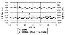
図6に、ともに直径dがφ8mmの駆動軸70と被駆動軸80とを0.25mm偏芯させて配置し、これらをともにDXがφ8.3mm,DYがφ8.1mmの第1,第2カップリング部材50,60を用いて連結させ、駆動軸70と被駆動軸80の回転速度をエンコーダ同時測定し、速度変動を印刷用紙に形成される画像上でのずれに換算したときの変動を示す。また図7には、径方向の一方向に滑りを生じさせるオルダムカップリングを用いて、同様に測定した変動を示す。6, both the diameter d is arranged to be 0.25mm eccentric and driven
これら図6と図7を比較すると明らかなように、従来のオルダムカップリングでは被駆動軸の偏芯を許容することができず、1回転周期で被駆動軸80の速度が大きく変動していることが分かる。これに対して、上述の第1,第2カップリング部材50,60を用いることにより、駆動軸70と被駆動軸80に偏芯が生じても、速度変動を起こすことなく駆動伝達が行われていることが確認された。 As is clear from comparison between FIGS. 6 and 7, the conventional Oldham coupling cannot tolerate the eccentricity of the driven shaft, and the speed of the driven
本発明は上述した実施の形態に限定されることなく、特許請求の範囲に記載した発明の範囲内で種々の変形が可能であり、それらも本発明の範囲内に含まれるものであることは言うまでもない。 The present invention is not limited to the above-described embodiment, and various modifications are possible within the scope of the invention described in the claims, and these are also included in the scope of the present invention. Needless to say.
1…カラー複写機、11Y・11M・11C・11BK…画像形成部、12Y・12M・12C・12BK…感光体ドラム、50…第1カップリング部材、51…凸部、52…第1挿通孔、53…第1ピン収容部、60…第2カップリング部材、61…凹部、62…第2挿通孔、63…第2ピン収容部、70…駆動軸、71…第1平行ピン、72…圧縮バネ、80…被駆動軸、81…第2平行ピン。 DESCRIPTION OF SYMBOLS 1 ... Color copier, 11Y * 11M * 11C * 11BK ... Image forming part, 12Y * 12M * 12C * 12BK ... Photosensitive drum, 50 ... First coupling member, 51 ... Convex part, 52 ... First insertion hole, 53 ... 1st pin accommodating part, 60 ... 2nd coupling member, 61 ... Recessed part, 62 ... 2nd penetration hole, 63 ... 2nd pin accommodating part, 70 ... Drive shaft, 71 ... 1st parallel pin, 72 ... Compression Spring, 80 ... driven shaft, 81 ... second parallel pin.
Claims (7)
Translated fromJapanese前記一対のカップリング部材は、径方向の一方向への首振りと、該一方向と直交する径方向への接触面の滑りとによって、前記駆動軸と前記被駆動軸との偏芯と偏角に起因する前記被駆動軸の回転速度変動を抑制することを特徴とする駆動伝達機構。A drive shaft, a driven shaft that rotates by rotation of the drive shaft, and a pair of couplings that are respectively attached to the drive shaft and the driven shaft to transmit the rotational driving force of the drive shaft to the driven shaft A drive transmission mechanism having a member,
The pair of coupling members are arranged so that the drive shaft and the driven shaft are decentered and deviated by swinging in one radial direction and sliding the contact surface in the radial direction perpendicular to the one direction. A drive transmission mechanism that suppresses fluctuations in rotational speed of the driven shaft caused by an angle.
前記第1カップリング部材は、径方向の一方向に設けられた一定幅の凸部と、前記駆動軸を挿通させるための第1挿通孔とを有し、
前記第2カップリング部材は、該凸部と嵌合する凹部と、前記被駆動軸を挿通させるための第2挿通孔とを有し、
前記第1カップリング部材は、前記凸部の突起長手方向と直交する径方向に首振りするように該径方向に自由度をもって前記駆動軸に装着され、かつ、前記第2カップリング部材は、前記凹部の溝長手方向と直交する径方向に首振りするように該径方向に自由度をもって前記被駆動軸に装着され、
前記駆動軸と前記被駆動軸との偏芯と偏角に起因する前記被駆動軸の回転速度変動を、前記第1,第2カップリング部材の首振りと、前記凹部と凸部と接触面での滑りとによって抑制することを特徴とする駆動伝達機構。A drive shaft, a driven shaft that rotates by rotation of the drive shaft, and a first coupling that is attached to the drive shaft and the driven shaft, respectively, for transmitting the rotational driving force of the drive shaft to the driven shaft A drive transmission mechanism having a member and a second coupling member,
The first coupling member has a convex portion having a constant width provided in one radial direction, and a first insertion hole for inserting the drive shaft,
The second coupling member has a concave portion that fits the convex portion, and a second insertion hole through which the driven shaft is inserted,
The first coupling member is attached to the drive shaft with a degree of freedom in the radial direction so as to swing in the radial direction orthogonal to the protrusion longitudinal direction of the convex portion, and the second coupling member is It is mounted on the driven shaft with a degree of freedom in the radial direction so as to swing in the radial direction perpendicular to the groove longitudinal direction of the recess,
The fluctuations in the rotational speed of the driven shaft caused by the eccentricity and declination of the driving shaft and the driven shaft are caused by the swinging of the first and second coupling members, the concave portion, the convex portion, and the contact surface. A drive transmission mechanism characterized by being suppressed by slippage in
前記溝長手方向と直交する径方向において、前記被駆動軸の外周と前記第2挿通孔の壁面との間に所定の隙間が設けられていることを特徴とする請求項2に記載の駆動伝達機構。In the radial direction perpendicular to the protrusion longitudinal direction, a predetermined gap is provided between the outer periphery of the drive shaft and the wall surface of the first insertion hole,
The drive transmission according to claim 2, wherein a predetermined gap is provided between an outer periphery of the driven shaft and a wall surface of the second insertion hole in a radial direction orthogonal to the groove longitudinal direction. mechanism.
前記第1カップリング部材は、前記突起長手方向と平行に前記第1平行ピンを収容するための第1ピン収容部を有し、該第1平行ピンを回動軸として首振り動作を行うことを特徴とする請求項2から請求項4のいずれか1項に記載の駆動伝達機構。The drive shaft includes a first parallel pin provided at a tip thereof perpendicular to the axial direction, a compression spring for pressing the first coupling member toward the tip, and a first spring for holding the compression spring. 1 holding part,
The first coupling member has a first pin accommodating portion for accommodating the first parallel pin parallel to the longitudinal direction of the protrusion, and performs a swinging motion with the first parallel pin as a rotation axis. The drive transmission mechanism according to any one of claims 2 to 4, wherein:
前記第2カップリング部材は、前記溝長手方向と平行に前記第2平行ピンを収容するための第2ピン収容部を有し、該第2平行ピンを回動軸として首振り動作を行うことを特徴とする請求項2から請求項5のいずれか1項に記載の駆動伝達機構。The driven shaft has a second parallel pin provided at the tip thereof perpendicular to the axial direction, and a second holding portion for holding the second coupling member at the tip,
The second coupling member has a second pin housing portion for housing the second parallel pin in parallel with the longitudinal direction of the groove, and swings around the second parallel pin as a rotation shaft. The drive transmission mechanism according to any one of claims 2 to 5, wherein:
前記被駆動軸を回転軸とする感光体ドラムとを備えた画像形成装置であって、
前記一対のカップリング部材は、径方向の一方向への首振りと、該一方向と垂直な径方向への接触面の滑りとによって、前記駆動軸と前記被駆動軸との偏芯と偏角に起因する前記感光体ドラムの回転速度変動を抑制することを特徴とする画像形成装置。A drive shaft, a driven shaft that rotates by rotation of the drive shaft, and a pair of couplings that are respectively attached to the drive shaft and the driven shaft to transmit the rotational driving force of the drive shaft to the driven shaft A drive transmission mechanism having a member;
An image forming apparatus including a photosensitive drum having the driven shaft as a rotation shaft,
The pair of coupling members are configured so that the drive shaft and the driven shaft are decentered and deviated by swinging in one radial direction and sliding the contact surface in the radial direction perpendicular to the one direction. An image forming apparatus, wherein fluctuations in rotation speed of the photosensitive drum due to corners are suppressed.
Priority Applications (3)
| Application Number | Priority Date | Filing Date | Title |
|---|---|---|---|
| JP2006042776AJP4758247B2 (en) | 2006-02-20 | 2006-02-20 | Drive transmission mechanism and image forming apparatus having the same |
| US11/676,572US7623811B2 (en) | 2006-02-20 | 2007-02-20 | Drive transmitting mechanism and image forming apparatus |
| US12/574,366US7945192B2 (en) | 2006-02-20 | 2009-10-06 | Drive transmitting mechanism for an image forming apparatus |
Applications Claiming Priority (1)
| Application Number | Priority Date | Filing Date | Title |
|---|---|---|---|
| JP2006042776AJP4758247B2 (en) | 2006-02-20 | 2006-02-20 | Drive transmission mechanism and image forming apparatus having the same |
Publications (2)
| Publication Number | Publication Date |
|---|---|
| JP2007218403Atrue JP2007218403A (en) | 2007-08-30 |
| JP4758247B2 JP4758247B2 (en) | 2011-08-24 |
Family
ID=38428312
Family Applications (1)
| Application Number | Title | Priority Date | Filing Date |
|---|---|---|---|
| JP2006042776AExpired - Fee RelatedJP4758247B2 (en) | 2006-02-20 | 2006-02-20 | Drive transmission mechanism and image forming apparatus having the same |
Country Status (2)
| Country | Link |
|---|---|
| US (2) | US7623811B2 (en) |
| JP (1) | JP4758247B2 (en) |
Cited By (11)
| Publication number | Priority date | Publication date | Assignee | Title |
|---|---|---|---|---|
| JP2009205148A (en)* | 2008-02-01 | 2009-09-10 | Konica Minolta Business Technologies Inc | Electrophotographic photoreceptor and image forming method |
| JP2009258500A (en)* | 2008-04-18 | 2009-11-05 | Canon Finetech Inc | Drive transmission mechanism and image forming apparatus using the same |
| US8275286B2 (en) | 2006-12-22 | 2012-09-25 | Canon Kabushiki Kaisha | Process cartridge, electrophotographic image forming apparatus, and electrophotographic photosensitive drum unit |
| US8295734B2 (en) | 2006-12-22 | 2012-10-23 | Canon Kabushiki Kaisha | Rotational force transmitting parts |
| US8346125B2 (en) | 2008-12-08 | 2013-01-01 | Brother Kogyo Kabushiki Kaisha | Process cartridge and developing cartridge |
| US8437669B2 (en) | 2007-03-23 | 2013-05-07 | Canon Kabushiki Kaisha | Electrophotographic image forming apparatus, developing apparatus, and coupling member |
| JP2014197158A (en)* | 2012-05-30 | 2014-10-16 | 三菱化学株式会社 | Bearing member, end portion member, photoreceptor drum unit, process cartridge, and manufacturing method of bearing member |
| US9477201B2 (en) | 2008-06-20 | 2016-10-25 | Canon Kabushiki Kaisha | Cartridge, mounting method for coupling member, and disassembling method for coupling member |
| JP2017187111A (en)* | 2016-04-06 | 2017-10-12 | キヤノン株式会社 | Drive transmission device and image formation device |
| JP2017207565A (en)* | 2016-05-17 | 2017-11-24 | 株式会社リコー | Rotation driving device and image forming apparatus |
| JP2020085230A (en)* | 2018-11-30 | 2020-06-04 | 東友科技股▲ふん▼有限公司 | Clutch claw and clutch structure using same |
Families Citing this family (12)
| Publication number | Priority date | Publication date | Assignee | Title |
|---|---|---|---|---|
| JP5127584B2 (en) | 2008-06-20 | 2013-01-23 | キヤノン株式会社 | Drum unit and electrophotographic image forming apparatus |
| JP5506236B2 (en) | 2009-04-30 | 2014-05-28 | キヤノン株式会社 | Cartridge and electrophotographic image forming apparatus |
| JP5029664B2 (en)* | 2009-09-09 | 2012-09-19 | ブラザー工業株式会社 | Image forming apparatus and cartridge |
| CN103392074A (en)* | 2010-12-07 | 2013-11-13 | 易赛迪许克斯瓦根有限责任公司 | Coupling, rotor, and assembly for a pump |
| WO2013006996A1 (en)* | 2011-07-13 | 2013-01-17 | 江西亿铂电子科技有限公司 | Photosensitive drum and processing box |
| KR101939291B1 (en)* | 2012-08-27 | 2019-01-16 | 엘지전자 주식회사 | Washing Machine |
| JP5877174B2 (en)* | 2013-04-25 | 2016-03-02 | 株式会社沖データ | Driving force transmission device, medium conveying device, image reading device, and image forming device |
| CN103322075A (en)* | 2013-06-04 | 2013-09-25 | 镇江苏冶传动科技有限公司 | Suspended elastic pin gear type coupling |
| KR20150051068A (en)* | 2013-11-01 | 2015-05-11 | 삼성전자주식회사 | Power transmitting device and image forming apparatus having the same |
| US9829855B2 (en)* | 2014-05-22 | 2017-11-28 | Lexmark International, Inc. | Drive coupler |
| CN210109559U (en)* | 2018-08-20 | 2020-02-21 | 纳思达股份有限公司 | Power receiving member and process cartridge |
| CN111252587B (en)* | 2018-11-30 | 2021-07-09 | 东友科技股份有限公司 | Separating claw and its applicable clutch structure |
Citations (1)
| Publication number | Priority date | Publication date | Assignee | Title |
|---|---|---|---|---|
| JP2002098162A (en)* | 2000-09-22 | 2002-04-05 | Nippon Piston Ring Co Ltd | Oldham coupling |
Family Cites Families (6)
| Publication number | Priority date | Publication date | Assignee | Title |
|---|---|---|---|---|
| JP3825155B2 (en)* | 1997-01-16 | 2006-09-20 | 東北リコー株式会社 | Stencil printing machine |
| JP4046933B2 (en)* | 2000-08-02 | 2008-02-13 | キヤノン株式会社 | Drive transmission device and image forming apparatus having the same |
| US6829455B2 (en)* | 2000-10-20 | 2004-12-07 | Canon Kabushiki Kaisha | Driving force transmission mechanism, image forming apparatus equipped with such a mechanism, and process unit of such an apparatus |
| JP2005156654A (en)* | 2003-11-21 | 2005-06-16 | Canon Inc | Charging device, process cartridge, and image forming apparatus |
| JP3885074B2 (en)* | 2004-05-11 | 2007-02-21 | キヤノン株式会社 | Electrophotographic photosensitive drum, process cartridge, and electrophotographic image forming apparatus |
| JP4710476B2 (en)* | 2004-10-28 | 2011-06-29 | ブラザー工業株式会社 | Image forming apparatus |
- 2006
- 2006-02-20JPJP2006042776Apatent/JP4758247B2/ennot_activeExpired - Fee Related
- 2007
- 2007-02-20USUS11/676,572patent/US7623811B2/enactiveActive
- 2009
- 2009-10-06USUS12/574,366patent/US7945192B2/ennot_activeExpired - Fee Related
Patent Citations (1)
| Publication number | Priority date | Publication date | Assignee | Title |
|---|---|---|---|---|
| JP2002098162A (en)* | 2000-09-22 | 2002-04-05 | Nippon Piston Ring Co Ltd | Oldham coupling |
Cited By (72)
| Publication number | Priority date | Publication date | Assignee | Title |
|---|---|---|---|---|
| US9864331B2 (en) | 2006-12-22 | 2018-01-09 | Canon Kabushiki Kaisha | Process cartridge, electrophotographic image forming apparatus, and electrophotographic photosensitive drum unit |
| US9869960B2 (en) | 2006-12-22 | 2018-01-16 | Canon Kabushiki Kaisha | Process cartridge, electrophotographic image forming apparatus, and electrophotographic photosensitive drum unit |
| US12405567B2 (en) | 2006-12-22 | 2025-09-02 | Canon Kabushiki Kaisha | Process cartridge, electrophotographic image forming apparatus, and electrophotographic photosensitive drum unit |
| US8275286B2 (en) | 2006-12-22 | 2012-09-25 | Canon Kabushiki Kaisha | Process cartridge, electrophotographic image forming apparatus, and electrophotographic photosensitive drum unit |
| US8280278B2 (en) | 2006-12-22 | 2012-10-02 | Canon Kabushiki Kaisha | Process cartridge, electrophotographic image forming apparatus, and electrophotographic photosensitive drum unit |
| US8295734B2 (en) | 2006-12-22 | 2012-10-23 | Canon Kabushiki Kaisha | Rotational force transmitting parts |
| US11720054B2 (en) | 2006-12-22 | 2023-08-08 | Canon Kabushiki Kaisha | Process cartridge, electrophotographic image forming apparatus, and electrophotographic photosensitive drum unit |
| US11237517B2 (en) | 2006-12-22 | 2022-02-01 | Canon Kabushiki Kaisha | Process cartridge, electrophotographic image forming apparatus, and electrophotographic photosensitive drum unit |
| US9857764B2 (en) | 2006-12-22 | 2018-01-02 | Canon Kabushiki Kaisha | Process cartridge, electrophotographic image forming apparatus, and electrophotographic photosensitive drum unit |
| US8532533B2 (en) | 2006-12-22 | 2013-09-10 | Canon Kabushiki Kaisha | Rotational force transmitting part |
| US8630564B2 (en) | 2006-12-22 | 2014-01-14 | Canon Kabushiki Kaisha | Process cartridge electrophotographic image forming apparatus, and electrophotographic photosensitive drum unit |
| US11156956B2 (en) | 2006-12-22 | 2021-10-26 | Canon Kabushiki Kaisha | Rotational force transmitting part |
| US9176468B2 (en) | 2006-12-22 | 2015-11-03 | Canon Kabushiki Kaisha | Rotational force transmitting part |
| US10877433B2 (en) | 2006-12-22 | 2020-12-29 | Canon Kabushiki Kaisha | Process cartridge, electrophotographic image forming apparatus, and electrophotographic photosensitive drum unit |
| US10845756B2 (en) | 2006-12-22 | 2020-11-24 | Canon Kabushiki Kaisha | Rotational force transmitting part |
| US9678471B2 (en) | 2006-12-22 | 2017-06-13 | Canon Kabushiki Kaisha | Process cartridge, electrophotographic image forming apparatus, and electrophotographic photosensitive drum unit |
| US10671018B2 (en) | 2006-12-22 | 2020-06-02 | Canon Kabushiki Kaisha | Process cartridge, electrophotographic image forming apparatus, and electrophotographic photosensitive drum unit |
| US9733614B2 (en) | 2006-12-22 | 2017-08-15 | Canon Kabushiki Kaisha | Process cartridge, electrophotographic image forming apparatus, and electrophotographic photosensitive drum unit |
| US9746826B2 (en) | 2006-12-22 | 2017-08-29 | Canon Kabushiki Kaisha | Process cartridge, electrophotographic image forming apparatus, and electrophotographic photosensitive drum unit |
| US9772602B2 (en) | 2006-12-22 | 2017-09-26 | Canon Kabushiki Kaisha | Rotational force transmitting part |
| US10585391B2 (en) | 2006-12-22 | 2020-03-10 | Canon Kabushiki Kaisha | Process cartridge, electrophotographic image forming apparatus, and electrophotographic photosensitive drum unit |
| US10551793B2 (en) | 2006-12-22 | 2020-02-04 | Canon Kabushiki Kaisha | Process cartridge, electrophotographic image forming apparatus, and electrophotographic photosensitive drum unit |
| US10539923B2 (en) | 2006-12-22 | 2020-01-21 | Canon Kabushiki Kaisha | Process cartridge, electrophotographic image forming apparatus, and electrophotographic photosensitive drum unit |
| US9836021B2 (en) | 2006-12-22 | 2017-12-05 | Canon Kabushiki Kaisha | Process cartridge, electrophotographic image forming apparatus, and electrophotographic photosensitive drum unit |
| US10539924B2 (en) | 2006-12-22 | 2020-01-21 | Canon Kabushiki Kaisha | Process cartridge, electrophotographic image forming apparatus, and electrophotographic photosensitive drum unit |
| US10429794B2 (en) | 2006-12-22 | 2019-10-01 | Canon Kabushiki Kaisha | Rotational force transmitting part |
| US9841727B2 (en) | 2006-12-22 | 2017-12-12 | Canon Kabushiki Kaisha | Process cartridge, electrophotographic image forming apparatus, and electrophotographic photosensitive drum unit |
| US9841728B2 (en) | 2006-12-22 | 2017-12-12 | Canon Kabushiki Kaisha | Process cartridge having changeable relative positioning of a coupling member and another part of the process cartridge |
| US9841729B2 (en) | 2006-12-22 | 2017-12-12 | Canon Kabushiki Kaisha | Process cartridge, electrophotographic image forming apparatus, and electrophotographic photosensitive drum unit |
| US9846408B2 (en) | 2006-12-22 | 2017-12-19 | Canon Kabushiki Kaisha | Process cartridge, electrophotographic image forming apparatus, and electrophotographic photosensitive drum unit |
| US10209670B2 (en) | 2006-12-22 | 2019-02-19 | Canon Kabushiki Kaisha | Rotational force transmitting part |
| US9874846B2 (en) | 2006-12-22 | 2018-01-23 | Canon Kabushiki Kaisha | Process cartridge, electrophotographic image forming apparatus, and electrophotographic photosensitive drum unit |
| US9874854B2 (en) | 2006-12-22 | 2018-01-23 | Canon Kabushiki Kaisha | Process cartridge, electrophotographic image forming apparatus, and electrophotographic photosensitive drum unit |
| US9857765B2 (en) | 2006-12-22 | 2018-01-02 | Canon Kabushiki Kaisha | Process cartridge, electrophotographic image forming apparatus, and electrophotographic photosensitive drum unit |
| US8452210B2 (en) | 2006-12-22 | 2013-05-28 | Canon Kabushiki Kaisha | Rotational force transmitting part |
| US9864333B2 (en) | 2006-12-22 | 2018-01-09 | Canon Kabushiki Kaisha | Process cartridge, electrophotographic image forming apparatus, and electrophotographic photosensitive drum unit |
| US10712710B2 (en) | 2007-03-23 | 2020-07-14 | Canon Kabushiki Kaisha | Electrophotographic image forming apparatus, developing apparatus, and coupling member |
| US9841724B2 (en) | 2007-03-23 | 2017-12-12 | Canon Kabushiki Kaisha | Image forming apparatus cartridge having changeable relative positioning of a coupling member and another part of the image forming apparatus cartridge |
| US9857766B2 (en) | 2007-03-23 | 2018-01-02 | Canon Kabushiki Kaisha | Electrophotographic image forming apparatus, developing apparatus, and coupling member |
| US9851688B2 (en) | 2007-03-23 | 2017-12-26 | Canon Kabushiki Kaisha | Electrophotographic image forming apparatus, developing apparatus, and coupling member |
| US10712709B2 (en) | 2007-03-23 | 2020-07-14 | Canon Kabushiki Kaisha | Electrophotographic image forming apparatus, developing apparatus, and coupling member |
| US9939776B2 (en) | 2007-03-23 | 2018-04-10 | Canon Kabushiki Kaisha | Electrophotographic image forming apparatus, developing apparatus, and coupling member |
| US10795312B2 (en) | 2007-03-23 | 2020-10-06 | Canon Kabushiki Kaisha | Electrophotographic image forming apparatus, developing apparatus, and coupling member |
| US9851685B2 (en) | 2007-03-23 | 2017-12-26 | Canon Kabushiki Kaisha | Electrophotographic image forming apparatus, developing apparatus, and coupling member |
| US10788790B2 (en) | 2007-03-23 | 2020-09-29 | Canon Kabushiki Kaisha | Electrophotographic image forming apparatus, developing apparatus, and coupling member |
| US10520887B2 (en) | 2007-03-23 | 2019-12-31 | Canon Kabushiki Kaisha | Electrophotographic image forming apparatus, developing apparatus, and coupling member |
| US9836015B2 (en) | 2007-03-23 | 2017-12-05 | Canon Kabushiki Kaisha | Electrophotographic image forming apparatus, developing apparatus, and coupling member |
| US12298704B2 (en) | 2007-03-23 | 2025-05-13 | Canon Kabushiki Kaisha | Electrophotographic image forming apparatus, developing apparatus, and coupling member |
| US11675308B2 (en) | 2007-03-23 | 2023-06-13 | Canon Kabushiki Kaisha | Electrophotographic image forming apparatus, developing apparatus, and coupling member |
| US9817333B2 (en) | 2007-03-23 | 2017-11-14 | Canon Kabushiki Kaisha | Electrophotographic image forming apparatus, developing apparatus, and coupling member |
| US8437669B2 (en) | 2007-03-23 | 2013-05-07 | Canon Kabushiki Kaisha | Electrophotographic image forming apparatus, developing apparatus, and coupling member |
| US10620582B2 (en) | 2007-03-23 | 2020-04-14 | Canon Kabushiki Kaisha | Electrophotographic image forming apparatus, developing apparatus, and coupling member |
| US10816931B2 (en) | 2007-03-23 | 2020-10-27 | Canon Kabushiki Kaisha | Electrophotographic image forming apparatus, developing apparatus, and coupling member |
| US9703257B2 (en) | 2007-03-23 | 2017-07-11 | Canon Kabushiki Kaisha | Electrophotographic image forming apparatus, developing apparatus, and coupling member |
| US11204584B2 (en) | 2007-03-23 | 2021-12-21 | Canon Kabushiki Kaisha | Electrophotographic image forming apparatus, developing apparatus, and coupling member |
| US9886002B2 (en) | 2007-03-23 | 2018-02-06 | Canon Kabushiki Kaisha | Electrophotographic image forming apparatus, developing apparatus, and coupling member |
| US10788789B2 (en) | 2007-03-23 | 2020-09-29 | Canon Kabushiki Kaisha | Electrophotographic image forming apparatus, developing apparatus, and coupling member |
| JP2009205148A (en)* | 2008-02-01 | 2009-09-10 | Konica Minolta Business Technologies Inc | Electrophotographic photoreceptor and image forming method |
| US8029955B2 (en) | 2008-02-01 | 2011-10-04 | Konica Minolta Business Technologies, Inc. | Electrophotographic photoreceptor and image forming method |
| JP2009258500A (en)* | 2008-04-18 | 2009-11-05 | Canon Finetech Inc | Drive transmission mechanism and image forming apparatus using the same |
| US9594343B2 (en) | 2008-06-20 | 2017-03-14 | Canon Kabushiki Kaisha | Cartridge, mounting method for coupling member, and disassembling method for coupling member |
| US9477201B2 (en) | 2008-06-20 | 2016-10-25 | Canon Kabushiki Kaisha | Cartridge, mounting method for coupling member, and disassembling method for coupling member |
| US10901360B2 (en) | 2008-06-20 | 2021-01-26 | Canon Kabushiki Kaisha | Cartridge, mounting method for coupling member, and disassembling method for coupling member |
| US11209772B2 (en) | 2008-06-20 | 2021-12-28 | Canon Kabushiki Kaisha | Cartridge, mounting method for coupling member, and disassemblying method for coupling member |
| US10545450B2 (en) | 2008-06-20 | 2020-01-28 | Canon Kabushiki Kaisha | Cartridge, mounting method for coupling member, and disassembling method for coupling member |
| US10095179B2 (en) | 2008-06-20 | 2018-10-09 | Canon Kabushiki Kaisha | Cartridge, mounting method for coupling member, and disassembling method for coupling member |
| US8346125B2 (en) | 2008-12-08 | 2013-01-01 | Brother Kogyo Kabushiki Kaisha | Process cartridge and developing cartridge |
| JP2014197158A (en)* | 2012-05-30 | 2014-10-16 | 三菱化学株式会社 | Bearing member, end portion member, photoreceptor drum unit, process cartridge, and manufacturing method of bearing member |
| JP2017187111A (en)* | 2016-04-06 | 2017-10-12 | キヤノン株式会社 | Drive transmission device and image formation device |
| JP2017207565A (en)* | 2016-05-17 | 2017-11-24 | 株式会社リコー | Rotation driving device and image forming apparatus |
| US10914346B2 (en) | 2018-11-30 | 2021-02-09 | Teco Image Systems Co., Ltd. | Clutch claw and clutch structure using same |
| JP2020085230A (en)* | 2018-11-30 | 2020-06-04 | 東友科技股▲ふん▼有限公司 | Clutch claw and clutch structure using same |
Also Published As
| Publication number | Publication date |
|---|---|
| US7945192B2 (en) | 2011-05-17 |
| US7623811B2 (en) | 2009-11-24 |
| US20100021207A1 (en) | 2010-01-28 |
| JP4758247B2 (en) | 2011-08-24 |
| US20070196131A1 (en) | 2007-08-23 |
Similar Documents
| Publication | Publication Date | Title |
|---|---|---|
| JP4758247B2 (en) | Drive transmission mechanism and image forming apparatus having the same | |
| US9772599B2 (en) | Driving force transmission unit and image forming apparatus including same | |
| US10656565B2 (en) | Drive transmission device and image forming apparatus incorporating the drive transmission device | |
| US8204400B2 (en) | Charging device capable of efficiently charging image carrier | |
| US20110170892A1 (en) | Drive transmission device and image forming apparatus including same | |
| US9494906B2 (en) | Driving force transmission device and image forming apparatus using the same | |
| JP2006139230A (en) | Image forming apparatus | |
| US9109633B2 (en) | Driving force transmission mechanism and image forming apparatus | |
| JP2014044276A (en) | Drive transmission apparatus and image forming device | |
| CN101556446B (en) | Rotational drive transmission mechanism and image forming apparatus using the same | |
| US9042786B2 (en) | Rotation driving force transmitting member, photoreceptor drum, process cartridge, and image forming apparatus | |
| JP4658709B2 (en) | Process cartridge and image forming apparatus | |
| US11579560B2 (en) | Driving force transmission mechanism and image forming apparatus | |
| JP2010133476A (en) | Shaft coupling structure, unit for image forming device using the same, and image forming device using the unit | |
| JP2008069914A (en) | Shaft coupling and image forming device equipped therewith | |
| JP2008233329A (en) | Power transmission device and image forming apparatus | |
| JP2020204676A (en) | Image forming apparatus | |
| JP2020204674A (en) | Image forming apparatus | |
| JP4694359B2 (en) | Drive transmission device and image forming apparatus | |
| JPH11303883A (en) | Shaft joint, transmission unit for photosensitive drum and image forming device | |
| JP5074081B2 (en) | Gear reinforcement structure and image forming apparatus | |
| JP6445872B2 (en) | Image forming apparatus | |
| JP2012220626A (en) | Photoreceptor drum unit and image forming apparatus | |
| JP2009271380A (en) | Drive transmitting means, and image forming apparatus | |
| JP2020204675A (en) | Frame body of image forming apparatus |
Legal Events
| Date | Code | Title | Description |
|---|---|---|---|
| A621 | Written request for application examination | Free format text:JAPANESE INTERMEDIATE CODE: A621 Effective date:20090213 | |
| A977 | Report on retrieval | Free format text:JAPANESE INTERMEDIATE CODE: A971007 Effective date:20100915 | |
| A131 | Notification of reasons for refusal | Free format text:JAPANESE INTERMEDIATE CODE: A131 Effective date:20101005 | |
| A521 | Written amendment | Free format text:JAPANESE INTERMEDIATE CODE: A523 Effective date:20101202 | |
| TRDD | Decision of grant or rejection written | ||
| A01 | Written decision to grant a patent or to grant a registration (utility model) | Free format text:JAPANESE INTERMEDIATE CODE: A01 Effective date:20110531 | |
| A01 | Written decision to grant a patent or to grant a registration (utility model) | Free format text:JAPANESE INTERMEDIATE CODE: A01 | |
| A61 | First payment of annual fees (during grant procedure) | Free format text:JAPANESE INTERMEDIATE CODE: A61 Effective date:20110602 | |
| R150 | Certificate of patent or registration of utility model | Ref document number:4758247 Country of ref document:JP Free format text:JAPANESE INTERMEDIATE CODE: R150 Free format text:JAPANESE INTERMEDIATE CODE: R150 | |
| FPAY | Renewal fee payment (event date is renewal date of database) | Free format text:PAYMENT UNTIL: 20140610 Year of fee payment:3 | |
| LAPS | Cancellation because of no payment of annual fees |