JP2007215809A - FIR active thermography inspection system - Google Patents
FIR active thermography inspection systemDownload PDFInfo
- Publication number
- JP2007215809A JP2007215809AJP2006040540AJP2006040540AJP2007215809AJP 2007215809 AJP2007215809 AJP 2007215809AJP 2006040540 AJP2006040540 AJP 2006040540AJP 2006040540 AJP2006040540 AJP 2006040540AJP 2007215809 AJP2007215809 AJP 2007215809A
- Authority
- JP
- Japan
- Prior art keywords
- fir
- temperature
- far
- measurement object
- shutter
- Prior art date
- Legal status (The legal status is an assumption and is not a legal conclusion. Google has not performed a legal analysis and makes no representation as to the accuracy of the status listed.)
- Granted
Links
- 238000007689inspectionMethods0.000titleclaimsabstractdescription21
- 238000001931thermographyMethods0.000titleclaimsabstractdescription21
- 238000005259measurementMethods0.000claimsabstractdescription20
- 230000005855radiationEffects0.000claimsabstractdescription9
- 230000007246mechanismEffects0.000claimsabstractdescription6
- 238000012545processingMethods0.000claimsabstractdescription5
- 238000010438heat treatmentMethods0.000abstractdescription23
- 238000010191image analysisMethods0.000abstractdescription3
- 238000003384imaging methodMethods0.000abstract1
- 210000001519tissueAnatomy0.000description18
- 201000011510cancerDiseases0.000description15
- 210000004204blood vesselAnatomy0.000description13
- 206010028980NeoplasmDiseases0.000description9
- 230000008859changeEffects0.000description9
- 206010006187Breast cancerDiseases0.000description7
- 208000026310Breast neoplasmDiseases0.000description7
- 230000036210malignancyEffects0.000description7
- 238000000034methodMethods0.000description7
- 230000008569processEffects0.000description6
- 230000036760body temperatureEffects0.000description4
- 238000001816coolingMethods0.000description4
- 238000004458analytical methodMethods0.000description3
- 230000017531blood circulationEffects0.000description3
- UGFAIRIUMAVXCW-UHFFFAOYSA-NCarbon monoxideChemical compound[O+]#[C-]UGFAIRIUMAVXCW-UHFFFAOYSA-N0.000description2
- 229910021536ZeoliteInorganic materials0.000description2
- XAGFODPZIPBFFR-UHFFFAOYSA-NaluminiumChemical compound[Al]XAGFODPZIPBFFR-UHFFFAOYSA-N0.000description2
- 229910052782aluminiumInorganic materials0.000description2
- 238000003745diagnosisMethods0.000description2
- HNPSIPDUKPIQMN-UHFFFAOYSA-Ndioxosilane;oxo(oxoalumanyloxy)alumaneChemical compoundO=[Si]=O.O=[Al]O[Al]=OHNPSIPDUKPIQMN-UHFFFAOYSA-N0.000description2
- 239000003925fatSubstances0.000description2
- 238000003331infrared imagingMethods0.000description2
- 238000009413insulationMethods0.000description2
- 210000003205muscleAnatomy0.000description2
- 238000011160researchMethods0.000description2
- 238000012216screeningMethods0.000description2
- 230000036962time dependentEffects0.000description2
- 239000010457zeoliteSubstances0.000description2
- 210000000577adipose tissueAnatomy0.000description1
- 238000013459approachMethods0.000description1
- 230000008901benefitEffects0.000description1
- 239000011230binding agentSubstances0.000description1
- 239000008280bloodSubstances0.000description1
- 210000004369bloodAnatomy0.000description1
- 238000007664blowingMethods0.000description1
- 229910002091carbon monoxideInorganic materials0.000description1
- 210000000038chestAnatomy0.000description1
- 238000010276constructionMethods0.000description1
- 239000000112cooling gasSubstances0.000description1
- 238000001514detection methodMethods0.000description1
- 238000011161developmentMethods0.000description1
- 238000001035dryingMethods0.000description1
- 230000000694effectsEffects0.000description1
- 238000004870electrical engineeringMethods0.000description1
- 238000005516engineering processMethods0.000description1
- 230000003211malignant effectEffects0.000description1
- 238000004519manufacturing processMethods0.000description1
- 239000003550markerSubstances0.000description1
- 238000002156mixingMethods0.000description1
- 235000015097nutrientsNutrition0.000description1
- 235000016709nutritionNutrition0.000description1
- 230000000737periodic effectEffects0.000description1
- 230000004044responseEffects0.000description1
- 230000004043responsivenessEffects0.000description1
- 230000000630rising effectEffects0.000description1
- 238000005070samplingMethods0.000description1
- 230000003068static effectEffects0.000description1
- 230000001360synchronised effectEffects0.000description1
- 238000004861thermometryMethods0.000description1
- 238000012546transferMethods0.000description1
- 230000001052transient effectEffects0.000description1
Images


Landscapes
- Investigating Or Analyzing Materials Using Thermal Means (AREA)
- Radiation Pyrometers (AREA)
- Measuring And Recording Apparatus For Diagnosis (AREA)
Abstract
Translated fromJapaneseDescription
Translated fromJapanese本発明は、遠赤外線(FIR)放射加熱により能動的に体表面を加熱して体表面付近の組織の熱伝導・熱容量・比熱の違いに基づく生体情報を画像化するFIRアクティブ・サーモグラフィ検査装置に関する。 The present invention relates to an FIR active thermography inspection apparatus that actively heats a body surface by far-infrared (FIR) radiation heating and visualizes biological information based on differences in heat conduction, heat capacity, and specific heat of tissues near the body surface. .
これまでに乳癌(breast cancer)を対象としたサーモグラフィ検査に用いられたサーマルカメラは、温度分解能及び時間応答性が低く、撮像素子の冷却にAr等の冷却ガスが必要でシステムが大型化するなどの多くの問題が残っていた。
しかし、近年開発された第2世代赤外線撮像システムでは、マイクロボロメータ(microbolometer)の利用により冷却が不要となり、システム全体の小型化・軽量化が進み、病院外における乳癌の検診・スクリーニングに利用できるほど携帯性が改善しており、解像度および時間分解能も向上している。
初期のサーモグラフィ検査は静的な状態で体表面の温度分布を測定する場合が多かったが、Ohashiらは体表面の温度を下げ、体温が上昇する過程を比較して差分画像を作る手法(dynamic thermography)により、乳癌の正診率を54%から82%に向上させることが出来たと報告している(非特許文献1を参照)。
また、Anbarらは、悪性腫瘍細胞(malignant cells)から生じる一酸化炭素(NO)により生体組織の温度変化の減衰量に差が生じる現象を科学的根拠として、高感度、高時間分解能赤外線撮影システムを用いて体表面の温度変化を計測し、FFTにより周期的な温度変化を画像化して乳癌の存在を検出するDAT(dynamic area tele-thermometry)技術を開発している(非特許文献2を参照)。
生体加熱に関する過去の研究において、遠赤外線(FIR)による輻射加熱では、熱伝導及び温風による対流熱伝達加熱と比べ血管の拡張が少ないため、加熱停止後でも組織に熱が蓄熱しやすい(保温性が高い)ことが報告されている(非特許文献3,4,5を参照)。
However, the 2nd generation infrared imaging system developed in recent years does not require cooling due to the use of a microbolometer, and the entire system has become smaller and lighter and can be used for screening and screening for breast cancer outside the hospital. Portability is improved, and resolution and time resolution are also improved.
Early thermography examinations often measured the temperature distribution of the body surface in a static state, but Ohashi et al. Reduced the body surface temperature and compared the process of increasing body temperature to create a differential image (dynamic It has been reported that the accuracy of breast cancer diagnosis can be improved from 54% to 82% by thermography (see Non-Patent Document 1).
In addition, Anbar et al. Have developed a high-sensitivity, high-time-resolution infrared imaging system based on the scientific basis of the phenomenon that carbon monoxide (NO) generated from malignant cells produces a difference in the amount of attenuation of temperature changes in living tissues. Develops DAT (dynamic area tele-thermometry) technology that measures the temperature change of the body surface using FFT and images the periodic temperature change by FFT to detect the presence of breast cancer (see Non-Patent Document 2) ).
In past research on living body heating, far-infrared (FIR) radiant heating has less blood vessel expansion than convective heat transfer heating by heat conduction and warm air, so heat can easily be stored in the tissue even after heating is stopped (insulation) (See Non-Patent
本発明は、遠赤外線(FIR)放射加熱により能動的に体表面を加熱して体表面付近の組織の熱伝導・熱容量・比熱の違いに基づく生体情報を画像化するFIRアクティブ・サーモグラフィ検査装置を提供することを目的とする。 The present invention provides an FIR active thermography inspection apparatus that images biological information based on differences in heat conduction, heat capacity, and specific heat of tissues near the body surface by actively heating the body surface by far infrared (FIR) radiation heating. The purpose is to provide.
本発明のFIRアクティブ・サーモグラフィ検査装置は、遠赤外線領域の光源又は電磁波の発信器と、測定対象物の温度分布を測定するサーマルカメラ及び画像処理装置とで構成されたものである。
前記発信器と測定対象物との間に遠赤外線放射の開始・停止を実現するためのシャッター機構を設けたものである。
前記シャッター機構と測定対象物との間に前記サーマルカメラによる温度分布を撮影するためのハーフミラーを設けたものである。The FIR active thermography inspection apparatus of the present invention is composed of a far-infrared light source or electromagnetic wave transmitter, a thermal camera that measures the temperature distribution of the measurement object, and an image processing apparatus.
A shutter mechanism for realizing start / stop of far-infrared radiation is provided between the transmitter and the measurement object.
A half mirror for photographing the temperature distribution by the thermal camera is provided between the shutter mechanism and the measurement object.
本発明のFIRアクティブ・サーモグラフィ検査装置では、体外から熱を加えてその応答を計ることで血管、脂肪、筋肉及び腫瘍の弁別を可能にし、乳癌検査の正診率を向上させることができる。
本発明のFIRアクティブ・サーモグラフィ検査装置では、FIR帯域の電磁波が体表面で吸収され熱エネルギーに変換される特徴を活かし、従来のサーモグラフィ検査では得られない体表面付近の熱容量、比熱等の違いを熱画像から収集するための検査システムを提唱する。In the FIR active thermography inspection apparatus of the present invention, it is possible to discriminate blood vessels, fats, muscles, and tumors by applying heat from outside the body and measuring the response, thereby improving the accuracy of breast cancer inspection.
The FIR active thermography inspection apparatus of the present invention takes advantage of the feature that electromagnetic waves in the FIR band are absorbed on the body surface and converted to thermal energy, and differences in heat capacity, specific heat, etc. near the body surface that cannot be obtained by conventional thermography inspections. We propose an inspection system for collecting thermal images.
本発明のFIRアクティブ・サーモグラフィ検査装置の一実施例を図面に基づいて、以下に説明する。
図1は本発明のFIRアクティブ・サーモグラフィ検査装置の一実施例を示すもので、遠赤外線(FIR:波長数μm〜数mm)領域の光源又は電磁波の発信器1と、測定対象物の温度分布を測定するサーマルカメラ2及び熱画像解析用コンピュータ(画像処理装置)3と、前記発信器1と測定対象物との間に遠赤外線放射の開始・停止を実現するためのシャッター4及びシャッター開閉制御ユニット5(シャッター機構)と、前記シャッター4と測定対象物との間に前記サーマルカメラによる温度分布を撮影するためのハーフミラー6とから構成される。An embodiment of the FIR active thermography inspection apparatus of the present invention will be described below with reference to the drawings.
FIG. 1 shows an embodiment of an FIR active thermography inspection apparatus according to the present invention. A far-infrared (FIR: wavelength several μm to several mm) light source or
前記発信器1は、遠赤外線(FIR)放射体をアルミのフレームとパネルで固定し、背面に定格300Wの平板ヒータを2枚配置した。
前記遠赤外線(FIR)放射体は、天然ゼオライトとバインダーを0.7:1.0の重量比で混合したペーストをベースとなるアルミニウム板に塗布した後、常温で24時間乾燥させて作製した。In the
The far-infrared (FIR) radiator was prepared by applying a paste prepared by mixing natural zeolite and a binder in a weight ratio of 0.7: 1.0 to a base aluminum plate, and then drying at room temperature for 24 hours.
前記サーマルカメラ2(TVS-620:AVIO)は、傾斜角度に配置したハーフミラー6からの映像を受像する側方位置に配置され、検知波長領域8〜14μm、最小温度分解能0.1℃の特性を有する。
温度分布画像は30秒間隔で測定され、コンパクトフラッシュ(登録商標)メディアに記録される。
なお、温度分布画像の撮影間隔を短くできると、つまりサンプリングレートを上げることが出来ると、FIRヒータの照射開始・停止に同期した過渡的な温度変化を計測できるため確実に分析の精度を向上させることができる。
前記サーマルカメラ2にはデジタルビデオカメラを接続しており、リアルタイム(30枚/秒)にNTSC信号経由で録画した。The thermal camera 2 (TVS-620: AVIO) is disposed at a side position for receiving an image from the
Temperature distribution images are measured at 30 second intervals and recorded on CompactFlash media.
In addition, if the interval between temperature distribution images can be shortened, that is, if the sampling rate can be increased, transient temperature changes synchronized with the start / stop of irradiation of the FIR heater can be measured, thus improving the accuracy of the analysis. be able to.
A digital video camera is connected to the
次に、本発明のFIRアクティブ・サーモグラフィ検査装置による検査手順について、以下に説明する。
被験者(測定対象物)には仰臥姿勢を保ち、可能な限り動かないように教示し、脱衣後、体温が室温と平衡状態に達するまで5分間待機した後、FIRヒータ(発信器1)で1分間、30秒間のインターバルを置き2回加熱した後、連続してさらに6分間加熱する。
これらの過程をサーマルカメラ2で撮影する。
サーマルカメラ2での測定時間は35分であり、脱衣直後からの5分間は室温と体温が平衡状態に達する過程であり、その後、送風機(図示せず)により5分間体表面を冷却した。
再度、室温と体温が平衡状態に達するまで5分間待機した後、FIRヒータ(発信器1)で8分加熱した。
加熱停止後は体表面が冷えるまでの過程を8分間測定した。Next, an inspection procedure by the FIR active thermography inspection apparatus of the present invention will be described below.
The subject (measurement object) is instructed to keep the supine posture and move as little as possible. After undressing, wait for 5 minutes until the body temperature reaches an equilibrium state with the room temperature, then 1 with the FIR heater (transmitter 1). Heat for 2 minutes at an interval of 30 seconds, then continue for another 6 minutes.
These processes are photographed with the
The measurement time with the
Again, after waiting for 5 minutes until room temperature and body temperature reached an equilibrium state, it was heated with an FIR heater (transmitter 1) for 8 minutes.
After heating was stopped, the process until the body surface cooled was measured for 8 minutes.
ここで、FIRヒータの放射エネルギーを1とすると、体表面を介して流入するエネルギーは組織で吸収されるエネルギーα、組織を透過するエネルギーτに大別され、体表面で反射されるエネルギーρの間にエネルギー保存則が成立し、以下の式が導かれる。
ρ+α+τ=1・・・・・・(1)
なお、生体組織の場合、遠赤外線の波長帯域ではτ=0であり、一般に放射率ε=αが成立することから、以下の式が成り立つ。
ρ=1-ε ・・・・・・(2)
一般にヒトの皮膚の放射率εは約0.98であり、反射率ρは0.02程度になる。
加熱中に測定している温度分布画像には体表面(skin)の真の温度Tsに加えて、皮膚で反射されたFIRヒータの放射(radiation)エネルギーがノイズとして含まれるため、測定された温度はTs+dTrとなる。
ここでノイズ分として加算されるdTrは、測定部位におけるFIRヒータのエネルギーの近似値に比例した値となる。
したがって、FIRヒータによる加熱過程において、dTs/dTrを計算することで、各測定点に届いたFIRヒータからの放射エネルギーで正規化した組織の温度変化分を求めることができる。
以下に、dTs/dTrの計算の一例を示す。
加熱直前の体表面温度をTs0、加熱して1分間経過した時の温度をTs1+dTr1、その直後FIRヒータを外して測定した温度をTs1’とすると、以下の式が成立する(なお、Ts1’=Ts1と近似した)。
dTs/dTr=(Ts1’-Ts0)/((Ts1+dTr1)-Ts1’)・・(3)
各測定部位におけるFIRヒータによる加熱1分後、2分後のdTs/dTrを計算することで、体表面付近の組織の熱容量の違いを画像化できる。Here, if the radiation energy of the FIR heater is 1, the energy flowing through the body surface is roughly divided into energy α absorbed by the tissue and energy τ transmitted through the tissue, and energy ρ reflected by the body surface. In the meantime, the law of conservation of energy is established, and the following equation is derived.
ρ + α + τ = 1 (1)
In the case of a living tissue, τ = 0 in the far-infrared wavelength band, and generally the emissivity ε = α is established, so the following equation is established.
ρ = 1-ε (2)
In general, the emissivity ε of human skin is about 0.98, and the reflectance ρ is about 0.02.
In addition to the true temperature Ts of the body surface (skin), the temperature distribution image being measured during heating contains the radiation energy of the FIR heater reflected by the skin as noise, so the measured temperature Becomes Ts + dTr.
Here, dTr added as noise is a value proportional to the approximate value of the energy of the FIR heater at the measurement site.
Accordingly, by calculating dTs / dTr in the heating process by the FIR heater, it is possible to obtain the tissue temperature change normalized by the radiant energy from the FIR heater reaching each measurement point.
An example of calculating dTs / dTr is shown below.
If the body surface temperature immediately before heating is Ts0, the temperature when heated for 1 minute is Ts1 + dTr1, and the temperature measured after removing the FIR heater immediately after that is Ts1 ′, the following equation is established (Ts1 '= Approximated to Ts1).
dTs / dTr = (Ts1′−Ts0) / ((Ts1 + dTr1) −Ts1 ′) (3)
By calculating dTs / dTr after 1 minute of heating by the FIR heater at each measurement site, the difference in the heat capacity of the tissue near the body surface can be imaged.
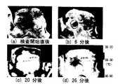
図2に検査過程における温度分布画像の一例を示す。
図2(a)は脱衣直後(測定を始めて0分後)、同図(b)は送風による冷却時(6分後)、同図(c)はFIRヒータによる加熱時(20分後)、同図(d)は加熱停止後(26分後)の温度分布画像である。
この一例では、円形リングで囲まれている左胸部上方に悪性腫瘍がある。FIG. 2 shows an example of a temperature distribution image in the inspection process.
FIG. 2 (a) is immediately after undressing (after 0 minutes from the start of measurement), FIG. 2 (b) is during cooling by air blowing (after 6 minutes), FIG. 2 (c) is during heating by an FIR heater (after 20 minutes), FIG. 4D is a temperature distribution image after heating is stopped (after 26 minutes).
In this example, there is a malignant tumor above the left chest surrounded by a circular ring.
図3に解析対象とした悪性腫瘍部(malignancy)、正常組織である体幹中央部(center region)、比較対象として腫瘍部と左右対称に位置する正常組織(opposite region)をそれぞれ示す。
図4に上記各部位における温度の経時変化を表し、横軸が経時時間、縦軸が表面温度を示す。
図4に示すように測定を始めてから5分から10分まで強制的に体表面を冷却(Cooling)しているが、悪性腫瘍部(malignancy)では温度低下が少ないことがわかる。
これは悪性腫瘍の内部及び周辺には栄養血管が増殖するため、正常組織に比べ血流が多いためと考えられる。
また、15分から25分までFIRヒータにより加熱(Heating)しているが、いずれの測定点においても平熱を上回る38℃以上に加熱できたことが確認できる。
なお、加熱を開始してからの1分後および3分後にFIRヒータを1分間外し、温度分布を測定した。FIG. 3 shows a malignant tumor part (malignancy) as an analysis target, a trunk central part (center region) as a normal tissue, and a normal tissue (opposite region) positioned symmetrically with the tumor part as a comparison target.
FIG. 4 shows changes with time in the temperatures at the respective sites, with the horizontal axis representing the time elapsed and the vertical axis representing the surface temperature.
As shown in FIG. 4, the body surface is forcibly cooled from 5 minutes to 10 minutes after the start of the measurement, but it can be seen that there is little temperature drop in the malignancy.
This is probably because nutrient blood vessels grow in and around the malignant tumor, resulting in more blood flow than normal tissues.
Moreover, although it heated with the FIR heater from 15 minutes to 25 minutes, it can confirm that it was able to heat to 38 degreeC or more which exceeds a normal temperature in any measurement point.
The FIR heater was removed for 1
次に、正常組織(opposite region)に対する温度差をプロットした経時変化のグラフを図5に示す。
太い実線は悪性腫瘍部(malignancy)の温度変化パターン、破線部は体幹中央部(center region)の温度変化パターンを示す。
正常組織(opposite region)との温度差は、体表面冷却(Cooling)時に広がり、加熱(Heating)時に温度差が接近もしくは逆転することがわかる。
このプロファイルは悪性腫瘍部位に多く見られる栄養血管によるものであり、悪性腫瘍を自動的に抽出する画像処理プログラムを作成する際のマーカーとして利用できることが確認できる。Next, FIG. 5 shows a graph of change over time in which a temperature difference with respect to a normal region (opposite region) is plotted.
The thick solid line shows the temperature change pattern of the malignancy, and the broken line shows the temperature change pattern of the center region.
It can be seen that the temperature difference from the normal region spreads when the body surface is cooled (cooling), and the temperature difference approaches or reverses when heated (heating).
This profile is due to the nutritional blood vessels often found in the malignant tumor site, and it can be confirmed that it can be used as a marker when creating an image processing program for automatically extracting a malignant tumor.
さらに、各測定部位におけるFIRヒータのよる加熱1分後、2分後、8分後のdTs/dTrを図6に示す。
加熱初期の加熱1分の時点では悪性腫瘍部(malignancy)の温度変化が小さく、血管(blood vessel)の温度が高くなっている。
生体組織の熱伝導率は脂肪で0.0005cal/(s・cm2・℃)、筋肉で0.001cal/(s・cm2・℃)、直径0.1mm程度の血管を流れる血流で0.24cal/(s・cm2・℃)であり、血管は他の組織に比べ数百倍の熱量の輸送能力がある。
周辺組織で温められた血液が血管(blood vessel)に流入したために、短時間に血管(blood vessel)の温度が急上昇したものと考えられる。
一方、2分を過ぎると血管(blood vessel)と悪性腫瘍部(malignancy)との差は少なくなるが、血管が少なく脂肪の多い組織は蓄熱されやすいため、温度が上昇している。
血管が豊富な組織は血流により冷却されるため、一定温度に収束していく。
加熱の初期段階において血管(blood vessel)と悪性腫瘍部(malignancy)の昇温特性が異なるとの知見は本発明の根幹となる考えであり、赤外線画像から悪性腫瘍部(malignancy)を自動抽出するプログラムを作成する上で必要不可欠な知見になっている。Furthermore, FIG. 6 shows dTs / dTr after 1 minute, 2 minutes, and 8 minutes after heating by the FIR heater at each measurement site.
At the time of heating for 1 minute in the initial stage of heating, the temperature change of the malignant tumor (malignancy) is small, and the temperature of the blood vessel is high.
The thermal conductivity of the living tissue0.0005cal / (s · cm 2 · ℃)fat, 0.001cal / (s · cm 2 · ℃) in muscle, 0 with blood flow through the blood vessel having a diameter of about 0.1mm .24 cal / (s · cm2 · ° C.), and blood vessels have a heat capacity of several hundred times that of other tissues.
It is considered that the temperature of the blood vessel rapidly increased in a short time because the blood warmed in the surrounding tissue flowed into the blood vessel.
On the other hand, after 2 minutes, the difference between the blood vessel and the malignancy is reduced, but the tissue with fewer blood vessels and more fatty tissue tends to store heat, so the temperature rises.
Since the tissue rich in blood vessels is cooled by the blood flow, it converges to a certain temperature.
The knowledge that the temperature rise characteristics of blood vessels and malignant tumors (malignancy) are different at the initial stage of heating is a fundamental idea of the present invention, and malignant tumors (malignancy) are automatically extracted from infrared images. This knowledge is indispensable for creating a program.
1 発信器
2 サーマルカメラ
3 熱画像解析用コンピュータ(画像処理装置)
4 シャッター
5 シャッター開閉制御ユニット
6 ハーフミラー
1
4 Shutter 5 Shutter open /
Claims (3)
Translated fromJapaneseThe FIR active thermography inspection apparatus according to claim 1, wherein a half mirror for photographing a temperature distribution by the thermal camera is provided between the shutter mechanism and a measurement object.
Priority Applications (1)
| Application Number | Priority Date | Filing Date | Title |
|---|---|---|---|
| JP2006040540AJP4324651B2 (en) | 2006-02-17 | 2006-02-17 | FIR active thermography inspection system |
Applications Claiming Priority (1)
| Application Number | Priority Date | Filing Date | Title |
|---|---|---|---|
| JP2006040540AJP4324651B2 (en) | 2006-02-17 | 2006-02-17 | FIR active thermography inspection system |
Publications (2)
| Publication Number | Publication Date |
|---|---|
| JP2007215809Atrue JP2007215809A (en) | 2007-08-30 |
| JP4324651B2 JP4324651B2 (en) | 2009-09-02 |
Family
ID=38493679
Family Applications (1)
| Application Number | Title | Priority Date | Filing Date |
|---|---|---|---|
| JP2006040540AActiveJP4324651B2 (en) | 2006-02-17 | 2006-02-17 | FIR active thermography inspection system |
Country Status (1)
| Country | Link |
|---|---|
| JP (1) | JP4324651B2 (en) |
Cited By (11)
| Publication number | Priority date | Publication date | Assignee | Title |
|---|---|---|---|---|
| JP2009279355A (en)* | 2008-05-26 | 2009-12-03 | Konica Minolta Medical & Graphic Inc | Ultrasonic diagnostic method and apparatus |
| JP2010504763A (en)* | 2006-01-09 | 2010-02-18 | メディカル オプティカル イメージング システムズ エルティーディ. | Infrared passive and active tomographic imaging methods suitable for early diagnosis of breast cancer |
| KR100943709B1 (en) | 2007-11-13 | 2010-02-23 | 한국표준과학연구원 | Infrared thermography system and control method |
| JP2010194005A (en)* | 2009-02-24 | 2010-09-09 | Seikei Gakuen | Respiration measuring method and respiration measuring device |
| RU2435522C2 (en)* | 2009-05-22 | 2011-12-10 | Александр Иванович Беленко | Method of deciphering infrared irradiation from human body surface by method of computer thermography |
| JP2013515586A (en)* | 2009-12-29 | 2013-05-09 | ペルセウス−バイオメッド インコーポレイテッド | Method and system for tissue recognition |
| RU2566214C1 (en)* | 2014-07-07 | 2015-10-20 | Федеральное государственное бюджетное учреждение науки Институт механики сплошных сред Уральского отделения Российской академии наук | Diagnostic technique for breast cancer |
| CN106108854A (en)* | 2016-07-18 | 2016-11-16 | 深圳市衣信互联网科技有限公司 | Underwear infrared light heat radiation detection system and the method for detection radiation field status information |
| JP2019198531A (en)* | 2018-05-17 | 2019-11-21 | Cyberdyne株式会社 | Biological information measurement device and biological information measurement method |
| CN112512407A (en)* | 2018-06-12 | 2021-03-16 | H.T生物成像公司 | System, method and computer product for differentiating between tissue states and types |
| CN114027803A (en)* | 2021-12-01 | 2022-02-11 | 中国人民解放军空军特色医学中心 | Internal balance detection device based on temperature field distribution |
- 2006
- 2006-02-17JPJP2006040540Apatent/JP4324651B2/enactiveActive
Cited By (18)
| Publication number | Priority date | Publication date | Assignee | Title |
|---|---|---|---|---|
| JP2010504763A (en)* | 2006-01-09 | 2010-02-18 | メディカル オプティカル イメージング システムズ エルティーディ. | Infrared passive and active tomographic imaging methods suitable for early diagnosis of breast cancer |
| KR100943709B1 (en) | 2007-11-13 | 2010-02-23 | 한국표준과학연구원 | Infrared thermography system and control method |
| JP2009279355A (en)* | 2008-05-26 | 2009-12-03 | Konica Minolta Medical & Graphic Inc | Ultrasonic diagnostic method and apparatus |
| JP2010194005A (en)* | 2009-02-24 | 2010-09-09 | Seikei Gakuen | Respiration measuring method and respiration measuring device |
| RU2435522C2 (en)* | 2009-05-22 | 2011-12-10 | Александр Иванович Беленко | Method of deciphering infrared irradiation from human body surface by method of computer thermography |
| JP2013515586A (en)* | 2009-12-29 | 2013-05-09 | ペルセウス−バイオメッド インコーポレイテッド | Method and system for tissue recognition |
| RU2566214C1 (en)* | 2014-07-07 | 2015-10-20 | Федеральное государственное бюджетное учреждение науки Институт механики сплошных сред Уральского отделения Российской академии наук | Diagnostic technique for breast cancer |
| CN106108854B (en)* | 2016-07-18 | 2019-09-17 | 深圳市衣信互联网科技有限公司 | The infrared optical heat radiation detection system of underwear and the method for detecting radiation field status information |
| CN106108854A (en)* | 2016-07-18 | 2016-11-16 | 深圳市衣信互联网科技有限公司 | Underwear infrared light heat radiation detection system and the method for detection radiation field status information |
| JP2019198531A (en)* | 2018-05-17 | 2019-11-21 | Cyberdyne株式会社 | Biological information measurement device and biological information measurement method |
| JP7132568B2 (en) | 2018-05-17 | 2022-09-07 | Cyberdyne株式会社 | Biological information measuring device and biological information measuring method |
| CN112512407A (en)* | 2018-06-12 | 2021-03-16 | H.T生物成像公司 | System, method and computer product for differentiating between tissue states and types |
| JP2021527474A (en)* | 2018-06-12 | 2021-10-14 | エイチ.ティー バイオイメージング リミテッド | Systems, methods and computer products to distinguish the state and type of organization |
| JP7459000B2 (en) | 2018-06-12 | 2024-04-01 | エイチ.ティー バイオイメージング リミテッド | System for distinguishing tissue states and how to control this |
| US12029529B2 (en) | 2018-06-12 | 2024-07-09 | H.T Bioimaging Ltd. | System, method and computer product for differentiating between tissue states and types |
| CN112512407B (en)* | 2018-06-12 | 2025-01-10 | H.T生物成像公司 | Systems, methods, and computer products for distinguishing between organizational states and types |
| US12318169B2 (en) | 2018-06-12 | 2025-06-03 | H.T Bioimaging Ltd. | System, method and computer product for differentiating between tissue states and types |
| CN114027803A (en)* | 2021-12-01 | 2022-02-11 | 中国人民解放军空军特色医学中心 | Internal balance detection device based on temperature field distribution |
Also Published As
| Publication number | Publication date |
|---|---|
| JP4324651B2 (en) | 2009-09-02 |
Similar Documents
| Publication | Publication Date | Title |
|---|---|---|
| JP4324651B2 (en) | FIR active thermography inspection system | |
| Jones | A reappraisal of the use of infrared thermal image analysis in medicine | |
| Knobel et al. | Thermoregulation and thermography in neonatal physiology and disease | |
| Buzug et al. | Functional infrared imaging for skin-cancer screening | |
| Gonzalez-Hernandez et al. | Technology, application and potential of dynamic breast thermography for the detection of breast cancer | |
| Barnes | Thermography of the Human Body: Infrared-radiant energy provides new concepts and instrumentation for medical diagnosis. | |
| Amri et al. | Potentialities of steady-state and transient thermography in breast tumour depth detection: A numerical study | |
| González | Thermal simulation of breast tumors | |
| CN103338694B (en) | For the method and apparatus of the surface temperature of part of having a physical examination | |
| Just et al. | Monitoring of microvascular free flaps following oropharyngeal reconstruction using infrared thermography: first clinical experiences | |
| Cheng et al. | Analysis of skin cooling for quantitative dynamic infrared imaging of near-surface lesions | |
| US20200329975A1 (en) | Device and method for cancer detection, diagnosis and treatment guidance using active thermal imaging | |
| TWI286927B (en) | Method and apparatus for producing images of infrared radiation of a patient | |
| Barnes | Diagnostic thermography | |
| US20190167117A1 (en) | Method of Monitoring the Status of a Wound | |
| JP3939487B2 (en) | Thermophysical property measurement system | |
| Bonmarin et al. | Thermal imaging in dermatology | |
| Živčák et al. | Methodology, Models and Algorithms in Thermographic Diagnostics | |
| JPH11347015A (en) | Personal feature pattern detection device | |
| CN101310672A (en) | Method and system for imaging a target surface with an infrared thermal map | |
| Kirimtat et al. | Flir vs seek in biomedical applications of infrared thermography | |
| Amri et al. | Potentialities of dynamic breast thermography | |
| RU2276965C2 (en) | Method for setting early stage mammary gland tumor disease diagnosis | |
| Kaczmarek | A new diagnostic IR-thermal imaging method for evaluation of cardiosurgery procedures | |
| US20170296064A9 (en) | Method of Monitoring The Status of A Wound |
Legal Events
| Date | Code | Title | Description |
|---|---|---|---|
| A621 | Written request for application examination | Free format text:JAPANESE INTERMEDIATE CODE: A621 Effective date:20090127 | |
| A871 | Explanation of circumstances concerning accelerated examination | Free format text:JAPANESE INTERMEDIATE CODE: A871 Effective date:20090127 | |
| A975 | Report on accelerated examination | Free format text:JAPANESE INTERMEDIATE CODE: A971005 Effective date:20090216 | |
| A131 | Notification of reasons for refusal | Free format text:JAPANESE INTERMEDIATE CODE: A131 Effective date:20090220 | |
| A521 | Request for written amendment filed | Free format text:JAPANESE INTERMEDIATE CODE: A523 Effective date:20090323 | |
| TRDD | Decision of grant or rejection written | ||
| A01 | Written decision to grant a patent or to grant a registration (utility model) | Free format text:JAPANESE INTERMEDIATE CODE: A01 Effective date:20090413 | |
| A01 | Written decision to grant a patent or to grant a registration (utility model) | Free format text:JAPANESE INTERMEDIATE CODE: A01 | |
| A61 | First payment of annual fees (during grant procedure) | Free format text:JAPANESE INTERMEDIATE CODE: A61 Effective date:20090515 | |
| R150 | Certificate of patent or registration of utility model | Free format text:JAPANESE INTERMEDIATE CODE: R150 |