JP2007209966A - Gas separation device - Google Patents
Gas separation deviceDownload PDFInfo
- Publication number
- JP2007209966A JP2007209966AJP2006063337AJP2006063337AJP2007209966AJP 2007209966 AJP2007209966 AJP 2007209966AJP 2006063337 AJP2006063337 AJP 2006063337AJP 2006063337 AJP2006063337 AJP 2006063337AJP 2007209966 AJP2007209966 AJP 2007209966A
- Authority
- JP
- Japan
- Prior art keywords
- hollow fiber
- fiber bundle
- outer tube
- separation device
- gas
- Prior art date
- Legal status (The legal status is an assumption and is not a legal conclusion. Google has not performed a legal analysis and makes no representation as to the accuracy of the status listed.)
- Pending
Links
Images


Classifications
- B—PERFORMING OPERATIONS; TRANSPORTING
- B01—PHYSICAL OR CHEMICAL PROCESSES OR APPARATUS IN GENERAL
- B01D—SEPARATION
- B01D65/00—Accessories or auxiliary operations, in general, for separation processes or apparatus using semi-permeable membranes
- B01D65/02—Membrane cleaning or sterilisation ; Membrane regeneration
- B—PERFORMING OPERATIONS; TRANSPORTING
- B01—PHYSICAL OR CHEMICAL PROCESSES OR APPARATUS IN GENERAL
- B01D—SEPARATION
- B01D53/00—Separation of gases or vapours; Recovering vapours of volatile solvents from gases; Chemical or biological purification of waste gases, e.g. engine exhaust gases, smoke, fumes, flue gases, aerosols
- B01D53/22—Separation of gases or vapours; Recovering vapours of volatile solvents from gases; Chemical or biological purification of waste gases, e.g. engine exhaust gases, smoke, fumes, flue gases, aerosols by diffusion
- B—PERFORMING OPERATIONS; TRANSPORTING
- B01—PHYSICAL OR CHEMICAL PROCESSES OR APPARATUS IN GENERAL
- B01D—SEPARATION
- B01D61/00—Processes of separation using semi-permeable membranes, e.g. dialysis, osmosis or ultrafiltration; Apparatus, accessories or auxiliary operations specially adapted therefor
- B—PERFORMING OPERATIONS; TRANSPORTING
- B01—PHYSICAL OR CHEMICAL PROCESSES OR APPARATUS IN GENERAL
- B01D—SEPARATION
- B01D63/00—Apparatus in general for separation processes using semi-permeable membranes
- B01D63/02—Hollow fibre modules
- C—CHEMISTRY; METALLURGY
- C01—INORGANIC CHEMISTRY
- C01B—NON-METALLIC ELEMENTS; COMPOUNDS THEREOF; METALLOIDS OR COMPOUNDS THEREOF NOT COVERED BY SUBCLASS C01C
- C01B13/00—Oxygen; Ozone; Oxides or hydroxides in general
- C01B13/02—Preparation of oxygen
- C01B13/0229—Purification or separation processes
- C01B13/0248—Physical processing only
- C01B13/0251—Physical processing only by making use of membranes
- B—PERFORMING OPERATIONS; TRANSPORTING
- B01—PHYSICAL OR CHEMICAL PROCESSES OR APPARATUS IN GENERAL
- B01D—SEPARATION
- B01D2313/00—Details relating to membrane modules or apparatus
- B01D2313/23—Specific membrane protectors, e.g. sleeves or screens
- C—CHEMISTRY; METALLURGY
- C01—INORGANIC CHEMISTRY
- C01B—NON-METALLIC ELEMENTS; COMPOUNDS THEREOF; METALLOIDS OR COMPOUNDS THEREOF NOT COVERED BY SUBCLASS C01C
- C01B2210/00—Purification or separation of specific gases
- C01B2210/0043—Impurity removed
- C01B2210/0046—Nitrogen
Landscapes
- Chemical & Material Sciences (AREA)
- Chemical Kinetics & Catalysis (AREA)
- Analytical Chemistry (AREA)
- Organic Chemistry (AREA)
- Engineering & Computer Science (AREA)
- General Chemical & Material Sciences (AREA)
- Oil, Petroleum & Natural Gas (AREA)
- Inorganic Chemistry (AREA)
- Water Supply & Treatment (AREA)
- Separation Using Semi-Permeable Membranes (AREA)
- Oxygen, Ozone, And Oxides In General (AREA)
Abstract
Translated fromJapaneseDescription
Translated fromJapanese本発明は可撓型気体分離装置に関する。 The present invention relates to a flexible gas separation device.
窒素分離装置は、樹脂製の中空糸を使用して空気中の酸素と窒素を分離させるものである。
樹脂素材による気体分離装置は広く普及しており、特に大気中の空気から窒素を分離して窒素ボンベの代わりに溶接作業等に使用することが既に行われている。その他、窒素の利用法としては、酸化防止用、爆発防止、青果物の貯蔵等がある。The nitrogen separator uses a resin hollow fiber to separate oxygen and nitrogen in the air.
Gas separation devices made of resin materials are widely used, and in particular, nitrogen has already been separated from air in the atmosphere and used for welding work or the like instead of a nitrogen cylinder. Other uses of nitrogen include oxidation prevention, explosion prevention, and storage of fruits and vegetables.
従来の気体分離装置は、第5図に示す通り、端部がキャップ状の気密構造になっている樹脂製または金属製のケース101からなっている。 ケースの中には中空糸膜102が収納され、図5においてケースの上部から圧縮空気を注入し、ケースの下部から窒素ガスを取り出すようになっている。
酸素ガスは中空糸膜の途中から分離されるので、ケース101には酸素ガス排気用の孔103があけてある。
Since oxygen gas is separated from the middle of the hollow fiber membrane, the
従来の気体分離装置は、樹脂製中空糸としてポリイミドを使用しているため、装置そのものが剛構造でありあるため一定の大きさの形状となり、設置時や運搬時に柔軟性を欠くという欠点があった。
本発明は、可撓性を有し、装置を小型化でき、設置時や輸送時に柔軟に対応で出来る気体分離装置の提供を目的とする。Since conventional gas separation devices use polyimide as a resin hollow fiber, the device itself has a rigid structure and has a certain size and lacks flexibility during installation and transportation. It was.
An object of the present invention is to provide a gas separation device that is flexible, can be downsized, and can be flexibly adapted during installation and transportation.
本発明は、圧縮空気を窒素含有ガス及び酸素含有ガスに分離する可撓性の中空糸束と、前記中空糸束を被覆し、前記中空糸束で分離された酸素含有ガスを排出する排気口を有する可撓性の外筒チューブと、を有することを特徴とする。これにより、単純で変形自在な構造で装置を小型化でき、かつ高純度の窒素を分離することが出来る。 The present invention relates to a flexible hollow fiber bundle that separates compressed air into a nitrogen-containing gas and an oxygen-containing gas, and an exhaust port that covers the hollow fiber bundle and discharges the oxygen-containing gas separated by the hollow fiber bundle. And a flexible outer tube. Thereby, the apparatus can be miniaturized with a simple and deformable structure, and high-purity nitrogen can be separated.
前記中空糸束と前記外筒チューブとを気密に保ち、前記開口部は、前記圧縮空気入口端側に設けられたことを特徴とする。 The hollow fiber bundle and the outer tube are kept airtight, and the opening is provided on the compressed air inlet end side.
前記中空糸束及び前記外筒チューブの少なくとも前記窒素ガス出口端側を密着することで前記中空糸束と外筒チューブとの空間に、前記窒素ガス出口端側から前記圧縮空気入口端側へ流れる酸素含有ガスの気流が形成されてることで、前記中空糸の外側が気密が保たれていることを特徴とする。 By adhering at least the nitrogen gas outlet end side of the hollow fiber bundle and the outer cylinder tube, it flows into the space between the hollow fiber bundle and the outer cylinder tube from the nitrogen gas outlet end side to the compressed air inlet end side. By forming an air flow of the oxygen-containing gas, the outside of the hollow fiber is kept airtight.
前記中空糸束は、ポリスルフォンやポリイミド等の可撓性樹脂であることを特徴とする。 The hollow fiber bundle is a flexible resin such as polysulfone or polyimide.
前記外筒チューブは、金属製の蛇腹、樹脂、ゴム、または布製のいずれかであることを特徴とする。 The outer tube is made of metal bellows, resin, rubber, or cloth.
前記外筒チューブは、ポリプロピレン(PP)またはポリエチレン(PE)等の樹脂製フィルムであることを特徴とする。 The outer tube is a resin film such as polypropylene (PP) or polyethylene (PE).
前記中空糸束及び前記外筒チューブが収納される収納部を有する匡体を備え、
前記匡体には、前記中空糸束及び前記外筒チューブの一端が接続又は開放される前記圧縮空気の流入部と、他端が接続される前記窒素含有ガスの排出部が設けられ、
前記収納部には、前記排気口から排出される酸素含有ガスを収納部外に排出する換気口が設けられていることを特徴とする。Comprising a housing having a storage portion for storing the hollow fiber bundle and the outer tube;
The casing is provided with an inflow portion of the compressed air to which one end of the hollow fiber bundle and the outer tube is connected or opened, and a discharge portion for the nitrogen-containing gas to which the other end is connected,
The storage unit is provided with a ventilation port for discharging the oxygen-containing gas discharged from the exhaust port to the outside of the storage unit.
本発明は、気体分離装置の中空糸束と外筒チューブが可撓性を有するために自由に変形させることができ、長さも調節可能であるため、装置を小型化できて、設置場所や輸送手段に柔軟に対応できる利点がある。 Since the hollow fiber bundle and the outer tube of the gas separation device have flexibility, the present invention can be freely deformed and the length can be adjusted, so that the device can be miniaturized, and can be installed and transported. There is an advantage that the means can be flexibly handled.
以下、本発明の実施例を図面を参照して詳細に説明する。
本発明は、樹脂製中空糸により空気から窒素を分離する気体分離装置に関するものである。
樹脂製中空糸による膜分離法は、膜に対する透過速度の差により分離する方法で、構造が簡単で立ち上がりも早いため小規模生産に向いている。Hereinafter, embodiments of the present invention will be described in detail with reference to the drawings.
The present invention relates to a gas separation device that separates nitrogen from air with a resin hollow fiber.
The membrane separation method using a resin hollow fiber is a method of separation based on the difference in permeation rate with respect to the membrane, and is suitable for small-scale production because of its simple structure and quick start-up.
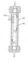
膜分離法は高分子中空糸膜が、空気中の窒素より酸素、水素、水分を透過しやすい性質を利用するもので、図1に示す通り、中空糸膜1の中に圧縮空気を通し、空気中の各成分の透過速度の差を利用して、酸素を分離し、分離速度の遅い窒素ガスを空気中から抽出する方法である。
中空糸膜1の径は0.2mm程度以下であり、これを何万本も束ねて膜モジュールとする。The membrane separation method utilizes the property that the polymer hollow fiber membrane is more permeable to oxygen, hydrogen, and moisture than nitrogen in the air. As shown in FIG. 1, compressed air is passed through the hollow fiber membrane 1, This is a method in which oxygen is separated by utilizing a difference in permeation speed of each component in the air, and nitrogen gas having a slow separation speed is extracted from the air.
The hollow fiber membrane 1 has a diameter of about 0.2 mm or less, and tens of thousands of them are bundled to form a membrane module.
中空糸膜1の材料として、ポリスルホンは安価で軟らかいため加工性にも優れ、経年変化も少ない特長がある。気体分離能力も99.90%と良好である。なお、可撓性を有すればポリイミド製であってもよい。 As a material for the hollow fiber membrane 1, polysulfone is inexpensive and soft, so that it has excellent processability and little secular change. The gas separation capacity is also good at 99.90%. Note that it may be made of polyimide as long as it has flexibility.
図1、図2に示す通り、本発明による空気分離装置は、可撓性を有する中空糸束1と、中空糸束1を収納し、圧縮空気入り口側に分離された酸素を排出する酸素排出口8を有する可撓性の外筒チューブ3と、外筒チューブ3の両端に装着し、外筒チューブ3を保持するホルダー5と、ホルダー5に外装してホルダー5を保護するエンドキャップ2と、外筒チューブ3の窒素出口側のホルダー5を固定して外筒チューブ3の窒素出口側を気密に保つシール4とからなってなっている。 As shown in FIGS. 1 and 2, an air separation device according to the present invention includes a hollow fiber bundle 1 having flexibility, and an oxygen exhaust that houses the hollow fiber bundle 1 and discharges the separated oxygen to the compressed air inlet side. A flexible outer tube 3 having an
中空糸膜1としては、可撓性を持たせるためにポリスルフォン製を使用する。外筒チューブ3は、金属製の蛇腹、PP,PE等の樹脂、ゴム、または布製で何れも気体を通さないものを使用する。外筒チューブ3を金属製にする場合は、可撓性を持たせるために蛇腹方式にする必要がある。外筒チューブ3を布製にする場合は、通気性をもたせないようにするために表面に通気を防ぐ樹脂またはゴムの層をコーティングして使用する。 The hollow fiber membrane 1 is made of polysulfone so as to have flexibility. The outer tube 3 is made of a metal bellows, resin such as PP or PE, rubber, or cloth that does not allow gas to pass through. When the outer tube 3 is made of metal, it is necessary to adopt a bellows type in order to provide flexibility. When the outer tube 3 is made of cloth, a resin or rubber layer that prevents ventilation is coated on the surface in order to prevent breathability.
本実施例では、中空糸束1000本以上で長さ1800mmのポリスルフォン樹脂製中空糸膜1を使用した。(なお、1000本以下の場合でもよい。)中空糸膜1の膜厚は200μm、外径は500μmである。なお、可撓性があればポリイミド樹脂製であってもよい。
まず、中空糸束1を外形22mmのポリプロピレン(PP)製外筒チューブ3に挿入するが、その際、圧縮空気入り口側に、開口部として酸素ガス排気口8がくるようにする。
外筒チューブ3の両端からはみ出した中空糸束1の両端には長さ25mm、外径22mmのPP製ホルダー5を取り付けるとともに、外筒チューブ3の両端をホルダー5の外周に嵌め込んで結合する。
その後、ホルダー5にPP製エンドキャップ2を外装し、窒素出口側の外筒チューブ3とホルダー5の結合部にはウレタンゴム製のシール4を巻き付けて固定する。
本実施例の気体分離装置7は、図4に示すように、直径320mmの円になるように丸めて段ボール箱に入れ、出荷する。
本実施例の気体分離装置7は、可撓式であるため、外筒チューブ3の窒素出口を窒素の使用環境に応じて作業に最適な位置に置くことが出来る。In this example, a hollow fiber membrane 1 made of polysulfone resin having 1000 or more hollow fiber bundles and a length of 1800 mm was used. (It may be 1000 or less.) The hollow fiber membrane 1 has a thickness of 200 μm and an outer diameter of 500 μm. Note that it may be made of polyimide resin as long as it is flexible.
First, the hollow fiber bundle 1 is inserted into a polypropylene (PP) outer tube 3 having an outer diameter of 22 mm. At this time, an oxygen
A PP holder 5 having a length of 25 mm and an outer diameter of 22 mm is attached to both ends of the hollow fiber bundle 1 protruding from both ends of the outer tube 3, and both ends of the outer tube 3 are fitted to the outer periphery of the holder 5 to be coupled. .
After that, the
As shown in FIG. 4, the gas separation device 7 of the present embodiment is rolled into a circle with a diameter of 320 mm, placed in a cardboard box, and shipped.
Since the gas separation device 7 of the present embodiment is flexible, the nitrogen outlet of the outer tube 3 can be placed at an optimum position for work according to the use environment of nitrogen.
本実施例の気体分離装置7に、圧力0.5MPa、20℃のドレン、ミストを除去した圧縮空気を流量0.5Nm3/hr供給した結果、得られた窒素濃度は95.00%〜99.90%の範囲であり、ガスの大気圧露点は−11℃と低露点であった。
窒素ガスの発生量と濃度は圧縮空気の供給圧と温度に依存し、濃度が一定のとき、圧縮空気の供給が高圧、また周辺温度が高温になるに従いそれぞれ発生量は増大する。
コメントAs a result of supplying compressed air from which drain and mist were removed at a pressure of 0.5 MPa and 20 ° C. to the gas separator 7 of this example at a flow rate of 0.5 Nm 3 / hr, the resulting nitrogen concentration was 95.00% to 99.99. The range was 90%, and the atmospheric dew point of the gas was -11 ° C. and a low dew point.
The generation amount and concentration of nitrogen gas depend on the supply pressure and temperature of the compressed air. When the concentration is constant, the generation amount increases as the supply of compressed air increases and the ambient temperature increases.
comment
図3に示す通り、本実施例は、ホルダー5に保持され外筒チューブ3に覆われた中空糸束1を匡体6に収納し、匡体6に圧縮空気入り口金具9と窒素出口金具10を装備したものである。
匡体6は、ホルダー5に保持され外筒チューブ3に覆われた中空糸束1が収納され、圧縮空気入り口側ホルダー5が嵌合する孔11と、圧縮空気入り口金具9と、圧縮空気入り口側ホルダー5と圧縮空気入り口金具とをつなぐ通路12と、窒素出口側ホルダー5が嵌合する孔11と、窒素出口金具10と、窒素出口側ホルダー5と窒素出口金具10とをつなぐ通路12と、分離された酸素等を排出する酸素排出口13と、から構成されているが、この匡体6に収納されていること以外は実施例1と同じ構成であるため、実施例1とダブル部分は説明を省略する。
本実施例は、窒素の使用位置が固定されている場合などに適用すると便利である。As shown in FIG. 3, in this embodiment, the hollow fiber bundle 1 held by the holder 5 and covered with the outer tube 3 is accommodated in the
The
This embodiment is convenient when applied when the use position of nitrogen is fixed.
なお、上記実施例では空気分離装置は、可撓性を有する中空糸束1を覆う外筒チューブ3の端部を圧縮空気入り口側でエンドキャップ2に固定し、外筒チューブ3の圧縮空気入り口側付近に酸素ガス排気口8を設けたが、この構造に限られることなく、圧縮空気入り口側の外筒チューブ3をエンドキャップ2に固定しないで中空糸束1に被服した構造とし、これら中空糸束1と外筒チューブ3を変形させた際に、外筒チューブ3がエンドキャップ2から離れて自由にスライドして、圧縮空気入り口側でエンドキャップ2との間に開口部を形成するようにしてもよい、これによって中空糸束1と外筒チューブ3を任意の形に変形させた場合に、長手方向の寸法調整を容易に行うことができると共に、空気含有ガスは外筒チューブ3とエンドキャップ2と固定された窒素ガス出口端側から開口部が形成された圧縮空気入り口側へ、中空糸束1と外筒チューブ3の間を流れて開口部から流出するようになる。これによって気密も保持され中空糸束1の外周が乾燥することもなくなる。 In the above embodiment, the air separation device fixes the end of the outer tube 3 covering the flexible hollow fiber bundle 1 to the
本実施例の気体分離装置7で得られる窒素ガスの濃度は約99.90%であるが、中空糸束1、エンドキャップ2、外筒チューブ3、シール4、ホルダー5からなる単純な構造であるため装置を小型にすることができ、故障しやすい箇所や消耗品が少ないため故障個所が殆どなく、メンテナンスが不要である。また、中空糸束で分離される方式であるため所定の濃度までの立ち上げ時間が短く、高圧空気ラインに接続するだけで高純度窒素ガスが得られる特長がある。 The concentration of nitrogen gas obtained by the gas separation device 7 of this embodiment is about 99.90%, but it has a simple structure comprising the hollow fiber bundle 1, the
なお、上記実施例では気体分離装置7を空気中の各成分の透過速度の差を利用して、酸素を分離し、分離速度の遅い窒素ガスを空気中から抽出し、窒素ガスの利用をする方法に用いた例を説明したが、この気体分離装置7の外筒チューブ側の開口部から抽出される酸素を有効活用することもできる。 In the above embodiment, the gas separation device 7 uses the difference in permeation speed of each component in the air to separate oxygen, extract nitrogen gas having a slow separation speed from the air, and use nitrogen gas. Although the example used in the method has been described, oxygen extracted from the opening on the outer tube side of the gas separation device 7 can be effectively utilized.
1 中空糸膜、中空糸束
2 エンドキャップ
3 外筒チューブ
4 シール
5 ホルダー
6 筐体
7 気体分離装置
8 酸素排出口
9 圧縮空気入り口金具
10 窒素出口金具
11 孔
12 通路
13 酸素排出口
101 ケース
102 中空糸膜
103 孔DESCRIPTION OF SYMBOLS 1 Hollow fiber membrane,
Claims (7)
Translated fromJapanese前記中空糸束を被覆し、前記中空糸束で分離された酸素含有ガスを排出する開口部を有する可撓性の外筒チューブと、
を有することを特徴とする気体分離装置。A flexible hollow fiber bundle that separates compressed air into nitrogen-containing gas and oxygen-containing gas;
A flexible outer tube that covers the hollow fiber bundle and has an opening for discharging the oxygen-containing gas separated by the hollow fiber bundle;
A gas separation device comprising:
前記匡体には、前記中空糸束及び前記外筒チューブの一端が接続又は開放される前記圧縮空気の流入部と、他端が接続される前記窒素含有ガスの排出部が設けられ、
前記収納部には、前記排気口から排出される酸素含有ガスを収納部外に排出する換気口が設けられていることを特徴とする請求項1〜6のいずれかに記載の気体分離装置。Comprising a housing having a storage portion for storing the hollow fiber bundle and the outer tube;
The casing is provided with an inflow portion of the compressed air to which one end of the hollow fiber bundle and the outer tube is connected or opened, and a discharge portion for the nitrogen-containing gas to which the other end is connected,
The gas separation device according to any one of claims 1 to 6, wherein the storage portion is provided with a ventilation port for discharging the oxygen-containing gas discharged from the exhaust port to the outside of the storage portion.
Priority Applications (6)
| Application Number | Priority Date | Filing Date | Title |
|---|---|---|---|
| JP2006063337AJP2007209966A (en) | 2006-02-09 | 2006-02-09 | Gas separation device |
| TW095138747ATW200732029A (en) | 2006-02-09 | 2006-10-20 | An apparatus for separating elements in the air |
| CNA2006101724114ACN101015764A (en) | 2006-02-09 | 2006-12-26 | An apparatus for separating elements in the air |
| KR1020070009837AKR20070081088A (en) | 2006-02-09 | 2007-01-31 | Gas Separator |
| EP07002852AEP1820559A1 (en) | 2006-02-09 | 2007-02-09 | An apparatus for separating elements in the air |
| US11/673,370US20070186773A1 (en) | 2006-02-09 | 2007-02-09 | Apparatus for separating elements in the air |
Applications Claiming Priority (1)
| Application Number | Priority Date | Filing Date | Title |
|---|---|---|---|
| JP2006063337AJP2007209966A (en) | 2006-02-09 | 2006-02-09 | Gas separation device |
Publications (1)
| Publication Number | Publication Date |
|---|---|
| JP2007209966Atrue JP2007209966A (en) | 2007-08-23 |
Family
ID=38007039
Family Applications (1)
| Application Number | Title | Priority Date | Filing Date |
|---|---|---|---|
| JP2006063337APendingJP2007209966A (en) | 2006-02-09 | 2006-02-09 | Gas separation device |
Country Status (6)
| Country | Link |
|---|---|
| US (1) | US20070186773A1 (en) |
| EP (1) | EP1820559A1 (en) |
| JP (1) | JP2007209966A (en) |
| KR (1) | KR20070081088A (en) |
| CN (1) | CN101015764A (en) |
| TW (1) | TW200732029A (en) |
Cited By (5)
| Publication number | Priority date | Publication date | Assignee | Title |
|---|---|---|---|---|
| WO2009051429A3 (en)* | 2007-10-16 | 2010-07-15 | Jin-Ki Lee | Nitrogen gas generation device |
| KR101518840B1 (en) | 2013-07-30 | 2015-05-13 | 한국기계연구원 | Module type membrane apparatus for artificial gills |
| KR20200073107A (en)* | 2018-12-13 | 2020-06-23 | 키넷 주식회사 | Oxygen generator |
| WO2020251110A1 (en)* | 2019-06-11 | 2020-12-17 | 키넷 주식회사 | Oxygen generator having reduced noise and vibration, small size, and improved user convenience |
| CN114083776A (en)* | 2021-12-21 | 2022-02-25 | 福建亚通新材料科技股份有限公司 | Combined coating die for krah pipe |
Families Citing this family (5)
| Publication number | Priority date | Publication date | Assignee | Title |
|---|---|---|---|---|
| CN103203180A (en)* | 2012-09-14 | 2013-07-17 | 方孝贤 | Ornament capable of purifying indoor air pollution |
| DE102014107583B4 (en)* | 2014-05-28 | 2018-10-25 | Sartorius Stedim Biotech Gmbh | Process for producing a hollow fiber module and hollow fiber module |
| US11584537B2 (en) | 2019-05-24 | 2023-02-21 | Hamilton Sundstrand Corporation | Additively manufactured canister for a nitrogen generation system |
| EP4015886B1 (en)* | 2019-08-13 | 2024-09-25 | DIC Corporation | Degassing module |
| CN111170286A (en)* | 2020-01-13 | 2020-05-19 | 深圳市中联宇航科技有限公司 | Process for manufacturing long-life nitrogen generator |
Family Cites Families (10)
| Publication number | Priority date | Publication date | Assignee | Title |
|---|---|---|---|---|
| TW207964B (en)* | 1991-12-16 | 1993-06-21 | Permea Inc | |
| US5202023A (en)* | 1991-12-20 | 1993-04-13 | The Dow Chemical Company | Flexible hollow fiber fluid separation module |
| WO1999037390A1 (en)* | 1998-01-21 | 1999-07-29 | Membrane Extraction Technology Ltd. | Apparatus comprising a flexible shell and an elastomeric tubular membrane enclosed by the shell; and method of using the apparatus for separating substances |
| DE10005436A1 (en)* | 2000-02-08 | 2001-08-09 | Bucher Guyer Ag Masch | Membrane module |
| JP2001246232A (en)* | 2000-03-03 | 2001-09-11 | Japan Gore Tex Inc | Gas permeable membrane device |
| US6776820B2 (en)* | 2001-07-10 | 2004-08-17 | Praxair Technology, Inc. | Integral hollow fiber membrane gas dryer and filtration device |
| DE602004013731D1 (en)* | 2003-03-05 | 2008-06-26 | Hydranautics | DIPLOCKABLE MEMBRANE MODULE WITH REPLACEABLE MEMBRANE ELEMENTS |
| DE10361473A1 (en)* | 2003-12-23 | 2005-07-28 | Mann + Hummel Gmbh | Ceramic hollow fiber membrane module |
| US7122121B1 (en)* | 2004-05-28 | 2006-10-17 | Jiang Ji | Advanced submerged membrane modules, systems and processes |
| CN100518907C (en)* | 2005-03-09 | 2009-07-29 | 浙江欧美环境工程有限公司 | Floating suspenion hollow fiber porous film filter component element |
- 2006
- 2006-02-09JPJP2006063337Apatent/JP2007209966A/enactivePending
- 2006-10-20TWTW095138747Apatent/TW200732029A/enunknown
- 2006-12-26CNCNA2006101724114Apatent/CN101015764A/enactivePending
- 2007
- 2007-01-31KRKR1020070009837Apatent/KR20070081088A/ennot_activeWithdrawn
- 2007-02-09USUS11/673,370patent/US20070186773A1/ennot_activeAbandoned
- 2007-02-09EPEP07002852Apatent/EP1820559A1/ennot_activeWithdrawn
Cited By (6)
| Publication number | Priority date | Publication date | Assignee | Title |
|---|---|---|---|---|
| WO2009051429A3 (en)* | 2007-10-16 | 2010-07-15 | Jin-Ki Lee | Nitrogen gas generation device |
| KR101518840B1 (en) | 2013-07-30 | 2015-05-13 | 한국기계연구원 | Module type membrane apparatus for artificial gills |
| KR20200073107A (en)* | 2018-12-13 | 2020-06-23 | 키넷 주식회사 | Oxygen generator |
| KR102340852B1 (en) | 2018-12-13 | 2021-12-20 | 키넷 주식회사 | Oxygen generator |
| WO2020251110A1 (en)* | 2019-06-11 | 2020-12-17 | 키넷 주식회사 | Oxygen generator having reduced noise and vibration, small size, and improved user convenience |
| CN114083776A (en)* | 2021-12-21 | 2022-02-25 | 福建亚通新材料科技股份有限公司 | Combined coating die for krah pipe |
Also Published As
| Publication number | Publication date |
|---|---|
| EP1820559A1 (en) | 2007-08-22 |
| US20070186773A1 (en) | 2007-08-16 |
| CN101015764A (en) | 2007-08-15 |
| KR20070081088A (en) | 2007-08-14 |
| TW200732029A (en) | 2007-09-01 |
Similar Documents
| Publication | Publication Date | Title |
|---|---|---|
| JP2007209966A (en) | Gas separation device | |
| US8182592B2 (en) | Shell feed type gas separation membrane module | |
| JP2013513951A (en) | Porous barrier to obtain purified gas evenly distributed in the microenvironment | |
| JP5168677B2 (en) | High pressure tank | |
| US8398755B2 (en) | Integrated membrane module for gas dehydration and gas separation | |
| US20080035270A1 (en) | Vacuum-assisted potting of fiber module tubesheets | |
| JP2012035489A5 (en) | Liquid container, sealing member, and cap | |
| EP3102313B1 (en) | Module for separating nitrogen with hollow-fibre membrane | |
| WO2009004799A1 (en) | Hollow fiber membrane dehumidifier | |
| TW200415327A (en) | Drum vent | |
| JP4832392B2 (en) | Coagulated water remover | |
| JP5825032B2 (en) | Gas separation membrane module | |
| JP2013230603A (en) | Blowout repairing device and blowout repairing method using the same | |
| JP3727552B2 (en) | Perfluoro compound gas separation and recovery equipment | |
| JP2009165938A (en) | Hollow fiber membrane type dryer | |
| JP6015285B2 (en) | Hollow fiber element and gas separation membrane module including the same | |
| JP3596292B2 (en) | Nitrogen enrichment equipment | |
| CN118434491A (en) | Gas Separation Membrane Cartridges with Clamshell Retainers | |
| JP5135854B2 (en) | Shell feed type gas separation membrane module | |
| JP2017177071A (en) | Separation membrane module and hollow fiber membrane element | |
| JP2004181412A (en) | Post-treatment method after hydrogen gas separation | |
| EP4574247A1 (en) | Spiral membrane element and membrane separation method | |
| JPH11309331A (en) | Hollow fiber membrane type dryer | |
| JP2003010648A (en) | Hollow fiber separation membrane module and gas separation method | |
| JP7012380B2 (en) | Gas selection device for perishables storage containers |