JP2007208745A - Monitoring device and monitoring method - Google Patents
Monitoring device and monitoring methodDownload PDFInfo
- Publication number
- JP2007208745A JP2007208745AJP2006026324AJP2006026324AJP2007208745AJP 2007208745 AJP2007208745 AJP 2007208745AJP 2006026324 AJP2006026324 AJP 2006026324AJP 2006026324 AJP2006026324 AJP 2006026324AJP 2007208745 AJP2007208745 AJP 2007208745A
- Authority
- JP
- Japan
- Prior art keywords
- monitoring
- scale
- captured image
- image
- original dimension
- Prior art date
- Legal status (The legal status is an assumption and is not a legal conclusion. Google has not performed a legal analysis and makes no representation as to the accuracy of the status listed.)
- Withdrawn
Links
- 238000012544monitoring processMethods0.000titleclaimsabstractdescription109
- 238000000034methodMethods0.000titleclaimsdescription51
- 238000012806monitoring deviceMethods0.000titleclaimsdescription8
- 238000009434installationMethods0.000claimsdescription19
- 238000004364calculation methodMethods0.000claimsdescription9
- 230000002194synthesizing effectEffects0.000claimsdescription4
- 230000000881depressing effectEffects0.000abstract1
- 230000006870functionEffects0.000description13
- 238000003384imaging methodMethods0.000description13
- 230000007246mechanismEffects0.000description8
- 238000010586diagramMethods0.000description6
- 230000003287optical effectEffects0.000description6
- 238000001514detection methodMethods0.000description5
- 230000033001locomotionEffects0.000description4
- 230000008569processEffects0.000description4
- 238000012545processingMethods0.000description4
- 238000005259measurementMethods0.000description3
- 230000015572biosynthetic processEffects0.000description2
- 238000000605extractionMethods0.000description2
- 238000012417linear regressionMethods0.000description2
- 230000002265preventionEffects0.000description2
- 238000003786synthesis reactionMethods0.000description2
- 230000000007visual effectEffects0.000description2
- 230000005856abnormalityEffects0.000description1
- 230000009471actionEffects0.000description1
- 230000005540biological transmissionEffects0.000description1
- 238000004422calculation algorithmMethods0.000description1
- 230000008859changeEffects0.000description1
- 230000001815facial effectEffects0.000description1
- 238000012423maintenanceMethods0.000description1
- 239000011159matrix materialSubstances0.000description1
- 238000012567pattern recognition methodMethods0.000description1
- 230000000717retained effectEffects0.000description1
- 238000007619statistical methodMethods0.000description1
Images


Landscapes
- Length Measuring Devices By Optical Means (AREA)
- Closed-Circuit Television Systems (AREA)
Abstract
Description
Translated fromJapanese本発明は、監視カメラにより撮像された人物の身長などの監視対象の高さを表示する監視装置及び監視方法に関する。 The present invention relates to a monitoring apparatus and a monitoring method for displaying the height of a monitoring target such as the height of a person imaged by a monitoring camera.
例えば、防犯目的で設置された監視カメラ装置の利用において、撮像された人物の身体的特徴には、顔貌認識、服装の色、身長、行動パターンなどがある。これらの特徴抽出や認識の方法も、各種自動認識手段や、テレビジョンモニタ画面やプリントアウトなどを人間が目視するなど様々である。ところで、身体的特徴のうち、身長については、撮像された映像だけからは、その判断が困難である。そこで、補助的手段として、監視カメラで撮影されている視野の中に、人物の身長くらい、例えば175cmくらいの観葉植物を置き、それと被写体人物を比べることで、被写体人物の身長を監視映像の目視で類推するための補助とすることがある。また、観葉植物の代わりに、壁面に、一定の高さと幅を帯状の模様を塗装することもあり、必要な場合、それを基準に、被写体人物の身長を、人間が目視で類推する。企業のビルの場合、帯状の模様の場合、企業のロゴを帯状にアレンジし、壁面の模様として違和感を感じさせない工夫がなされる場合もある。さらにまた、コンビニエンスストアや商店などでは、特定の商品を陳列する棚の高さと人物の比較で、被写体人物の身長を類推できる場合がある。しかし、これらの方法は、いずれも映像を見る人間の目視によるもので、しかも、比較対象となる模様や物体と、身長を推定したい被写体人物が離れた場所にいる場合、その推定精度は低いものとなりやすい。 For example, in the use of a surveillance camera device installed for crime prevention purposes, the physical characteristics of the imaged person include facial recognition, clothing color, height, action pattern, and the like. There are various methods for extracting and recognizing these features, such as various types of automatic recognition means, and a human visually observing a television monitor screen and a printout. By the way, among physical characteristics, it is difficult to determine the height from only the captured image. Therefore, as a supplementary measure, place a houseplant about the height of the person, for example, about 175 cm, in the field of view taken by the surveillance camera, and compare it with the subject person, so that the height of the subject person can be visually monitored. It may be an aid for analogy. In addition, instead of a houseplant, a wall-shaped pattern having a certain height and width may be painted on the wall surface. If necessary, the height of the subject person is visually estimated by humans based on this pattern. In the case of a corporate building, in the case of a strip-shaped pattern, a company logo may be arranged in a strip shape, and there may be a device that does not give a sense of incongruity as a wall pattern. Furthermore, in convenience stores, stores, and the like, the height of the subject person may be analogized by comparing the height of a shelf displaying a specific product with the person. However, all of these methods are based on the visual observation of humans who view the video, and the estimation accuracy is low when the pattern or object to be compared is away from the subject person whose height is to be estimated. It is easy to become.
そこで、身長の測定を自動化する方法として、複数台のカメラを用いるもの(例えば下記の特許文献1参照)、特殊なカメラを用いるもの(例えば下記の特許文献2参照)などがある。複数台のカメラを用いる方法としては、同時に2つの映像を撮影することにより得られるステレオ画像による物体の計測方法があり、これについては特許文献1に記載されている。この例では、ステレオ画像を構成する第1及び第2の画像信号から、それぞれエッジ画像信号を抽出し、そこから、物体の互いに対応する点が一致するまでシフト量を求め、このシフト量に基づいて物体撮像位置から前記物体までの距離を演算により求め、その距離での被写体の、画像の1画素あたりの長さを演算し、最終的に物体の高さを知る。また、特殊なカメラを用いるものとしては、赤外線や超音波、あるいは電磁波などを物体に照射して、アクティブソナーレーダーと同じ原理で距離を測定するものが知られている。 Therefore, as methods for automating the height measurement, there are a method using a plurality of cameras (for example, see
さて、従来、室内の人物の距離を測定できる監視カメラ装置としては、例えば下記の特許文献3に記載された監視カメラ装置があった。これは、室内の人物の距離を、1台の普通の監視カメラで測ろうとするものである。また、映像に目盛り(スケール)を映し込む装置としては、被写体距離に基づいた撮影倍率から、被写体像の大きさを推定するための基準スケールをフィルムに映し込む下記の特許文献4に記載されたものがある。カメラ内部の測距機能と、映像に目盛り(スケール)を映しこむ機能を組み合わせれば、監視カメラからは、被写体の距離に応じた目盛りが映し込まれた映像が時々刻々と出力させるものも可能となる。 Conventionally, as a monitoring camera device that can measure the distance of a person in a room, for example, there is a monitoring camera device described in
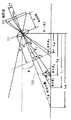
特許文献3に記載された従来の監視カメラ装置の人物と監視カメラとの水平距離の算出方法を図19に示す。図19において、111は監視カメラのカメラレンズ、112は監視カメラの撮影面、113はカメラによって撮影される人物である。fはカメラレンズ111の焦点距離、Hはカメラレンズ112の光軸中心までの高さ、θは水平線に対するカメラのチルト角、αはカメラレンズ112の垂直画角の1/2の角度である。人113はカメラレンズ111の光軸中心から水平距離でLjの位置にいるものとし、その位置を(i、j)とすると、撮影面112上での垂直方向の位置は、j・vとなる。ただし、v=(垂直撮像サイズ)/(垂直最大画素数)。
ここで、
d/p=v/f
jd/p=tanδj
ここで、jは−n、…、0、…、+nの整数。nは垂直最大画素数の1/2である。これらより
j(v/f)=tanδ
Lj=H/tan(θ+δj )
上の2つの式より、監視カメラから被写体の距離までは、
Lj=H/tan(θ+j・v/f)
と求められる。
設置条件を限定し、この算出式を簡単にする試みとしては下記の特許文献5に記載された技術がある。距離が分かれば、映った画像の大きさ(撮像時)の被写体の視野角から、更に身長も推定できる。
here,
d / p = v / f
jd / p = tanδj
Here, j is an integer of −n,..., 0,. n is 1/2 of the maximum number of vertical pixels. From these, j (v / f) = tan δ
Lj = H / tan (θ + δj)
From the above two formulas, the distance from the surveillance camera to the subject is
Lj = H / tan (θ + j · v / f)
Is required.
As an attempt to limit the installation conditions and simplify the calculation formula, there is a technique described in Patent Document 5 below. If the distance is known, the height can be further estimated from the viewing angle of the subject in the size of the image (when capturing).
しかしながら、特許文献4に示すように被写体像の大きさを推定するための基準スケールをフィルムに映し込む方法では、監視カメラにより撮像された監視映像の中から所望の監視対象のみの高さを表示することができないという問題点がある。また、被写体距離に基づいた撮影倍率から、被写体像の大きさを推定するための基準スケールを算出するために、撮影時に、画面内に設定された複数の焦点検出エリアの焦点検出結果の中からいずれかの焦点検出エリアを選択し、その焦点検出エリアの焦点結果に基づいて被写体距離を決める。そのため、ビデオレコーダに録画済の再生映像から、被写体への距離を推定するためには、ビデオレコーダの映像の他に、その録画映像の撮像時の焦点結果も保持し、参照できるようにしておかねばならない。 However, in the method of displaying a reference scale for estimating the size of a subject image on a film as shown in
また、特許文献3では、特許文献5に示すように、演算量を軽減させるために、光軸と水平との角度が画角の1/2になるように下方に向けて配置することが前提となっている。また、特許文献3に記載されるように、設置工事の際には、監視カメラの正確な高さHとチルト角θを把握する必要もある。監視映像全体の視野に、監視したい対象が入っているかどうかを、目視で合わせることが多く、チルト角については、把握されない場合が多い。 Moreover, in
そこで、本発明は上記の問題点に鑑み、監視カメラにより撮像された監視映像の中から所望の監視対象のみの高さを表示することができる監視装置及び監視方法を提供することを目的とする。
また、本発明は上記の問題点に鑑み、簡単な方法で、監視カメラにより撮像された監視映像の中から所望の監視対象のみの高さを表示することができる監視装置及び監視方法を提供することを目的とする。Therefore, in view of the above problems, the present invention has an object to provide a monitoring apparatus and a monitoring method capable of displaying the height of only a desired monitoring target from the monitoring video imaged by the monitoring camera. .
In addition, in view of the above-described problems, the present invention provides a monitoring apparatus and a monitoring method capable of displaying the height of only a desired monitoring target from monitoring images captured by a monitoring camera by a simple method. For the purpose.
本発明は上記目的を達成するために、監視カメラの撮像画像における所望の監視対象の上下方向の原寸法を算出し、この原寸法の数値情報を前記撮像画像と共に出力する監視装置であって、
前記撮像画像における前記所望の監視対象の上下各位置を指定するポインティング手段(22)と、
前記監視カメラの地上からの設置高情報と前記ポインティング手段で指定された上下各位置とに基づき前記監視対象の上下方向の原寸法を算出する原寸法算出手段(3)と、
前記ポインティング手段で指定された上下各位置に対応した大きさのスケール画像を前記原寸法算出手段で算出された原寸法の数値情報と共に生成するスケール画像生成手段(3)と、
前記生成されたスケール画像と前記原寸法の数値情報とを前記撮像画像に合成して出力する合成出力手段(3)とを、
備えたことを特徴とする。In order to achieve the above object, the present invention is a monitoring device that calculates an original size in a vertical direction of a desired monitoring target in a captured image of a monitoring camera, and outputs numerical information of the original size together with the captured image,
Pointing means (22) for designating the upper and lower positions of the desired monitoring target in the captured image;
Original dimension calculation means (3) for calculating the original dimension in the vertical direction of the monitoring target based on the installation height information of the monitoring camera from the ground and the vertical positions designated by the pointing means;
A scale image generating means (3) for generating a scale image having a size corresponding to each of the upper and lower positions designated by the pointing means together with numerical information of the original dimensions calculated by the original dimension calculating means;
Synthesis output means (3) for synthesizing and outputting the generated scale image and numerical information of the original dimensions to the captured image;
It is characterized by having.
また、本発明は上記目的を達成するために、監視カメラの撮像画像における所望の監視対象の上下方向の原寸法を算出し、この原寸法の数値情報を前記撮像画像と共に出力する監視装置であって、
前記撮像画像内の前記監視カメラからの距離の異なる複数箇所それぞれにおける特定のスケールの上下各位置を遠近法の消失点に基づき決定するスケール位置決定手段(3)と、
前記撮像画像における前記所望の監視対象の上下各位置を指定するポインティング手段(22)と、
前記スケール位置決定手段で決定された前記複数箇所それぞれにおける前記スケールの上下各位置と前記ポインティング手段で指定された上下各位置とに基づき前記監視対象の上下方向の原寸法を算出する原寸法算出手段(3)と、
前記ポインティング手段で指定された上下各位置に対応した大きさのスケール画像を前記原寸法算出手段で算出された原寸法の数値情報と共に生成するスケール画像生成手段(3)と、
前記生成されたスケール画像と前記原寸法の数値情報とを前記撮像画像に合成して出力する合成出力手段(3)とを、
備えたことを特徴とする。In order to achieve the above object, the present invention is a monitoring device that calculates an original vertical dimension of a desired monitoring target in a captured image of a monitoring camera and outputs numerical information of the original dimension together with the captured image. And
Scale position determining means (3) for determining each of the upper and lower positions of a specific scale at each of a plurality of locations at different distances from the monitoring camera in the captured image based on a vanishing point of perspective;
Pointing means (22) for designating the upper and lower positions of the desired monitoring target in the captured image;
Original dimension calculation means for calculating the original dimension in the vertical direction of the monitoring target based on the respective vertical positions of the scale determined by the scale position determination means and the vertical positions specified by the pointing means. (3) and
A scale image generating means (3) for generating a scale image having a size corresponding to each of the upper and lower positions designated by the pointing means together with numerical information of the original dimensions calculated by the original dimension calculating means;
Synthesis output means (3) for synthesizing and outputting the generated scale image and numerical information of the original dimensions to the captured image;
It is characterized by having.
また、本発明は上記目的を達成するために、監視カメラの撮像画像における所望の監視対象の上下方向の原寸法を算出し、この原寸法の数値情報を前記撮像画像と共に出力する監視方法であって、
前記撮像画像における前記所望の監視対象の上下各位置をポインティングデバイスによって指定するポインティングステップ(S3)と、
前記監視カメラの地上からの設置高情報と前記ポインティングステップにおいて指定された上下各位置とに基づき前記監視対象の上下方向の原寸法を算出する原寸法算出ステップ(S4)と、
前記ポインティングステップにおいて指定された上下各位置に対応した大きさのスケール画像を前記原寸法算出ステップにおいて算出された原寸法の数値情報と共に生成するスケール画像生成ステップ(S4)と、
前記生成されたスケール画像と前記原寸法の数値情報とを前記撮像画像に合成して出力する合成出力ステップ(S5)とを、
有したことを特徴とする。Further, in order to achieve the above object, the present invention is a monitoring method for calculating an original vertical dimension of a desired monitoring target in a captured image of a monitoring camera and outputting numerical information of the original dimension together with the captured image. And
A pointing step (S3) for designating the upper and lower positions of the desired monitoring target in the captured image with a pointing device;
An original dimension calculating step (S4) for calculating an original dimension in the vertical direction of the monitoring target based on the installation height information of the monitoring camera from the ground and the vertical positions designated in the pointing step;
A scale image generation step (S4) for generating a scale image having a size corresponding to each of the upper and lower positions designated in the pointing step together with numerical information of the original dimension calculated in the original dimension calculating step;
A combined output step (S5) of combining the generated scale image and the numerical information of the original dimensions with the captured image and outputting the combined image;
It is characterized by having.
また、本発明は上記目的を達成するために、監視カメラの撮像画像における所望の監視対象の上下方向の原寸法を算出し、この原寸法の数値情報を前記撮像画像と共に出力する監視方法であって、
前記撮像画像内の前記監視カメラからの距離の異なる複数箇所それぞれにおける特定のスケールの上下各位置を遠近法の消失点に基づき決定するスケール位置決定ステップ(S11〜S13)と、
前記撮像画像における前記所望の監視対象の上下各位置をポインティングデバイスによって指定するポインティングステップ(S14)と、
前記スケール位置決定ステップにおいて決定された前記複数箇所それぞれにおける前記スケールの上下各位置と前記ポインティングステップにおいて指定された上下各位置とに基づき前記監視対象の上下方向の原寸法を算出する原寸法算出ステップ(S15、S16)と、
前記ポインティングステップにおいて指定された上下各位置に対応した大きさのスケール画像を前記原寸法算出ステップにおいて算出された原寸法の数値情報と共に生成するスケール画像生成ステップ(S4)と、
前記生成されたスケール画像と前記原寸法の数値情報とを前記撮像画像に合成して出力する合成出力ステップ(S5)とを、
有したことを特徴とする。Further, in order to achieve the above object, the present invention is a monitoring method for calculating an original vertical dimension of a desired monitoring target in a captured image of a monitoring camera and outputting numerical information of the original dimension together with the captured image. And
A scale position determination step (S11 to S13) for determining the upper and lower positions of a specific scale at each of a plurality of locations at different distances from the monitoring camera in the captured image based on a vanishing point of perspective;
A pointing step (S14) of designating the upper and lower positions of the desired monitoring target in the captured image with a pointing device;
An original dimension calculating step of calculating an original dimension in the vertical direction of the monitoring target based on the upper and lower positions of the scale at each of the plurality of locations determined in the scale position determining step and the upper and lower positions specified in the pointing step. (S15, S16),
A scale image generation step (S4) for generating a scale image having a size corresponding to each of the upper and lower positions designated in the pointing step together with numerical information of the original dimension calculated in the original dimension calculating step;
A combined output step (S5) of combining the generated scale image and the numerical information of the original dimensions with the captured image and outputting the combined image;
It is characterized by having.
本発明によれば、ポインティング手段により指定された上下位置に基づいて監視対象の高さを表示するので、監視カメラにより撮像された監視映像の中から所望の監視対象のみの高さを表示することができる。また、監視画面上の各位置の上下方向のスケールを遠近法の消失点に基づいてあらかじめ算出するので、簡単な方法で、監視カメラにより撮像された監視映像の中から所望の監視対象のみの高さを表示することができる。すなわち、ポインタを、画面上の被測定対象物の位置に移動させると、被写体の実際の寸法を表す目盛りがスケールとなるが、これは、操作員の指示に従った位置にのみ表示される。撮影された映像に映る人物のうちの、容貌や服装、身長などの身体的特徴を具体的に把握したいと要求される人物にのみ適用される。同時に1つの画面に映っている他の、特に注目を要しない人物については、身長やその人物の位置などの情報は表示されることがないため、その余分な情報に視界を妨げられることはなくなる。 According to the present invention, since the height of the monitoring target is displayed based on the vertical position designated by the pointing means, the height of only the desired monitoring target is displayed from the monitoring video imaged by the monitoring camera. Can do. In addition, since the vertical scale of each position on the monitoring screen is calculated in advance based on the vanishing point of the perspective method, only a desired monitoring target is selected from the monitoring images captured by the monitoring camera by a simple method. Can be displayed. That is, when the pointer is moved to the position of the object to be measured on the screen, the scale indicating the actual dimension of the subject becomes the scale, but this is displayed only at the position according to the instruction of the operator. It applies only to those who are required to specifically grasp physical features such as appearance, clothes, and height among the people shown in the captured video. For other people who are on the screen at the same time and do not need special attention, information such as height and the position of the person will not be displayed, so the extra information will not obstruct the view. .
以下、図面を参照して本発明の実施の形態について説明する。
<第1の実施の形態>
図1は本発明に係る監視装置を適用した映像監視システムの一実施の形態を示すブロック図である。Embodiments of the present invention will be described below with reference to the drawings.
<First Embodiment>
FIG. 1 is a block diagram showing an embodiment of a video monitoring system to which a monitoring apparatus according to the present invention is applied.
図1に示す例では、監視カメラ1a〜1dで監視対象を撮影してモニタディスプレイ2a、2b(やハードコピー装置21)で表示することにより、警備員は監視カメラ1a〜1dで撮影された映像をモニタディスプレイ2a、2bで監視する。3は付加機能を実現する装置であり、複数の付加機能が必要な場合、複数の装置で構成されることも多い。例えば付加機能3は、監視カメラが複数台ある場合には、マトリックススイッチャ(複数の映像のうち、任意の映像のみを選択する装置)や画面分割ユニット(1画面を分割し、そこに複数の監視カメラの映像を同時に表示させる装置)で構成される。また、監視員が常駐できないような場合や、監視映像を記録として残したい場合は、付加機能3にビデオテープレコーダ31やディスクレコーダ32も用いる。操作卓22は付加機能3の制御(例えば複数のうちのどの映像を選ぶかの指示や、画面分割の状態の切り替え、レコーダの録画、再生、停止、早送りや巻き戻しなど)や、監視カメラ1a〜1dの遠隔制御(向きの制御やフォーカシング)のための、ユーザインタフェースである。操作卓22の例を図2に示す。 In the example shown in FIG. 1, the
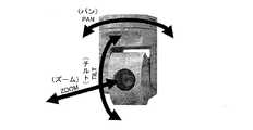
次に、監視カメラ1a〜1dの出力からの監視映像から、任意の被写体の上下方向の原寸法(被写体が直立している人物の場合、身長)を算出する方法を説明する。通常の操作において、警備員が監視映像に着目したい人物を見つけた場合、監視カメラがPTZ (PAN(パン)…左右、TILT(チルト)…上下、ZOOM(ズーム)…拡大の略)制御可能なカメラ(以下、「PTZカメラ」と記載;例を図3に示す)であれば、その人物が監視画面に大きく映るよう操作卓22からPTZ制御を行う。この操作は、自動化される場合も多い。PTZカメラの多くは、外部からの信号入力をトリガとして、あらかじめ設定された方向とズームを合わせる機能を持つ。万引防止センサや、自動販売機やパチンコ店の遊戯機器の内部もしくは近傍に設置されたセンサ(例えば機器のこじ開けセンサ)、あるいは窓の防犯センサなどから、異常を知らせる信号がある場合、その信号をPTZカメラに入力し、それをトリガとして、センサの位置に応じた視野にカメラが自動的に追従する。 Next, a method of calculating the original vertical dimension of an arbitrary subject (height in the case of an upright person) from the monitoring video from the outputs of the
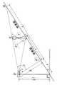
図4に示すように固定点P(地上高h)に設置されたカメラ1があるとき、人物A−A’が、カメラ1から地上におろした垂線と地表の交点P’からどれくらいの距離aを歩行しているかは、カメラの設置角や視野角などから∠APP’の角度αが分かれば、次式(1)で計算できる
a=h・tanα …(1)
また、人物の頭頂部とカメラを結ぶ線と、カメラから下ろした垂線のなす∠A’PP’の角度βが分かれば、人物の身長xも次式(2)で計算できる。
b=h・tanβ
h:b=x:b−a(∵△P’PB∽A’AB)
∴x=h・(b−a)/b
=h・(tanβ−tanα)/tanβ …(2)As shown in FIG. 4, when there is a
Also, if the angle β of ∠A'PP 'formed by a line connecting the head of the person and the camera and a perpendicular drawn from the camera is known, the person's height x can also be calculated by the following equation (2).
b = h · tanβ
h: b = x: ba (∵ΔP′PB∽A′AB)
∴x = h · (ba) / b
= H · (tanβ-tanα) / tanβ (2)
多くの場合、カメラの高さhは固定で、設置時に決められる。角度α、βはPTZカメラの制御状態で決まるので、それを把握すればよい。また、PTZ制御が不能なカメラ(以下、「固定カメラ」と記載)では、角度α、βは設置時に決まる。なお、角度α、βは、撮像板のサイズやレンズの視野(焦点距離)から算出可能である。特許文献3にそれが説明されているので、ここでは説明を省略する。 In many cases, the height h of the camera is fixed and is determined at the time of installation. Since the angles α and β are determined by the control state of the PTZ camera, it is only necessary to grasp them. In addition, in a camera that cannot perform PTZ control (hereinafter referred to as “fixed camera”), the angles α and β are determined at the time of installation. The angles α and β can be calculated from the size of the imaging plate and the field of view (focal length) of the lens. Since this is described in
本発明を実施する際に必要なカメラ1の構成のうち、PTZカメラの構成を図5に示す。撮像部11はカメラとしての撮像機能であり、映像信号18を出力する。PTZ制御機構12は外部からの制御信号15の指示に応じて、撮像部11の向きや、撮像部11のレンズのズームの状態を制御する。これが、PTZカメラとしての最低限の構成要素である。身長を知るには、(2)式の例では、角度α、βと高さhを把握しなければならない。これらは、PTZカメラそのものが設置された高さと傾き、そして、その内部で、撮像部11がどのような角度に制御され、その視野がどのようにズーミングされているかから把握できるので、それらの情報、すなわち、PTZ制御の状態とカメラ1の設置高の付加情報16を映像信号18に重畳して出力する。 Of the configuration of the
付加情報16を映像信号18に重畳する方法としては、例えばアナログテレビジョンの文字多重放送のように、映像信号18のモニタディスプレイには表示されない垂直帰線期間に付加情報16を重畳する方法。あるいは、映像信号18がJPEG方式のようなデジタル情報の場合、その規格に許容される拡張領域やコメント領域などに付加情報16を載せる方法もある。付加情報16が重畳された映像信号19は、ビデオテープレコーダ31やディスクレコーダ32(図1)に録画保存することもでき、その再生出力から付加情報16を取り出すことができれば、角度α、βとカメラ1の設置された高さhを、すなわち、任意の被写体の高さを知るためのゲージの表示に必要な情報が得られる。 A method of superimposing the
また、伝送路がTCP/IPのようなプロトコルによるものの場合、意図的に映像そのものに情報を重畳させるのではなく、付加情報16と映像信号18を、論理的に全く異なるコネクションを張って送受信することも可能である。
さらにまた、付加情報16を映像信号18に重畳せず、映像信号18のみがビデオテープレコーダ31又はディスクレコーダ32(図1)に録画保存される場合には、その映像情報の個々の時点と、付加情報16の個々の時点付けを行う手段が必要である。例えば、付加情報には、タイムスタンプも合わせ、何らかの記録手段に、カメラ1a〜1dに対応付けたファイル(file-1a〜file-1d…)に保持しておく。カメラ1cのある時点の付加情報16は、file-1cのその時点に対応するタイムスタンプを持つレコードを参照すればよい。Further, when the transmission path is based on a protocol such as TCP / IP, information is not intentionally superimposed on the video itself, but the
Furthermore, when the
ここまで、被写体の高さを知るために、PTZカメラを用い、(2)式のような三角関数を用いる方法を例に挙げ説明してきた。固定カメラの場合には、第2の実施の形態に記載の映像のパースペクティブに基づいた方法における定数pとy0を重畳してもよい。固定カメラの場合、PTZ制御信号15ならびにPTZ制御機構12は存在しないので、代わりに定数pとy0を保持するメモリをPTZ制御機構12の位置に持ってもよい。So far, in order to know the height of the subject, a method using a trigonometric function like equation (2) using a PTZ camera has been described as an example. In the case of a fixed camera, the constants p and y0 in the method based on the video perspective described in the second embodiment may be superimposed. In the case of a fixed camera, since the
映像信号18への付加情報の重畳をカメラに内蔵する例を説明してきているが、図6に示すように、既に設置済みのPTZカメラ1を利用する場合には、付加情報16の重畳は外部機構10で行うことになる。この図の例では、PTZカメラへ入力するPTZ制御信号15をトラップし、それを基にPTZ機構の状態を推定した結果を外部機構10内部のPTZ状態保持部13に保持する。その保持されている状態を付加情報16として映像信号18に重畳する。なお、三角関数を用いる方法やパースペクティブに基づいた方法、あるいは、ここに記載しない他の方法による情報が混在する場合には、先に説明した付加情報16や、あるいは定数pとy0などの情報の他に、情報の記載形式を識別するためのフォーマット識別子も併せて重畳してもよい。Although an example in which the superimposition of additional information on the
また、図4は便宜的に地面(床面)を水平に描いている。屋内環境では、床面が水平な場合が多いが、屋外の監視では、山の斜面や坂道など、地面が水平とは限らない。しかし、(2)式は、ほぼそのまま成り立つ。これについて、図7を用いて説明する。地面が傾きθで傾いている場合、地表と垂直をなすような線分P−P’(長さh)を考えれば、P’−A間の距離aについては図4と同様に計算できる。hとxの関係は(2)式の通り。△PP”P’∽△AA’A”なので、A地点の人物の身長x’は、
x’=h’・(tanβ−tanα)/tanβ
となる。FIG. 4 depicts the ground (floor surface) horizontally for convenience. In an indoor environment, the floor is often horizontal, but in outdoor monitoring, the ground such as mountain slopes and slopes is not always horizontal. However, equation (2) holds almost as it is. This will be described with reference to FIG. When the ground is inclined at an inclination θ, the distance a between P′-A can be calculated in the same manner as in FIG. 4 in consideration of a line segment PP ′ (length h) perpendicular to the ground surface. The relationship between h and x is as in equation (2). △ PP "P'∽ △ AA'A", so the height x 'of the person at point A is
x ′ = h ′ · (tan β−tan α) / tan β
It becomes.
カメラ1の設置高(図4のh、図7のh’)は、ほとんどの場合、設置工事のときに決まり、既知であるものとする。例えば、エレベータ三脚、クレーン雲台などによりカメラの設置高が変わることは、監視映像の場合、ほとんどない。もし、カメラの設置高を変える場合は、電子的な遠隔制御に頼ることが多く、その高さは、その遠隔制御のための情報から推定できる。 It is assumed that the installation height (h in FIG. 4 and h ′ in FIG. 7) of the
また、角度βは、図8において、カメラのチルト角をθとすれば、
β=θ+δ
=θ+tan-1(p/f)
となり、チルト角θと、撮像板5上での見かけ上の大きさp、レンズ4の焦点距離fから求められる。角度αについても同様にして求められる。Further, the angle β can be obtained by assuming that the tilt angle of the camera is θ in FIG.
β = θ + δ
= Θ + tan-1 (p / f)
Is obtained from the tilt angle θ, the apparent size p on the imaging plate 5, and the focal length f of the
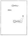
さて、監視対象となるのが、多くの人が集まる公共の場である場合、監視映像には、図9に示すように大勢の人物が映ることになる。身体的特徴として、身長に着目すると、本当に知りたいのは、そこに映る全員の身長ではなく、特定の人物100の身長である。そこで、本発明では、監視画像を表示する際に、操作者が図10(a)に示すように監視対象の上端にポインタ26を移動してマウスボタンを押し、次いで図10(b)に示すようにマウスボタンを押したままポインタ26を移動して刻々変わる時点でのポインタ位置と図10(a)に示す位置を対角線とするボックスを表示する。そして、操作者が図10(c)に示すように監視対象の下端にポインタ26を移動してマウスボタンを離すと、ボックスの高さを計算し、図10(d)に示すように、計算した高さ(身長)を示す数字(165cm)をスケールとして監視対象のボックスの隣に表示する。また、数字を表示する代わりに、図11に示すように身長ゲージを表示するようにしてもよい。身長の算出は、既に述べた方法や、他の既知の方法を用いてもよい。また、図12は目盛りの下端がポインタ26を兼ねている例を示す。 Now, if the subject of monitoring is a public place where many people gather, a large number of people will appear in the surveillance video as shown in FIG. Focusing on height as a physical feature, what we really want to know is not the height of all the people in the picture but the height of a
図13は、ステップ4において図10(d)に示すスケールや図11に示す身長ゲージが表示されるまでの、一連の流れである。この処理は、図1の操作卓22に設けられているボタンやスイッチ類により起動される。また、この処理がパーソナルコンピュータ上で実施される場合は、キーボードやマウスの操作により起動されてもよい。この例では、ステップS1で、カメラの設置高とPTZ状態を把握しているが、既に述べたとおり、第2の実施の形態(後述)に記載の映像のパースペクティブに基づいた方法における定数pとy0の把握でもよい。ステップS2は、操作卓22のジョイスティックや、マウスなどのポインティングデバイスでの入力を促すプロンプティングで、例えば図10のように、対象物の上端と下端を把握できるような入力を促す。上端と下端は、オペレータの手作業でポインティングデバイスから指示してもよいが、動体検出やオブジェクト認識など、既知の手段で個々の人物を映像から切り出すことが可能な場合、その人物のどこか一部を選択するだけで、その全身を把握するような、ユーザインタフェースも構築可能になる。FIG. 13 shows a series of flows until the scale shown in FIG. 10D and the height gauge shown in FIG. 11 are displayed in
ステップS3で入力操作が有りと判断されると、ステップS4へ進む。ステップS4では、図4に示した距離aが分かれば、その位置に存在する被写体を映す撮像板の個々の画素について、それぞれの実際の大きさを推定できるので、それに基づきステップS5において身長を示す数字やゲージを表示させる。図4の演算内容が少し異なるが、基本的には同じフローで処理される。なお、これらは、図1の付加機能3で処理されるが、パーソナルコンピュータやワークステーションなどで構成されてもよく、監視映像そのものと、身長ゲージやカーソルの表示方法については、既知の一般的な方法を使えばよい。 If it is determined in step S3 that there is an input operation, the process proceeds to step S4. In step S4, if the distance a shown in FIG. 4 is known, the actual size of each pixel on the imaging board showing the subject present at that position can be estimated. Based on this, the height is shown in step S5. Display numbers and gauges. Although the calculation contents in FIG. 4 are slightly different, the processing is basically performed in the same flow. These are processed by the
また、以上の説明は、被写体が人物であり、その身長を把握することを例に挙げて説明してきたが、これは、平らな床面に置かれた任意の物体の高さと読み替えることができる。また、撮影された画像の画素が正方形である場合は、被写体を構成する個々の画素の高さ方向の実際の寸法と、横方向の実際の寸法は一致するので、高さだけでなく幅の把握と表示も可能である。撮影された画像の画素が正方形でない場合には、その画素の縦横比を単純に勘案し、幅を求めることができる。 In the above description, the subject is a person and the height is grasped as an example, but this can be read as the height of an arbitrary object placed on a flat floor. . In addition, when the pixels of the captured image are square, the actual dimensions in the height direction and the actual dimensions in the horizontal direction of the individual pixels constituting the subject coincide with each other. It can also be grasped and displayed. If the pixel of the captured image is not square, the width can be obtained simply by taking the aspect ratio of the pixel into consideration.
<第2の実施の形態>
図14は監視映像を模式的に描いた例を示し、図14を用いて本発明の第2の実施の形態の原理を説明する。この図において、遠い箇所と近い箇所の2箇所に全く同じ身長の人物が映っているものとする。2箇所の人物と床面の接点、すなわち、足が床についている点の画面上の垂直座標をyaとyb、画面上での見かけ上のこの人物の身長をha、hb(例えば単位はピクセル、あるいは走査線本数)、この画面のパース (パースペクティブ=透視法:遠近法)の消失点(必ずしも撮影された監視映像の画面上にあるとは限らない)の垂直座標をy0とすると、
ha:hb=(ya−y0):(yb−y0) …(3)
と、線形に比例する。この人物が、任意の点に移動したとき、監視映像画面上で、足を付けている点の垂直座標をyとしたとき、見かけ上の画面上での身長hは、
h=p・(y−y0) …(4)
ここで、pとy0は定数。<Second Embodiment>
FIG. 14 shows an example in which a surveillance video is schematically drawn. The principle of the second embodiment of the present invention will be described with reference to FIG. In this figure, it is assumed that persons with exactly the same height are shown in two places, a distant place and a close place. Contact person and the floor of the two positions, i.e., ya and yb a vertical coordinate on the screen at the point where the legs are attached to the floor, the height of the person ha apparent on the screen, hb (e.g. The unit is pixel, or the number of scanning lines), and the vertical coordinate of the vanishing point (perspective = perspective method: perspective method) of this screen (not necessarily on the screen of the captured surveillance video) is y0 Then
ha : hb = (ya −y0 ) :( yb −y0 ) (3)
And linearly proportional. When this person moves to an arbitrary point, when the vertical coordinate of the point on the monitoring video screen is y, the apparent height h on the screen is
h = p · (y−y0 ) (4)
Here, p and y0 are constants.
ここで、カメラの位置(設置高)や向き(パンやチルトの角度)、ズームの状態(レンズの焦点距離)が、通常の運用状態では変化せず固定的に利用される監視カメラを、特に「固定カメラ」と呼ぶ。すなわち、固定カメラが撮影する映像のパースは、設置時に決められる。パースが固定されれば、定数pとy0も一意に決まる。この2つの定数p、y0を、固定カメラのパースを決め終えた時点で求める作業を、ここでは「キャリブレーション」と呼ぶことにする。Here, a surveillance camera that is fixedly used without changing the camera position (installation height), orientation (pan and tilt angles), and zoom status (lens focal length) in normal operating conditions, especially Called “Fixed Camera”. That is, the perspective of the video captured by the fixed camera is determined at the time of installation. If the perspective is fixed, the constants p and y0 are also uniquely determined. The operation for obtaining these two constants p and y0 when the fixed camera perspective has been determined will be referred to herein as “calibration”.
キャリブレーション、すなわち、定数pとy0を求める手順を説明する。図15(a)に示すように、まず、任意の地点に、一定の長さの棒24aを床面に垂直に設置し、図14における監視映像画面の座標yaと見かけ上の長さhaを測る。次に図15(b)に示すように、棒の設置箇所を変え(棒24b)、図14における監視映像画面で座標ybと見かけ上の長さhbを測る。
(3)、(4)の関係から、定数pとy0は、
p=(ha−hb)/(ya−yb) …(5)
y0=ya−ha/p
=yb−hb/p
と求められる。Calibration, that is, a procedure for obtaining constants p and y0 will be described. Figure 15 (a), the first, an arbitrary point, placed vertically a certain length of the
From the relationship between (3) and (4), the constants p and y0 are
p = (h a -h b) / (y a -y b) ... (5)
y 0 = y a -h a / p
= Yb -hb / p
Is required.
この例では、2地点での測定を基準にして定数pとy0を把握する方法を記したが、例えば測定点を増やし、直線回帰分析のような統計的手法により、定数pとy0を把握してもよい。上述したキャリブレーションを、監視画像を目視しながらの手作業で行うことは原理的には可能であるが、現実的でない。そこで、監視画像を表示する際に、監視画像に合わせて、図15に示すようにマウスやジョイスティックなどのポインティングデバイスの操作により任意の点を指すポインタ25を表示し、そのポインタ位置から監視画像上のya、ybと、見かけ上の長さha、hbを測るような、インタラクティビティをもったソフトウェア処理を介することが考えられる。In this example, the method of grasping the constants p and y0 based on the measurement at two points is described. However, for example, the constants p and y0 are obtained by a statistical method such as linear regression analysis by increasing the number of measurement points. You may grasp. Although it is possible in principle to perform the above-described calibration manually while viewing the monitoring image, it is not practical. Therefore, when displaying a monitoring image, a
図16、図17を参照してこのキャリブレーションのソフトウェア処理について説明する。このソフトウェア処理は呼び出されると、ステップS11において監視画面と共に、図15に示すように、yaの入力を促すプロンプティングメッセージと共にポインタ25を表示させ、次いでステップS12では図17に詳しく示すキャリブレーション入力サブルーチンを呼び出す。このサブルーチンでは、オペレータ(設置工事者や保守作業員など)が任意の地点に一定の長さの棒24aを床面に垂直に設置し(ステップS21)、監視映像画面の座標yaを測るために、ポインティングデバイスの操作によりポインタ25を棒24aの下端(ポインタ25a)に移動し、ポインティングデバイスのボタン(例えばマウスボタン)を操作する(ステップS22)。これにより、キャリブレーションのソフトウェア処理は座標y=yaを把握できる(ステップS23)。The calibration software processing will be described with reference to FIGS. When this software process is called,a
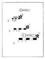
このソフトウェアは、次に、棒24aの上端(ポインタ25b)にポインタ25を移動しボタン操作を行う旨のメッセージをプロンプティングした後に(ステップS24)、オペレータからの操作待ち状態に入る(ステップS25)。オペレータがポインタ25を棒24aの上端(ポインタ25b)に移動し、ボタン操作を行うと、キャリブレーションのソフトウェア処理は、入力された座標y’と、既に把握している座標y=yaから長さh=y’−y(ha=y’−ya)を把握できる(ステップS27、図16のステップS13)。次に棒24bについて同様の処理を繰り返し(図16のステップS14、S15)、棒24bの座標ybから長さhbをキャリブレーションのソフトウェア処理に把握させる(ステップS16)。キャリブレーションのソフトウェア処理は、(5)式や直線回帰分析などにより定数pとy0を求めることができる(ステップS17)。(3)式の演算をソフトウェア手段により実現する例について説明する。ソフトウェア手段は、例えば図18に模式的に示したような監視画像と監視画像上にポインタ26を表示する際に、ポインタ26の垂直座標を(3)式にあてはめ、画面上の見かけ上の長さhで身長ゲージを表示する。これは、キャリブレーションの際に、実際の高さが165cmの棒を使っていれば、それと同じ長さに相当するスケールとなる。Next, the software prompts a message to move the
上記処理により、図18に示すように、オペレータは、異なる距離に位置する複数の人物から、身長を推定したい人物の足元にポインタ26、26’、26”を合わせることにより、身長の推定の補助となるスケールを画面表示として得ることができる。図16に示したゲージが、実際の高さ165cmでキャリブレートされているとき、監視カメラ1の光軸が水平に近い状態に設置されていれば、例えば175cmのゲージは、(5)式の結果を170/165倍することで、近似的に表すことができる。これにより、図14に示すように、身長を推定したい人物の足元にポインタ26を合わせることで、スケールを表示することもできる。 By the above processing, as shown in FIG. 18, the operator assists the height estimation by aligning the
ここで、監視カメラ1の光軸が床面に垂直に近くなるほど、近似精度は劣化し、実用的ではなくなる。そこで、上記説明では、図15の棒24aの下端(ポインタ25a)と上端(ポインタ25b)、そして棒24bの下端(ポインタ26a)と上端(ポインタ26b)のみの画面上の座標を測ったが、さらに、棒24aの中間位置(ポインタ25c、25d)を測ることとする。例えば床面からの高さを、上端のポインタ25bが175cm、中間位置のポインタ25cが170cm、ポインタ25dが165cmとする。まず、同様に、ポインタ25a、25bとポインタ26a、26bから、高さ175cmでの定数pと消失点の垂直座標y0が求められる。Here, the closer the optical axis of the
次に、高さ170cmでの定数p'を求めるために、ポインタ25cの垂直座標を測る。方法は、上記説明と同様の手段を用いることができ、ポインタ25cの座標ya'と長さha'を把握できる。既に、消失点y0は分かっており、そこでの被写体は、見かけ上、大きさが0となるため、(5)式を変形し、高さ170cmでの定数p'は、
p’=(ha'−0)/(ya'−y0)
=ha'/(ya'−y0)
となり、ポインタ25cに相当する棒24bの位置の測定は不要である。ポインタ25dについても同様である。このようにして、監視カメラ1の光軸が床面に対し、垂直に近くなっても、図18に示すように実用的なゲージを表示できる。Next, in order to obtain a constant p ′ at a height of 170 cm, the vertical coordinate of the
p '= (h a' -0 ) / (y a '-y 0)
= H a '/ (y a ' -y 0)
Thus, it is not necessary to measure the position of the
上記説明では、オペレータの操作により、画面上に、監視カメラ1が捉えた任意の人物の身長を推定する手段を記したが、オペレータの介在なく、あるいは、画面上への表示をすることなく、これらの処理を機械化することも可能である。例えば、パターン抽出/認識手段により、映像の中の人物を機械的に抽出し、その人物の身長を把握したい場合にも、本発明のアルゴリズムを応用できる。例えばキャリブレーションの段階では、それに用いる固定長の棒を、特徴的な色彩、等間隔の赤と白で塗りわけた棒をオペレータが設置する。撮像された映像上に、赤と白が縦に連なった状態を、パターン抽出/認識手段が機械的に検出でき、その座標データを把握できれば、前記した一連のポインタ表示とボタン操作の一連の手順を省くことができる。オペレータは機械からの指示に従い、キャリブレーションのための棒状の基準を、任意の少なくとも2点に移動しながら設置すればよい。もちろん、この場合、少なくとも2本のキャリブレーション用の棒を用意し、同時にその座標と高さを把握することも可能であろう。また、身長の把握時には、例えば、前後のフレーム(映画のコマに相当)を比較することで、動きのある領域と、その画面上の座標を知ることができる。その座標を基に、動きのある物体の高さを類推することが可能である。もちろん、高さを測ろうとする被写体の自動検出手段は、その他のパターン認識手法に頼ってもよい。 In the above description, the means for estimating the height of an arbitrary person captured by the
1、1a〜1d 監視カメラ
2a、2b モニタディスプレイ
3 付加機能
4 レンズ
5 撮像板
10 外部機構
11 撮像部
12 PTZ制御機構
13 PTZ状態保持部
15 PTZ制御信号
16 付加情報
18、19 映像信号
21 ハードコピー装置
22 操作卓
24a、24b 棒
25、25a〜25d、26、26’、26”、26a、26b ポインタ
31 ビデオテープレコーダ
32 ディスクレコーダ
100 特定の人物
DESCRIPTION OF
Claims (4)
Translated fromJapanese前記撮像画像における前記所望の監視対象の上下各位置を指定するポインティング手段と、
前記監視カメラの地上からの設置高情報と前記ポインティング手段で指定された上下各位置とに基づき前記監視対象の上下方向の原寸法を算出する原寸法算出手段と、
前記ポインティング手段で指定された上下各位置に対応した大きさのスケール画像を前記原寸法算出手段で算出された原寸法の数値情報と共に生成するスケール画像生成手段と、
前記生成されたスケール画像と前記原寸法の数値情報とを前記撮像画像に合成して出力する合成出力手段とを、
備えた構成の監視装置。A monitoring device that calculates an original vertical dimension of a desired monitoring target in a captured image of a monitoring camera and outputs numerical information of the original dimension together with the captured image,
Pointing means for designating the upper and lower positions of the desired monitoring target in the captured image;
An original dimension calculating means for calculating an original dimension in the vertical direction of the monitoring target based on the installation height information from the ground of the monitoring camera and the vertical positions designated by the pointing means;
A scale image generating means for generating a scale image having a size corresponding to each of the upper and lower positions designated by the pointing means together with numerical information of the original dimensions calculated by the original dimension calculating means;
A synthesized output means for synthesizing and outputting the generated scale image and the numerical information of the original dimension to the captured image;
A monitoring device with a configuration provided.
前記撮像画像内の前記監視カメラからの距離の異なる複数箇所それぞれにおける特定のスケールの上下各位置を遠近法の消失点に基づき決定するスケール位置決定手段と、
前記撮像画像における前記所望の監視対象の上下各位置を指定するポインティング手段と、
前記スケール位置決定手段で決定された前記複数箇所それぞれにおける前記スケールの上下各位置と前記ポインティング手段で指定された上下各位置とに基づき前記監視対象の上下方向の原寸法を算出する原寸法算出手段と、
前記ポインティング手段で指定された上下各位置に対応した大きさのスケール画像を前記原寸法算出手段で算出された原寸法の数値情報と共に生成するスケール画像生成手段と、
前記生成されたスケール画像と前記原寸法の数値情報とを前記撮像画像に合成して出力する合成出力手段とを、
備えた構成の監視装置。A monitoring device that calculates an original vertical dimension of a desired monitoring target in a captured image of a monitoring camera and outputs numerical information of the original dimension together with the captured image,
Scale position determining means for determining the upper and lower positions of a specific scale at each of a plurality of locations at different distances from the monitoring camera in the captured image, based on a vanishing point of perspective;
Pointing means for designating the upper and lower positions of the desired monitoring target in the captured image;
Original dimension calculation means for calculating the original dimension in the vertical direction of the monitoring target based on the respective vertical positions of the scale determined by the scale position determination means and the vertical positions specified by the pointing means. When,
A scale image generating means for generating a scale image having a size corresponding to each of the upper and lower positions designated by the pointing means together with numerical information of the original dimensions calculated by the original dimension calculating means;
A synthesized output means for synthesizing and outputting the generated scale image and the numerical information of the original dimension to the captured image;
A monitoring device with a configuration provided.
前記撮像画像における前記所望の監視対象の上下各位置をポインティングデバイスによって指定するポインティングステップと、
前記監視カメラの地上からの設置高情報と前記ポインティングステップにおいて指定された上下各位置とに基づき前記監視対象の上下方向の原寸法を算出する原寸法算出ステップと、
前記ポインティングステップにおいて指定された上下各位置に対応した大きさのスケール画像を前記原寸法算出ステップにおいて算出された原寸法の数値情報と共に生成するスケール画像生成ステップと、
前記生成されたスケール画像と前記原寸法の数値情報とを前記撮像画像に合成して出力する合成出力ステップとを、
有した監視方法。A monitoring method for calculating an original vertical dimension of a desired monitoring target in a captured image of a monitoring camera and outputting numerical information of the original dimension together with the captured image,
A pointing step of designating the upper and lower positions of the desired monitoring target in the captured image by a pointing device;
An original dimension calculating step of calculating an original dimension in the vertical direction of the monitoring target based on the installation height information from the ground of the monitoring camera and the vertical positions specified in the pointing step;
A scale image generation step for generating a scale image of a size corresponding to each of the upper and lower positions designated in the pointing step together with numerical information of the original dimension calculated in the original dimension calculation step;
A combined output step of combining the generated scale image and the numerical information of the original dimension with the captured image and outputting the combined image;
The monitoring method we had.
前記撮像画像内の前記監視カメラからの距離の異なる複数箇所それぞれにおける特定のスケールの上下各位置を遠近法の消失点に基づき決定するスケール位置決定ステップと、
前記撮像画像における前記所望の監視対象の上下各位置をポインティングデバイスによって指定するポインティングステップと、
前記スケール位置決定ステップにおいて決定された前記複数箇所それぞれにおける前記スケールの上下各位置と前記ポインティングステップにおいて指定された上下各位置とに基づき前記監視対象の上下方向の原寸法を算出する原寸法算出ステップと、
前記ポインティングステップにおいて指定された上下各位置に対応した大きさのスケール画像を前記原寸法算出ステップにおいて算出された原寸法の数値情報と共に生成するスケール画像生成ステップと、
前記生成されたスケール画像と前記原寸法の数値情報とを前記撮像画像に合成して出力する合成出力ステップとを、
有した監視方法。
A monitoring method for calculating an original vertical dimension of a desired monitoring target in a captured image of a monitoring camera and outputting numerical information of the original dimension together with the captured image,
A scale position determining step for determining each position above and below a specific scale at each of a plurality of locations at different distances from the monitoring camera in the captured image, based on a vanishing point of perspective;
A pointing step of designating the upper and lower positions of the desired monitoring target in the captured image by a pointing device;
An original dimension calculating step of calculating an original dimension in the vertical direction of the monitoring target based on the upper and lower positions of the scale at each of the plurality of locations determined in the scale position determining step and the upper and lower positions specified in the pointing step. When,
A scale image generation step for generating a scale image of a size corresponding to each of the upper and lower positions designated in the pointing step together with numerical information of the original dimension calculated in the original dimension calculation step;
A combined output step of combining the generated scale image and the numerical information of the original dimension with the captured image and outputting the combined image;
The monitoring method we had.
Priority Applications (1)
| Application Number | Priority Date | Filing Date | Title |
|---|---|---|---|
| JP2006026324AJP2007208745A (en) | 2006-02-02 | 2006-02-02 | Monitoring device and monitoring method |
Applications Claiming Priority (1)
| Application Number | Priority Date | Filing Date | Title |
|---|---|---|---|
| JP2006026324AJP2007208745A (en) | 2006-02-02 | 2006-02-02 | Monitoring device and monitoring method |
Publications (1)
| Publication Number | Publication Date |
|---|---|
| JP2007208745Atrue JP2007208745A (en) | 2007-08-16 |
Family
ID=38487782
Family Applications (1)
| Application Number | Title | Priority Date | Filing Date |
|---|---|---|---|
| JP2006026324AWithdrawnJP2007208745A (en) | 2006-02-02 | 2006-02-02 | Monitoring device and monitoring method |
Country Status (1)
| Country | Link |
|---|---|
| JP (1) | JP2007208745A (en) |
Cited By (8)
| Publication number | Priority date | Publication date | Assignee | Title |
|---|---|---|---|---|
| CN100582654C (en)* | 2008-09-25 | 2010-01-20 | 广州广电运通金融电子股份有限公司 | Height measuring method and its measuring device |
| JP2010244090A (en)* | 2009-03-31 | 2010-10-28 | Sogo Keibi Hosho Co Ltd | Person information extraction device, person information extraction method, and person information extraction program |
| CN103164203A (en)* | 2011-12-15 | 2013-06-19 | 阿里巴巴集团控股有限公司 | Element adjusting method and device |
| KR20150021350A (en)* | 2013-08-20 | 2015-03-02 | 삼성테크윈 주식회사 | Apparatus and method for processing image |
| KR20160092338A (en)* | 2015-01-27 | 2016-08-04 | 한화테크윈 주식회사 | Method for detecting motion, camera and surveillance system adopting the method |
| KR101851823B1 (en)* | 2014-07-31 | 2018-04-25 | 경성대학교 산학협력단 | Method for classifying children and adult bt using head and body height in images |
| US11580661B2 (en)* | 2020-11-23 | 2023-02-14 | Motorola Solutions, Inc. | Device, method and system for estimating elevation in images from camera devices |
| CN118200479A (en)* | 2024-02-23 | 2024-06-14 | 苏州一际智能科技有限公司 | Method and device for determining target object distance based on monitoring video |
- 2006
- 2006-02-02JPJP2006026324Apatent/JP2007208745A/ennot_activeWithdrawn
Cited By (10)
| Publication number | Priority date | Publication date | Assignee | Title |
|---|---|---|---|---|
| CN100582654C (en)* | 2008-09-25 | 2010-01-20 | 广州广电运通金融电子股份有限公司 | Height measuring method and its measuring device |
| JP2010244090A (en)* | 2009-03-31 | 2010-10-28 | Sogo Keibi Hosho Co Ltd | Person information extraction device, person information extraction method, and person information extraction program |
| CN103164203A (en)* | 2011-12-15 | 2013-06-19 | 阿里巴巴集团控股有限公司 | Element adjusting method and device |
| KR20150021350A (en)* | 2013-08-20 | 2015-03-02 | 삼성테크윈 주식회사 | Apparatus and method for processing image |
| KR102066938B1 (en)* | 2013-08-20 | 2020-01-16 | 한화테크윈 주식회사 | Apparatus and method for processing image |
| KR101851823B1 (en)* | 2014-07-31 | 2018-04-25 | 경성대학교 산학협력단 | Method for classifying children and adult bt using head and body height in images |
| KR20160092338A (en)* | 2015-01-27 | 2016-08-04 | 한화테크윈 주식회사 | Method for detecting motion, camera and surveillance system adopting the method |
| KR102391852B1 (en) | 2015-01-27 | 2022-04-28 | 한화테크윈 주식회사 | Method for detecting motion, camera and surveillance system adopting the method |
| US11580661B2 (en)* | 2020-11-23 | 2023-02-14 | Motorola Solutions, Inc. | Device, method and system for estimating elevation in images from camera devices |
| CN118200479A (en)* | 2024-02-23 | 2024-06-14 | 苏州一际智能科技有限公司 | Method and device for determining target object distance based on monitoring video |
Similar Documents
| Publication | Publication Date | Title |
|---|---|---|
| JP2007208745A (en) | Monitoring device and monitoring method | |
| JP6313270B2 (en) | Monitoring method and device | |
| JP3727954B2 (en) | Imaging device | |
| US8471930B2 (en) | Image capturing apparatus and image processing apparatus | |
| JP4912117B2 (en) | Imaging device with tracking function | |
| JP3265893B2 (en) | Image display device | |
| TWI314008B (en) | Imaging device and method, computer program product on computer-readable medium, and imaging system | |
| CN114040169A (en) | Information processing apparatus, information processing method, and storage medium | |
| KR101695249B1 (en) | Method and system for presenting security image | |
| US20090237508A1 (en) | Method and apparatus for providing immersive surveillance | |
| TW201216712A (en) | Image capturing device and image monitoring method using the image capturing device | |
| TW201209762A (en) | Method of tracking images automatically | |
| JP6705102B2 (en) | Imaging device installation support device, imaging device installation support method, and video recording/reproducing device | |
| JP2012057974A (en) | Photographing object size estimation device, photographic object size estimation method and program therefor | |
| US8174571B2 (en) | Apparatus for processing images, apparatus for processing reproduced images, method of processing images, and method of processing reproduced images | |
| JP2016092693A (en) | IMAGING DEVICE, IMAGING DEVICE CONTROL METHOD, AND PROGRAM | |
| JP2008281385A (en) | Image processing device | |
| JP2003158664A (en) | Camera control device | |
| JP2009182640A (en) | Intercom device | |
| JPH0793558A (en) | Image monitoring device | |
| KR20180013264A (en) | Image display apparatus having weighted thumbnail | |
| JP2019186727A (en) | Imaging device, method for controlling the same, program, and imaging system | |
| JP3875199B2 (en) | Imaging device | |
| JP3858018B2 (en) | Video surveillance system | |
| JP2005236724A (en) | Imaging device and motion detection method |
Legal Events
| Date | Code | Title | Description |
|---|---|---|---|
| A300 | Withdrawal of application because of no request for examination | Free format text:JAPANESE INTERMEDIATE CODE: A300 Effective date:20090407 |