JP2007208656A - Portable terminal and information reading-out program - Google Patents
Portable terminal and information reading-out programDownload PDFInfo
- Publication number
- JP2007208656A JP2007208656AJP2006024992AJP2006024992AJP2007208656AJP 2007208656 AJP2007208656 AJP 2007208656AJP 2006024992 AJP2006024992 AJP 2006024992AJP 2006024992 AJP2006024992 AJP 2006024992AJP 2007208656 AJP2007208656 AJP 2007208656A
- Authority
- JP
- Japan
- Prior art keywords
- sim card
- storage medium
- holding
- unit
- control unit
- Prior art date
- Legal status (The legal status is an assumption and is not a legal conclusion. Google has not performed a legal analysis and makes no representation as to the accuracy of the status listed.)
- Pending
Links
Images


Landscapes
- Mobile Radio Communication Systems (AREA)
- Telephone Function (AREA)
Abstract
Description
Translated fromJapanese本発明は、記憶媒体が記憶している情報を読み出す読み出し手段を備えた携帯端末および携帯端末に搭載される情報読み出しプログラムに関する。 The present invention relates to a portable terminal provided with a reading unit that reads information stored in a storage medium, and an information reading program installed in the portable terminal.
携帯電話会社が発行する、契約者情報を記録したICカードであるSIM(Subscriber Identity Module)カードを装着するSIMカードコネクタ(SIMカードスロットともいう。)を有する携帯電話機がある。 There is a mobile phone having a SIM card connector (also referred to as a SIM card slot) to which a SIM (Subscriber Identity Module) card, which is an IC card in which contractor information is recorded, is issued by a mobile phone company.
そのような携帯電話機は、一般に、1つのSIMカードコネクタを有しているため、ユーザは1枚のSIMカードが記憶している電話番号を使用する。 Such mobile phones generally have one SIM card connector, so the user uses the phone number stored on one SIM card.
ユーザが、1枚のSIMカードで複数の携帯電話機を使用する場合には、ユーザが使用する各携帯電話機にそのSIMカードを装着して、携帯電話機を使用する。 When a user uses a plurality of mobile phones with one SIM card, the SIM card is attached to each mobile phone used by the user and the mobile phone is used.
また、ユーザが、例えば、個人契約のSIMカードと、会社契約のSIMカードとを所持している場合、ユーザは、2台の携帯電話機を使用して2つの電話番号を使い分けることができる。しかし、携帯電話機を2台持ち歩かなければならず、また、電話帳登録等を2台の携帯電話機のそれぞれに行わなければならないため、不便である。 For example, when the user has a SIM card with a personal contract and a SIM card with a company contract, the user can use two mobile numbers using two mobile phones. However, it is inconvenient because two mobile phones must be carried around, and phone book registration and the like must be performed for each of the two mobile phones.
なお、特許文献1には、2つのSIMカードを保持するソケットを有し、ユーザがソケットを回転させて、1つのSIMカードコネクタにソケットが保持するSIMカードの一方を装着することができる携帯電話機について記載されている。 Patent Document 1 discloses a mobile phone that has a socket for holding two SIM cards, and a user can mount one of the SIM cards held by the socket on one SIM card connector by rotating the socket. Is described.
特許文献2には、形式の異なるSIMカードを装着する複数のSIMカードコネクタを有する無線構成体について記載されている。
特許文献1に記載されている携帯電話機では、使用するSIMカードを切り替える場合に、ユーザがソケットを回転させる等の操作が必要であるが、そのような操作を行わずに、使用するSIMカードを切り替えられることが好ましい。 In the mobile phone described in Patent Document 1, when the SIM card to be used is switched, the user needs to perform an operation such as rotating the socket, but the SIM card to be used is not performed without performing such an operation. It is preferable to be switched.
また、複数のSIMカードを装着している場合には、どのSIMカードが記憶している情報にもとづく動作を行うのかをユーザが認識できることが好ましい。 Further, when a plurality of SIM cards are attached, it is preferable that the user can recognize which SIM card performs the operation based on the information stored therein.
そこで、本発明は、複数の記憶媒体を保持し、保持している記憶媒体を使い分ける携帯端末、および携帯端末に搭載される情報読み出しプログラムを提供することを目的とする。 Therefore, an object of the present invention is to provide a mobile terminal that holds a plurality of storage media, uses the stored storage media properly, and an information read program installed in the mobile terminal.
また、本発明は、複数の記憶媒体を保持し、保持している記憶媒体を使い分け、どの記憶媒体を使用しているのかをユーザに容易に認識させることができる携帯端末、および携帯端末に搭載される情報読み出しプログラムを提供することを目的とする。 In addition, the present invention holds a plurality of storage media, uses the stored storage media properly, and allows the user to easily recognize which storage medium is used, and is mounted on the mobile terminal It is an object to provide an information reading program.
本発明による携帯端末は、記憶媒体が記憶している情報を読み出す読み出し手段を備えた携帯端末であって、一の記憶媒体を保持する複数の保持手段と、読み出し手段と、保持手段が保持している記憶媒体とを接続する接続手段と、接続手段に、一の保持手段が保持している記憶媒体と読み出し手段とを接続させる制御手段とを備えたことを特徴とする。 A portable terminal according to the present invention is a portable terminal provided with a reading unit that reads information stored in a storage medium, and includes a plurality of holding units that hold one storage medium, a reading unit, and a holding unit. Connecting means for connecting to the storage medium, and control means for connecting the storage medium held by one holding means and the reading means to the connecting means.
制御手段は、接続手段を介して各保持手段に所定の信号を出力し、接続手段を介して保持手段が保持している記憶媒体から信号に応答する信号が入力された場合に、記憶媒体を保持している保持手段が、記憶媒体を保持していることを認識してもよい。 The control means outputs a predetermined signal to each holding means via the connection means, and when a signal in response to the signal is input from the storage medium held by the holding means via the connection means, the control means You may recognize that the holding | maintenance means currently hold | maintains the storage medium.
ユーザからの指示を入力する操作手段を含み、制御手段は、複数の保持手段が記憶媒体を保持している場合に、読み出し手段が情報を読み出す記憶媒体を操作手段に入力された指示に従って決定し、接続手段に、読み出すことを決定した記憶媒体を保持している保持手段と読み出し手段とを接続させてもよい。 The control means includes an operation means for inputting an instruction from the user, and the control means determines a storage medium from which the reading means reads information when the plurality of holding means hold the storage medium according to the instruction input to the operation means. The connecting means may be connected to the holding means holding the storage medium determined to be read and the reading means.
情報を表示する表示手段を含み、制御手段は、複数の保持手段が記憶媒体を保持している場合に、読み出し手段が情報を読み出す記憶媒体をユーザに選択させる画面を表示手段に表示させてもよい。 Including a display unit that displays information, and the control unit may cause the display unit to display a screen that allows the reading unit to select a storage medium from which the information is read when the plurality of holding units hold the storage medium. Good.
制御手段は、表示手段に、読み出し手段が情報を読み出す記憶媒体を示す画面を表示させてもよい。 The control unit may cause the display unit to display a screen indicating a storage medium from which the reading unit reads information.
情報を記憶する記憶手段を含み、制御手段は、読み出し手段が情報を読み出す記憶媒体を示す情報を、記憶手段に記憶させてもよい。 The control means may include storage means for storing information, and the control means may cause the storage means to store information indicating a storage medium from which the reading means reads information.
本発明による情報読み出しプログラムは、記憶媒体が記憶している情報を読み出す読み出し手段と、一の記憶媒体を保持する複数の保持手段と備えた携帯端末に搭載される情報読み出しプログラムであって、コンピュータに、一の保持手段が保持している記憶媒体と読み出し手段とを接続させる接続処理と、各保持手段に所定の信号を出力し、保持手段が保持している記憶媒体から信号に応答する信号が入力された場合に、記憶媒体を保持している保持手段が、記憶媒体を保持していることを認識する認識処理とを実行させることを特徴とする。 An information reading program according to the present invention is an information reading program mounted on a portable terminal provided with a reading means for reading information stored in a storage medium and a plurality of holding means for holding one storage medium, In addition, a connection process for connecting the storage medium held by one holding means and the reading means, and a signal that outputs a predetermined signal to each holding means and responds to the signal from the storage medium held by the holding means Is input, the holding means holding the storage medium executes recognition processing for recognizing that the storage medium is held.
本発明によれば、複数の保持手段がそれぞれ保持している記憶媒体が記憶している情報を使い分けることができる。 According to the present invention, it is possible to selectively use information stored in storage media respectively held by a plurality of holding means.
制御手段に、出力した所定の信号に対する応答が入力された場合に、保持手段が記憶媒体を保持していることを認識するように構成されている場合には、制御手段は、記憶媒体を保持している保持手段を認識することができる。 When the control means is configured to recognize that the holding means holds the storage medium when a response to the output predetermined signal is input, the control means holds the storage medium. The holding means can be recognized.
複数の保持手段が記憶媒体を保持している場合に、読み出し手段が情報を読み出す記憶媒体をユーザに入力された指示に従って決定するように構成されている場合には、ユーザの指示に応じて、情報を読み出す記憶媒体を決定することができる。 When the plurality of holding means hold the storage medium, when the reading means is configured to determine the storage medium from which information is read according to the instruction input by the user, according to the user's instruction, A storage medium from which information is read can be determined.
また、情報を読み出す記憶媒体をユーザに選択させる画面を表示手段に表示させるように構成されている場合には、ユーザは、画面を確認して情報を読み出す記憶媒体を決定することができる。 When the display unit is configured to display a screen that allows the user to select a storage medium from which information is to be read, the user can check the screen and determine a storage medium from which the information is read.
表示手段が、読み出し手段が情報を読み出す記憶媒体を示す画面を表示するように構成されている場合には、ユーザは、読み出し手段が情報を読み出す記憶媒体を確認することができる。 When the display unit is configured to display a screen indicating the storage medium from which the reading unit reads information, the user can check the storage medium from which the reading unit reads information.
実施の形態1.
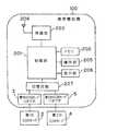
本発明の第1の実施の形態について、図面を参照して説明する。図1は、本発明による携帯端末の第1の実施の形態の一構成例を示すブロック図である。なお、ここでは、携帯端末の一例として、携帯電話機100を例にして説明する。Embodiment 1 FIG.
A first embodiment of the present invention will be described with reference to the drawings. FIG. 1 is a block diagram showing a configuration example of a first embodiment of a mobile terminal according to the present invention. Here, a
携帯電話機100は、アンテナ204を介して情報を送受信する無線部203と、情報を記憶するメモリ(記憶手段)202と、ユーザが指示を入力する操作部(操作手段)205と、情報を表示する表示部(表示手段)206と、SIMカード(記憶媒体)を装着(保持)する第1のSIMカードコネクタ(保持手段)3および第2のSIMカードコネクタ(保持手段)5と、使用するSIMカードコネクタを切り替える切替回路(接続手段)207と、携帯電話機100の全体を制御する制御部(読み出し手段、制御手段)201とを含む。 The
制御部201は、例えば、CPUによって実現される。無線部203は、アンテナ204を介して、携帯電話基地局に音声データや通信に必要な情報を搬送波にのせて送信したり、携帯電話基地局から音声データや通信に必要な情報を受信したりする。 The
以下、第1のSIMカードコネクタ3に装着されるSIMカードを第1のSIMカード2として説明し、第2のSIMカードコネクタ5に装着されるSIMカードを第2のSIMカード4として説明する。第1のSIMカード2と第2のSIMカード4とは、例えば、同一の形式のSIMカードである。 Hereinafter, the SIM card attached to the first
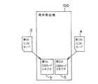
図2は、携帯電話機100がSIMカードを装着する場合を示す説明図である。図2に示す例では、第1のSIMカードコネクタ3に第1のSIMカード2が装着され、第2のSIMカードコネクタ5に第2のSIMカード4が装着される。 FIG. 2 is an explanatory diagram showing a case where the
図3は、携帯電話機100とSIMカードとの電気的接続を示す説明図である。各SIMカードには、電源入力端子であるVSIM端子、リセット信号入力端子であるRESET端子、クロック信号入力端子であるCLK端子、およびデータを入出力するDATA端子が設けられている。なお、図3に示す例では、VSIM端子をVSIMと示し、RESET端子をRESETと示し、CLK端子をCLKと示し、DATA端子をDATAと示している。 FIG. 3 is an explanatory diagram showing electrical connection between the
制御部201には、電源制御信号出力端子であるVSIM_cont端子、リセット信号出力端子であるRESET端子、クロック信号出力端子であるCLK端子、データを入出力するDATA端子、および切替回路207を制御する切替信号出力端子であるSIM_SEL端子が設けられている。 The
制御部201に設けられているRESET端子、CLK端子、DATA端子、およびSIM_SEL端子は、切替回路207に接続されている。VSIM_cont端子は、各SIMカードに電力を供給するレギュレータ305に接続されている。レギュレータ305は、制御部201が出力した電源制御信号に従って、切替回路207を介して各SIMカードに電力を供給する。 A RESET terminal, a CLK terminal, a DATA terminal, and a SIM_SEL terminal provided in the
切替回路207は、レギュレータ305が供給する電力の出力先を切り替える電力スイッチ301、制御部201が出力したリセット信号の出力先を切り替えるリセット信号スイッチ302、制御部201が出力したクロック信号の出力先を切り替えるクロック信号スイッチ303、および制御部201が入出力するデータの入出力先を切り替えるデータスイッチ304を含む。 The
なお、リセット信号スイッチ302、およびクロック信号スイッチ303は、制御部201が出力した切替信号に従って、制御部201が出力した各信号の出力先を、第1のSIMカードコネクタ3にするのか、または第2のSIMカードコネクタ5にするのかを切り替える。 Note that the
また、電力スイッチ301は、制御部201が出力した切替信号に従って、レギュレータ305が供給する電力の出力先を、第1のSIMカードコネクタ3にするのか、または第2のSIMカードコネクタ5にするのかを切り替える。 Further, according to the switching signal output from the
データスイッチ304は、制御部201が出力した切替信号に従って、制御部201が入出力するデータの入出力先を、第1のSIMカードコネクタ3にするのか、または第2のSIMカードコネクタ5にするのかを切り替える。 The
なお、携帯電話機100は、コンピュータに、一のSIMカードコネクタが保持(装着)しているSIMカードと制御手段201とを接続させる接続処理と、各SIMカードコネクタに所定の信号を出力し、SIMカードコネクタが保持しているSIMカードから信号に応答する信号が入力された場合に、SIMカードを保持しているSIMカードコネクタが、SIMカードを保持していることを認識する認識処理とを実行させるための情報読み出しプログラムを搭載している。 Note that the
次に、本発明の第1の実施の形態の動作について、図面を参照して説明する。図4は、本発明の第1の実施の形態の動作を説明するフローチャートである。 Next, the operation of the first exemplary embodiment of the present invention will be described with reference to the drawings. FIG. 4 is a flowchart for explaining the operation of the first embodiment of the present invention.
操作部205が電源オン操作された場合に(ステップS101)、制御部201は、第1のSIMカード2と通信を行うために、各信号、電力、およびデータが第1のSIMカードコネクタ3に出力されるように切替回路207が含む各スイッチを制御する切替信号を、SIM_SEL端子から出力する。 When the
切替回路207は、電力スイッチ301、リセット信号スイッチ302、クロック信号スイッチ303、およびデータスイッチ304を、各信号、電力、およびデータが第1のSIMカードコネクタ3に出力されるように切り替える。 The
また、制御部201は、第1のSIMカード2に電力を供給するために、レギュレータ305に電力の供給を指示する電源制御信号を、VSIM_cont端子から出力する。 Further, the
レギュレータ305は、電力の供給を指示する電源制御信号が入力された場合に、電力の供給を開始する。レギュレータ305は、切替回路207の電力スイッチ301、および第1のSIMカードコネクタ3を介して、第1のSIMカード2のVSIM端子に電圧を加える。 The
制御部201は、RESET端子からリセット信号を出力する。出力されたリセット信号は、切替回路207のリセット信号スイッチ302、および第1のSIMカードコネクタ3を介して、第1のSIMカード2のRESET端子に入力される。 The
制御部201は、CLK端子からクロック信号を出力する。出力されたクロック信号は、切替回路207のクロック信号スイッチ303、および第1のSIMカードコネクタ3を介して、第1のSIMカード2のCLK端子に入力される。 The
第1のSIMカード2が、RESET端子に入力されたリセット信号に応答するデータを、DATA端子から出力した場合に、出力されたデータは、第1のSIMカードコネクタ3、および切替回路207のデータスイッチ304を介して、制御部201のDATA端子に入力される。 When the
制御部201は、第1のSIMカード2が出力したデータがDATA端子に入力された場合に、第1のSIMカードコネクタ3が第1のSIMカード2を装着していることを認識する(ステップS102のY)。制御部201は、第1のSIMカード2が出力したデータがDATA端子に入力されない場合に、第1のSIMカードコネクタ3が第1のSIMカード2を装着していないことを認識する(ステップS102のN)。 When the data output from the
制御部201は、第2のSIMカード4と通信を行うために、各信号、電力、およびデータが第2のSIMカードコネクタ5に出力されるように切替回路207が含む各スイッチを制御する切替信号を、SIM_SEL端子から出力する。 The
切替回路207は、電力スイッチ301、リセット信号スイッチ302、クロック信号スイッチ303、およびデータスイッチ304を、各信号、電力、およびデータが第2のSIMカードコネクタ5に出力されるように切り替える。 The
また、制御部201は、第2のSIMカード4に電力を供給するために、レギュレータ305に電力の供給を指示する電源制御信号を、VSIM_cont端子から出力する。 Further, the
レギュレータ305は、電力の供給を指示する電源制御信号が入力された場合に、電力の供給を開始する。レギュレータ305は、切替回路207の電力スイッチ301、および第2のSIMカードコネクタ5を介して、第2のSIMカード4のVSIM端子に電圧を加える。 The
制御部201は、RESET端子からリセット信号を出力する。出力されたリセット信号は、切替回路207のリセット信号スイッチ302、および第2のSIMカードコネクタ5を介して、第2のSIMカード4のRESET端子に入力される。 The
制御部201は、CLK端子からクロック信号を出力する。出力されたクロック信号は、切替回路207のクロック信号スイッチ303、および第2のSIMカードコネクタ5を介して、第2のSIMカード4のCLK端子に入力される。 The
第2のSIMカード4が、RESET端子に入力されたリセット信号に応答するデータを、DATA端子から出力した場合に、出力されたデータは、第2のSIMカードコネクタ5、および切替回路207のデータスイッチ304を介して、制御部201のDATA端子に入力される。 When the
制御部201は、第2のSIMカード4が出力したデータがDATA端子に入力された場合に、第2のSIMカードコネクタ5が第2のSIMカード4を装着していることを認識する(ステップS103およびS104のY)。制御部201は、第2のSIMカード4が出力したデータがDATA端子に入力されない場合に、第2のSIMカードコネクタ5が第2のSIMカード4を装着していないことを認識する(ステップS103およびS104のN)。 When the data output from the
制御部201は、第1のSIMカードコネクタ3が第1のSIMカード2を装着していることを認識し、第2のSIMカードコネクタ5が第2のSIMカード4を装着していることを認識した場合に(ステップS103のY)、第1のSIMカード2と第2のSIMカード4とのうち、どちらのSIMカードを使用するのかをユーザに選択させる画面を、表示部206に表示させ、使用するSIMカードをユーザに選択させる(ステップS105)。 The
操作部205に、第1のSIMカード2を使用する指示が入力された場合(ステップS106のY)、および前述したステップS103で、制御部201が、第2のSIMカードコネクタ5が第2のSIMカード4を装着していないことを認識した場合(ステップS103のN)に、制御部201は、第1のSIMカード2を使用することを示す画面を、表示部206に表示させる(ステップS107)。 When an instruction to use the
そして、制御部201は、メモリ202に、第1のSIMカードコネクタ3が装着している第1のSIMカード2を使用することを記憶させる(ステップS108)。制御部201は、第1のSIMカード2が記憶している情報を読み出し、読み出した情報にもとづいて、携帯電話機100の各部を制御し、電源オン後の所定の動作を行う(ステップS109)。 And the
ステップS106で、操作部205に、第2のSIMカード4を使用する指示が入力された場合(ステップS106のN)、および前述したステップS104で、第2のSIMカードコネクタ5が第2のSIMカード4を装着していることを認識した場合(ステップS104のY)に、制御部201は、第2のSIMカード4を使用することを示す画面を、表示部206に表示させる(ステップS110)。 When an instruction to use the
そして、制御部201は、メモリ202に、第2のSIMカードコネクタ5が装着している第2のSIMカード4を使用することを記憶させる(ステップS111)。制御部201は、第2のSIMカード4が記憶している情報を読み出し、読み出した情報にもとづいて、携帯電話機100の各部を制御し、電源オン後の所定の動作を行う(ステップS109)。 And the
前述したステップS104で、第2のSIMカードコネクタ5が第2のSIMカード4を装着していないことを認識した場合(ステップS104のN)に、制御部201は、SIMカードがSIMカードコネクタに装着されていないことを示す画面を、表示部206に表示させる(ステップS112)。 When the second
そして、制御部201は、メモリ202に、SIMカードを使用しないことを記憶させる(ステップS113)。制御部201は、SIMカードを使用せずに携帯電話機100の各部を制御し、電源オン後の所定の動作を行う(ステップS109)。 And the
以上に述べたように、この実施の形態によれば、2つのSIMカードコネクタと、切替回路207とを備えたので、携帯電話機100は、第1のSIMカード2が装着されている状態、第2のSIMカード4が装着されている状態、第1のSIMカード2と第2のSIMカード4とが装着されている状態、およびSIMカードが装着されていない状態に応じて動作することができる。 As described above, according to this embodiment, since the
特に、第1のSIMカード2と第2のSIMカード4とが装着されている状態で、携帯電話機100は、ユーザが選択したSIMカードが記憶している情報にもとづいて動作することができる。 In particular, in a state where the
また、この実施の形態によれば、表示部206が、使用するSIMカードを示す画面を表示するため、ユーザが、誤ったSIMカードを使用することを防ぐことができる。 Further, according to this embodiment, since the
実施の形態2.
本発明の第2の実施の形態について、図面を参照して説明する。図5は、本発明による携帯端末の第2の実施の形態の一構成例を示すブロック図である。なお、ここでは、携帯端末の一例として、携帯電話機200を例にして説明する。
A second embodiment of the present invention will be described with reference to the drawings. FIG. 5 is a block diagram showing a configuration example of the second embodiment of the portable terminal according to the present invention. Here, a
第2の実施の形態の携帯電話機200は、SIMカードを装着する第3のSIMカードコネクタ7と、使用するSIMカードコネクタを切り替える第1の切替回路208および第2の切替回路209とを有する点が第1の実施の形態の携帯電話機100と異なる。第2の実施の形態の携帯電話機200のその他の構成要素は、第1の実施の形態の携帯電話機100と同様なため、図1と同じ符号を付し、説明を省略する。 The
図6は、携帯電話機200がSIMカードを装着する場合を示す説明図である。図6に示す例では、第1のSIMカードコネクタ3に第1のSIMカード2が装着され、第2のSIMカードコネクタ5に第2のSIMカード4が装着され、第3のSIMカードコネクタ7に第3のSIMカード6が装着される。 FIG. 6 is an explanatory diagram showing a case where the
以下、第3のSIMカードコネクタ7に装着されるSIMカードを第3のSIMカード6として説明する。第1のSIMカード2と第2のSIMカード4と第3のSIMカード6とは、例えば、同一の形式のSIMカードである。 Hereinafter, the SIM card mounted on the third
図7は、携帯電話機200とSIMカードとの電気的接続を示す説明図である。第2の実施の形態において各SIMカードが備える端子は、第1の実施の形態における各SIMカードが備える端子と同様なため、説明を省略する。 FIG. 7 is an explanatory diagram showing electrical connection between the
第2の実施の形態の制御部201は、電源制御信号出力端子であるVSIM_cont端子、リセット信号出力端子であるRESET端子、クロック信号出力端子であるCLK端子、データを入出力するDATA端子、第1の切替回路208を制御する切替信号出力端子である第1のSIM_SEL端子、および第2の切替回路209を制御する切替信号出力端子である第2のSIM_SEL端子が設けられている。 The
制御部201に設けられているRESET端子、CLK端子、第1のSIM_SEL端子、およびDATA端子は、第1の切替回路208に接続されている。第2のSIM_SEL端子は、第2の切替回路209に接続されている。VSIM_cont端子は、各SIMカードに電力を供給するレギュレータ305に接続されている。レギュレータ305は、制御部201が出力した電源制御信号に従って、第1の切替回路208、または第1の切替回路208と第2の切替回路209とを介して各SIMカードに電力を供給する。 A RESET terminal, a CLK terminal, a first SIM_SEL terminal, and a DATA terminal provided in the
第1の切替回路208は、レギュレータ305が供給する電力の出力先を、第2の切替回路209と第3のSIMカードコネクタ7とで切り替える第1の電力スイッチ311、制御部201が出力したリセット信号の出力先を、第2の切替回路209と第3のSIMカードコネクタ7とで切り替える第1のリセット信号スイッチ312、制御部201が出力したクロック信号の出力先を、第2の切替回路209と第3のSIMカードコネクタ7とで切り替える第1のクロック信号スイッチ313、および制御部201が入出力するデータの入出力先を、第2の切替回路209と第3のSIMカードコネクタ7とで切り替える第1のデータスイッチ314を含む。 The
なお、第1のリセット信号スイッチ312、および第1のクロック信号スイッチ313は、制御部201が出力した切替信号に従って、制御部201が出力した各信号の出力先を、第2の切替回路209にするのか、または第3のSIMカードコネクタ7にするのかを切り替える。 Note that the first
また、第1の電力スイッチ311は、制御部201が出力した切替信号に従って、レギュレータ305が供給する電力の出力先を、第2の切替回路209にするのか、または第3のSIMカードコネクタ7にするのかを切り替える。 Further, the
第1のデータスイッチ314は、制御部201が出力した切替信号に従って、制御部201が入出力するデータの入出力先を、第2の切替回路209にするのか、または第3のSIMカードコネクタ7にするのかを切り替える。 The
第2の切替回路209は、第1の切替回路208を介してレギュレータ305が供給する電力の出力先を、第1のSIMカードコネクタ3と第2のSIMカードコネクタ5とで切り替える第2の電力スイッチ321、制御部201が第1の切替回路208を介して出力したリセット信号の出力先を、第1のSIMカードコネクタ3と第2のSIMカードコネクタ5とで切り替える第2のリセット信号スイッチ322、制御部201が第1の切替回路208を介して出力したクロック信号の出力先を、第1のSIMカードコネクタ3と第2のSIMカードコネクタ5とで切り替える第2のクロック信号スイッチ323、および制御部201が第1の切替回路208を介して入出力するデータの入出力先を、第1のSIMカードコネクタ3と第2のSIMカードコネクタ5とで切り替える第2のデータスイッチ324を含む。 The
なお、第2のリセット信号スイッチ322、および第2のクロック信号スイッチ323は、制御部201が出力した切替信号に従って、第1の切替回路208を介して制御部201が出力した各信号の出力先を、第1のSIMカードコネクタ3にするのか、または第2のSIMカードコネクタ5にするのかを切り替える。 Note that the second
また、第2の電力スイッチ321は、制御部201が出力した切替信号に従って、第1の切替回路208を介してレギュレータ305が供給する電力の出力先を、第1のSIMカードコネクタ3にするのか、または第2のSIMカードコネクタ5にするのかを切り替える。 Whether the
第2のデータスイッチ324は、制御部201が出力した切替信号に従って、第1の切替回路208を介して制御部201が入出力するデータの入出力先を、第1のSIMカードコネクタ3にするのか、または第2のSIMカードコネクタ5にするのかを切り替える。 The
次に、本発明の第2の実施の形態の動作について、図面を参照して説明する。図8は、本発明の第2の実施の形態の動作を説明するフローチャートである。 Next, the operation of the second exemplary embodiment of the present invention will be described with reference to the drawings. FIG. 8 is a flowchart for explaining the operation of the second embodiment of the present invention.
操作部205が電源オン操作されると(ステップS201)、制御部201は、第1のSIMカード2と通信を行うために、各信号、電力、およびデータが第1のSIMカードコネクタ3に出力されるように第1の切替回路208および第2の切替回路209が含む各スイッチを制御する切替信号を、第1のSIM_SEL端子および第2のSIM_SEL端子から出力する。 When the
第1の切替回路208は、第1の電力スイッチ311、第1のリセット信号スイッチ312、第1のクロック信号スイッチ313、および第1のデータスイッチ314を、各信号、電力、およびデータが第2の切替回路209に出力されるように切り替える。 The
第2の切替回路209は、第2の電力スイッチ321、第2のリセット信号スイッチ322、第2のクロック信号スイッチ323、および第2のデータスイッチ324を、各信号、電力、およびデータが第1のSIMカードコネクタ3に出力されるように切り替える。 The
また、制御部201は、第1のSIMカード2に電力を供給するために、レギュレータ305に電力の供給を指示する電源制御信号を、VSIM_cont端子から出力する。 Further, the
レギュレータ305は、電力の供給を指示する電源制御信号が入力された場合に、電力の供給を開始する。レギュレータ305は、第1の切替回路208の第1の電力スイッチ311、第2の切替回路209の第2の電力スイッチ321、および第1のSIMカードコネクタ3を介して、第1のSIMカード2のVSIM端子に電圧を加える。 The
制御部201は、RESET端子からリセット信号を出力する。出力されたリセット信号は、第1の切替回路208の第1のリセット信号スイッチ312、第2の切替回路209の第2のリセット信号スイッチ322、および第1のSIMカードコネクタ3を介して、第1のSIMカード2のRESET端子に入力される。 The
制御部201は、CLK端子からクロック信号を出力する。出力されたクロック信号は、第1の切替回路208の第1のクロック信号スイッチ313、第2の切替回路209の第2のクロック信号スイッチ323、および第1のSIMカードコネクタ3を介して、第1のSIMカード2のCLK端子に入力される。 The
第1のSIMカード2が、RESET端子に入力されたリセット信号に応答するデータを、DATA端子から出力した場合に、出力されたデータは、第1のSIMカードコネクタ3、第2の切替回路209の第2のデータスイッチ324、および第1の切替回路208の第1のデータスイッチ314を介して、制御部201のDATA端子に入力される。 When the
制御部201は、第1のSIMカード2が出力したデータがDATA端子に入力された場合に、第1のSIMカードコネクタ3が第1のSIMカード2を装着していることを認識する(ステップS202のY)。制御部201は、第1のSIMカード2が出力したデータがDATA端子に入力されない場合に、第1のSIMカードコネクタ3が第1のSIMカード2を装着していないことを認識する(ステップS202のN)。 When the data output from the
制御部201は、第2のSIMカード4と通信を行うために、各信号、電力、およびデータが第2のSIMカードコネクタ5に出力されるように第1の切替回路208および第2の切替回路209が含む各スイッチを制御する切替信号を、第1のSIM_SEL端子および第2のSIM_SEL端子から出力する。 In order to communicate with the
第1の切替回路208は、第1の電力スイッチ311、第1のリセット信号スイッチ312、第1のクロック信号スイッチ313、および第1のデータスイッチ314を、各信号、電力、およびデータが第2の切替回路209に出力されるように切り替える。 The
第2の切替回路209は、第2の電力スイッチ321、第2のリセット信号スイッチ322、第2のクロック信号スイッチ323、および第2のデータスイッチ324を、各信号、電力、およびデータが第2のSIMカードコネクタ5に出力されるように切り替える。 The
また、制御部201は、第2のSIMカード4に電力を供給するために、レギュレータ305に電力の供給を指示する電源制御信号を、VSIM_cont端子から出力する。 Further, the
レギュレータ305は、電力の供給を指示する電源制御信号が入力された場合に、電力の供給を開始する。レギュレータ305は、第1の切替回路208の第1の電力スイッチ311、第2の切替回路209の第2の電力スイッチ321、および第2のSIMカードコネクタ5を介して、第2のSIMカード4のVSIM端子に電圧を加える。 The
制御部201は、RESET端子からリセット信号を出力する。出力されたリセット信号は、第1の切替回路208の第1のリセット信号スイッチ312、第2の切替回路209の第2のリセット信号スイッチ322、および第2のSIMカードコネクタ5を介して、第2のSIMカード4のRESET端子に入力される。 The
制御部201は、CLK端子からクロック信号を出力する。出力されたクロック信号は、第1の切替回路208のクロック信号スイッチ313、第2の切替回路209のクロック信号スイッチ323、および第2のSIMカードコネクタ5を介して、第2のSIMカード4のCLK端子に入力される。 The
第2のSIMカード4が、RESET端子に入力されたリセット信号に応答するデータを、DATA端子から出力した場合に、出力されたデータは、第2のSIMカードコネクタ5、第2の切替回路209のデータスイッチ324、および第1の切替回路208のデータスイッチ314を介して、制御部201のDATA端子に入力される。 When the
制御部201は、第2のSIMカード4が出力したデータがDATA端子に入力された場合に、第2のSIMカードコネクタ5が第2のSIMカード4を装着していることを認識する(ステップS203およびS204のY)。制御部201は、第2のSIMカード4が出力したデータがDATA端子に入力されない場合に、第2のSIMカードコネクタ5が第2のSIMカード4を装着していないことを認識する(ステップS203およびS204のN)。 When the data output from the
制御部201は、第3のSIMカード6と通信を行うために、各信号、電力、およびデータが第3のSIMカードコネクタ7に出力されるように第1の切替回路208が含む各スイッチを制御する切替信号を、第1のSIM_SEL端子から出力する。 In order to communicate with the
第1の切替回路208は、第1の電力スイッチ311、第1のリセット信号スイッチ312、第1のクロック信号スイッチ313、および第1のデータスイッチ314を、各信号、電力、およびデータが第3のSIMカードコネクタ7に出力されるように切り替える。 The
また、制御部201は、第3のSIMカード6に電力を供給するために、レギュレータ305に電力の供給を指示する電源制御信号を、VSIM_cont端子から出力する。 Further, the
レギュレータ305は、電力の供給を指示する電源制御信号が入力された場合に、電力の供給を開始する。レギュレータ305は、第1の切替回路208の第1の電力スイッチ311、および第3のSIMカードコネクタ7を介して、第3のSIMカード6のVSIM端子に電圧を加える。 The
制御部201は、RESET端子からリセット信号を出力する。出力されたリセット信号は、第1の切替回路208の第1のリセット信号スイッチ312、および第3のSIMカードコネクタ7を介して、第3のSIMカード6のRESET端子に入力される。 The
制御部201は、CLK端子からクロック信号を出力する。出力されたクロック信号は、第1の切替回路208のクロック信号スイッチ313、および第3のSIMカードコネクタ7を介して、第3のSIMカード6のCLK端子に入力される。 The
第3のSIMカード6が、RESET端子に入力されたリセット信号に応答するデータを、DATA端子から出力した場合に、出力されたデータは、第3のSIMカードコネクタ7、および第1の切替回路208のデータスイッチ314を介して、制御部201のDATA端子に入力される。 When the
制御部201は、第3のSIMカード6が出力したデータがDATA端子に入力された場合に、第3のSIMカードコネクタ7が第3のSIMカード6を装着していることを認識する(ステップS205、S206、S207、およびS208のY)。制御部201は、第3のSIMカード6が出力したデータがDATA端子に入力されない場合に、第3のSIMカードコネクタ7が第3のSIMカード6を装着していないことを認識する(ステップS205、S206、S207、およびS208のN)。 When the data output from the
制御部201は、第1のSIMカードコネクタ3が第1のSIMカード2を装着していることを認識し、第2のSIMカードコネクタ5が第2のSIMカード4を装着していることを認識し、第3のSIMカードコネクタ7が第3のSIMカード6を装着していることを認識した場合に(ステップS205のY)、第1のSIMカード2と第2のSIMカード4と第3のSIMカード6とのうち、どのSIMカードを使用するのかをユーザに選択させる画面を、表示部206に表示させ、使用するSIMカードをユーザに選択させる(ステップS209)。 The
制御部201は、第1のSIMカードコネクタ3が第1のSIMカード2を装着していることを認識し、第2のSIMカードコネクタ5が第2のSIMカード4を装着していることを認識した場合に(ステップS205のN)、第1のSIMカード2と第2のSIMカード4とのうち、どちらのSIMカードを使用するのかをユーザに選択させる画面を、表示部206に表示させ、使用するSIMカードをユーザに選択させる(ステップS210)。 The
制御部201は、第1のSIMカードコネクタ3が第1のSIMカード2を装着していることを認識し、第3のSIMカードコネクタ7が第3のSIMカード6を装着していることを認識した場合に(ステップS206のY)、第1のSIMカード2と第3のSIMカード6とのうち、どちらのSIMカードを使用するのかをユーザに選択させる画面を、表示部206に表示させ、使用するSIMカードをユーザに選択させる(ステップS211)。 The
操作部205に、第1のSIMカード2を使用する指示が入力された場合(ステップS212、S213、およびS214のY)、および前述したステップS206で、制御部201が、第3のSIMカードコネクタ7が第3のSIMカード6を装着していないことを認識した場合(ステップS206のN)に、制御部201は、第1のSIMカード2を使用することを示す画面を、表示部206に表示させる(ステップS215)。 When an instruction to use the
そして、制御部201は、メモリ202に、第1のSIMカードコネクタ3が装着している第1のSIMカード2を使用することを記憶させる(ステップS216)。制御部201は、第1のSIMカード2が記憶している情報を読み出し、読み出した情報にもとづいて、携帯電話機200の各部を制御し、電源オン後の所定の動作を行う(ステップS217)。 And the
制御部201は、第2のSIMカードコネクタ5が第2のSIMカード4を装着していることを認識し、第3のSIMカードコネクタ7が第3のSIMカード6を装着していることを認識した場合に(ステップS207のY)、第2のSIMカード4と第3のSIMカード6とのうち、どちらのSIMカードを使用するのかをユーザに選択させる画面を、表示部206に表示させ、使用するSIMカードをユーザに選択させる(ステップS218)。 The
操作部205に、第2のSIMカード4を使用する指示が入力された場合(ステップS212がNでありS219がY、S213のN、およびS219のY)、および前述したステップS207で、制御部201が、第3のSIMカードコネクタ7が第3のSIMカード6を装着していないことを認識した場合(ステップS207のN)に、制御部201は、第2のSIMカード4を使用することを示す画面を、表示部206に表示させる(ステップS220)。 When an instruction to use the
そして、制御部201は、メモリ202に、第2のSIMカードコネクタ5が装着している第2のSIMカード4を使用することを記憶させる(ステップS221)。制御部201は、第2のSIMカード4が記憶している情報を読み出し、読み出した情報にもとづいて、携帯電話機200の各部を制御し、電源オン後の所定の動作を行う(ステップS217)。 And the
操作部205に、第3のSIMカード6を使用する指示が入力された場合(ステップS214のN、およびS219のN)、および前述したステップS208で、制御部201が、第3のSIMカードコネクタ7が第3のSIMカード6を装着していることを認識した場合(ステップS208のY)に、制御部201は、第3のSIMカード6を使用することを示す画面を、表示部206に表示させる(ステップS222)。 When an instruction to use the
そして、制御部201は、メモリ202に、第3のSIMカードコネクタ7が装着している第3のSIMカード6を使用することを記憶させる(ステップS223)。制御部201は、第3のSIMカード6が記憶している情報を読み出し、読み出した情報にもとづいて、携帯電話機200の各部を制御し、電源オン後の所定の動作を行う(ステップS217)。 And the
前述したステップS208で、第3のSIMカードコネクタ7が第3のSIMカード6を装着していないことを認識した場合(ステップS208のN)に、制御部201は、SIMカードがSIMカードコネクタに装着されていないことを示す画面を、表示部206に表示させる(ステップS224)。 When the
そして、制御部201は、メモリ202に、SIMカードを使用しないことを記憶させる(ステップS225)。制御部201は、SIMカードを使用せずに携帯電話機200の各部を制御し、電源オン後の所定の動作を行う(ステップS217)。 And the
以上に述べたように、この実施の形態によれば、3つのSIMカードコネクタと、第1の切替回路208と、第2の切替回路209とを備えたので、携帯電話機200は、各SIMカードの装着の有無に応じて動作することができる。 As described above, according to this embodiment, since the
特に、複数のSIMカードが装着されている状態で、携帯電話機200は、ユーザが選択したSIMカードが記憶している情報にもとづいて動作することができる。 In particular, in a state where a plurality of SIM cards are mounted, the
また、この実施の形態によれば、表示部206が、使用するSIMカードを示す画面を表示するため、ユーザが、誤ったSIMカードを使用することを防ぐことができる。 Further, according to this embodiment, since the
なお、携帯電話機がSIMカードコネクタを2つまたは3つ備えている場合を例に各実施の形態を説明したが、本発明はこれに限定されるものではなく、4つ以上のSIMカードコネクタと、それらに対応する切替回路とを備えていてもよい。 Each embodiment has been described by taking the case where the mobile phone has two or three SIM card connectors as an example, but the present invention is not limited to this, and four or more SIM card connectors and And a switching circuit corresponding to them.
また、以上に述べた各実施の形態では、携帯端末として携帯電話機を例に説明したが、本発明はこれに限定されるものではなく、PHS(Personal Handy phone System)端末や、通信機能を有するPDA(Personal Digital Assistant)端末等に適用してもよい。 Further, in each of the embodiments described above, a mobile phone has been described as an example of the mobile terminal. However, the present invention is not limited to this, and has a PHS (Personal Handyphone System) terminal and a communication function. You may apply to a PDA (Personal Digital Assistant) terminal.
本発明は、携帯端末に適用することができる。特に、第2.5世代や第3世代の携帯電話機に適用することができる。 The present invention can be applied to a mobile terminal. In particular, the present invention can be applied to 2.5th generation and 3rd generation mobile phones.
2 第1のSIMカード
3 第1のSIMカードコネクタ
4 第2のSIMカード
5 第2のSIMカードコネクタ
6 第3のSIMカード
7 第3のSIMカードコネクタ
100、200 携帯電話機
201 制御部
202 メモリ
203 無線部
204 アンテナ
205 操作部
206 表示部
207 切替回路
208 第1の切替回路
209 第2の切替回路
301 電力スイッチ
302 リセット信号スイッチ
303 クロック信号スイッチ
304 データスイッチ
305 レギュレータ
311 第1の電力スイッチ
312 第1のリセット信号スイッチ
313 第1のクロック信号スイッチ
314 第1のデータスイッチ
321 第2の電力スイッチ
322 第2のリセット信号スイッチ
323 第2のクロック信号スイッチ
324 第2のデータスイッチ2
Claims (7)
Translated fromJapanese一の記憶媒体を保持する複数の保持手段と、
前記読み出し手段と、前記保持手段が保持している記憶媒体とを接続する接続手段と、
前記接続手段に、一の保持手段が保持している記憶媒体と前記読み出し手段とを接続させる制御手段とを備えた
ことを特徴とする携帯端末。In a portable terminal provided with a reading means for reading information stored in a storage medium,
A plurality of holding means for holding one storage medium;
Connection means for connecting the reading means and the storage medium held by the holding means;
A portable terminal characterized in that the connection means comprises a control means for connecting the storage medium held by one holding means and the reading means.
請求項1記載の携帯端末。The control means outputs a predetermined signal to each holding means via the connection means, and when a signal responding to the signal is input from the storage medium held by the holding means via the connection means, the control means The portable terminal according to claim 1, wherein the holding unit that holds the storage medium recognizes that the storage medium is held.
制御手段は、複数の保持手段が記憶媒体を保持している場合に、読み出し手段が情報を読み出す記憶媒体を前記操作手段に入力された指示に従って決定し、接続手段に、読み出すことを決定した前記記憶媒体を保持している保持手段と前記読み出し手段とを接続させる
請求項1または請求項2記載の携帯端末。Including an operation means for inputting an instruction from the user;
The control unit determines the storage medium from which the reading unit reads information when the plurality of holding units hold the storage medium according to the instruction input to the operation unit, and the connection unit determines to read the storage medium. The portable terminal according to claim 1, wherein a holding unit holding a storage medium is connected to the reading unit.
制御手段は、複数の保持手段が記憶媒体を保持している場合に、読み出し手段が情報を読み出す記憶媒体をユーザに選択させる画面を前記表示手段に表示させる
請求項3記載の携帯端末。Including display means for displaying information,
The portable terminal according to claim 3, wherein the control unit causes the display unit to display a screen for allowing the user to select a storage medium from which the reading unit reads information when the plurality of holding units hold the storage medium.
請求項4記載の携帯端末。The mobile terminal according to claim 4, wherein the control means causes the display means to display a screen indicating a storage medium from which the reading means reads information.
制御手段は、読み出し手段が情報を読み出す記憶媒体を示す情報を、前記記憶手段に記憶させる
請求項3から請求項5のうちいずれか1項記載の携帯端末。Storage means for storing information,
The portable terminal according to any one of claims 3 to 5, wherein the control unit stores information indicating a storage medium from which the reading unit reads information, in the storage unit.
コンピュータに、
一の保持手段が保持している記憶媒体と前記読み出し手段とを接続させる接続処理と、
各保持手段に所定の信号を出力し、保持手段が保持している記憶媒体から前記信号に応答する信号が入力された場合に、前記記憶媒体を保持している保持手段が、前記記憶媒体を保持していることを認識する認識処理とを実行させる
ための情報読み出しプログラム。In an information reading program mounted on a portable terminal provided with a reading means for reading information stored in a storage medium and a plurality of holding means for holding one storage medium,
On the computer,
A connection process for connecting the storage medium held by one holding means and the reading means;
When a predetermined signal is output to each holding unit and a signal in response to the signal is input from the storage medium held by the holding unit, the holding unit holding the storage medium stores the storage medium. An information readout program for executing recognition processing to recognize that it is held.
Priority Applications (1)
| Application Number | Priority Date | Filing Date | Title |
|---|---|---|---|
| JP2006024992AJP2007208656A (en) | 2006-02-01 | 2006-02-01 | Portable terminal and information reading-out program |
Applications Claiming Priority (1)
| Application Number | Priority Date | Filing Date | Title |
|---|---|---|---|
| JP2006024992AJP2007208656A (en) | 2006-02-01 | 2006-02-01 | Portable terminal and information reading-out program |
Publications (1)
| Publication Number | Publication Date |
|---|---|
| JP2007208656Atrue JP2007208656A (en) | 2007-08-16 |
Family
ID=38487713
Family Applications (1)
| Application Number | Title | Priority Date | Filing Date |
|---|---|---|---|
| JP2006024992APendingJP2007208656A (en) | 2006-02-01 | 2006-02-01 | Portable terminal and information reading-out program |
Country Status (1)
| Country | Link |
|---|---|
| JP (1) | JP2007208656A (en) |
Cited By (5)
| Publication number | Priority date | Publication date | Assignee | Title |
|---|---|---|---|---|
| JP2015511081A (en)* | 2012-03-06 | 2015-04-13 | クゥアルコム・インコーポレイテッドQualcomm Incorporated | Method and apparatus for subscription management in dual SIM single standby device |
| JP2018509006A (en)* | 2015-12-30 | 2018-03-29 | シャオミ・インコーポレイテッド | Method and apparatus for virtual SIM card activation |
| CN108184256A (en)* | 2018-01-26 | 2018-06-19 | 上海祐云信息技术有限公司 | A kind of ESIM cards automatic switching control equipment |
| CN110532118A (en)* | 2019-07-24 | 2019-12-03 | 努比亚技术有限公司 | Terminal card abnormal detector, method, terminal and readable storage medium storing program for executing |
| KR20210058896A (en)* | 2018-10-16 | 2021-05-24 | 후아웨이 테크놀러지 컴퍼니 리미티드 | Memory cards, memory card adapters and terminal devices |
Citations (3)
| Publication number | Priority date | Publication date | Assignee | Title |
|---|---|---|---|---|
| JPH07312630A (en)* | 1992-08-03 | 1995-11-28 | Nokia Mobile Phones Ltd | Radio constituted body |
| JPH11196463A (en)* | 1997-12-26 | 1999-07-21 | Denso Corp | Radio communication equipment |
| JP2003189361A (en)* | 2001-12-18 | 2003-07-04 | Toshiba Corp | Mobile communication terminal |
- 2006
- 2006-02-01JPJP2006024992Apatent/JP2007208656A/enactivePending
Patent Citations (3)
| Publication number | Priority date | Publication date | Assignee | Title |
|---|---|---|---|---|
| JPH07312630A (en)* | 1992-08-03 | 1995-11-28 | Nokia Mobile Phones Ltd | Radio constituted body |
| JPH11196463A (en)* | 1997-12-26 | 1999-07-21 | Denso Corp | Radio communication equipment |
| JP2003189361A (en)* | 2001-12-18 | 2003-07-04 | Toshiba Corp | Mobile communication terminal |
Cited By (9)
| Publication number | Priority date | Publication date | Assignee | Title |
|---|---|---|---|---|
| JP2015511081A (en)* | 2012-03-06 | 2015-04-13 | クゥアルコム・インコーポレイテッドQualcomm Incorporated | Method and apparatus for subscription management in dual SIM single standby device |
| JP2018509006A (en)* | 2015-12-30 | 2018-03-29 | シャオミ・インコーポレイテッド | Method and apparatus for virtual SIM card activation |
| CN108184256A (en)* | 2018-01-26 | 2018-06-19 | 上海祐云信息技术有限公司 | A kind of ESIM cards automatic switching control equipment |
| KR20210058896A (en)* | 2018-10-16 | 2021-05-24 | 후아웨이 테크놀러지 컴퍼니 리미티드 | Memory cards, memory card adapters and terminal devices |
| JP2022502978A (en)* | 2018-10-16 | 2022-01-11 | 華為技術有限公司Huawei Technologies Co., Ltd. | Memory cards, memory card adapters, and terminal devices |
| JP7200366B2 (en) | 2018-10-16 | 2023-01-06 | 華為技術有限公司 | Memory cards, memory card adapters and terminal devices |
| US11763105B2 (en) | 2018-10-16 | 2023-09-19 | Huawei Technologies Co., Ltd. | Memory card, memory card adapter, and terminal device |
| KR102605960B1 (en)* | 2018-10-16 | 2023-11-23 | 후아웨이 테크놀러지 컴퍼니 리미티드 | Memory cards, memory card adapters and terminal devices |
| CN110532118A (en)* | 2019-07-24 | 2019-12-03 | 努比亚技术有限公司 | Terminal card abnormal detector, method, terminal and readable storage medium storing program for executing |
Similar Documents
| Publication | Publication Date | Title |
|---|---|---|
| US7146161B2 (en) | Subscriber identity module card backup system | |
| CN101408926B (en) | RFID for connected accessory identification and method | |
| EP1624649B1 (en) | Information processing device, information processing method, and information processing program | |
| KR101679430B1 (en) | Method and apparatus for detecting of sim card inserting in a portable terminal | |
| CN102098390A (en) | Method for recovering subscriber identity module (SIM) of mobile phone in case of data transmission error and mobile phone | |
| CN104219391A (en) | Communication request responding method and device and mobile terminal based on double card | |
| JP2007208656A (en) | Portable terminal and information reading-out program | |
| CN105044608A (en) | Method and apparatus for monitoring battery state | |
| US20110219159A1 (en) | Usb dongle device and operation method thereof, dongle expanded device connected to usb dongle device | |
| US8270971B2 (en) | Portable terminal device initializing method | |
| CN105704266A (en) | Mobile terminal, mobile terminal housing and method for realizing mobile terminal control | |
| CN106658470A (en) | Master card setting device and method | |
| JP5094279B2 (en) | Communication device | |
| CN106412878A (en) | Device and method for activating subscriber identity module card | |
| CN103095897A (en) | Method and device for prompting state information of communication equipment | |
| CN105657691A (en) | Mobile terminal and data sharing method of double-chip system thereof | |
| CN106125985B (en) | A kind of control method and terminal | |
| CN1185847C (en) | Method for intelligence switch between two cards in mobile phones | |
| CN105356898A (en) | User identity identification card box | |
| KR100825866B1 (en) | A mobile communication terminal having a plurality of RAM cards and a method of switching the RAM card thereof | |
| CN105528137A (en) | Method and apparatus for self-adaptive screen shot according to occluded area | |
| CN113438638B (en) | Communication control method and electronic equipment | |
| CN105068724A (en) | Information processing device and information processing method | |
| KR101537966B1 (en) | Apparatus and method for peripheral device control in portable terminal | |
| JP2006279160A (en) | Radio communication terminal and its control method |
Legal Events
| Date | Code | Title | Description |
|---|---|---|---|
| A621 | Written request for application examination | Free format text:JAPANESE INTERMEDIATE CODE: A621 Effective date:20090116 | |
| A977 | Report on retrieval | Free format text:JAPANESE INTERMEDIATE CODE: A971007 Effective date:20091130 | |
| A131 | Notification of reasons for refusal | Free format text:JAPANESE INTERMEDIATE CODE: A131 Effective date:20091215 | |
| A521 | Written amendment | Free format text:JAPANESE INTERMEDIATE CODE: A523 Effective date:20100208 | |
| A711 | Notification of change in applicant | Effective date:20100416 Free format text:JAPANESE INTERMEDIATE CODE: A711 | |
| A131 | Notification of reasons for refusal | Free format text:JAPANESE INTERMEDIATE CODE: A131 Effective date:20100518 | |
| A02 | Decision of refusal | Free format text:JAPANESE INTERMEDIATE CODE: A02 Effective date:20101102 |