JP2007206319A - Catadioptric optical system, exposure apparatus, and microdevice manufacturing method - Google Patents
Catadioptric optical system, exposure apparatus, and microdevice manufacturing methodDownload PDFInfo
- Publication number
- JP2007206319A JP2007206319AJP2006024353AJP2006024353AJP2007206319AJP 2007206319 AJP2007206319 AJP 2007206319AJP 2006024353 AJP2006024353 AJP 2006024353AJP 2006024353 AJP2006024353 AJP 2006024353AJP 2007206319 AJP2007206319 AJP 2007206319A
- Authority
- JP
- Japan
- Prior art keywords
- lens group
- optical system
- refractive
- sio2
- lens
- Prior art date
- Legal status (The legal status is an assumption and is not a legal conclusion. Google has not performed a legal analysis and makes no representation as to the accuracy of the status listed.)
- Pending
Links
Images


Landscapes
- Lenses (AREA)
- Exposure And Positioning Against Photoresist Photosensitive Materials (AREA)
- Exposure Of Semiconductors, Excluding Electron Or Ion Beam Exposure (AREA)
Abstract
Translated fromJapaneseDescription
Translated fromJapanese本発明は、半導体露光装置、液晶基板露光装置、プリント基板露光装置といった、所望の面に精密なパターンを投射して回路パターンを形成する露光装置に用いる反射屈折光学系、該反射屈折光学系を備える露光装置、該露光装置を用いるマイクロデバイスの製造方法に関するものである。 The present invention relates to a catadioptric optical system used in an exposure apparatus such as a semiconductor exposure apparatus, a liquid crystal substrate exposure apparatus, and a printed circuit board exposure apparatus that projects a precise pattern on a desired surface to form a circuit pattern. The present invention relates to an exposure apparatus provided and a microdevice manufacturing method using the exposure apparatus.
近年、パソコン、テレビ等に用いられる表示素子として、液晶表示パネルが多用されるようになっている。液晶表示パネルは、ガラス基板(プレート)上に透明薄膜電極をフォトリソグラフィの手法で所望の形状にパターンニングすることによって製造される。このフォトリソグラフィ工程のための装置として、マスク上に形成された原画パターンを屈折型の投影光学系を介してプレート上のフォトレジスト層に投影露光する投影露光装置が用いられている。 In recent years, liquid crystal display panels have been frequently used as display elements used in personal computers, televisions and the like. The liquid crystal display panel is manufactured by patterning a transparent thin film electrode on a glass substrate (plate) into a desired shape by a photolithography technique. As an apparatus for this photolithography process, there is used a projection exposure apparatus that projects and exposes an original pattern formed on a mask onto a photoresist layer on a plate via a refractive projection optical system.
投影露光装置が備える投影光学系には、屈折光学部材だけにより構成される屈折光学系、屈折光学系及び反射光学系により構成される反射屈折光学系等が存在するが、反射屈折光学系は、光学系内に反射面を持つため、色収差の発生が少なく、ペッツバール和の増大を抑えることが比較的容易で平坦な像を得やすいという光学的な利点を有する(例えば、特許文献1参照)。 In the projection optical system provided in the projection exposure apparatus, there are a refractive optical system constituted by only a refractive optical member, a catadioptric optical system constituted by a refractive optical system and a reflective optical system, etc. Since the optical system has a reflecting surface, there is an optical advantage that a chromatic aberration is hardly generated and an increase in Petzval sum is relatively easy and a flat image can be easily obtained (see, for example, Patent Document 1).
しかしながら上述の反射屈折光学系は、視野をプリズム等で分割して、一方を物体面、他方を像面としていたため、実質的に視野をイメージサークルの半分以下しか採ることが出来ず、縦横比が等しい正方形に近い形で大きな露光フィールドを得ることは困難であった。 However, the above-described catadioptric optical system divides the field of view with a prism or the like, and one side is used as the object plane and the other side as the image plane. It was difficult to obtain a large exposure field in a shape close to a square with equal.
この発明の課題は、広い露光フィールドと充分な光量を有し、更にコストを抑えた良好な反射屈折光学系、該反射屈折光学系を備えた露光装置、該露光装置を用いたマイクロデバイスの製造方法を提供することである。 An object of the present invention is to provide a good catadioptric optical system having a wide exposure field and a sufficient amount of light and further reducing costs, an exposure apparatus provided with the catadioptric optical system, and manufacturing a micro device using the exposure apparatus Is to provide a method.
この発明の反射屈折光学系は、物体面より光の進行方向に沿って、所望の屈折力を有する第1の屈折レンズ群(G1)と、発散作用を有する第1の反射レンズ群(G2)と、集光作用を有し、中心部に開口を有する第2の反射レンズ群(G3)と、3枚以上のレンズで構成され、最も前記第2の反射レンズ群側に第1集光レンズ群(G5)を有し、前記光の進行方向に沿って正負正の屈折力配置を有する第2屈折レンズ群(G4)を備え、以下に示す(1)〜(4)の条件を満足することを特徴とする。 The catadioptric optical system of the present invention includes a first refractive lens group (G1) having a desired refractive power and a first reflective lens group (G2) having a diverging action along the light traveling direction from the object surface. And a second reflecting lens group (G3) having a condensing function and having an opening at the center, and three or more lenses, and the first condensing lens closest to the second reflecting lens group side. A second refractive lens group (G4) having a group (G5) and having a positive and negative refractive power arrangement along the light traveling direction, and satisfying the following conditions (1) to (4): It is characterized by that.
(1)−0.9 < φ1/φr2 < 1.7
(2)−1.5 < φr1/φr2 < −0.5
(3) 0.1 < φ2/φr2 < 0.7
(4) 0.3 < φ2a/φ2 < 1.4
但し、
φ1 :第1の屈折レンズ群の屈折力
φr1:第1の反射レンズ群の屈折力
φr2:第2の反射レンズ群の屈折力
φ2 :第2の屈折レンズ群の屈折力
φ2a:第2屈折レンズ群中の第1集光レンズ群の屈折力。(1) -0.9 <φ1 / φr2 <1.7
(2) -1.5 <φr1 / φr2 <−0.5
(3) 0.1 <φ2 / φr2 <0.7
(4) 0.3 <φ2a / φ2 <1.4
However,
φ1: refractive power of the first refractive lens group φr1: refractive power of the first reflective lens group φr2: refractive power of the second reflective lens group φ2: refractive power of the second refractive lens group φ2a: second refractive lens The refractive power of the first condenser lens group in the group.
また、この発明の露光装置は、光源から射出される照明光により照明された所定のパターンを投影光学系を介して感光性基板(P)上に露光する露光装置において、この発明の反射屈折光学系により構成される投影光学系(PL1)を備えることを特徴とする。 The exposure apparatus of the present invention is an exposure apparatus that exposes a predetermined pattern illuminated by illumination light emitted from a light source onto a photosensitive substrate (P) via a projection optical system. A projection optical system (PL1) configured by the system is provided.
また、この発明のマイクロデバイスの製造方法は、この発明の露光装置を用いて所定のパターンを感光性基板(P)上に露光する露光工程と、前記露光工程により露光された前記感光性基板(P)を現像する現像工程とを含むことを特徴とする。 The microdevice manufacturing method of the present invention includes an exposure process in which a predetermined pattern is exposed on a photosensitive substrate (P) using the exposure apparatus of the present invention, and the photosensitive substrate ( And a developing step of developing P).
この発明の反射屈折光学系によれば、上記(1)の条件式の下限値を下回る場合、物体からの光束が強く発散されて大きく広がってしまうため、第1の反射レンズ群が大きくなって光束の中心部分の不使用領域が大きくなり、良好な結像性能が得られない。また光量も低下してしまう。また、上記(1)の条件式の上限を上回る場合、第1の屈折レンズ群と第1の反射レンズ群とを充分に離したレイアウトを実現することが困難となり、第1の屈折レンズ群が第1の反射レンズ群と第2の反射レンズ群の間に配置されるようなレイアウトになってしまい、レンズ保持などの物理的な構成が困難になってしまうほか、光束のけられ量が大きくなり、良好な結像性能が得られずまた光量も低下してしまう。 According to the catadioptric optical system of the present invention, if the lower limit value of the conditional expression (1) is not reached, the light beam from the object is strongly diverged and greatly spreads, so that the first reflecting lens group becomes large. The unused area at the center of the light beam becomes large, and good imaging performance cannot be obtained. In addition, the amount of light also decreases. If the upper limit of the conditional expression (1) is exceeded, it becomes difficult to realize a layout in which the first refractive lens group and the first reflective lens group are sufficiently separated, and the first refractive lens group The layout is arranged between the first reflecting lens group and the second reflecting lens group, and the physical configuration such as lens holding becomes difficult, and the amount of luminous flux is large. As a result, good imaging performance cannot be obtained, and the amount of light decreases.
また、上記(2)の条件式の下限値を下回る場合、または上限値を上回る場合は、どちらもペッツバール和を0近傍にすることが困難となり像面湾曲の補正が困難となる。更に、上記(3)の条件式の下限値を下回る場合、第2の反射レンズ群にて集光される集光角が大きくなるため第1の反射レンズ群でけられる光束が大きくなり、良好な結像性能が得られずまた光量も低下してしまう。上記(3)の条件式の上限値を上回る場合、第2屈折レンズ群のパワーが強くなりすぎて屈折レンズによる色収差の発生が甚大となり補正困難となる。 Further, in the case where the lower limit value of the conditional expression (2) is exceeded or the upper limit value is exceeded, it is difficult to make the Petzval sum close to 0, and it becomes difficult to correct curvature of field. Furthermore, if the lower limit value of the conditional expression (3) is not reached, the converging angle collected by the second reflecting lens group becomes large, so that the luminous flux emitted by the first reflecting lens group becomes large and good. Image forming performance cannot be obtained, and the amount of light decreases. When the upper limit value of the conditional expression (3) is exceeded, the power of the second refractive lens group becomes too strong, and the occurrence of chromatic aberration by the refractive lens becomes enormous, making correction difficult.
また、上記(4)の条件式の下限値を下回る場合、第2の屈折レンズ群を構成する、正負正のレンズ群のうちの像面に近い側の正の群が強くなりすぎ、これに伴うコマ収差の発生が甚大となり補正困難となる。また上記(4)の条件式の上限値を上回る場合、第2の屈折レンズ群を構成する、正負正のレンズ群のうちの物体面に近い側の正の群が強くなりすぎ、これに伴うコマ収差の発生が甚大となり補正困難となる。 If the lower limit value of the conditional expression (4) is not reached, the positive group close to the image plane in the positive and negative lens groups constituting the second refractive lens group becomes too strong. The coma aberration accompanying it becomes so great that it becomes difficult to correct. If the upper limit value of the conditional expression (4) is exceeded, the positive group close to the object plane in the positive and negative lens groups constituting the second refractive lens group becomes too strong, which is accompanied by this. The generation of coma becomes enormous and correction becomes difficult.
また、この発明の露光装置によれば、広い露光フィールドと充分な光量を有し、更にコストを抑えた良好な反射屈折光学系を備えるため、広い露光フィールドで良好な露光を行うことができる。 Further, according to the exposure apparatus of the present invention, since a good catadioptric optical system having a wide exposure field and a sufficient amount of light and further reducing costs is provided, good exposure can be performed in a wide exposure field.
また、この発明のマイクロデバイスの製造方法によれば、広い露光フィールドと充分な光量を有し、更にコストを抑えた良好な反射屈折光学系を備える露光装置により露光を行なうため、良好なマイクロデバイスの製造を行うことができる。 Further, according to the microdevice manufacturing method of the present invention, since the exposure is performed by the exposure apparatus having a good catadioptric optical system having a wide exposure field, a sufficient amount of light, and further reducing the cost, a good microdevice can be obtained. Can be manufactured.
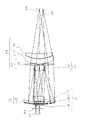
以下、図面を参照して、この発明の実施の形態について説明する。図1〜図12は、この発明の第1〜第12の実施の形態にかかる反射屈折光学系の構成を示す図である。各実施の形態にかかる反射屈折光学系PL1〜PL12は、軸外より最終像面(ウエハ面)に向かう光束の主光線b1〜b12が光軸に近づく方向に傾斜しており、また、最大物体高の物体面(マスク面)より入射する光束の主光線a1〜a12の傾斜角θ1が、
−10゜<θ1<2゜
の条件を満足する。ただし、この場合に物体面から発せられた光線が光軸から離れる方向の傾斜角度を+とする。Embodiments of the present invention will be described below with reference to the drawings. FIGS. 1-12 is a figure which shows the structure of the catadioptric optical system concerning the 1st-12th embodiment of this invention. The catadioptric optical systems PL1 to PL12 according to the respective embodiments are inclined such that the principal rays b1 to b12 of the light beam traveling from the off-axis toward the final image plane (wafer surface) approach the optical axis, and the maximum object The inclination angle θ1 of principal rays a1 to a12 of a light beam incident from a high object surface (mask surface) is
The condition of −10 ° <θ1 <2 ° is satisfied. However, in this case, the inclination angle in the direction in which the light beam emitted from the object plane is away from the optical axis is defined as +.
各実施の形態にかかる反射屈折光学系PL1〜PL12は、物体面(即ちマスクM1〜M12側)より光の進行方向に沿って、所望の屈折力を有する第1の屈折レンズ群G1と、発散作用を有する第1の反射レンズ群G2と、集光作用を有し、中心部に開口を有する第2の反射レンズ群G3と、3枚以上のレンズで構成され、最も前記第2の反射レンズ群側に第1集光レンズ群G5を有し、光の進行方向に沿って正負正の屈折力を有する第2屈折レンズ群G4を備え、以下に示す(1)〜(4)の条件を満足する。 The catadioptric optical systems PL1 to PL12 according to each embodiment include a first refractive lens group G1 having a desired refractive power and a divergence along the light traveling direction from the object plane (that is, the mask M1 to M12 side). The first reflecting lens group G2 having an action, the second reflecting lens group G3 having a condensing action and having an opening at the center, and three or more lenses, the second reflecting lens being the most. It has a first condenser lens group G5 on the group side, a second refractive lens group G4 having positive and negative refractive power along the light traveling direction, and the following conditions (1) to (4) are satisfied: Satisfied.
(1)−0.9 < φ1/φr2 < 1.7
(2)−1.5 < φr1/φr2 < −0.5
(3) 0.1 < φ2/φr2 < 0.7
(4) 0.3 < φ2a/φ2 < 1.4
但し、
φ1 :第1の屈折レンズ群の屈折力
φr1:第1の反射レンズ群の屈折力
φr2:第2の反射レンズ群の屈折力
φ2 :第2の屈折レンズ群の屈折力
φ2a:第2屈折レンズ群中の第1集光レンズ群の屈折力
図1に示す第1の実施の形態において、第1の屈折レンズ群G1は、物体面(マスクM1側)から像面W1に向けて光線の進行方向に沿って、物体側に凹面を向けた正メニスカスレンズL11、物体側に凹面を向けた負メニスカスレンズL12、物体側に凹面を向けた正メニスカスレンズL13により構成されている。第1の反射レンズ群G2は、物体側に凸面を向けた負メニスカスレンズL14により構成されている。なお、負メニスカスレンズL14は、裏面反射鏡として用いられる。第2の反射レンズ群G3は、物体側に凸面を向けた負メニスカスレンズL15により構成されている。なお、負メニスカスレンズL15は、裏面反射鏡として用いられる。(1) -0.9 <φ1 / φr2 <1.7
(2) -1.5 <φr1 / φr2 <−0.5
(3) 0.1 <φ2 / φr2 <0.7
(4) 0.3 <φ2a / φ2 <1.4
However,
φ1: refractive power of the first refractive lens group φr1: refractive power of the first reflective lens group φr2: refractive power of the second reflective lens group φ2: refractive power of the second refractive lens group φ2a: second refractive lens Refracting power of the first condenser lens group in the group In the first embodiment shown in FIG. 1, the first refractive lens group G1 travels light rays from the object plane (mask M1 side) toward the image plane W1. A positive meniscus lens L11 having a concave surface facing the object side, a negative meniscus lens L12 having a concave surface facing the object side, and a positive meniscus lens L13 having a concave surface facing the object side along the direction. The first reflecting lens group G2 includes a negative meniscus lens L14 having a convex surface directed toward the object side. The negative meniscus lens L14 is used as a back reflector. The second reflecting lens group G3 includes a negative meniscus lens L15 having a convex surface directed toward the object side. The negative meniscus lens L15 is used as a back reflector.
第2屈折レンズ群G4は、物体側に凸面を向けた正メニスカスレンズL16、物体側に凸面を向けた負メニスカスレンズL17、物体側に凸面を向けた正メニスカスレンズL18により構成される。なお、物体側に凸面を向けた正メニスカスレンズL16は、第1集光レンズ群G5を構成し、第2屈折レンズ群G4は、レンズL16,L17,L18で正負正の屈折力配置(パワー配置)を有する。 The second refractive lens group G4 includes a positive meniscus lens L16 having a convex surface facing the object side, a negative meniscus lens L17 having a convex surface facing the object side, and a positive meniscus lens L18 having a convex surface facing the object side. The positive meniscus lens L16 having a convex surface directed toward the object side constitutes the first condenser lens group G5, and the second refractive lens group G4 has positive and negative refractive power arrangement (power arrangement) by the lenses L16, L17, and L18. ).
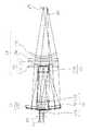
図2に示す第2の実施の形態において、第1の屈折レンズ群G1は、物体面(マスクM2側)から像面W2に向けて光線の進行方向に沿って、物体側に凹面を向けた正メニスカスレンズL21、物体側に凹面を向けた負メニスカスレンズL22、物体側に凹面を向けた正メニスカスレンズL23により構成されている。第1の反射レンズ群G2は、両凹レンズL24により構成されている。なお、両凹レンズL24は、裏面反射鏡として用いられる。第2の反射レンズ群G3は、物体側に凸面を向けた負メニスカスレンズL25により構成されている。なお、負メニスカスレンズL25は、裏面反射鏡として用いられる。 In the second embodiment shown in FIG. 2, the first refractive lens group G1 has a concave surface directed toward the object side along the traveling direction of light rays from the object plane (mask M2 side) toward the image plane W2. The lens includes a positive meniscus lens L21, a negative meniscus lens L22 having a concave surface facing the object side, and a positive meniscus lens L23 having a concave surface facing the object side. The first reflecting lens group G2 is composed of a biconcave lens L24. The biconcave lens L24 is used as a back reflector. The second reflecting lens group G3 includes a negative meniscus lens L25 having a convex surface directed toward the object side. The negative meniscus lens L25 is used as a back reflecting mirror.
第2屈折レンズ群G4は、物体側に凹面を向けた正メニスカスレンズL26、物体側に凸面を向けた正メニスカスレンズL27、物体側に凸面を向けた負メニスカスレンズL28、物体側に凸面を向けた正メニスカスレンズL29により構成される。なお、正メニスカスレンズL26及び正メニスカスレンズL27は、第1集光レンズ群G5を構成する。または、第2屈折レンズ群G4は、レンズL26とL27で正、レンズL28で負、レンズL29で正のパワー配置を有する。 The second refractive lens group G4 includes a positive meniscus lens L26 having a concave surface facing the object side, a positive meniscus lens L27 having a convex surface facing the object side, a negative meniscus lens L28 having a convex surface facing the object side, and a convex surface facing the object side. And a positive meniscus lens L29. The positive meniscus lens L26 and the positive meniscus lens L27 form a first condenser lens group G5. Alternatively, the second refractive lens group G4 has a positive power arrangement with the lenses L26 and L27, a negative with the lens L28, and a positive power with the lens L29.
図3に示す第3の実施の形態において、第1の屈折レンズ群G1は、物体面(マスクM3側)から像面W3に向けて光線の進行方向に沿って、物体側に凹面を向けた正メニスカスレンズL31、物体側に凹面を向けた負メニスカスレンズL32、物体側に凹面を向けた正メニスカスレンズL33により構成されている。第1の反射レンズ群G2は、両凹レンズL34により構成されている。なお、両凹レンズL34は、裏面反射鏡として用いられる。第2の反射レンズ群G3は、物体側に凸面を向けた負メニスカスレンズL35により構成されている。なお、負メニスカスレンズL35は、裏面反射鏡として用いられる。 In the third embodiment shown in FIG. 3, the first refractive lens group G1 has a concave surface directed toward the object side along the traveling direction of light rays from the object plane (mask M3 side) toward the image plane W3. The lens includes a positive meniscus lens L31, a negative meniscus lens L32 having a concave surface facing the object side, and a positive meniscus lens L33 having a concave surface facing the object side. The first reflecting lens group G2 is composed of a biconcave lens L34. The biconcave lens L34 is used as a back reflector. The second reflecting lens group G3 includes a negative meniscus lens L35 having a convex surface directed toward the object side. The negative meniscus lens L35 is used as a back reflector.
第2屈折レンズ群G4は、物体側に凹面を向けた正メニスカスレンズL36、物体側に凸面を向けた正メニスカスレンズL37、両凹レンズL38、物体側に凸面を向けた負メニスカスレンズL39、物体側に凸面を向けた正メニスカスレンズL40により構成される。なお、正メニスカスレンズL36及び正メニスカスレンズL37は、第1集光レンズ群G5を構成し、第2屈折レンズ群G4は、レンズL36とL37で正、レンズL38とL39で負、レンズL40で正のパワー配置を有する。 The second refractive lens group G4 includes a positive meniscus lens L36 having a concave surface facing the object side, a positive meniscus lens L37 having a convex surface facing the object side, a biconcave lens L38, a negative meniscus lens L39 having a convex surface facing the object side, an object side And a positive meniscus lens L40 having a convex surface facing the surface. The positive meniscus lens L36 and the positive meniscus lens L37 constitute a first condenser lens group G5, and the second refractive lens group G4 is positive with the lenses L36 and L37, negative with the lenses L38 and L39, and positive with the lens L40. Power arrangement.
図4に示す第4の実施の形態において、第1の屈折レンズ群G1は、物体面(マスクM4側)から像面W4に向けて光線の進行方向に沿って、物体側に凹面を向けた正メニスカスレンズL41、物体側に凹面を向けた負メニスカスレンズL42、物体側に凹面を向けた正メニスカスレンズL43により構成されている。第1の反射レンズ群G2は、物体側に凸面を向けた負メニスカスレンズL44により構成されている。なお、負メニスカスレンズL44は、裏面反射鏡として用いられる。第2の反射レンズ群G3は、物体側に凸面を向けた負メニスカスレンズL45により構成されている。なお、負メニスカスレンズL45は、裏面反射鏡として用いられる。 In the fourth embodiment shown in FIG. 4, the first refractive lens group G1 has a concave surface directed toward the object side along the traveling direction of the light beam from the object plane (mask M4 side) toward the image plane W4. The lens includes a positive meniscus lens L41, a negative meniscus lens L42 having a concave surface facing the object side, and a positive meniscus lens L43 having a concave surface facing the object side. The first reflecting lens group G2 includes a negative meniscus lens L44 having a convex surface directed toward the object side. The negative meniscus lens L44 is used as a back reflector. The second reflecting lens group G3 includes a negative meniscus lens L45 having a convex surface directed toward the object side. The negative meniscus lens L45 is used as a back reflector.
第2屈折レンズ群G4は、両凸レンズL46、物体側に凸面を向けた負メニスカスレンズL47、物体側に凸面を向けた正メニスカスレンズL48により構成される。なお、両凸レンズL46は、第1集光レンズ群G5を構成する。 The second refractive lens group G4 includes a biconvex lens L46, a negative meniscus lens L47 having a convex surface facing the object side, and a positive meniscus lens L48 having a convex surface facing the object side. The biconvex lens L46 constitutes the first condenser lens group G5.
図5に示す第5の実施の形態において、第1の屈折レンズ群G1は、物体面(マスクM5側)から像面W5に向けて光線の進行方向に沿って、物体側に凹面を向けた正メニスカスレンズL51、物体側に凹面を向けた負メニスカスレンズL52、物体側に凹面を向けた正メニスカスレンズL53により構成されている。第1の反射レンズ群G2は、両凹レンズL54により構成されている。なお、両凹レンズL54は、裏面反射鏡として用いられる。第2の反射レンズ群G3は、物体側に凸面を向けた負メニスカスレンズL55により構成されている。なお、負メニスカスレンズL55は、裏面反射鏡として用いられる。 In the fifth embodiment shown in FIG. 5, the first refractive lens group G1 has a concave surface directed toward the object side along the traveling direction of light rays from the object plane (mask M5 side) toward the image plane W5. A positive meniscus lens L51, a negative meniscus lens L52 having a concave surface facing the object side, and a positive meniscus lens L53 having a concave surface facing the object side. The first reflecting lens group G2 is composed of a biconcave lens L54. The biconcave lens L54 is used as a back reflector. The second reflecting lens group G3 includes a negative meniscus lens L55 having a convex surface directed toward the object side. The negative meniscus lens L55 is used as a back reflector.
第2屈折レンズ群G4は、物体側に凹面を向けた正メニスカスレンズL56、物体側に凸面を向けた正メニスカスレンズL57、物体側に凹面を向けた負メニスカスレンズL58、物体側に凸面を向けた正メニスカスレンズL59により構成される。なお、正メニスカスレンズL56及び正メニスカスレンズL57は、第1集光レンズ群G5を構成する。また、第2屈折レンズ群G4は、レンズL56とL57で正、レンズL58で負、レンズL59で正のパワー配置を有する。 The second refractive lens group G4 includes a positive meniscus lens L56 having a concave surface facing the object side, a positive meniscus lens L57 having a convex surface facing the object side, a negative meniscus lens L58 having a concave surface facing the object side, and a convex surface facing the object side. And a positive meniscus lens L59. The positive meniscus lens L56 and the positive meniscus lens L57 constitute a first condenser lens group G5. The second refractive lens group G4 has a positive power arrangement with the lenses L56 and L57, a negative with the lens L58, and a positive power with the lens L59.
図6に示す第6の実施の形態において、第1の屈折レンズ群G1は、物体面(マスクM6側)から像面W6に向けて光線の進行方向に沿って、物体側に凹面を向けた正メニスカスレンズL61、物体側に凹面を向けた負メニスカスレンズL62、物体側に凹面を向けた正メニスカスレンズL63により構成されている。第1の反射レンズ群G2は、両凹レンズL64により構成されている。なお、両凹レンズL64は、裏面反射鏡として用いられる。第2の反射レンズ群G3は、物体側に凸面を向けた負メニスカスレンズL65により構成されている。なお、負メニスカスレンズL65は、裏面反射鏡として用いられる。 In the sixth embodiment shown in FIG. 6, the first refractive lens group G1 has a concave surface directed toward the object side along the traveling direction of light rays from the object plane (mask M6 side) toward the image plane W6. The lens includes a positive meniscus lens L61, a negative meniscus lens L62 having a concave surface facing the object side, and a positive meniscus lens L63 having a concave surface facing the object side. The first reflecting lens group G2 is composed of a biconcave lens L64. The biconcave lens L64 is used as a back reflector. The second reflecting lens group G3 includes a negative meniscus lens L65 having a convex surface directed toward the object side. The negative meniscus lens L65 is used as a back reflector.
第2屈折レンズ群G4は、物体側に凹面を向けた正メニスカスレンズL66、物体側に凸面を向けた正メニスカスレンズL67、物体側に凹面を向けた負メニスカスレンズL68、物体側に凸面を向けた正メニスカスレンズL69、物体側に凸面を向けた負メニスカスレンズL70により構成される。なお、正メニスカスレンズL66、L67は、第1集光レンズ群G5を構成する。第2屈折レンズ群G4は、レンズL66とL67で正、レンズL68で負、レンズL69とL70で正のパワー配置を有する。 The second refractive lens group G4 includes a positive meniscus lens L66 having a concave surface facing the object side, a positive meniscus lens L67 having a convex surface facing the object side, a negative meniscus lens L68 having a concave surface facing the object side, and a convex surface facing the object side. The positive meniscus lens L69 and the negative meniscus lens L70 having a convex surface facing the object side. The positive meniscus lenses L66 and L67 constitute the first condenser lens group G5. The second refractive lens group G4 has a positive power arrangement with the lenses L66 and L67, a negative lens L68, and a positive power arrangement with the lenses L69 and L70.
図7に示す第7の実施の形態において、第1の屈折レンズ群G1は、物体面(マスクM7側)から像面W7に向けて光線の進行方向に沿って、物体側に凹面を向けた正メニスカスレンズL71、物体側に凹面を向けた負メニスカスレンズL72、物体側に凹面を向けた正メニスカスレンズL73により構成されている。第1の反射レンズ群G2は、物体側に凸面を向けた正メニスカスレンズL74、物体側に凸面である反射面を向けた反射鏡R71により構成されている。第2の反射レンズ群G3は、物体側に凸面を向けた負メニスカスレンズL75、像側に凹面である反射面を向けた反射鏡R72により構成されている。 In the seventh embodiment shown in FIG. 7, the first refractive lens group G1 has a concave surface directed toward the object side along the traveling direction of light rays from the object plane (mask M7 side) toward the image plane W7. A positive meniscus lens L71, a negative meniscus lens L72 having a concave surface facing the object side, and a positive meniscus lens L73 having a concave surface facing the object side. The first reflecting lens group G2 includes a positive meniscus lens L74 having a convex surface facing the object side, and a reflecting mirror R71 having a reflecting surface that is a convex surface facing the object side. The second reflecting lens group G3 includes a negative meniscus lens L75 having a convex surface facing the object side, and a reflecting mirror R72 having a concave reflecting surface facing the image side.
第2屈折レンズ群G4は、物体側に凸面を向けた正メニスカスレンズL76、両凹レンズL77、物体側に凸面を向けた正メニスカスレンズL78により構成される。なお、正メニスカスレンズL76は、第1集光レンズ群G5を構成する。 The second refractive lens group G4 includes a positive meniscus lens L76 having a convex surface facing the object side, a biconcave lens L77, and a positive meniscus lens L78 having a convex surface facing the object side. The positive meniscus lens L76 constitutes the first condenser lens group G5.
図8に示す第8の実施の形態において、第1の屈折レンズ群G1は、物体面(マスクM8側)から像面W8に向けて光線の進行方向に沿って、物体側に凹面を向けた負メニスカスレンズL81、物体側に凹面を向けた正メニスカスレンズL82、物体側に凹面を向けた正メニスカスレンズL83により構成されている。第1の反射レンズ群G2は、物体側に凸面を向けた負メニスカスレンズL84により構成されている。なお、負メニスカスレンズL84は、裏面反射鏡として用いられる。第2の反射レンズ群G3は、物体側に凸面を向けた負メニスカスレンズL85により構成されている。なお、負メニスカスレンズL85は、裏面反射鏡として用いられる。 In the eighth embodiment shown in FIG. 8, the first refractive lens group G1 has a concave surface directed toward the object side along the traveling direction of light rays from the object plane (mask M8 side) toward the image plane W8. A negative meniscus lens L81, a positive meniscus lens L82 having a concave surface facing the object side, and a positive meniscus lens L83 having a concave surface facing the object side. The first reflecting lens group G2 includes a negative meniscus lens L84 having a convex surface directed toward the object side. The negative meniscus lens L84 is used as a back reflecting mirror. The second reflecting lens group G3 includes a negative meniscus lens L85 having a convex surface directed toward the object side. The negative meniscus lens L85 is used as a back reflecting mirror.
第2屈折レンズ群G4は、両凸レンズL86、両凹レンズL87、物体側に凸面を向けた正メニスカスレンズL88により構成される。なお、両凸レンズL86は、第1集光レンズ群G5を構成する。 The second refractive lens group G4 includes a biconvex lens L86, a biconcave lens L87, and a positive meniscus lens L88 having a convex surface directed toward the object side. The biconvex lens L86 constitutes the first condenser lens group G5.
図9に示す第9の実施の形態において、第1の屈折レンズ群G1は、物体面(マスクM9側)から像面W9に向けて光線の進行方向に沿って、物体側に凹面を向けた負メニスカスレンズL91、物体側に凹面を向けた正メニスカスレンズL92、両凸レンズL93により構成されている。第1の反射レンズ群G2は、両凹レンズL94により構成されている。なお、両凹レンズL94は、裏面反射鏡として用いられる。第2の反射レンズ群G3は、物体側に凸面を向けた負メニスカスレンズL95により構成されている。なお、負メニスカスレンズL95は、裏面反射鏡として用いられる。 In the ninth embodiment shown in FIG. 9, the first refractive lens group G1 has a concave surface directed toward the object side along the traveling direction of the light beam from the object plane (mask M9 side) toward the image plane W9. The lens includes a negative meniscus lens L91, a positive meniscus lens L92 having a concave surface facing the object side, and a biconvex lens L93. The first reflecting lens group G2 includes a biconcave lens L94. The biconcave lens L94 is used as a back reflector. The second reflecting lens group G3 includes a negative meniscus lens L95 having a convex surface directed toward the object side. The negative meniscus lens L95 is used as a back reflector.
第2屈折レンズ群G4は、両凸レンズL96、両凹レンズL97、物体側に凸面を向けた正メニスカスレンズL98により構成される。なお、両凸レンズL96は、第1集光レンズ群G5を構成する。 The second refractive lens group G4 includes a biconvex lens L96, a biconcave lens L97, and a positive meniscus lens L98 having a convex surface directed toward the object side. The biconvex lens L96 constitutes the first condenser lens group G5.
図10に示す第10の実施の形態において、第1の屈折レンズ群G1は、物体面(マスクM10側)から像面W10に向けて光線の進行方向に沿って、物体側に凹面を向けた正メニスカスレンズL101、両凹レンズL102、両凸レンズL103により構成されている。第1の反射レンズ群G2は、物体側に凸面を向けた負メニスカスレンズL104により構成されている。なお、負メニスカスレンズL104は、裏面反射鏡として用いられる。第2の反射レンズ群G3は、物体側に凸面を向けた負メニスカスレンズL105により構成されている。なお、負メニスカスレンズL105は、裏面反射鏡として用いられる。 In the tenth embodiment shown in FIG. 10, the first refractive lens group G1 has a concave surface directed toward the object side along the traveling direction of light rays from the object plane (mask M10 side) toward the image plane W10. The lens includes a positive meniscus lens L101, a biconcave lens L102, and a biconvex lens L103. The first reflecting lens group G2 includes a negative meniscus lens L104 having a convex surface directed toward the object side. The negative meniscus lens L104 is used as a back reflector. The second reflecting lens group G3 includes a negative meniscus lens L105 having a convex surface directed toward the object side. The negative meniscus lens L105 is used as a back surface reflecting mirror.
第2屈折レンズ群G4は、両凸レンズL106、両凹レンズL107、物体側に凸面を向けた正メニスカスレンズL108により構成される。なお、両凸レンズL106は、第1集光レンズ群G5を構成し、第2屈折レンズ群G4は、レンズL106,L107,L108で正負正のパワー配置を有する。 The second refractive lens group G4 includes a biconvex lens L106, a biconcave lens L107, and a positive meniscus lens L108 having a convex surface facing the object side. The biconvex lens L106 constitutes a first condenser lens group G5, and the second refractive lens group G4 has a positive and negative power arrangement with the lenses L106, L107, and L108.
図11に示す第11の実施の形態において、第1の屈折レンズ群G1は、物体面(マスクM11側)から像面W11に向けて光線の進行方向に沿って、両凹レンズL111、物体側に凹面を向けた負メニスカスレンズL112、物体側に凹面を向けた正メニスカスレンズL113により構成されている。第1の反射レンズ群G2は、物体側に凸面を向けた正メニスカスレンズL114、物体側に凸面である反射面を向けた反射鏡R111により構成されている。第2の反射レンズ群G3は、物体側に凸面を向けた負メニスカスレンズL115、像側に凹面である反射面を向けた反射鏡R112により構成されている。 In the eleventh embodiment shown in FIG. 11, the first refractive lens group G1 has a biconcave lens L111 on the object side along the traveling direction of light rays from the object plane (mask M11 side) toward the image plane W11. It is composed of a negative meniscus lens L112 having a concave surface and a positive meniscus lens L113 having a concave surface on the object side. The first reflecting lens group G2 includes a positive meniscus lens L114 having a convex surface facing the object side, and a reflecting mirror R111 having a reflecting surface that is a convex surface facing the object side. The second reflecting lens group G3 includes a negative meniscus lens L115 having a convex surface facing the object side and a reflecting mirror R112 having a concave reflecting surface facing the image side.
第2屈折レンズ群G4は、物体側に凸面を向けた正メニスカスレンズL116、両凹レンズL117、物体側に凸面を向けた正メニスカスレンズL118により構成される。なお、正メニスカスレンズL116は、第1集光レンズ群G5を構成する。 The second refractive lens group G4 includes a positive meniscus lens L116 having a convex surface facing the object side, a biconcave lens L117, and a positive meniscus lens L118 having a convex surface facing the object side. The positive meniscus lens L116 constitutes the first condenser lens group G5.
図12に示す第12の実施の形態において、第1の屈折レンズ群G1は、物体面(マスクM12側)から像面W12に向けて光線の進行方向に沿って、両凹レンズL121、物体側に凹面を向けた負メニスカスレンズL122、物体側に凹面を向けた正メニスカスレンズL123により構成されている。第1の反射レンズ群G2は、物体側に凸面を向けた正メニスカスレンズL124、物体側に凸面である反射面を向けた反射鏡R121により構成されている。第2の反射レンズ群G3は、物体側に凸面を向けた負メニスカスレンズL125、像側に凹面である反射面を向けた反射鏡R122により構成されている。 In the twelfth embodiment shown in FIG. 12, the first refractive lens group G1 has a biconcave lens L121 on the object side along the traveling direction of light rays from the object plane (mask M12 side) toward the image plane W12. The lens includes a negative meniscus lens L122 having a concave surface and a positive meniscus lens L123 having a concave surface facing the object. The first reflecting lens group G2 includes a positive meniscus lens L124 having a convex surface facing the object side, and a reflecting mirror R121 having a reflecting surface that is a convex surface facing the object side. The second reflecting lens group G3 includes a negative meniscus lens L125 having a convex surface facing the object side and a reflecting mirror R122 having a concave reflecting surface facing the image side.
第2屈折レンズ群G4は、物体側に凸面を向けた正メニスカスレンズL126、物体側に凸面を向けた負メニスカスレンズL127、物体側に凸面を向けた正メニスカスレンズL128により構成される。なお、正メニスカスレンズL126は、第1集光レンズ群G5を構成する。 The second refractive lens group G4 includes a positive meniscus lens L126 having a convex surface facing the object side, a negative meniscus lens L127 having a convex surface facing the object side, and a positive meniscus lens L128 having a convex surface facing the object side. The positive meniscus lens L126 constitutes the first condenser lens group G5.
上述の第1〜第12の反射屈折光学系PL1〜PL12によれば、上記(1)の条件式を満たすため、物体からの光束の発散を小さくし第1の反射レンズ群を小さくでき、また光束の中心部分の不使用領域を小さくでき、良好な結像性能を得ることができる。また光量の低下も抑制することができる。また、上記(1)の条件式を満たすため、第1の屈折レンズ群と第1の反射レンズ群とを充分に離したレイアウトを実現することができ、光束のけられ量を小さくすることができ、光量の低下を抑制し良好な結像性能を得ることができる。 According to the above-described first to twelfth catadioptric optical systems PL1 to PL12, since the conditional expression (1) is satisfied, the divergence of the light beam from the object can be reduced, and the first reflecting lens group can be reduced. The unused area at the center of the light beam can be reduced, and good imaging performance can be obtained. In addition, a decrease in the amount of light can be suppressed. In addition, since the conditional expression (1) is satisfied, a layout in which the first refractive lens group and the first reflective lens group are sufficiently separated can be realized, and the amount of luminous flux can be reduced. It is possible to suppress the decrease of the light amount and obtain good imaging performance.
また、上記(2)の条件式を満たしているため、ペッツバール和を0近傍にすることが容易になり像面湾曲の補正を容易に行うことができる。更に、上記(3)の条件式を満たしているため、第2屈折レンズ群のパワーの増大を抑制し、色収差の発生を小さく抑えることができる。また、第2の反射レンズ群にて集光される集光角を小さくでき、第1の反射レンズ群でけられる光束を小さくでき、光量の低下を抑制し良好な結像性能を得ることができる。 Further, since the conditional expression (2) is satisfied, it is easy to make the Petzval sum close to 0 and the field curvature can be easily corrected. Furthermore, since the conditional expression (3) is satisfied, an increase in the power of the second refractive lens group can be suppressed, and the occurrence of chromatic aberration can be suppressed to a low level. In addition, it is possible to reduce the condensing angle collected by the second reflecting lens group, to reduce the luminous flux produced by the first reflecting lens group, and to obtain a good imaging performance by suppressing a decrease in the amount of light. it can.
また、上記(4)の条件式を満たしているため、第2の屈折レンズ群を構成する、正負正のレンズ群のうちの像面に近い側の正の群が強くなりすぎるのを防止でき、コマ収差の発生量を小さく抑えることができ補正を容易に行うことができる。また上記(4)の条件式を満たすため、第2の屈折レンズ群を構成する、正負正のレンズ群のうちの物体面に近い側の正の群が強くなりすぎるのを防止でき、コマ収差の発生量を小さく抑えることができ、補正を容易に行うことができる。 Further, since the conditional expression (4) is satisfied, it is possible to prevent the positive group close to the image plane in the positive and negative lens groups constituting the second refractive lens group from becoming too strong. Thus, the amount of coma generated can be reduced and correction can be performed easily. In addition, since the conditional expression (4) is satisfied, it is possible to prevent the positive group close to the object plane in the positive and negative lens groups constituting the second refractive lens group from becoming too strong, and coma aberration. Generation amount can be suppressed small, and correction can be easily performed.
また、最大物体高の物体面より入射する光束の主光線a1〜a12の傾斜角θ1が、
−10゜<θ1<2゜
の条件を満足しているため、第1反射レンズ群G2の反射面を小さくすることができる。Further, the inclination angle θ1 of the principal rays a1 to a12 of the light beam incident from the object surface having the maximum object height is
Since the condition of −10 ° <θ1 <2 ° is satisfied, the reflecting surface of the first reflecting lens group G2 can be made small.
次に、図13を参照して、第13の実施の形態としての、上述の第1〜第12の実施の形態にかかる反射屈折光学系PL1〜PL12を備えた投影露光装置について説明する。図13は、この発明の第13の実施の形態にかかるステップアンドリピート方式の投影露光装置の概略構成を示す図である。また、以下の説明においては、図13中に示すXYZ直交座標系を設定し、このXYZ直交座標系を参照しつつ各部材の位置関係について説明する。XYZ直交座標系は、X軸及びY軸がウエハWに対して平行となるよう設定され、Z軸がウエハWに対して直交する方向に設定されている。図中のXYZ座標系は、実際にはXY平面が水平面に平行な面に設定され、Z軸が鉛直上方向に設定される。 Next, a projection exposure apparatus including the catadioptric optical systems PL1 to PL12 according to the first to twelfth embodiments as a thirteenth embodiment will be described with reference to FIG. FIG. 13 is a view showing the schematic arrangement of a step-and-repeat projection exposure apparatus according to the thirteenth embodiment of the present invention. In the following description, the XYZ orthogonal coordinate system shown in FIG. 13 is set, and the positional relationship of each member will be described with reference to this XYZ orthogonal coordinate system. The XYZ orthogonal coordinate system is set so that the X axis and the Y axis are parallel to the wafer W, and the Z axis is set in a direction orthogonal to the wafer W. In the XYZ coordinate system in the figure, the XY plane is actually set to a plane parallel to the horizontal plane, and the Z-axis is set vertically upward.
この第13の実施の形態にかかる投影露光装置は、図13に示すように、光源を含み、オプティカル・インテグレータ、視野絞り、コンデンサレンズ等から構成される照明光学系ILを備えている。光源から射出された露光光は、照明光学系ILを通過し、マスクMに設けられたパターンを照明する。マスクMを通過した光は、第1〜第12の実施の形態にかかる反射屈折光学系PL1〜PL12の何れかを介して、外径が500mmより大きいフラットパネルディスプレイ用のプレート(またはウエはW)P上の露光領域に投影露光する。ここで、外径が500mmよりも大きいとは、一辺若しくは対角線が500mmよりも大きいことをいう。 As shown in FIG. 13, the projection exposure apparatus according to the thirteenth embodiment includes an illumination optical system IL including a light source and including an optical integrator, a field stop, a condenser lens, and the like. The exposure light emitted from the light source passes through the illumination optical system IL and illuminates the pattern provided on the mask M. The light that has passed through the mask M passes through any one of the catadioptric optical systems PL1 to PL12 according to the first to twelfth embodiments, and the plate for a flat panel display having an outer diameter larger than 500 mm (or the wafer is W ) Projection exposure is performed on an exposure area on P. Here, that the outer diameter is larger than 500 mm means that one side or diagonal line is larger than 500 mm.
また、マスクMはマスクステージMST上に保持されている。マスクステージMSTは、X方向、Y方向に微動可能、及びZ方向を軸として微小に回転可能に構成されている。マスクステージMSTは、マスクレーザ干渉計(図示せず)によってX方向、Y方向及び回転方向の位置をリアルタイムに計測され、且つ制御されている。 The mask M is held on the mask stage MST. The mask stage MST is configured to be finely movable in the X direction and the Y direction, and to be slightly rotatable around the Z direction. In the mask stage MST, the positions in the X direction, the Y direction, and the rotation direction are measured and controlled in real time by a mask laser interferometer (not shown).
また、プレートPはプレートステージPST上に保持されている。プレートステージPSTは、X方向、Y方向に移動可能、及びZ方向を軸として回転可能に構成されている。プレートステージPSTは、ウエハレーザ干渉計(図示せず)によってX方向、Y方向及び回転方向の位置をリアルタイムに計測され、且つ制御されている。 The plate P is held on the plate stage PST. The plate stage PST is configured to be movable in the X direction and the Y direction, and to be rotatable about the Z direction. In the plate stage PST, the positions in the X direction, the Y direction, and the rotation direction are measured and controlled in real time by a wafer laser interferometer (not shown).
この投影露光装置に備えられている制御部6は、マスクレーザ干渉計により計測された計測値に基づいてマスクMのX方向、Y方向及び回転方向の位置の調整を行なう。即ち、制御部6は、マスクステージ駆動部8に制御信号を送信し、マスクステージMSTを微動させることによりマスクMの位置調整を行なう。 The
また、制御部6は、プレートレーザ干渉計により計測された計測値に基づいてプレートPのX方向、Y方向及び回転方向の位置の調整を行なう。即ち、制御部6は、基板ステージ駆動部10に制御信号を送信し、基板ステージ駆動部10によりプレートステージPSTを駆動させることによりプレートPのX方向、Y方向及び回転方向の位置調整を行なう。 Further, the
露光時には、制御部6は、基板ステージ駆動部10に制御信号を出力し、プレートPを載置するプレートステージPSTを駆動させることによりプレートP上の各ショット領域を順次露光位置にステップ移動させる。即ち、ステップアンドリピート方式によりマスクMのパターン像をプレートP上に露光する動作を繰り返す。 At the time of exposure, the
この第13の実施の形態にかかる投影露光装置によれば、広い露光領域、高い解像力及び良好な光学特性を有する反射屈折光学系を備えているため、プレート上に微細なパターンを高スループットで露光することができる。 The projection exposure apparatus according to the thirteenth embodiment includes a catadioptric optical system having a wide exposure area, high resolution, and good optical characteristics, so that fine patterns can be exposed on a plate with high throughput. can do.
なお、第13の実施の形態はマスクMのパターン像をプレートP上に一括露光する露光装置であったが、これに限られることなく、反射屈折光学系PL1〜PL12に対してプレートPを走査方向に移動させつつ露光を行う走査型露光装置(ステップアンドスキャン方式の露光装置)としても良い。 Although the thirteenth embodiment is an exposure apparatus that collectively exposes the pattern image of the mask M onto the plate P, the present invention is not limited to this, and the plate P is scanned with respect to the catadioptric optical systems PL1 to PL12. A scanning exposure apparatus (step-and-scan type exposure apparatus) that performs exposure while moving in the direction may be used.
なお、本発明による反射屈折型光学系PL1〜PL12は、装置の仕様あるいはレイアウトの都合により、前述の説明とは逆方向に光学系を通して使用してもよい。この場合、光学倍率βがβ=−1の光学系については倍率は変わらないが、それ以外のものについては拡大光学系は縮小光学系に、縮小光学系については拡大光学系となる。 Note that the catadioptric optical systems PL1 to PL12 according to the present invention may be used through the optical system in the direction opposite to the above description depending on the specifications of the apparatus or the layout. In this case, the magnification does not change for an optical system having an optical magnification β of β = −1, but for the other optical systems, the magnifying optical system becomes a reducing optical system, and the reducing optical system becomes a magnifying optical system.
上述の実施の形態にかかる投影露光装置では、照明光学系によってマスクMを照明し(照明工程)、この発明の第1〜第12の実施の形態にかかる反射屈折光学系PL1〜PL12を備える露光装置を用いて、マスクに形成された転写用のパターンを感光性基板(プレート)に露光する(露光工程)ことにより、マイクロデバイス(半導体素子、撮像素子、液晶表示素子、薄膜磁気ヘッド等)を製造することができる。以下、上述の実施の形態にかかる露光装置を用いて感光性基板としてのプレート等に所定の回路パターンを形成することによって、マイクロデバイスとしての半導体デバイスを得る際の手法の一例につき図14のフローチャートを参照して説明する。 In the projection exposure apparatus according to the above-described embodiment, the mask M is illuminated by the illumination optical system (illumination process), and exposure is provided with the catadioptric optical systems PL1 to PL12 according to the first to twelfth embodiments of the present invention. By exposing the pattern for transfer formed on the mask to the photosensitive substrate (plate) using an apparatus (exposure process), microdevices (semiconductor elements, imaging elements, liquid crystal display elements, thin film magnetic heads, etc.) can be obtained. Can be manufactured. FIG. 14 is a flowchart of an example of a method for obtaining a semiconductor device as a micro device by forming a predetermined circuit pattern on a plate or the like as a photosensitive substrate using the exposure apparatus according to the above-described embodiment. Will be described with reference to FIG.
先ず、図14のステップ301において、1ロットのプレート上に金属膜が蒸着される。次のステップ302において、その1ロットのプレート上の金属膜上にフォトレジストが塗布される。その後、ステップ303において、上述の実施の形態にかかる露光装置を用いて、マスク上のパターンの像がその投影光学系を介して、その1ロットのプレート上の各ショット領域に順次露光転写される。その後、ステップ304において、その1ロットのプレート上のフォトレジストの現像が行われた後、ステップ305において、その1ロットのプレート上でレジストパターンをマスクとしてエッチングを行うことによって、マスク上のパターンに対応する回路パターンが、各プレート上の各ショット領域に形成される。 First, in step 301 of FIG. 14, a metal film is deposited on one lot of plates. In the
その後、更に上のレイヤの回路パターンの形成等を行うことによって、半導体素子等のデバイスが製造される。上述の半導体デバイス製造方法によれば、高解像度を有し、かつ収差が良好に補正されている投影光学系を備えた露光装置を用いて露光を行なっているため、極めて微細な回路パターンを有する半導体デバイスを得ることができる。なお、ステップ301〜ステップ305では、プレート上に金属を蒸着し、その金属膜上にレジストを塗布、そして露光、現像、エッチングの各工程を行っているが、これらの工程に先立って、プレート上にシリコンの酸化膜を形成後、そのシリコンの酸化膜上にレジストを塗布、そして露光、現像、エッチング等の各工程を行っても良いことはいうまでもない。 Thereafter, a device pattern such as a semiconductor element is manufactured by forming a circuit pattern of an upper layer. According to the semiconductor device manufacturing method described above, since exposure is performed using an exposure apparatus having a projection optical system having high resolution and good aberration correction, it has an extremely fine circuit pattern. A semiconductor device can be obtained. In steps 301 to 305, a metal is vapor-deposited on the plate, a resist is applied on the metal film, and exposure, development, and etching processes are performed. Prior to these processes, the process is performed on the plate. It is needless to say that after forming a silicon oxide film, a resist may be applied on the silicon oxide film, and steps such as exposure, development, and etching may be performed.
また、上述の実施の形態にかかる露光装置では、プレート(ガラス基板)上に所定のパターン(回路パターン、電極パターン等)を形成することによって、マイクロデバイスとしての液晶表示素子を得ることもできる。以下、図15のフローチャートを参照して、このときの手法の一例につき説明する。図15において、パターン形成工程401では、本実施形態の露光装置を用いてマスクのパターンを感光性基板(レジストが塗布されたガラス基板等)に転写露光する、所謂光リソグラフィ工程が実行される。この光リソグラフィ工程によって、感光性基板上には多数の電極等を含む所定パターンが形成される。その後、露光された基板は、現像工程、エッチング工程、レジスト剥離工程等の各工程を経ることによって、基板上に所定のパターンが形成され、次のカラーフィルタ形成工程402へ移行する。 In the exposure apparatus according to the above-described embodiment, a liquid crystal display element as a micro device can be obtained by forming a predetermined pattern (circuit pattern, electrode pattern, etc.) on a plate (glass substrate). Hereinafter, an example of the technique at this time will be described with reference to the flowchart of FIG. In FIG. 15, in a
次に、カラーフィルタ形成工程402では、R(Red)、G(Green)、B(Blue)に対応した3つのドットの組がマトリックス状に多数配列されたり、またはR、G、Bの3本のストライプのフィルタの組を複数水平走査線方向に配列されたりしたカラーフィルタを形成する。そして、カラーフィルタ形成工程402の後に、セル組み立て工程403が実行される。セル組み立て工程403では、パターン形成工程401にて得られた所定パターンを有する基板、およびカラーフィルタ形成工程402にて得られたカラーフィルタ等を用いて液晶パネル(液晶セル)を組み立てる。セル組み立て工程403では、例えば、パターン形成工程401にて得られた所定パターンを有する基板とカラーフィルタ形成工程402にて得られたカラーフィルタとの間に液晶を注入して、液晶パネル(液晶セル)を製造する。 Next, in the color filter forming step 402, a large number of sets of three dots corresponding to R (Red), G (Green), and B (Blue) are arranged in a matrix or three of R, G, and B A color filter is formed by arranging a plurality of stripe filter sets in the horizontal scanning line direction. Then, after the color filter forming step 402, a cell assembling step 403 is executed. In the cell assembling step 403, a liquid crystal panel (liquid crystal cell) is assembled using the substrate having the predetermined pattern obtained in the
その後、モジュール組み立て工程404にて、組み立てられた液晶パネル(液晶セル)の表示動作を行わせる電気回路、バックライト等の各部品を取り付けて液晶表示素子として完成させる。上述の液晶表示素子の製造方法によれば、高解像度を有し、かつ収差が良好に補正されている投影光学系を備えた露光装置を用いて露光しているため、極めて微細な回路パターンを有する液晶表示素子を得ることができる。 Thereafter, in a module assembling step 404, components such as an electric circuit and a backlight for performing a display operation of the assembled liquid crystal panel (liquid crystal cell) are attached to complete a liquid crystal display element. According to the above-described method for manufacturing a liquid crystal display element, since exposure is performed using an exposure apparatus having a projection optical system having high resolution and good aberration correction, an extremely fine circuit pattern is formed. The liquid crystal display element which has can be obtained.
以下に実施例1〜実施例12について説明するが、実施例1〜実施例12にかかる反射屈折光学系の構成は、図1〜図12に示す第1〜第12の実施の形態にかかる反射屈折光学系の構成とそれぞれ同一であるため、実施例1〜実施例12にかかる反射屈折光学系の説明には、第1〜第12の実施の形態にかかる反射屈折光学系の説明で用いた符号を用いる。また、実施例1〜実施例12にかかる反射屈折光学系PL1〜PL12の光学部材諸元を表1〜表12に示す。表1〜表12の光学部材諸元においては、第1カラムの面番号は物体側からの光線進行方向に沿った面の順序、第2カラムは各面の曲率半径(mm)、第3カラムの面間隔は光軸上の面間隔(mm)、第4カラムは光学部材の硝材の種類をそれぞれ示している。 Examples 1 to 12 will be described below, but the configurations of the catadioptric optical systems according to Examples 1 to 12 are the reflections according to the first to twelfth embodiments shown in FIGS. Since the configuration of the refractive optical system is the same, the description of the catadioptric optical system according to Examples 1 to 12 was used in the explanation of the catadioptric optical system according to the first to twelfth embodiments. A sign is used. In addition, Tables 1 to 12 show optical member specifications of the catadioptric optical systems PL1 to PL12 according to Examples 1 to 12. In the optical member specifications in Tables 1 to 12, the surface number of the first column is the order of the surfaces along the light beam traveling direction from the object side, the second column is the curvature radius (mm) of each surface, and the third column The distance between surfaces is the distance between surfaces on the optical axis (mm), and the fourth column indicates the type of glass material of the optical member.
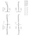
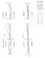
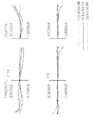
また、図16〜図27は第1〜第12実施例にかかる反射屈折光学系PL1〜PL12のタンジェンタル方向及びサジタル方向における収差図である。図16〜図27において、Yは物体高を示し、一点鎖線は波長365.0150nm、破線は波長404.6560nm、実線は波長435.8350nmにおける収差をそれぞれ示している。 FIGS. 16 to 27 are aberration diagrams of the catadioptric optical systems PL1 to PL12 according to the first to twelfth examples in the tangential direction and the sagittal direction. 16 to 27, Y indicates the object height, the alternate long and short dash line indicates the aberration at the wavelength of 365.0150 nm, the broken line indicates the aberration at the wavelength of 404.6560 nm, and the solid line indicates the aberration at the wavelength of 435.8350 nm.
実施例1にかかる反射屈折光学系PL1の諸元の値を示す。
(諸元)
物体側(マスク側)開口数(NA): 0.16
結像倍率: −1倍
条件式の対応値:
φ1/φr2=1.022
φr1/φr2=−0.801
φ2/φr2=0.281
φ2a/φ2=0.621
θ1=−3.49
(表1)
(光学部材諸元)
面番号 曲率半径 面間隔 硝材
OBJ: INFINITY 40.000000
1: -128.68355 21.966714 'SIO2'
2: -122.12281 11.906648
3: -94.81246 20.000000 'SIO2'
4: -144.01630 2.000000
5: -830.19014 32.681562 'SIO2'
6: -138.57267 277.050429
7: 1463.56525 60.000000 'SIO2'
STO: 1243.01126 -60.000000 REFL 'SIO2'
9: 1463.56525 -325.605353
10: 611.52098 -20.000000 'SIO2'
11: 825.10003 20.000000 REFL 'SIO2'
12: 611.52098 385.605353
13: 488.61920 60.000000 'SIO2'
14: 1203.81126 548.555628
15: 194.85133 60.000000 'SIO2'
16: 85.71301 2.000000
17: 83.10690 60.000000 'SIO2'
18: 168.88493 43.839019
IMG: INFINITY 0.000000
図16の収差図に示すように、この実施例に係る反射屈折光学系は、広い露光フィールド、及び広い波長帯域にわたってきわめて良好な収差補正を実現している。The value of the item of the catadioptric optical system PL1 concerning Example 1 is shown.
(Specifications)
Object side (mask side) numerical aperture (NA): 0.16
Imaging magnification: -1 times Corresponding value of conditional expression:
φ1 / φr2 = 1.022
φr1 / φr2 = −0.801
φ2 / φr2 = 0.281
φ2a / φ2 = 0.621
θ1 = −3.49
(Table 1)
(Optical member specifications)
Surface number Curvature radius Surface spacing Glass material
OBJ: INFINITY 40.000000
1: -128.68355 21.966714 'SIO2'
2: -122.12281 11.906648
3: -94.81246 20.000000 'SIO2'
4: -144.01630 2.000000
5: -830.19014 32.681562 'SIO2'
6: -138.57267 277.050429
7: 1463.56525 60.000000 'SIO2'
STO: 1243.01126 -60.000000 REFL 'SIO2'
9: 1463.56525 -325.605353
10: 611.52098 -20.000000 'SIO2'
11: 825.10003 20.000000 REFL 'SIO2'
12: 611.52098 385.605353
13: 488.61920 60.000000 'SIO2'
14: 1203.81126 548.555628
15: 194.85133 60.000000 'SIO2'
16: 85.71301 2.000000
17: 83.10690 60.000000 'SIO2'
18: 168.88493 43.839019
IMG: INFINITY 0.000000
As shown in the aberration diagram of FIG. 16, the catadioptric optical system according to this example realizes extremely good aberration correction over a wide exposure field and a wide wavelength band.
実施例2にかかる反射屈折光学系PL2の諸元の値を示す。
(諸元)
物体側(マスク側)開口数(NA): 0.16
結像倍率: −1倍
条件式の対応値:
φ1/φr2=1.677
φr1/φr2=−0.984
φ2/φr2=0.613
φ2a/φ2= 1.153
θ1=1.63
(表2)
(光学部材諸元)
面番号 曲率半径 面間隔 硝材
OBJ: INFINITY 40.000000
1: -244.47557 60.000000 'SIO2'
2: -135.32018 19.331452
3: -84.50694 20.000000 'SIO2'
4: -95.22919 2.000000
5: -492.74833 20.000000 'SIO2'
6: -174.34368 339.046163
7: -1395.29887 20.000000 'SIO2'
STO: 2325.15288 -20.000000 REFL 'SIO2'
9: -1395.29887 -360.377615
10: 615.17311 -60.000000 'SIO2'
11: 878.28164 60.000000 REFL 'SIO2'
12: 615.17311 400.377615
13: -20090.06594 23.541244 'SIO2'
14: -940.61600 2.000000
15: 439.29212 60.000000 'SIO2'
16: 1338.53273 15.287882
17: 9991.50867 60.000000 'SIO2'
18: 352.37670 132.365630
19: 256.95911 60.000000 'SIO2'
20: 606.24089 346.427629
IMG: INFINITY 0.000000
図17の収差図に示すように、この実施例に係る反射屈折光学系は、広い露光フィールド、及び広い波長帯域にわたってきわめて良好な収差補正を実現している。The value of the item of the catadioptric optical system PL2 concerning Example 2 is shown.
(Specifications)
Object side (mask side) numerical aperture (NA): 0.16
Imaging magnification: -1 times Corresponding value of conditional expression:
φ1 / φr2 = 1.777
φr1 / φr2 = −0.984
φ2 / φr2 = 0.613
φ2a / φ2 = 1.153
θ1 = 1.63
(Table 2)
(Optical member specifications)
Surface number Curvature radius Surface spacing Glass material
OBJ: INFINITY 40.000000
1: -244.47557 60.000000 'SIO2'
2: -135.32018 19.331452
3: -84.50694 20.000000 'SIO2'
4: -95.22919 2.000000
5: -492.74833 20.000000 'SIO2'
6: -174.34368 339.046163
7: -1395.29887 20.000000 'SIO2'
STO: 2325.15288 -20.000000 REFL 'SIO2'
9: -1395.29887 -360.377615
10: 615.17311 -60.000000 'SIO2'
11: 878.28164 60.000000 REFL 'SIO2'
12: 615.17311 400.377615
13: -20090.06594 23.541244 'SIO2'
14: -940.61600 2.000000
15: 439.29212 60.000000 'SIO2'
16: 1338.53273 15.287882
17: 9991.50867 60.000000 'SIO2'
18: 352.37670 132.365630
19: 256.95911 60.000000 'SIO2'
20: 606.24089 346.427629
IMG: INFINITY 0.000000
As shown in the aberration diagram of FIG. 17, the catadioptric optical system according to this example realizes very good aberration correction over a wide exposure field and a wide wavelength band.
実施例3にかかる反射屈折光学系PL3の諸元の値を示す。
(諸元)
物体側(マスク側)開口数(NA): 0.16
結像倍率: −1倍
条件式の対応値:
φ1/φr2=1.368
φr1/φr2=−0.918
φ2/φr2= 0.480
φ2a/φ2= 0.873
θ1=−0.87
(表3)
(光学部材諸元)
面番号 曲率半径 面間隔 硝材
OBJ: INFINITY 40.000000
1: -196.08960 50.804280 'SIO2'
2: -138.83997 16.777937
3: -88.01280 20.000000 'SIO2'
4: -108.82948 2.000000
5: -353.82910 20.482245 'SIO2'
6: -140.43347 301.773448
7: -2324.62408 60.000000 'SIO2'
STO: 2076.38768 -60.000000 REFL 'SIO2'
9: -2324.62408 -326.754637
10: 633.73300 -45.083273 'SIO2'
11: 871.89316 45.083273 REFL 'SIO2'
12: 633.73300 386.754637
13: -2520.75987 20.000000 'SIO2'
14: -868.48671 2.000000
15: 528.46406 26.663164 'SIO2'
16: 1637.20578 15.889081
17: -28763.25747 20.000000 'SIO2'
18: 1748.95577 344.910312
19: 948.77723 60.000000 'SIO2'
20: 230.21114 2.000000
21: 185.82488 29.528268 'SIO2'
22: 1122.29727 207.171313
IMG: INFINITY 0.000000
図18の収差図に示すように、この実施例に係る反射屈折光学系は、広い露光フィールド、及び広い波長帯域にわたってきわめて良好な収差補正を実現している。The value of the item of the catadioptric optical system PL3 concerning Example 3 is shown.
(Specifications)
Object side (mask side) numerical aperture (NA): 0.16
Imaging magnification: -1 times Corresponding value of conditional expression:
φ1 / φr2 = 1.368
φr1 / φr2 = −0.918
φ2 / φr2 = 0.480
φ2a / φ2 = 0.873
θ1 = −0.87
(Table 3)
(Optical member specifications)
Surface number Curvature radius Surface spacing Glass material
OBJ: INFINITY 40.000000
1: -196.08960 50.804280 'SIO2'
2: -138.83997 16.777937
3: -88.01280 20.000000 'SIO2'
4: -108.82948 2.000000
5: -353.82910 20.482245 'SIO2'
6: -140.43347 301.773448
7: -2324.62408 60.000000 'SIO2'
STO: 2076.38768 -60.000000 REFL 'SIO2'
9: -2324.62408 -326.754637
10: 633.73300 -45.083273 'SIO2'
11: 871.89316 45.083273 REFL 'SIO2'
12: 633.73300 386.754637
13: -2520.75987 20.000000 'SIO2'
14: -868.48671 2.000000
15: 528.46406 26.663164 'SIO2'
16: 1637.20578 15.889081
17: -28763.25747 20.000000 'SIO2'
18: 1748.95577 344.910312
19: 948.77723 60.000000 'SIO2'
20: 230.21114 2.000000
21: 185.82488 29.528268 'SIO2'
22: 1122.29727 207.171313
IMG: INFINITY 0.000000
As shown in the aberration diagram of FIG. 18, the catadioptric optical system according to this example realizes extremely good aberration correction over a wide exposure field and a wide wavelength band.
実施例4にかかる反射屈折光学系PL4の諸元の値を示す。
(諸元)
物体側(マスク側)開口数(NA): 0.16
結像倍率: −1倍
条件式の対応値:
φ1/φr2=1.368
φr1/φr2=−0.719
φ2/φr2=0.189
φ2a/φ2=0.333
θ1=−1.45
(表4)
(光学部材諸元)
面番号 曲率半径 面間隔 硝材
OBJ: INFINITY 40.000000
1: -182.26665 20.000000 'A'
2: -107.01388 10.530709
3: -91.60197 20.000000 'B'
4: -125.38744 2.000000
5: -256.55857 59.955150 'A'
6: -150.57380 325.634144
7: 7549.50633 60.000000 'SIO2'
STO: 2202.23545 -60.000000 REFL 'SIO2'
9: 7549.50633 -398.120003
10: 661.06247 -20.000000 'SIO2'
11: 963.65521 20.000000 REFL 'SIO2'
12: 661.06247 458.120003
13: 1868.89762 20.000000 'A'
14: -11114.24047 2.000000
15: 421.50116 60.000000 'B'
16: 349.63933 2.000000
17: 343.87316 60.000000 'A'
18: 795.31102 557.868753
IMG: INFINITY 0.000000
図19の収差図に示すように、この実施例に係る反射屈折光学系は、広い露光フィールド、及び広い波長帯域にわたってきわめて良好な収差補正を実現している。The value of the item of the catadioptric optical system PL4 concerning Example 4 is shown.
(Specifications)
Object side (mask side) numerical aperture (NA): 0.16
Imaging magnification: -1 times Corresponding value of conditional expression:
φ1 / φr2 = 1.368
φr1 / φr2 = −0.719
φ2 / φr2 = 0.189
φ2a / φ2 = 0.333
θ1 = −1.45
(Table 4)
(Optical member specifications)
Surface number Curvature radius Surface spacing Glass material
OBJ: INFINITY 40.000000
1: -182.26665 20.000000 'A'
2: -107.01388 10.530709
3: -91.60197 20.000000 'B'
4: -125.38744 2.000000
5: -256.55857 59.955150 'A'
6: -150.57380 325.634144
7: 7549.50633 60.000000 'SIO2'
STO: 2202.23545 -60.000000 REFL 'SIO2'
9: 7549.50633 -398.120003
10: 661.06247 -20.000000 'SIO2'
11: 963.65521 20.000000 REFL 'SIO2'
12: 661.06247 458.120003
13: 1868.89762 20.000000 'A'
14: -11114.24047 2.000000
15: 421.50116 60.000000 'B'
16: 349.63933 2.000000
17: 343.87316 60.000000 'A'
18: 795.31102 557.868753
IMG: INFINITY 0.000000
As shown in the aberration diagram of FIG. 19, the catadioptric optical system according to this example realizes extremely good aberration correction over a wide exposure field and a wide wavelength band.
実施例5にかかる反射屈折光学系PL5の諸元の値を示す。
(諸元)
物体側(マスク側)開口数(NA): 0.16
結像倍率: −1倍
条件式の対応値:
φ1/φr2=1.493
φr1/φr2=−0.793
φ2/φr2=0.492
φ2a/φ2=1.019
θ1=−0.10
(表5)
(光学部材諸元)
面番号 曲率半径 面間隔 硝材
OBJ: INFINITY 40.000000
1: -380.58458 28.823876 'A'
2: -115.98600 8.922609
3: -108.05503 60.000000 'B'
4: -179.65476 25.226100
5: -389.95912 20.000000 'A'
6: -191.29737 323.458206
7: -2328.15819 60.000000 'SIO2'
STO: 2964.08426 -60.000000 REFL 'SIO2'
9: -2328.15819 -406.430790
10: 758.10839 -20.000000 'SIO2'
11: 985.30704 20.000000 REFL 'SIO2'
12: 758.10839 470.430790
13: -1167.47674 20.000000 'A'
14: -851.87171 2.000000
15: 519.76066 30.238996 'A'
16: 1860.89532 20.653358
17: -2548.77614 20.000000 'B'
18: -3406.42936 2.000000
19: 261.69641 20.421879 'A'
20: 257.80784 554.254976
IMG: INFINITY 0.000000
図20の収差図に示すように、この実施例に係る反射屈折光学系は、広い露光フィールド、及び広い波長帯域にわたってきわめて良好な収差補正を実現している。The value of the item of the catadioptric optical system PL5 concerning Example 5 is shown.
(Specifications)
Object side (mask side) numerical aperture (NA): 0.16
Imaging magnification: -1 times Corresponding value of conditional expression:
φ1 / φr2 = 1.493
φr1 / φr2 = −0.793
φ2 / φr2 = 0.492
φ2a / φ2 = 1.019
θ1 = −0.10
(Table 5)
(Optical member specifications)
Surface number Curvature radius Surface spacing Glass material
OBJ: INFINITY 40.000000
1: -380.58458 28.823876 'A'
2: -115.98600 8.922609
3: -108.05503 60.000000 'B'
4: -179.65476 25.226100
5: -389.95912 20.000000 'A'
6: -191.29737 323.458206
7: -2328.15819 60.000000 'SIO2'
STO: 2964.08426 -60.000000 REFL 'SIO2'
9: -2328.15819 -406.430790
10: 758.10839 -20.000000 'SIO2'
11: 985.30704 20.000000 REFL 'SIO2'
12: 758.10839 470.430790
13: -1167.47674 20.000000 'A'
14: -851.87171 2.000000
15: 519.76066 30.238996 'A'
16: 1860.89532 20.653358
17: -2548.77614 20.000000 'B'
18: -3406.42936 2.000000
19: 261.69641 20.421879 'A'
20: 257.80784 554.254976
IMG: INFINITY 0.000000
As shown in the aberration diagram of FIG. 20, the catadioptric optical system according to this embodiment realizes extremely good aberration correction over a wide exposure field and a wide wavelength band.
実施例6にかかる反射屈折光学系PL6の諸元の値を示す。
(諸元)
物体側(マスク側)開口数(NA): 0.16
結像倍率: −1倍
条件式の対応値:
φ1/φr2=1.553
φr1/φr2=−0.846
φ2/φr2=0.435
φ2a/φ2=0.772
θ1=−1.22
(表6)
(光学部材諸元)
面番号 曲率半径 面間隔 硝材
OBJ: INFINITY 40.000000
1: -359.16553 44.064511 'A'
2: -143.72913 11.890141
3: -113.45572 38.993298 'B'
4: -159.01647 2.000000
5: -477.28542 60.000000 'A'
6: -192.88255 284.522320
7: -4672.24836 60.000000 'SIO2'
STO: 2311.52385 -60.000000 REFL 'SIO2'
9: -4672.24836 -401.470271
10: 690.27591 -20.000000 'SIO2'
11: 957.23657 20.000000 REFL 'SIO2'
12: 690.27591 461.470271
13: -732.03816 20.000000 'A'
14: -669.85432 2.000000
15: 648.48947 30.120469 'A'
16: 5190.05532 15.074435
17: -3292.54557 20.000000 'B'
18: -5184.23683 2.000000
19: 329.38117 47.382895 'A'
20: 357.05000 470.200094
21: 160.81515 30.297260 'A'
22: 152.35487 61.454576
IMG: INFINITY 0.000000
図21の収差図に示すように、この実施例に係る反射屈折光学系は、広い露光フィールド、及び広い波長帯域にわたってきわめて良好な収差補正を実現している。The value of the item of the catadioptric optical system PL6 concerning Example 6 is shown.
(Specifications)
Object side (mask side) numerical aperture (NA): 0.16
Imaging magnification: -1 times Corresponding value of conditional expression:
φ1 / φr2 = 1.553
φr1 / φr2 = −0.846
φ2 / φr2 = 0.435
φ2a / φ2 = 0.722
θ1 = −1.22
(Table 6)
(Optical member specifications)
Surface number Curvature radius Surface spacing Glass material
OBJ: INFINITY 40.000000
1: -359.16553 44.064511 'A'
2: -143.72913 11.890141
3: -113.45572 38.993298 'B'
4: -159.01647 2.000000
5: -477.28542 60.000000 'A'
6: -192.88255 284.522320
7: -4672.24836 60.000000 'SIO2'
STO: 2311.52385 -60.000000 REFL 'SIO2'
9: -4672.24836 -401.470271
10: 690.27591 -20.000000 'SIO2'
11: 957.23657 20.000000 REFL 'SIO2'
12: 690.27591 461.470271
13: -732.03816 20.000000 'A'
14: -669.85432 2.000000
15: 648.48947 30.120469 'A'
16: 5190.05532 15.074435
17: -3292.54557 20.000000 'B'
18: -5184.23683 2.000000
19: 329.38117 47.382895 'A'
20: 357.05000 470.200094
21: 160.81515 30.297260 'A'
22: 152.35487 61.454576
IMG: INFINITY 0.000000
As shown in the aberration diagram of FIG. 21, the catadioptric optical system according to this example achieves extremely good aberration correction over a wide exposure field and a wide wavelength band.
実施例7にかかる反射屈折光学系PL7の諸元の値を示す。
(諸元)
物体側(マスク側)開口数(NA): 0.16
結像倍率: −1倍
条件式の対応値:
φ1/φr2=0.459
φr1/φr2=−0.629
φ2/φr2=0.183
φ2a/φ2=0.348
θ1=−6.42
(表7)
(光学部材諸元)
面番号 曲率半径 面間隔 硝材
OBJ: INFINITY 40.000000
1: -665.60254 60.000000 'SIO2'
2: -559.22013 28.047958
3: -64.24676 20.000000 'SIO2'
4: -79.56325 2.000000
5: -244.44268 20.000000 'SIO2'
6: -143.74371 260.959184
7: 1886.80780 20.000000 'SIO2'
8: 2994.61611 20.000000
STO: 1333.36659 -20.000000 REFL
10: 2994.61611 -20.000000 'SIO2'
11: 1886.80780 -321.007142
12: 694.37742 -20.000000 'SIO2'
13: 953.58946 -30.000000
14: 847.09847 30.000000 REFL
15: 953.58946 20.000000 'SIO2'
16: 694.37742 365.007142
17: 690.36160 20.000000 'SIO2'
18: 1540.36815 489.103307
19: -4178.14055 20.000000 'SIO2'
20: 928.24479 2.000000
21: 209.83769 60.000000 'SIO2'
22: 584.08645 173.889551
IMG: INFINITY 0.000000
図22の収差図に示すように、この実施例に係る反射屈折光学系は、広い露光フィールド、及び広い波長帯域にわたってきわめて良好な収差補正を実現している。The value of the item of the catadioptric optical system PL7 concerning Example 7 is shown.
(Specifications)
Object side (mask side) numerical aperture (NA): 0.16
Imaging magnification: -1 times Corresponding value of conditional expression:
φ1 / φr2 = 0.459
φr1 / φr2 = −0.629
φ2 / φr2 = 0.183
φ2a / φ2 = 0.348
θ1 = −6.42
(Table 7)
(Optical member specifications)
Surface number Curvature radius Surface spacing Glass material
OBJ: INFINITY 40.000000
1: -665.60254 60.000000 'SIO2'
2: -559.22013 28.047958
3: -64.24676 20.000000 'SIO2'
4: -79.56325 2.000000
5: -244.44268 20.000000 'SIO2'
6: -143.74371 260.959184
7: 1886.80780 20.000000 'SIO2'
8: 2994.61611 20.000000
STO: 1333.36659 -20.000000 REFL
10: 2994.61611 -20.000000 'SIO2'
11: 1886.80780 -321.007142
12: 694.37742 -20.000000 'SIO2'
13: 953.58946 -30.000000
14: 847.09847 30.000000 REFL
15: 953.58946 20.000000 'SIO2'
16: 694.37742 365.007142
17: 690.36160 20.000000 'SIO2'
18: 1540.36815 489.103307
19: -4178.14055 20.000000 'SIO2'
20: 928.24479 2.000000
21: 209.83769 60.000000 'SIO2'
22: 584.08645 173.889551
IMG: INFINITY 0.000000
As shown in the aberration diagram of FIG. 22, the catadioptric optical system according to this example realizes extremely good aberration correction over a wide exposure field and a wide wavelength band.
実施例8にかかる反射屈折光学系PL8の諸元の値を示す。
(諸元)
物体側(マスク側)開口数(NA): 0.16
結像倍率: −0.8倍
条件式の対応値:
φ1/φr2=0.297
φr1/φr2=−0.993
φ2/φr2=0.399
φ2a/φ2=1.281
θ1=−5.81
(表8)
(光学部材諸元)
面番号 曲率半径 面間隔 硝材
OBJ: INFINITY 40.000000
1: -250.75410 60.000000 'SIO2'
2: -287.57900 2.000000
3: -391.43756 60.000000 'SIO2'
4: -351.24930 2.000000
5: -964.14703 44.116708 'SIO2'
6: -495.51204 270.000000
7: 1341.97245 60.000000 'SIO2'
STO: 1003.77771 -60.000000 REFL 'SIO2'
9: 1341.97245 -358.116708
10: 746.14634 -60.000000 'SIO2'
11: 893.08296 60.000000 REFL 'SIO2'
12: 746.14634 422.116708
13: 735.16364 35.566737 'SIO2'
14: -2040.60333 2.000000
15: -2272.03971 20.000000 'SIO2'
16: 1827.84037 550.316555
17: 196.83632 60.000000 'SIO2'
18: 203.28445 30.000000
IMG: INFINITY 0.000000
図23の収差図に示すように、この実施例に係る反射屈折光学系は、広い露光フィールド、及び広い波長帯域にわたってきわめて良好な収差補正を実現している。The value of the item of the catadioptric optical system PL8 concerning Example 8 is shown.
(Specifications)
Object side (mask side) numerical aperture (NA): 0.16
Imaging magnification: -0.8 times Corresponding value of conditional expression:
φ1 / φr2 = 0.297
φr1 / φr2 = −0.993
φ2 / φr2 = 0.399
φ2a / φ2 = 1.281
θ1 = −5.81
(Table 8)
(Optical member specifications)
Surface number Curvature radius Surface spacing Glass material
OBJ: INFINITY 40.000000
1: -250.75410 60.000000 'SIO2'
2: -287.57900 2.000000
3: -391.43756 60.000000 'SIO2'
4: -351.24930 2.000000
5: -964.14703 44.116708 'SIO2'
6: -495.51204 270.000000
7: 1341.97245 60.000000 'SIO2'
STO: 1003.77771 -60.000000 REFL 'SIO2'
9: 1341.97245 -358.116708
10: 746.14634 -60.000000 'SIO2'
11: 893.08296 60.000000 REFL 'SIO2'
12: 746.14634 422.116708
13: 735.16364 35.566737 'SIO2'
14: -2040.60333 2.000000
15: -2272.03971 20.000000 'SIO2'
16: 1827.84037 550.316555
17: 196.83632 60.000000 'SIO2'
18: 203.28445 30.000000
IMG: INFINITY 0.000000
As shown in the aberration diagram of FIG. 23, the catadioptric optical system according to this example realizes extremely good aberration correction over a wide exposure field and a wide wavelength band.
実施例9にかかる反射屈折光学系PL9の諸元の値を示す。
(諸元)
物体側(マスク側)開口数(NA): 0.16
結像倍率: −1.30倍
条件式の対応値:
φ1/φr2=1.188
φr1/φr2=−0.788
φ2/φr2=0.514
φ2a/φ2=1.222
θ1=−2.69
(表9)
(光学部材諸元)
面番号 曲率半径 面間隔 硝材
OBJ: INFINITY 40.000000
1: -150.16020 38.231173 'SIO2'
2: -191.35567 2.000000
3: -354.26730 20.000000 'SIO2'
4: -221.27276 2.000000
5: 1844.65368 20.000000 'SIO2'
6: -270.56090 270.000000
7: -7931.74554 20.000000 'SIO2'
STO: 1809.12605 -20.000000 REFL 'SIO2'
9: -7931.74554 -310.750869
10: 604.40202 -21.480304 'SIO2'
11: 793.93055 21.480304 REFL 'SIO2'
12: 604.40202 374.750869
13: 596.53328 38.848878 'SIO2'
14: -1307.84652 2.000000
15: -1660.66825 20.000000 'SIO2'
16: 2372.60932 672.919949
17: 135.87756 20.000000 'SIO2'
18: 148.90580 30.000000
IMG: INFINITY 0.000000
図24の収差図に示すように、この実施例に係る反射屈折光学系は、広い露光フィールド、及び広い波長帯域にわたってきわめて良好な収差補正を実現している。The value of the item of the catadioptric optical system PL9 concerning Example 9 is shown.
(Specifications)
Object side (mask side) numerical aperture (NA): 0.16
Imaging magnification: -1.30 Corresponding value of conditional expression:
φ1 / φr2 = 1.188
φr1 / φr2 = −0.788
φ2 / φr2 = 0.514
φ2a / φ2 = 1.222
θ1 = −2.69
(Table 9)
(Optical member specifications)
Surface number Curvature radius Surface spacing Glass material
OBJ: INFINITY 40.000000
1: -150.16020 38.231173 'SIO2'
2: -191.35567 2.000000
3: -354.26730 20.000000 'SIO2'
4: -221.27276 2.000000
5: 1844.65368 20.000000 'SIO2'
6: -270.56090 270.000000
7: -7931.74554 20.000000 'SIO2'
STO: 1809.12605 -20.000000 REFL 'SIO2'
9: -7931.74554 -310.750869
10: 604.40202 -21.480304 'SIO2'
11: 793.93055 21.480304 REFL 'SIO2'
12: 604.40202 374.750869
13: 596.53328 38.848878 'SIO2'
14: -1307.84652 2.000000
15: -1660.66825 20.000000 'SIO2'
16: 2372.60932 672.919949
17: 135.87756 20.000000 'SIO2'
18: 148.90580 30.000000
IMG: INFINITY 0.000000
As shown in the aberration diagram of FIG. 24, the catadioptric optical system according to this example realizes extremely good aberration correction over a wide exposure field and a wide wavelength band.
実施例10にかかる反射屈折光学系PL10の諸元の値を示す。
(諸元)
物体側(マスク側)開口数(NA): 0.16
結像倍率: −1倍
条件式の対応値:
φ1/φr2=0.486
φr1/φr2=−0.813
φ2/φr2=0.583
φ2a/φ2=1.345
θ1=−5.23
(表10)
(光学部材諸元)
面番号 曲率半径 面間隔 硝材
OBJ: INFINITY 40.000000
1: -233.33911 58.692132 'SIO2'
2: -221.94528 2.000000
3: -687.01485 20.000000 'SIO2'
4: 249.55617 8.217248
5: 270.18083 20.659958 'SIO2'
6: -322.10060 270.000000
7: 1642.75845 60.000000 'SIO2'
STO: 1244.01113 -60.000000 REFL 'SIO2'
9: 1642.75845 -299.569338
10: 624.06033 -60.000000 'SIO2'
11: 845.19456 60.000000 REFL 'SIO2'
12: 624.06033 367.569338
13: 554.91491 44.898060 'SIO2'
14: -1136.53926 2.000000
15: -1166.92955 20.000000 'SIO2'
16: 1724.58989 645.532602
17: 131.38939 20.000000 'SIO2'
18: 146.87878 20.000000
IMG: INFINITY 0.000000
図25の収差図に示すように、この実施例に係る反射屈折光学系は、広い露光フィールド、及び広い波長帯域にわたってきわめて良好な収差補正を実現している。The value of the item of the catadioptric optical system PL10 concerning Example 10 is shown.
(Specifications)
Object side (mask side) numerical aperture (NA): 0.16
Imaging magnification: -1 times Corresponding value of conditional expression:
φ1 / φr2 = 0.486
φr1 / φr2 = −0.813
φ2 / φr2 = 0.583
φ2a / φ2 = 1.345
θ1 = −5.23
(Table 10)
(Optical member specifications)
Surface number Curvature radius Surface spacing Glass material
OBJ: INFINITY 40.000000
1: -233.33911 58.692132 'SIO2'
2: -221.94528 2.000000
3: -687.01485 20.000000 'SIO2'
4: 249.55617 8.217248
5: 270.18083 20.659958 'SIO2'
6: -322.10060 270.000000
7: 1642.75845 60.000000 'SIO2'
STO: 1244.01113 -60.000000 REFL 'SIO2'
9: 1642.75845 -299.569338
10: 624.06033 -60.000000 'SIO2'
11: 845.19456 60.000000 REFL 'SIO2'
12: 624.06033 367.569338
13: 554.91491 44.898060 'SIO2'
14: -1136.53926 2.000000
15: -1166.92955 20.000000 'SIO2'
16: 1724.58989 645.532602
17: 131.38939 20.000000 'SIO2'
18: 146.87878 20.000000
IMG: INFINITY 0.000000
As shown in the aberration diagram of FIG. 25, the catadioptric optical system according to this example realizes extremely good aberration correction over a wide exposure field and a wide wavelength band.
実施例11にかかる反射屈折光学系PL11の諸元の値を示す。
(諸元)
物体側(マスク側)開口数(NA): 0.16
結像倍率: −0.80倍
条件式の対応値:
φ1/φr2=−0.159
φr1/φr2=−1.052
φ2/φr2=0.176
φ2a/φ2=0.377
θ1=−8.85
(表11)
(光学部材諸元)
面番号 曲率半径 面間隔 硝材
OBJ: INFINITY 40.000000
1: -703.68963 44.114025 'SIO2'
2: 242.85651 51.644222
3: -86.80649 20.000000 'SIO2'
4: -112.43547 2.000000
5: -523.24980 20.000000 'SIO2'
6: -145.47689 266.363159
7: 391.21769 20.000000 'SIO2'
8: 460.27045 9.537710
STO: 699.31129 -9.537710 REFL
10: 460.27045 -20.000000 'SIO2'
11: 391.21769 -320.000000
12: 611.83838 -52.584205 'SIO2'
13: 867.57248 -11.537201
14: 788.75770 11.537201 REFL
15: 867.57248 52.584205 'SIO2'
16: 611.83838 361.307488
17: 721.52317 21.914492 'SIO2'
18: 1826.06938 475.354847
19: -686.16723 20.000000 'SIO2'
20: 1863.87984 2.000000
21: 226.61283 24.368119 'SIO2'
22: 1408.06650 210.933649
IMG: INFINITY 0.000000
図26の収差図に示すように、この実施例に係る反射屈折光学系は、広い露光フィールド、及び広い波長帯域にわたってきわめて良好な収差補正を実現している。The value of the item of the catadioptric optical system PL11 concerning Example 11 is shown.
(Specifications)
Object side (mask side) numerical aperture (NA): 0.16
Imaging magnification: -0.80 times Corresponding value of conditional expression:
φ1 / φr2 = −0.159
φr1 / φr2 = −1.052
φ2 / φr2 = 0.176
φ2a / φ2 = 0.377
θ1 = −8.85
(Table 11)
(Optical member specifications)
Surface number Curvature radius Surface spacing Glass material
OBJ: INFINITY 40.000000
1: -703.68963 44.114025 'SIO2'
2: 242.85651 51.644222
3: -86.80649 20.000000 'SIO2'
4: -112.43547 2.000000
5: -523.24980 20.000000 'SIO2'
6: -145.47689 266.363159
7: 391.21769 20.000000 'SIO2'
8: 460.27045 9.537710
STO: 699.31129 -9.537710 REFL
10: 460.27045 -20.000000 'SIO2'
11: 391.21769 -320.000000
12: 611.83838 -52.584205 'SIO2'
13: 867.57248 -11.537201
14: 788.75770 11.537201 REFL
15: 867.57248 52.584205 'SIO2'
16: 611.83838 361.307488
17: 721.52317 21.914492 'SIO2'
18: 1826.06938 475.354847
19: -686.16723 20.000000 'SIO2'
20: 1863.87984 2.000000
21: 226.61283 24.368119 'SIO2'
22: 1408.06650 210.933649
IMG: INFINITY 0.000000
As shown in the aberration diagram of FIG. 26, the catadioptric optical system according to this example realizes extremely good aberration correction over a wide exposure field and a wide wavelength band.
実施例12にかかる反射屈折光学系PL12の諸元の値を示す。
(諸元)
物体側(マスク側)開口数(NA): 0.16
結像倍率: −0.441倍
条件式の対応値:
φ1/φr2=−0.859
φr1/φr2=−1.462
φ2/φr2=0.312
φ2a/φ2=0.980
θ1=−9.13
(表12)
(光学部材諸元)
面番号 曲率半径 面間隔 硝材
OBJ: INFINITY 40.000000
1: -447.10117 60.000000 'SIO2'
2: 193.34516 58.657069
3: -89.99367 20.000000 'SIO2'
4: -117.52028 2.000000
5: -483.03153 20.000000 'SIO2'
6: -164.05772 407.140239
7: 692.56601 21.017219 'SIO2'
8: 1217.58114 20.000000
STO: 560.74258 -20.000000 REFL
10: 1217.58114 -21.017219 'SIO2'
11: 692.56601 -457.797309
12: 735.27525 -60.000000 'SIO2'
13: 1019.99544 -30.000000
14: 921.32636 30.000000 REFL
15: 1019.99544 60.000000 'SIO2'
16: 735.27525 545.315704
17: 581.98435 40.578548 'SIO2'
18: 2359.33337 15.477703
19: 11916.81622 20.000000 'SIO2'
20: 1372.38247 2.000000
21: 268.72172 25.990503 'SIO2'
22: 315.87791 440.637505
IMG: INFINITY 0.000000
図27の収差図に示すように、この実施例に係る反射屈折光学系は、広い露光フィールド、及び広い波長帯域にわたってきわめて良好な収差補正を実現している。The value of the item of the catadioptric optical system PL12 concerning Example 12 is shown.
(Specifications)
Object side (mask side) numerical aperture (NA): 0.16
Imaging magnification: -0.441 times Corresponding value of conditional expression:
φ1 / φr2 = −0.859
φr1 / φr2 = −1.462
φ2 / φr2 = 0.112
φ2a / φ2 = 0.980
θ1 = −9.13
(Table 12)
(Optical member specifications)
Surface number Curvature radius Surface spacing Glass material
OBJ: INFINITY 40.000000
1: -447.10117 60.000000 'SIO2'
2: 193.34516 58.657069
3: -89.99367 20.000000 'SIO2'
4: -117.52028 2.000000
5: -483.03153 20.000000 'SIO2'
6: -164.05772 407.140239
7: 692.56601 21.017219 'SIO2'
8: 1217.58114 20.000000
STO: 560.74258 -20.000000 REFL
10: 1217.58114 -21.017219 'SIO2'
11: 692.56601 -457.797309
12: 735.27525 -60.000000 'SIO2'
13: 1019.99544 -30.000000
14: 921.32636 30.000000 REFL
15: 1019.99544 60.000000 'SIO2'
16: 735.27525 545.315704
17: 581.98435 40.578548 'SIO2'
18: 2359.33337 15.477703
19: 11916.81622 20.000000 'SIO2'
20: 1372.38247 2.000000
21: 268.72172 25.990503 'SIO2'
22: 315.87791 440.637505
IMG: INFINITY 0.000000
As shown in the aberration diagram of FIG. 27, the catadioptric optical system according to this example realizes extremely good aberration correction over a wide exposure field and a wide wavelength band.
なお、各実施例で用いられている各硝材の各波長に対する屈折率の値を表13に示す。
(表13)
硝材名 n(g) n(h) n(i)
'SIO2'(石英) 1.466735 1.469658 1.474552
'A' 1.50455 1.50727 1.51185
'B' 1.59967 1.60670 1.61928
表13のn(g),n(h),n(i)はそれぞれ、g線(435.835nm),h線(404.656nm),i線(365.015nm)の各波長に対する屈折率である。Table 13 shows the refractive index values for the respective wavelengths of the glass materials used in the respective examples.
(Table 13)
Glass name n (g) n (h) n (i)
'SIO2' (quartz) 1.466735 1.469658 1.474552
'A' 1.50455 1.50727 1.51185
'B' 1.59967 1.60670 1.61928
In Table 13, n (g), n (h), and n (i) are refractive indexes for wavelengths of g-line (435.835 nm), h-line (404.656 nm), and i-line (365.015 nm), respectively.
G1…第1の屈折レンズ群、G2…第1の反射レンズ群、G3…第2の反射レンズ群、G4…第2屈折レンズ群、G5…第1集光レンズ群(G5)、IL…照明光学系、M…マスク、PL…投影光学系、P…プレート。 G1: First refractive lens group, G2: First reflective lens group, G3: Second reflective lens group, G4: Second refractive lens group, G5: First condenser lens group (G5), IL: Illumination Optical system, M ... mask, PL ... projection optical system, P ... plate.
Claims (7)
Translated fromJapanese所望の屈折力を有する第1の屈折レンズ群と、
発散作用を有する第1の反射レンズ群と、
集光作用を有し、中心部に開口を有する第2の反射レンズ群と、
3枚以上のレンズで構成され、最も前記第2の反射レンズ群側に第1集光レンズ群を有し、前記光の進行方向に沿って正負正の屈折力配置を有する第2屈折レンズ群を備え、
以下に示す(1)〜(4)の条件を満足することを特徴とする反射屈折光学系。
(1)−0.9 < φ1/φr2 < 1.7
(2)−1.5 < φr1/φr2 < −0.5
(3) 0.1 < φ2/φr2 < 0.7
(4) 0.3 < φ2a/φ2 < 1.4
但し、
φ1 :第1の屈折レンズ群の屈折力
φr1:第1の反射レンズ群の屈折力
φr2:第2の反射レンズ群の屈折力
φ2 :第2の屈折レンズ群の屈折力
φ2a:第2屈折レンズ群中の第1集光レンズ群の屈折力Along the direction of light travel from the object surface
A first refractive lens group having a desired refractive power;
A first reflecting lens group having a diverging action;
A second reflecting lens group having a condensing function and having an opening in the center;
A second refractive lens group which is composed of three or more lenses, has the first condenser lens group closest to the second reflective lens group side, and has positive and negative refractive power arrangement along the light traveling direction. With
A catadioptric optical system satisfying the following conditions (1) to (4):
(1) -0.9 <φ1 / φr2 <1.7
(2) -1.5 <φr1 / φr2 <−0.5
(3) 0.1 <φ2 / φr2 <0.7
(4) 0.3 <φ2a / φ2 <1.4
However,
φ1: refractive power of the first refractive lens group φr1: refractive power of the first reflective lens group φr2: refractive power of the second reflective lens group φ2: refractive power of the second refractive lens group φ2a: second refractive lens Refracting power of the first condenser lens group in the group
−10゜<θ1<2゜
ただし、物体から発せられた光線が光軸から離れる方向の傾斜角度を+とする。3. The catadioptric optical system according to claim 1, wherein an inclination angle θ <b> 1 of a principal ray of a light beam incident from the object surface having the maximum object height satisfies the following condition.
−10 ° <θ1 <2 ° However, the inclination angle in the direction in which the light beam emitted from the object is separated from the optical axis is defined as +.
請求項1乃至請求項5の何れか一項に記載の反射屈折光学系により構成される投影光学系を備えることを特徴とする露光装置。In an exposure apparatus that exposes a predetermined pattern illuminated by illumination light emitted from a light source onto a photosensitive substrate via a projection optical system,
An exposure apparatus comprising: a projection optical system including the catadioptric optical system according to any one of claims 1 to 5.
前記露光工程により露光された前記感光性基板を現像する現像工程と、
を含むことを特徴とするマイクロデバイスの製造方法。An exposure step of exposing a predetermined pattern on the photosensitive substrate using the exposure apparatus according to claim 6;
A developing step of developing the photosensitive substrate exposed by the exposing step;
A method for manufacturing a microdevice, comprising:
Priority Applications (1)
| Application Number | Priority Date | Filing Date | Title |
|---|---|---|---|
| JP2006024353AJP2007206319A (en) | 2006-02-01 | 2006-02-01 | Catadioptric optical system, exposure apparatus, and microdevice manufacturing method |
Applications Claiming Priority (1)
| Application Number | Priority Date | Filing Date | Title |
|---|---|---|---|
| JP2006024353AJP2007206319A (en) | 2006-02-01 | 2006-02-01 | Catadioptric optical system, exposure apparatus, and microdevice manufacturing method |
Publications (1)
| Publication Number | Publication Date |
|---|---|
| JP2007206319Atrue JP2007206319A (en) | 2007-08-16 |
Family
ID=38485856
Family Applications (1)
| Application Number | Title | Priority Date | Filing Date |
|---|---|---|---|
| JP2006024353APendingJP2007206319A (en) | 2006-02-01 | 2006-02-01 | Catadioptric optical system, exposure apparatus, and microdevice manufacturing method |
Country Status (1)
| Country | Link |
|---|---|
| JP (1) | JP2007206319A (en) |
Cited By (6)
| Publication number | Priority date | Publication date | Assignee | Title |
|---|---|---|---|---|
| JP2009276769A (en)* | 2008-05-15 | 2009-11-26 | Carl Zeiss Smt Ag | Imaging optical instrument and projection exposing device with the same |
| US7869122B2 (en) | 2004-01-14 | 2011-01-11 | Carl Zeiss Smt Ag | Catadioptric projection objective |
| CN102354045A (en)* | 2007-10-26 | 2012-02-15 | 卡尔蔡司Smt有限责任公司 | Imaging optical system, projection exposure device and microstructure component production method |
| US8199400B2 (en) | 2004-01-14 | 2012-06-12 | Carl Zeiss Smt Gmbh | Catadioptric projection objective |
| US8913316B2 (en) | 2004-05-17 | 2014-12-16 | Carl Zeiss Smt Gmbh | Catadioptric projection objective with intermediate images |
| CN105116527A (en)* | 2015-09-25 | 2015-12-02 | 上海新跃仪表厂 | High-relative-aperture low-distortion wide-angle long-infrared catadioptric optical system |
- 2006
- 2006-02-01JPJP2006024353Apatent/JP2007206319A/enactivePending
Cited By (19)
| Publication number | Priority date | Publication date | Assignee | Title |
|---|---|---|---|---|
| US8355201B2 (en) | 2004-01-14 | 2013-01-15 | Carl Zeiss Smt Gmbh | Catadioptric projection objective |
| US8730572B2 (en) | 2004-01-14 | 2014-05-20 | Carl Zeiss Smt Gmbh | Catadioptric projection objective |
| US9772478B2 (en) | 2004-01-14 | 2017-09-26 | Carl Zeiss Smt Gmbh | Catadioptric projection objective with parallel, offset optical axes |
| US8416490B2 (en) | 2004-01-14 | 2013-04-09 | Carl Zeiss Smt Gmbh | Catadioptric projection objective |
| US8208199B2 (en) | 2004-01-14 | 2012-06-26 | Carl Zeiss Smt Gmbh | Catadioptric projection objective |
| US8208198B2 (en) | 2004-01-14 | 2012-06-26 | Carl Zeiss Smt Gmbh | Catadioptric projection objective |
| US8289619B2 (en) | 2004-01-14 | 2012-10-16 | Carl Zeiss Smt Gmbh | Catadioptric projection objective |
| US8339701B2 (en) | 2004-01-14 | 2012-12-25 | Carl Zeiss Smt Gmbh | Catadioptric projection objective |
| US7869122B2 (en) | 2004-01-14 | 2011-01-11 | Carl Zeiss Smt Ag | Catadioptric projection objective |
| US8908269B2 (en) | 2004-01-14 | 2014-12-09 | Carl Zeiss Smt Gmbh | Immersion catadioptric projection objective having two intermediate images |
| US8199400B2 (en) | 2004-01-14 | 2012-06-12 | Carl Zeiss Smt Gmbh | Catadioptric projection objective |
| US8804234B2 (en) | 2004-01-14 | 2014-08-12 | Carl Zeiss Smt Gmbh | Catadioptric projection objective including an aspherized plate |
| US8913316B2 (en) | 2004-05-17 | 2014-12-16 | Carl Zeiss Smt Gmbh | Catadioptric projection objective with intermediate images |
| US9019596B2 (en) | 2004-05-17 | 2015-04-28 | Carl Zeiss Smt Gmbh | Catadioptric projection objective with intermediate images |
| US9134618B2 (en) | 2004-05-17 | 2015-09-15 | Carl Zeiss Smt Gmbh | Catadioptric projection objective with intermediate images |
| US9726979B2 (en) | 2004-05-17 | 2017-08-08 | Carl Zeiss Smt Gmbh | Catadioptric projection objective with intermediate images |
| CN102354045A (en)* | 2007-10-26 | 2012-02-15 | 卡尔蔡司Smt有限责任公司 | Imaging optical system, projection exposure device and microstructure component production method |
| JP2009276769A (en)* | 2008-05-15 | 2009-11-26 | Carl Zeiss Smt Ag | Imaging optical instrument and projection exposing device with the same |
| CN105116527A (en)* | 2015-09-25 | 2015-12-02 | 上海新跃仪表厂 | High-relative-aperture low-distortion wide-angle long-infrared catadioptric optical system |
Similar Documents
| Publication | Publication Date | Title |
|---|---|---|
| KR100866818B1 (en) | Projection optical system and exposure apparatus comprising the same | |
| JP4292497B2 (en) | Projection optical system, exposure apparatus, and exposure method | |
| TWI237307B (en) | Optical projection system, light exposing apparatus and light exposing method | |
| TW448307B (en) | Optical projection system | |
| JP2007206319A (en) | Catadioptric optical system, exposure apparatus, and microdevice manufacturing method | |
| JP2005003982A (en) | Projection optical system, exposure apparatus, and exposure method | |
| JP4706171B2 (en) | Catadioptric projection optical system, exposure apparatus and exposure method | |
| JP2006086141A (en) | Projection optical system, exposure apparatus, and exposure method | |
| JP4779394B2 (en) | Projection optical system, exposure apparatus, and exposure method | |
| KR100989606B1 (en) | Projection optical system, exposure apparatus and device manufacturing method | |
| JP2005115127A (en) | Catadioptric projection optical system, exposure apparatus and exposure method | |
| JP2002244035A (en) | Projection optical system and exposure device provided with it | |
| JP2005114881A (en) | Projection optical system, exposure apparatus, and exposure method | |
| JP4300509B2 (en) | Projection optical system, exposure apparatus, and exposure method | |
| JP2007079015A (en) | Projection optical system, exposure apparatus, and microdevice manufacturing method | |
| JP2005017734A (en) | Projection optical system, exposure apparatus, and device manufacturing method | |
| JP4239212B2 (en) | Projection optical system, exposure apparatus, and exposure method | |
| JP4328940B2 (en) | Projection optical system, exposure apparatus, and exposure method | |
| JP2004086110A (en) | Projection optical system, exposure apparatus and exposure method | |
| JP2002365538A (en) | Projection optical system and exposure apparatus having the projection optical system | |
| JP5786919B2 (en) | Projection optical system, exposure apparatus and exposure method | |
| JP2005109286A (en) | Projection optical system, exposure apparatus, and exposure method | |
| JP2011049571A (en) | Catadioptric projection optical system, exposure device and exposure method | |
| JP2019091057A (en) | Exposure apparatus and device manufacturing method | |
| JP2018010303A (en) | Exposure apparatus and device manufacturing method |