JP2007204059A - Liquid container with spout - Google Patents
Liquid container with spoutDownload PDFInfo
- Publication number
- JP2007204059A JP2007204059AJP2006021659AJP2006021659AJP2007204059AJP 2007204059 AJP2007204059 AJP 2007204059AJP 2006021659 AJP2006021659 AJP 2006021659AJP 2006021659 AJP2006021659 AJP 2006021659AJP 2007204059 AJP2007204059 AJP 2007204059A
- Authority
- JP
- Japan
- Prior art keywords
- spout
- packaging bag
- outer box
- stopper
- liquid container
- Prior art date
- Legal status (The legal status is an assumption and is not a legal conclusion. Google has not performed a legal analysis and makes no representation as to the accuracy of the status listed.)
- Granted
Links
Images


Landscapes
- Packages (AREA)
- Cartons (AREA)
- Bag Frames (AREA)
Abstract
Translated fromJapaneseDescription
Translated fromJapanese本発明は、液体を収納する容器の技術分野に係り、詳しくは、軟包装袋を用いながらも自立性を持たせた注出口付き液体容器に関するものである。 The present invention relates to the technical field of containers for storing liquids, and more particularly, to a liquid container with a spout that is self-supporting while using a flexible packaging bag.
従来より、飲料、調味料、洗剤などの液体を販売する形態としては、ガラス製又は硬質プラスチック製のビン類や板紙製のカートン類などを用い、これに液体を入れたものが一般的に利用されている。ところが、これらの容器は廃棄処分が面倒であり、しかも環境問題を引き起こす原因ともなることから、最近ではプラスチック製フィルムやこれに紙やアルミ箔などを積層した軟包材を使用し、これを三方シール袋、四方シール袋、スタンドパック等に製袋したいわゆる軟包装袋が広く用いられるようになってきている。そして、収納した液体の取出しを容易とするためにキャップ付きの注出口を取り付けた軟包装袋も利用されている。
従来の技術で説明した軟包装袋は、取扱い等が簡便でしかも環境に優しいという利点があるものの、それ自体では自立性がないという欠点がある。したがって、キャップ付きの注出口がないものは開封後に残った内容液を他の容器に移し替える必要があり、キャップ付きの注出口があるものでも寝かせると場所をとってしまう。例外的にスタンドパックは自立性はあるものの、これも内容液が少なくなってくると自立性がなくなる。したがって、軟包装袋は、たとえキャップ付きのものであっても、醤油やドレッシングなどの食卓上で小出しで使うような液体を入れる用途には使いにくいという問題点がある。 The flexible packaging bags described in the prior art have the advantage of being easy to handle and environmentally friendly, but have the disadvantage of not being self-supporting. Therefore, if there is no spout with a cap, it is necessary to transfer the liquid remaining after opening to another container, and even if there is a spout with a cap, it takes up space. Exceptionally, the stand pack is self-supporting, but it also loses self-supporting when the liquid content decreases. Therefore, even if a flexible packaging bag has a cap, there is a problem that it is difficult to use for a purpose of putting a liquid such as soy sauce or dressing to be dispensed on a table.
本発明は、このような問題点に鑑みてなされたものであり、その目的とするところは、軟包装袋を用いながらも、自立性があり、しかも環境に優しい利点を失わないようにした注出口付き液体容器を提供することにある。 The present invention has been made in view of such problems, and the object of the present invention is to provide a self-supporting and environmentally friendly advantage while using a flexible packaging bag. The object is to provide a liquid container with an outlet.
請求項1に記載の発明である注出口付き液体容器は、キャップを螺着する注出口が設けられた軟包装袋と、軟包装袋をその注出口が上部から突出する状態で収納する厚紙製の外箱と、外箱から突出した注出口の首部分に嵌合するシート状のストッパーとからなり、ストッパーは外箱に対して注出口を回動不能な状態で固定するように注出口の首部分に嵌合していることを特徴としている。 The liquid container with a spout according to the first aspect of the present invention is made of a soft packaging bag provided with a spout for screwing a cap, and a cardboard made of a soft packaging bag for storing the soft packaging bag in a state in which the spout protrudes from the top. And a sheet-like stopper that fits into the neck of the spout that protrudes from the outer box. The stopper is fixed to the spout so that the spout cannot be rotated with respect to the outer box. It is characterized by being fitted to the neck.
請求項2に記載の発明である注出口付き液体容器は、請求項1に記載の注出口付き液体容器において、注出口にはそれらの間が首部分となる水平な一対のフランジが設けられ、首部分には平行面が形成されており、ストッパーにはその首部分の平行面に対応する幅の切欠部が設けられており、ストッパーをその切欠部が首部分の平行面に嵌まるようにして注出口における一対のフランジの間に挿入することにより、注出口が外箱に対してストッパーごと動かないようにセットされていることを特徴としている。 The liquid container with a spout according to claim 2 is a liquid container with a spout according to claim 1, wherein the spout is provided with a pair of horizontal flanges having a neck portion therebetween, A parallel surface is formed on the neck portion, and the stopper is provided with a notch having a width corresponding to the parallel surface of the neck portion, and the stopper is fitted to the parallel surface of the neck portion. By inserting between a pair of flanges in the spout, the spout is set so as not to move together with the stopper with respect to the outer box.
請求項3に記載の発明である注出口付き液体容器は、請求項1又は2に記載の注出口付き液体容器において、外箱の側面に中が見えるスリットが設けられていることを特徴としている。 A liquid container with a spout according to a third aspect of the present invention is characterized in that in the liquid container with a spout according to the first or second aspect, a slit is provided on a side surface of the outer box. .
請求項1に記載の発明である注出口付き液体容器は、軟包装袋が外箱により保持されているので、自立性を有したものとなっており、食卓の上などに置いて使用する際にスペースを取らないようにすることができる。また、注出口が外箱から突出して回動不能な状態で固定されているので、キャップを回した時に中の軟包装袋が同時に回転せず、キャップを確実に開閉することができる。しかも、廃棄時には軟包装袋と外箱とを簡単に分離することができ、外箱を取り除けば一般の軟包装袋と同様に処分することができるので、プラスチック製のボトルなどに比べると環境に優しいという効果がある。 The liquid container with a spout according to the first aspect of the invention has a self-supporting property because the flexible packaging bag is held by the outer box, and is used on a table or the like. You can avoid taking up more space. In addition, since the spout protrudes from the outer box and is fixed in a non-rotatable state, the inner flexible packaging bag does not rotate simultaneously when the cap is turned, and the cap can be opened and closed reliably. Moreover, the soft packaging bag and the outer box can be easily separated at the time of disposal, and if the outer box is removed, it can be disposed of in the same way as a general soft packaging bag. It has the effect of being gentle.
請求項2に記載の発明である注出口付き液体容器は、請求項1に記載の注出口付き液体容器が奏する効果に加え、ストッパーをその切欠部が首部分の平行面に嵌まるようにして注出口における一対のフランジの間に挿入することで、外箱に対して注出口がストッパーごと動かないようにセットしたことにより、外箱の上部が別部材のストッパーにより補強されて座屈強度が高まる。したがって、注出口に対してキャップの開閉時や容器の取扱い時に外力が加わった時の耐力が向上する。 The liquid container with a spout according to the second aspect of the invention has the effect of the liquid container with a spout according to the first aspect, and the stopper is fitted to the parallel surface of the neck portion. By inserting it between a pair of flanges at the spout, it is set so that the spout does not move together with the stopper with respect to the outer box, so that the upper part of the outer box is reinforced by a stopper of another member and the buckling strength is increased. Rise. Therefore, the proof stress is improved when an external force is applied to the spout when opening / closing the cap or handling the container.
請求項3に記載の発明である注出口付き液体容器は、請求項1又は2に記載の注出口付き液体容器が奏する効果に加え、外箱の側面に中が見える縦方向のスリットを設けたことにより、軟包装袋の中に入っている液体の残量を確認することができる。 The liquid container with a spout according to the invention described in claim 3 is provided with a vertical slit in which the inside can be seen on the side surface of the outer box in addition to the effect exhibited by the liquid container with a spout according to claim 1 or 2. Thus, the remaining amount of liquid contained in the flexible packaging bag can be confirmed.
次に、本発明の実施の形態について図面を参照しながら詳細に説明する。 Next, embodiments of the present invention will be described in detail with reference to the drawings.
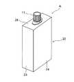
図1は本発明に係る注出口付き液体容器の一例を示す斜視図、図2は図1に示す注出口付き液体容器の構成部材を別々に示す斜視図である。 FIG. 1 is a perspective view showing an example of a liquid container with a spout according to the present invention, and FIG. 2 is a perspective view separately showing components of the liquid container with a spout shown in FIG.
図2に示すように、図1の注出口付き液体容器Aは、キャップ11を螺着する注出口が設けられた軟包装袋10と、軟包装袋10をその注出口が上部から突出する状態で収納する厚紙製の外箱20と、外箱20から突出した注出口の首部分に嵌合するシート状のストッパー40とからなる。別部材であるストッパー40は、図3により後述するように、外箱20に対して注出口13を回動不能な状態で固定するように注出口13の首部分17に嵌合するようになっている。 As shown in FIG. 2, the liquid container A with a spout of FIG. 1 includes a
軟包装袋10は、図3にその一部分を示すように、ガゼットタイプ或いはスタンディングパウチタイプの包装袋本体12の上部に注出口13を有し、その注出口13にキャップ11が螺着されたものである。注出口13は包装袋本体12の上部に挟持状態で取り付けられる外形が船形の取付板14を有しており、この取付板14の部分が包装袋本体12のシール部12aの内面に融着されるようになっている。そして、取付板14の上方には包装袋本体12の上端縁が当接するフランジ15とそれと平行なフランジ16とが所定の間隔を置いて設けられ、これら一対のフランジ15,16の間は首部分17となっており、その首部分17には平行面が形成されている。すなわち、注出口13には機械でハンドリングするために、水平な一対のフランジ15,16が設けられ、また向きを決めるためにそれらの間の首部分17は矩形状になっており、これによって首部分17には包装袋本体12の上端縁と直角方向に平行面が形成されている。なお、図示はしていないが、キャップ11としては、必要に応じて公知のピルファープルーフを付けたものを用いるようにしてもよい。 As shown in part of FIG. 3, the
外箱20は、図4に示すブランクBから組み立てられる。このブランクBは、板紙や段ボールシートなどの厚紙を打ち抜いたもので、図示のように、折線a,b,c,dを介して糊代片21、側面パネル22,23,24,25を順次連設している。 The
ブランクBにおける側面パネル22の上辺には中程に切込み線αのある折線eを介して内蓋パネル26を連設し、その内蓋パネルの上辺には折線fを介して差込み片26aを連設し、側面パネル23の上辺には折線gを介して折曲げ片27を連設し、側面パネル24の上辺には折線hを介して外蓋パネル28を連設し、その外蓋パネル28の上辺の中程には折線iを介して差込み凸部28aを連設し、側面パネル25の上辺には折線jを介して折曲げ片29を連設している。そして、内蓋パネル26と外蓋パネル28にはそれらの中央にそれぞれ開口26b,28bが形成されており、これらの開口26b,28bは注出口13のフランジ15,16より僅かに大きく、且つ、それぞれが差込み片26aと差込み凸部28aの方に丸く膨らんだ形状をしている。また、折曲げ片27,29の上端縁にはフランジ15,16の半分の形状をした切欠部27a,29aが形成されている。 An
また、側面パネル22の下辺には折線kを介して外折込み片30を連設し、側面パネル23の下辺には折線lを介して内折込み片31を連設し、側面パネル24の下辺には折線mを介して外折込み片32を連設し、側面パネル25の下辺には折線nを介して内折込み片33を連設しており、外折込み片30の一部の三角形部分を折線oで折り返せる糊代部分30aとし、外折込み片32の一部の三角形部分を折線pで折り返せる糊代部分32aとしている。 Further, an
なお、ブランクBの素材としては、板紙や段ボールシートの他に、これらを主体として樹脂フィルムなどを組み合わせた複合シートなどを使用することができ、特に限定されるものではない。 In addition, as a raw material of the blank B, the composite sheet etc. which combined the resin film etc. mainly by these other than a paperboard and a corrugated board sheet | seat etc. can be used, It does not specifically limit.
ストッパー40は、ブランクBと同じ素材又は別のシート状物を打ち抜いたもので、図5に示すような形状をしている。このストッパー40の横幅は内蓋パネル26及び外蓋パネル28とほぼ同じであり、縦方向の長さは内蓋パネル26及び外蓋パネル28とほぼ同じか少し短くなっている。そして、ストッパー40には、図示のように、四角形の中心部40aとそれに繋がる末広状の導入部40bとからなる切欠が形成されており、中心部40aは注出口13の首部分17が丁度嵌まるサイズになっている。 The
上記のブランクBはサック貼りして供給される。すなわち、外折込み片30を折線kで側面パネル22の裏面側に折り返し、内折込み片31を折線lで側面パネル23の裏面側に折り返し、外折込み片32を折線mで側面パネル24の裏面側に折り返し、内折込み片33を折線nで側面パネル25の裏面側に折り返す。そして、その外折込み片30の糊代部分30aを折線oで外側に折り返し、その外折込み片32の糊代部分32aを折線pで外側に折り返す。 The blank B is supplied with a sack. That is, the
次に、側面パネル22を折線bで側面パネル23の裏面側に折り返し、側面パネル25を折線dで側面パネル24の裏面側に折り返し、糊代片21と側面パネル25の側縁部の裏面とを貼り合わせる。同時に、外折込み片30の糊代部分30aと内折込み片31とを貼り合わせ、外折込み片32の糊代部分32aと内折込み片33とを貼り合わせる。このようにしてブランクBは折り畳まれてサック貼りした状態となり、この折り畳まれた状態で軟包装袋を収納する箱詰め工程へと供給される。 Next, the
箱詰め工程では、折り畳まれた状態の外箱20を起こすが、底部がオートロック式になっているので、起こすと同時に図2のように外箱20は底部が自動的に形成される。このように底部が形成された外箱20の中に軟包装袋10を入れる。そして、注出口13のフランジ15,16を切欠部27a,29aが囲むようにして両側の折曲げ片27,29を内側に折り曲げた後、内蓋パネル26を折り曲げる。この時、注出口13のフランジ15,16が開口26bを通るようにして内蓋パネル26を折り曲げ、差込み片26aを側面パネル24の裏側に差し込んで蓋をする。 In the boxing process, the
次いで、内蓋パネル26から露出しているフランジ15,16の間にストッパー40を挿入する。この時の内蓋パネル26とストッパー40の位置関係を示すと図6のようである。続いて、外蓋パネル28を折り曲げる。すなわち、注出口13のフランジ15,16が開口28bを通るようにして外蓋パネル28を折り曲げ、その先端の差込み凸部28aを内蓋パネル26の端縁にある切込み線αに差し込んで蓋をする。これにより図1に示す注出口付き液体容器Aが完成する。このようにして外箱20の中に軟包装袋10を収納すると、ストッパー40は外蓋パネル28により回動が阻止され、そのストッパー40により軟包装袋10の注出口13は回動が阻止された状態となる。 Next, the
この注出口付き液体容器Aは、軟包装袋10が外箱20の中に入っているので、立てた状態で置いておくことができ、軟包装袋10に収納した内容物の液体が減少しても立てることができる。そして、注出口13が外箱20から突出して回動不能な状態で固定されており、キャップ11を回した時に中の軟包装袋10が同時に回転しないので、キャップ11を確実に開閉することができる。 The liquid container A with a spout can be placed in an upright state because the
図7は本発明に係る注出口付き液体容器の別の例を示す斜視図であり、この注出口付き液体容器A’は、外箱20の側面パネル24に中が見えるスリット24aを設けたものであり、その以外の構成は先に説明した注出口付き液体容器Aと同じである。この注出口付き液体容器A’では、使用して中の液体が減ってきたときに、スリット24aから中を見ることよってその残量を確認することができる。なお、スリット24aの形状は任意であるし、いずれの側面パネルに設けてもよい。要は軟包装袋10の内容物の状態が見えるように設ければよいものである。 FIG. 7 is a perspective view showing another example of the liquid container with a spout according to the present invention. The liquid container A ′ with a spout is provided with a
以上、本発明の実施の形態について詳細に説明してきたが、本発明による注出口付き液体容器は、上記実施の形態に何ら限定されるものではなく、本発明の趣旨を逸脱しない範囲において種々の変更が可能であることは言うまでもない。 As mentioned above, although embodiment of this invention has been described in detail, the liquid container with spout according to the present invention is not limited to the above embodiment at all, and various kinds of liquid containers can be used without departing from the spirit of the present invention. It goes without saying that changes are possible.
A,A’ 注出口付き液体容器
B ブランク
a〜p 折線
α 切込み線
10 軟包装袋
11 キャップ
12 包装袋本体
12a シール部
13 注出口
14 取付板
15,16 フランジ
17 首部分
20 外箱
21 糊代片
22〜25 側面パネル
24a スリット
26 内蓋パネル
26a 差込み片
26b 開口
27 折曲げパネル
27a 切欠部
28 外蓋パネル
28a 差込み凸部
28b 開口
29 折曲げ片
29a 切欠部
30 外折込み片
30a 糊代部分
31 内折込み片
32 外折込み片
32a 糊代部分
33 内折込み片
40 ストッパー
40a 中心部
40b 導入部
A, A 'Liquid container with spout B Blank a-p Folded line
Claims (3)
Translated fromJapaneseThe liquid container with a spout according to claim 1 or 2, wherein a slit that allows the inside to be seen is provided on a side surface of the outer box.
Priority Applications (1)
| Application Number | Priority Date | Filing Date | Title |
|---|---|---|---|
| JP2006021659AJP4775008B2 (en) | 2006-01-31 | 2006-01-31 | Liquid container with spout |
Applications Claiming Priority (1)
| Application Number | Priority Date | Filing Date | Title |
|---|---|---|---|
| JP2006021659AJP4775008B2 (en) | 2006-01-31 | 2006-01-31 | Liquid container with spout |
Publications (2)
| Publication Number | Publication Date |
|---|---|
| JP2007204059Atrue JP2007204059A (en) | 2007-08-16 |
| JP4775008B2 JP4775008B2 (en) | 2011-09-21 |
Family
ID=38483868
Family Applications (1)
| Application Number | Title | Priority Date | Filing Date |
|---|---|---|---|
| JP2006021659AExpired - Fee RelatedJP4775008B2 (en) | 2006-01-31 | 2006-01-31 | Liquid container with spout |
Country Status (1)
| Country | Link |
|---|---|
| JP (1) | JP4775008B2 (en) |
Cited By (7)
| Publication number | Priority date | Publication date | Assignee | Title |
|---|---|---|---|---|
| JP2009179369A (en)* | 2008-01-31 | 2009-08-13 | Tenryu Kagaku Kogyo Kk | Stand for bag container |
| JP2011506026A (en)* | 2007-12-18 | 2011-03-03 | コーニンクレッカ フィリップス エレクトロニクス エヌ ヴィ | Protective assembly for compressed gas interdental cleaner |
| JP2011105341A (en)* | 2009-11-17 | 2011-06-02 | Kao Corp | Boxlike vessel |
| JP2011240996A (en)* | 2011-08-03 | 2011-12-01 | Kao Corp | Bag |
| WO2014014505A1 (en)* | 2012-07-17 | 2014-01-23 | Graphic Packaging International, Inc. | Carton with article protection flap |
| JP2015202875A (en)* | 2014-04-11 | 2015-11-16 | 旭化成パックス株式会社 | Outer container, filling container and bag-like container |
| JP2022166769A (en)* | 2021-04-21 | 2022-11-02 | 大日本印刷株式会社 | Composite container |
Citations (3)
| Publication number | Priority date | Publication date | Assignee | Title |
|---|---|---|---|---|
| JPS5291334A (en)* | 1976-01-26 | 1977-08-01 | Nec Corp | Multi-access memory method and memory chips therefor |
| JPS5882379A (en)* | 1981-11-11 | 1983-05-17 | Denki Onkyo Co Ltd | Lamicard |
| JP2000062813A (en)* | 1998-08-20 | 2000-02-29 | Dainippon Printing Co Ltd | Pouch with spout |
- 2006
- 2006-01-31JPJP2006021659Apatent/JP4775008B2/ennot_activeExpired - Fee Related
Patent Citations (3)
| Publication number | Priority date | Publication date | Assignee | Title |
|---|---|---|---|---|
| JPS5291334A (en)* | 1976-01-26 | 1977-08-01 | Nec Corp | Multi-access memory method and memory chips therefor |
| JPS5882379A (en)* | 1981-11-11 | 1983-05-17 | Denki Onkyo Co Ltd | Lamicard |
| JP2000062813A (en)* | 1998-08-20 | 2000-02-29 | Dainippon Printing Co Ltd | Pouch with spout |
Cited By (14)
| Publication number | Priority date | Publication date | Assignee | Title |
|---|---|---|---|---|
| JP2011506026A (en)* | 2007-12-18 | 2011-03-03 | コーニンクレッカ フィリップス エレクトロニクス エヌ ヴィ | Protective assembly for compressed gas interdental cleaner |
| JP2009179369A (en)* | 2008-01-31 | 2009-08-13 | Tenryu Kagaku Kogyo Kk | Stand for bag container |
| JP2011105341A (en)* | 2009-11-17 | 2011-06-02 | Kao Corp | Boxlike vessel |
| US9352890B2 (en) | 2011-05-06 | 2016-05-31 | Graphic Packaging International, Inc. | Carton with article protection insert |
| US10207848B2 (en) | 2011-05-06 | 2019-02-19 | Graphic Packaging International, Llc | Carton with article protection insert |
| US9073683B2 (en) | 2011-05-06 | 2015-07-07 | Graphic Packaging International, Inc. | Carton with article protection flap |
| US10029837B2 (en) | 2011-05-06 | 2018-07-24 | Graphic Packaging International, Llc | Carton with article protection insert |
| JP2011240996A (en)* | 2011-08-03 | 2011-12-01 | Kao Corp | Bag |
| WO2014014505A1 (en)* | 2012-07-17 | 2014-01-23 | Graphic Packaging International, Inc. | Carton with article protection flap |
| US10875693B2 (en) | 2012-07-17 | 2020-12-29 | Graphie Packaging International, LLC | Carton with article protection insert |
| US11760549B2 (en) | 2012-07-17 | 2023-09-19 | Graphic Packaging International, Llc | Carton with article protection insert |
| JP2015202875A (en)* | 2014-04-11 | 2015-11-16 | 旭化成パックス株式会社 | Outer container, filling container and bag-like container |
| JP2022166769A (en)* | 2021-04-21 | 2022-11-02 | 大日本印刷株式会社 | Composite container |
| JP7673477B2 (en) | 2021-04-21 | 2025-05-09 | 大日本印刷株式会社 | Composite Containers |
Also Published As
| Publication number | Publication date |
|---|---|
| JP4775008B2 (en) | 2011-09-21 |
Similar Documents
| Publication | Publication Date | Title |
|---|---|---|
| US8220701B2 (en) | Cartons, packages, blanks, and containers having dispensing and opening features | |
| JP4775008B2 (en) | Liquid container with spout | |
| US10959461B2 (en) | Display packages, blanks for forming trap seal card and blank for forming display box | |
| JP5955077B2 (en) | Packaging box | |
| JP5837666B1 (en) | Packaging box | |
| JPH04501098A (en) | Container for filling substances into a film bag consisting of a film bag inside a folding box | |
| JP7314560B2 (en) | package | |
| JP2011079528A (en) | Packaging container for fluid | |
| JP3952747B2 (en) | Food packaging | |
| US9248934B2 (en) | Reclosable packaging container for powder or granular materials | |
| JP3145639U (en) | Containment box flap lid jig | |
| JP6679831B2 (en) | Packaging container | |
| JP5380716B2 (en) | Pouch container with spout | |
| JP2562652Y2 (en) | Liquid paper container | |
| JP7216498B2 (en) | packaging container | |
| JP5333052B2 (en) | One-touch container | |
| JP2010023884A (en) | carton | |
| JPS5846040Y2 (en) | Housoutai | |
| JP4813316B2 (en) | carton | |
| CN205633346U (en) | From packing carton that opens and shuts | |
| JP7146368B2 (en) | bag-in-box and blank sheet | |
| JP6497074B2 (en) | Packaging container | |
| JP6313346B2 (en) | Double packing packaging box and double packing method using the same | |
| JP2023039124A (en) | paper container | |
| JP6011236B2 (en) | Attached paper box for gable roof pattern paper container |
Legal Events
| Date | Code | Title | Description |
|---|---|---|---|
| A621 | Written request for application examination | Free format text:JAPANESE INTERMEDIATE CODE: A621 Effective date:20081023 | |
| A977 | Report on retrieval | Free format text:JAPANESE INTERMEDIATE CODE: A971007 Effective date:20101028 | |
| A131 | Notification of reasons for refusal | Free format text:JAPANESE INTERMEDIATE CODE: A131 Effective date:20110225 | |
| A521 | Written amendment | Free format text:JAPANESE INTERMEDIATE CODE: A523 Effective date:20110411 | |
| TRDD | Decision of grant or rejection written | ||
| A01 | Written decision to grant a patent or to grant a registration (utility model) | Free format text:JAPANESE INTERMEDIATE CODE: A01 Effective date:20110531 | |
| A01 | Written decision to grant a patent or to grant a registration (utility model) | Free format text:JAPANESE INTERMEDIATE CODE: A01 | |
| A61 | First payment of annual fees (during grant procedure) | Free format text:JAPANESE INTERMEDIATE CODE: A61 Effective date:20110613 | |
| R150 | Certificate of patent or registration of utility model | Ref document number:4775008 Country of ref document:JP Free format text:JAPANESE INTERMEDIATE CODE: R150 Free format text:JAPANESE INTERMEDIATE CODE: R150 | |
| FPAY | Renewal fee payment (event date is renewal date of database) | Free format text:PAYMENT UNTIL: 20140708 Year of fee payment:3 | |
| LAPS | Cancellation because of no payment of annual fees |