JP2007203771A - Vehicle steering column device - Google Patents
Vehicle steering column deviceDownload PDFInfo
- Publication number
- JP2007203771A JP2007203771AJP2006021814AJP2006021814AJP2007203771AJP 2007203771 AJP2007203771 AJP 2007203771AJP 2006021814 AJP2006021814 AJP 2006021814AJP 2006021814 AJP2006021814 AJP 2006021814AJP 2007203771 AJP2007203771 AJP 2007203771A
- Authority
- JP
- Japan
- Prior art keywords
- collar
- bearing
- steering
- key lock
- shaft
- Prior art date
- Legal status (The legal status is an assumption and is not a legal conclusion. Google has not performed a legal analysis and makes no representation as to the accuracy of the status listed.)
- Pending
Links
Images


Landscapes
- Steering Controls (AREA)
Abstract
Translated fromJapaneseDescription
Translated fromJapanese本発明は、ステアリングロック装置を備えた車両用ステアリングコラム装置に関するものである。 The present invention relates to a vehicle steering column device provided with a steering lock device.
車両用ステアリングコラム装置は、筒状のコラムジャケット内にステアリングシャフトを回転可能に挿通支持せしめ、該ステアリングシャフトの一端にステアリングホイールを取り付け、同ステアリングシャフトの他端を操舵系に連結して構成されている。 A vehicle steering column device is configured such that a steering shaft is rotatably inserted and supported in a cylindrical column jacket, a steering wheel is attached to one end of the steering shaft, and the other end of the steering shaft is connected to a steering system. ing.
ところで、斯かる車両用ステアリングコラム装置には、車両の盗難防止を目的として、駐停車時にステアリングホイールの回転をロックするためのステアリングロック装置が設けられている。このステアリングロック装置としては、ドライバが所有する発信器からの信号を受信して作動する電動アクチュエータ式のものが主流となりつつあり、このような電動アクチュエータ式のステアリングロック装置は、電動アクチュエータによってロックピンを進退動させることができ、ロックピンの進退動を従来のメカ式のようにイグニッションキーの回動に連動させる必要がないため、ステアリングハンドルの近傍に配置されているイグニッション用キーシリンダと切り離して別途配置することができる。 By the way, such a steering column device for a vehicle is provided with a steering lock device for locking the rotation of the steering wheel at the time of parking and stopping for the purpose of preventing theft of the vehicle. As such a steering lock device, an electric actuator type which operates by receiving a signal from a transmitter owned by a driver is becoming mainstream. Such an electric actuator type steering lock device is locked by an electric actuator. Since the lock pin does not need to be interlocked with the rotation of the ignition key as in the conventional mechanical type, it can be separated from the ignition key cylinder located near the steering handle. It can be arranged separately.
上述のように電動アクチュエータ式のステアリングロック装置は、電動アクチュエータによってロックピンを進退動させるが、ステアリングシャフトにはロックピンが選択的に係合するためのキーロックカラーが例えば溶接によって固定されている(特許文献1参照)。 As described above, the steering lock device of the electric actuator type moves the lock pin forward and backward by the electric actuator, but a key lock collar for selectively engaging the lock pin is fixed to the steering shaft by welding, for example. (See Patent Document 1).
他方、ステアリングシャフトをコラムジャケットに対して回転可能に支持するベアリングには市販品が使用され、その寸法は予め決定されているため、該ベアリングの寸法に合わせてステアリングシャフトの外周に寸法調整用のスペーサとしてのベアリングカラーが溶接又は圧入によって固定されている(特許文献2参照)。 On the other hand, a commercially available product is used for the bearing that rotatably supports the steering shaft with respect to the column jacket, and the dimensions thereof are determined in advance. A bearing collar as a spacer is fixed by welding or press fitting (see Patent Document 2).
ところで、電動アクチュエータ式のステアリングロック装置を備えた車両用ステアリングコラム装置においては、車両レイアウト等により、ステアリングロック装置を反ステアリングホイール側のロアベアリングの近傍に設ける場合がある。このような場合、キーロックカラーとベアリングカラーは別体として構成され、前述のように、キーロックカラーはステアリングシャフトに溶接によって固定され、ベアリングカラーはステアリングシャフトに溶接又は圧入によって固定されていた。
しかしながら、ベアリングカラーをステアリングシャフトに溶接又は圧入すると、その外周が変形するため、外周面を研磨加工して該ベアリングカラーに高い真円度を確保する必要があり、後加工が必要であるためにコストアップを招く原因となる。因に、ベアリングカラーの外周が変形してその真円度が低下すると、キーロックカラーが振れてコラムジャケットと干渉する可能性がある。 However, if the bearing collar is welded or press-fitted to the steering shaft, its outer periphery will be deformed, so it is necessary to polish the outer peripheral surface to ensure high roundness of the bearing collar, and post-processing is necessary. This causes an increase in cost. If the outer circumference of the bearing collar is deformed and its roundness is lowered, the key lock collar may swing and interfere with the column jacket.
又、キーロックカラーとベアリングカラーの組み付けに際しては、ステアリングシャフトの反ステアリングホイール側にはヨークが固定されているため、ステアリングホイール側から組み付けることになる。更に、キーロックカラーの外径がロアベアリングの内径よりも大きいため、ステアリングホイール側からベアリングカラーをシャフトに挿入し、その後、ベアリングカラーをステアリングシャフトの反ステアリングホイール側に溶接又は圧入した後、ロアベアリングを組み込み、最後にキーロックカラーをステアリングホイール側からステアリングシャフトに通して溶接によって固定する必要がある。このようにキーロックカラーを最後に溶接によってステアリングシャフトに固定すると、ロアベアリングのグリースが溶接熱によって劣化する恐れがある。 Further, when assembling the key lock collar and the bearing collar, since the yoke is fixed to the side opposite to the steering wheel of the steering shaft, it is assembled from the steering wheel side. Furthermore, since the outer diameter of the key lock collar is larger than the inner diameter of the lower bearing, the bearing collar is inserted into the shaft from the steering wheel side, and then the bearing collar is welded or press-fitted to the anti-steering wheel side of the steering shaft. It is necessary to incorporate the bearing and finally fix the key lock collar by welding through the steering shaft from the steering wheel side. When the key lock collar is finally fixed to the steering shaft by welding as described above, the grease of the lower bearing may be deteriorated by welding heat.
又、別体のキーロックカラーとベアリングカラーを別々に組み付けると、組み付けに手間が掛かって組付工数が増えるとともに、キーロックカラーとベアリングカラーそれぞれの寸法精度を高く保つことが困難であるという問題もある。 Also, if separate key lock collar and bearing collar are assembled separately, it takes time to assemble and increases the number of assembly steps, and it is difficult to maintain high dimensional accuracy of each of the key lock collar and bearing collar. There is also.
本発明は上記問題に鑑みてなされたもので、その目的とする処は、研磨加工等の後加工が不要で、熱によるベアリングのグリース等の劣化を防ぎつつ、部品点数を削減して組み付けの容易化と組付工数の削減及び寸法精度の向上を図ることができる車両用ステアリングコラム装置を提供することにある。 The present invention has been made in view of the above-mentioned problems, and the intended process is that post-processing such as polishing is not required, and it is possible to reduce the number of components while preventing deterioration of bearing grease due to heat. It is an object of the present invention to provide a steering column device for a vehicle that can facilitate, reduce the number of assembly steps, and improve dimensional accuracy.
上記目的を達成するため、請求項1記載の発明は、コラムジャケット内にベアリングを介して回転可能に挿通支持されたステアリングシャフトの一端を操舵系に連結し、該ステアリングシャフトにキーロックカラーとベアリングカラーを挿通固定するとともに、前記キーロックカラーに選択的に係合するロックピンを備えた電動アクチュエータを設けて成る車両用ステアリングコラム装置において、前記キーロックカラーとベアリングカラーとをカラー部品として一体成形し、該カラー部品のキーロックカラー部をスリップリングを介して前記ステアリングシャフトに嵌着したことを特徴とする。 In order to achieve the above object, according to the present invention, one end of a steering shaft rotatably inserted and supported via a bearing in a column jacket is connected to a steering system, and a key lock collar and a bearing are connected to the steering shaft. In a vehicle steering column device that is provided with an electric actuator having a lock pin that is inserted and fixed to the key lock collar and selectively engages with the key lock collar, the key lock collar and the bearing collar are integrally formed as a color part. The key lock collar portion of the collar part is fitted to the steering shaft via a slip ring.
請求項2記載の発明は、請求項1記載の発明において、前記カラー部品のベアリングカラー部の外周と前記ベアリングの内周との間にOリングを介設したことを特徴とする。 The invention according to
本発明によれば、従来は別体の独立した部品として構成されていたキーロックカラーとベアリングカラーとを一体成形によってカラー部品として一体化したため、部品点数が削減され、該カラー部品の組み付けの容易化と組付工数の削減が図られる。更に、余分な後加工も不要となり、コストの削減が図られる。 According to the present invention, since the key lock collar and the bearing collar, which have been conventionally configured as separate and independent parts, are integrated as a color part by integral molding, the number of parts is reduced and the color part can be easily assembled. And reduction of assembly man-hours. Furthermore, unnecessary post-processing is not necessary, and the cost can be reduced.
又、カラー部品のステアリングシャフトへの組付手段に溶接を用いないため、ベアリングのグリースが溶接熱によって劣化することがなく、その耐久性の向上が図られる。 Further, since welding is not used as a means for assembling the collar part to the steering shaft, the grease of the bearing is not deteriorated by welding heat, and the durability is improved.
更に、ベアリングカラー部とキーロックカラー部を一体化することによって、カラー内周の寸法精度が向上するため、ステアリングシャフトに対する真円度が高められ、該ステアリングシャフトに嵌着されたカラー部品のキーロックカラー部が振れてコラムジャケットと干渉する等の不具合が発生することがない。 Furthermore, by integrating the bearing collar part and the key lock collar part, the dimensional accuracy of the inner circumference of the collar is improved, so the roundness with respect to the steering shaft is increased, and the key of the color part fitted to the steering shaft is increased. There is no problem such as the lock collar swinging and interfering with the column jacket.
又、本発明によれば、カラー部品のベアリングカラー部の外周とベアリングの内周との間にOリングを介設したため、ベアリングとステアリングシャフトの間をOリングを介して嵌合することとなり、ベアリングカラー部の外周の寸法精度がラフにでき、組付性が向上する。 Further, according to the present invention, since the O-ring is interposed between the outer periphery of the bearing collar portion of the collar part and the inner periphery of the bearing, the bearing and the steering shaft are fitted via the O-ring. The dimensional accuracy of the outer periphery of the bearing collar can be made rough, and the assemblability is improved.
以下に本発明の実施の形態を添付図面に基づいて説明する。 Embodiments of the present invention will be described below with reference to the accompanying drawings.
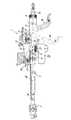
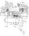
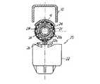
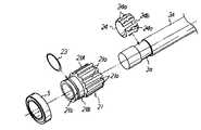
図1は本発明に係る車両用ステアリングコラム装置の破断側面図、図2は図1の要部拡大詳細図、図3は図2のA−A線断面図、図4は図2のB−B線断面図、図5は図2のC−C線断面図、図6はカラー部品を含む各種部品のステアリングシャフトへの組付構造を示す分解斜視図である。 1 is a cutaway side view of a steering column device for a vehicle according to the present invention, FIG. 2 is an enlarged detail view of an essential part of FIG. 1, FIG. 3 is a cross-sectional view taken along line AA in FIG. FIG. 5 is a cross-sectional view taken along line C-C in FIG. 2, and FIG. 6 is an exploded perspective view showing a structure for assembling various parts including collar parts to the steering shaft.
図1に示す車両用ステアリングコラム装置1において、2は円筒状のコラムジャケットであって、その内部にはステアリングシャフト3のアッパシャフト3Aが回転可能に挿通しており、当該ステアリングコラム装置1は、図1の左方(車体前方)を下にして車体側に所定角度傾斜して斜めに取り付けられている。ここで、アッパシャフト3Aは、その軸方向両端部(上下端)がアッパベアリング4とロアベアリング5によってコラムジャケット2に回転可能に支持され、その一端(上端)には不図示のステアリングホイールが結着されている。 In the vehicle steering column apparatus 1 shown in FIG. 1,
ところで、本実施の形態に係る車両用ステアリングコラム装置1は、ステアリングホイールの上下の高さ位置を調整可能なチルト機能と、同ステアリングホイールの軸方向位置を調整可能なテレスコピック機能を備えており、前記ステアリングシャフト3は、前記アッパシャフト3Aと、該アッパシャフト3Aの下端にユニバーサルジョイント6を介して連結された中空状の中間軸3Bと、該中間軸3Bに軸方向移動可能にスプライン嵌合されたロアシャフト3Cとで構成されている。そして、ロアシャフト3Cの下端は、ユニバーサルジョイント7を介してパワーステアリング装置等の不図示の操舵系に連結されている。 Incidentally, the vehicle steering column apparatus 1 according to the present embodiment includes a tilt function capable of adjusting the vertical position of the steering wheel and a telescopic function capable of adjusting the axial position of the steering wheel. The steering shaft 3 is spline-fitted to the
又、図2〜4に示すように、コラムジャケット2の軸方向中間上部と下端上部には断面U字状のディスタンスブラケット8とテレスコブラケット9がそれぞれ結着されており、これらのディスタンスブラケット8とテレスコブラケット9の両側部には軸方向に長いテレスコピック溝8aとテレスコピック孔9aがそれぞれ形成されている。 As shown in FIGS. 2 to 4, a distance bracket 8 and a
他方、車体側には断面逆U字状のサポートブラケット10がアッパブラケット11とロアブラケット12を介して取り付けられており、このサポートブラケット10の内側には、コラムジャケット2に結着された前記ディスタンスブラケット8とテレスコブラケット9が嵌合保持されている。そして、図2及び図4に示すように、テレスコブラケット9は、これに形成されたテレスコピック孔9aに挿通するピン13を中心としてサポートブラケット10の下端部に上下回動可能に枢着されている。 On the other hand, a
又、図2及び図3に示すように、サポートブラケット10のディスタンスブラケット8が嵌合する部位の両側部には上下方向に長いチルト孔10aがそれぞれ形成されており、これらのチルト孔10aとディスタンスブラケット8に形成されたテレスコピック溝8aにはクランプボルト14が横方向に挿通している。そして、クランプボルト14の一端(図3の右端)と前記アッパブラケット11との間にはリターンスプリング15が介装されており、このリターンスプリング15によってディスタンスブラケット8、コラムジャケット2とこれに挿通保持されたアッパシャフト3A及び該アッパシャフト3Aに結着された不図示のステアリングホイールが前記ピン13を中心として上方に付勢されている。 As shown in FIGS. 2 and 3, tilt holes 10a that are long in the vertical direction are formed on both sides of the portion of the
更に、前記クランプボルト14の他端(図4の左端)には操作レバー16がフランジナット17によって結着されており、該操作レバー16とサポートブラケット10との間には、操作レバー16側に固定されたカム部材18とサポートブラケット10側に固定されたカム部材19が設けられており、両カム部材18,19に形成されたカム同士は互いに係合している。 Further, an
而して、操作レバー16が図1の実線位置にあるときには、前記両カム部材18,19のカムの山同士が係合しているためにクランプボルト14に軸方向の引張力が作用し、この引張力によってサポートブラケット10とディスタンスブラケット8とが締め付けられるため、両者間に大きな摩擦力が発生し、コラムジャケット2とアッパシャフト3A及びステアリングホイールの上下方向の回動と軸方向の移動がロックされる。 Thus, when the
而して、ステアリングホイールの上下方向の高さ位置調整(チルト調整)及び軸方向の位置調整(テレスコピック調整)を行う場合には、操作レバー16を図1の破線位置まで回す。すると、両カム部材18,19のカムの山と谷同士が係合するため、クランプボルト14に作用していた軸方向の引張力が開放されてコラムジャケット2とアッパシャフト3A及びステアリングホイールの上下方向の回動と軸方向の移動のロックが解除される。 Thus, when adjusting the vertical position (tilt adjustment) and the axial position (telescopic adjustment) of the steering wheel, the
従って、チルト調整を行う場合には、コラムジャケット2とアッパシャフト3A及びステアリングホイールを車体に対してピン13を中心として上下に回動させることによって、クランプボルト14がサポートブラケット10のチルト孔10a内を移動し得る範囲で、ステアリングホイールの上下方向の高さ位置を調整することができる。 Therefore, when tilt adjustment is performed, the
又、テレスコピック調整を行う場合には、クランプボルト14とピン13がディスタンスブラケット8のテレスコピック溝8aとテレスコブラケット9のテレスコピック孔9a内を軸方向に移動し得る範囲で、ステアリングホイールの軸方向位置を調整することができる。このとき、ステアリングシャフト3のロアシャフト3Cは不動であって、これにスプライン嵌合する中間軸3Bとユニバーサルジョイント6を介して中間軸3Bに連結されたアッパシャフト3A及びこれを支持するコラムジャケット2がロアシャフト3Cに対して軸方向に移動する。 When telescopic adjustment is performed, the axial position of the steering wheel is adjusted within a range in which the
以上のようにチルト調整又は/及びテレスコピック調整を行った後に操作レバー16を図1の実線位置まで回すと、コラムジャケット2とアッパシャフト3A及びステアリングホイールの上下方向の回動と軸方向の移動が再びロックされる。 When the
而して、ドライバが不図示のステアリングホイールを左右に回動操作すると、その回転はステアリングシャフト3(アッパシャフト3Aと中間軸3B及びロアシャフト3C)及びユニバーサルジョイント7を経て不図示の操舵系に伝達され、不図示の前輪が左右に転舵されて車両の左右何れかの方向のコーナリングがなされる。 Thus, when the driver rotates the steering wheel (not shown) to the left and right, the rotation is transferred to the steering system (not shown) via the steering shaft 3 (
ところで、本実施の形態に係る車両用ステアリングコラム装置1においては、車両の盗難防止を目的として、駐停車時にステアリングホイールの回転をロックするためのステアリングロック装置20がロアベアリング5の近傍に設けられている(図2参照)
本実施の形態に係るステアリングロック装置20は、ドライバが所有する発信器からの信号を受信して作動する電動アクチュエータ式のものであって、アッパシャフト3Aのロアベアリング5の近傍に挿通固着されたカラー部品21と、該カラー部品21に選択的に係合するロックピン22aを備えた電動アクチュエータ22を備えている。By the way, in the vehicle steering column device 1 according to the present embodiment, a
The
ここで、カラー部品21は、従来は別体の独立した部品として構成されていたキーロックカラーとベアリングカラーとを一体成形によって一体化して1部品として構成されており、図6にも示すように、これにはキーロックカラー部21Aとベアリングカラー部21Bが設けられている。 Here, the
カラー部品21のキーロックカラー部21Aの外周には、図5及び図6に示すように、スプライン溝状の複数のロック溝21aが全周に亘って等角度ピッチで軸方向に貫設されており、その外径はベアリングカラー部21Bの外径及びロアベアリング5の内径よりも大きく設定されている。 As shown in FIGS. 5 and 6, a plurality of spline groove-
又、カラー部品21のベアリングカラー部21Bは、スペーサとして機能するものであって、その外周には溝21bが全周に亘って形成されており、この溝21bにはOリング23が嵌着されている。 Further, the
他方、アッパシャフト3Aのロアベアリング5近傍の外周には、所定幅の溝3aが全周に亘って形成されており、この溝3aにはスリップリング24が嵌着されている。ここで、スリップリング24は、図6に示すように、波板を円形に丸めて構成され、その外周にはフリクション調整用の複数の波状凸部24aが形成され、一部にスリット24bが形成されている。 On the other hand, a
又、前記電動アクチュエータ22は、ドライバが所有する発信器からの信号を受信して作動するものであって、図2及び図5に示すように、そのロックピン22aは、カラー部品21のキーロックカラー部21Aに対向配置されており、コラムジャケット2にはロックピン22aが通過するための貫通孔2aが形成されている。 The
以上のステアリングロック装置20を構成するカラー部品21は、次の要領でアッパシャフト3Aに組み付けられる。 The
図1に示すように、アッパシャフト3Aの反ステアリングホイール側の下端部にはユニバーサルジョイント6が既に取り付けられているため、カラー部品21はアッパシャフト3Aにステアリングホイール側(上方)から通されるが、それ以前にアッパシャフト3Aの溝3aにはスリップリング24が嵌着される。又、カラー部品21のベアリングカラー部21Aの外周にはロアベアリング5が予め組み込まれており、カラー部品21のベアリングカラー部21Bの外周に形成された溝21bとロアベアリング5の内周との間にはOリング23が介設されている。 As shown in FIG. 1, since the
而して、ロアベアリング5が組み付けられたカラー部品21は、アッパシャフト3Aにステアリングホイール側(上方)から通され、そのキーロックカラー部21Aの部分に、スリップリング24を介してアッパシャフト3Aに圧入によって嵌着される。ここで、カラー部品21のキーロックカラー部21Aはスリップリング24に圧入されるが、ステアリングホイールからアッパシャフト3Aに設定値以上の過大なトルクが作用すると、アッパシャフト3Aとスリップリング24がキーロックカラー部21Aに対して滑って回転することができる程度のフリクションがスリップリング24とキーロックカラー部21Aとの間に付与されている。尚、本実施の形態では、アッパシャフト3Aに過大なトルクが作用した場合に該アッパシャフト3Aとスリップリング24が回転を開始するフリクションは、専らスリップリング24によって決定され、その大きさは前述のようにスリップリング24の波状凸部24aによって調整される。 Thus, the
次に、ステアリングロック装置20の作用について説明する。 Next, the operation of the
車両の走行中はステアリングロック装置20はOFF状態にあり、電動アクチュエータ22のロックピン22aは、図2に示すように退避状態にあって、カラー部品21のキーロックカラー部21Aのロック溝21aに対して非係合状態を維持している。従って、この状態ではアッパシャフト3A及びステアリングホイールの回転を拘束するものは存在せず、ドライバはステアリングホイールを自由に回して所期のステアリング操作を行うことができる。 While the vehicle is running, the
そして、車両を駐停車した場合には、ドライバは自ら所有する発信器によってロック信号を発信すると電動アクチュエータ22が作動し、そのロックピン22aがコラムジャケット2の貫通孔2aを通過してコラムジャケット2内へと突出し、図5に示すように、カラー部品21のキーロックカラー部21Aのロック溝21aの1つに係合するため、ステアリングロック装置20がON状態となる。従って、この状態ではアッパシャフト3A及びステアリングホイールの回転がロックされてステアリング操作が不可能となり、車両の駐停車時の盗難が防がれる。 When the vehicle is parked or stopped, when the driver transmits a lock signal by a transmitter owned by the driver, the
又、ステアリングロック装置20がON状態にあって、ステアリングホイールの回転がロックされている状態において、ステアリングホイールが強引に回されたためにアッパシャフト3Aに設定値以上の過大なトルクが作用した場合には、前述のようにカラー部品21はそのまま静止した状態で、該カラー部品21に対してアッパシャフト3Aとスリップリング24が滑って回転するため、電動アクチュエータ22のロックピン22aの折損等が防がれ、ステアリングロック装置20をそのまま継続して使用することができる。 Also, when the
以上のように、本実施の形態に係る車両用ステアリングコラム装置1においては、従来は別体の独立した部品として構成されていたキーロックカラー部21Aとベアリングカラー部21Bとを一体成形によってカラー部品21として一体化したため、部品点数が削減され、該カラー部品21の組み付けの容易化と組付工数の削減及び寸法精度の向上が図られる。更に、余分な後加工も不要となり、コストの削減が図られる。 As described above, in the vehicle steering column apparatus 1 according to the present embodiment, the key
又、カラー部品21のアッパシャフト3Aへの組付手段に溶接を用いないため、ロアベアリング5のグリースやOリング23が溶接熱によって劣化することがなく、これらの耐久性向上が図られる。更に、キーロックカラー部21Aとベアリングカラー部21Bとを一体化することによって、カラー部品21の内周の寸法精度が向上するため、アッパシャフト3Aに対する真円度が高められ、該アッパシャフト3Aに嵌着されたカラー部品21のキーロックカラー部21Aが振れてコラムジャケット2と干渉する等の不具合が発生することがない。 Further, since welding is not used as a means for assembling the
その他、本実施の形態では、カラー部品21のベアリングカラー部21Bの外周に形成された溝21bとロアベアリング5の内周との間にOリング23を介して嵌合させるため、ベアリングカラー部21Bの外周寸法がラフにでき、組付性が向上する。 In addition, in the present embodiment, the
本発明は、ステアリングロック装置を備える車両用ステアリングコラム装置全般に対して適用可能であって、チルト機能やテレスコピック機能を備えるか否かは問わない。 The present invention can be applied to all vehicle steering column devices including a steering lock device, and it does not matter whether a tilt function or a telescopic function is provided.
1 車両用ステアリングコラム装置
2 コラムシャフト
2a 貫通孔
3 ステアリングシャフト
3A アッパシャフト
3B 中間軸
3C ロアシャフト
4 アッパベアリング
5 ロアベアリング
6,7 ユニバーサルジョイント
8 ディスタンスブラケット
8a テレスコピック溝
9 テレスコブラケット
9a テレスコピック孔
10 サポートブラケット
10a チルト孔
11 アッパブラケット
12 ロアブラケット
13 ピン
14 クランプボルト
15 リターンスプリング
16 操作レバー
17 フランジナット
18,19 カム部材
20 ステアリングロック装置
21 カラー部品
21A キーロックカラー部
21a ロック溝
21B ベアリングカラー部
21b 溝
22 電動アクチュエータ
22a ロックピン
23 Oリング
24 スリップリング
24a 波状凸部
24b スリットDESCRIPTION OF SYMBOLS 1 Vehicle
Claims (2)
Translated fromJapanese前記キーロックカラーとベアリングカラーとをカラー部品として一体成形し、該カラー部品のキーロックカラー部をスリップリングを介して前記ステアリングシャフトに嵌着したことを特徴とする車両用ステアリングコラム装置。One end of a steering shaft that is rotatably inserted and supported via a bearing in the column jacket is connected to the steering system, and a key lock collar and a bearing collar are inserted and fixed to the steering shaft, and the key lock collar is selectively used. In a vehicle steering column device provided with an electric actuator having a lock pin to be engaged,
A vehicle steering column device, wherein the key lock collar and the bearing collar are integrally formed as a color part, and the key lock collar portion of the color part is fitted to the steering shaft via a slip ring.
2. The vehicle steering column device according to claim 1, wherein an O-ring is interposed between an outer periphery of the bearing collar portion of the collar part and an inner periphery of the bearing.
Priority Applications (1)
| Application Number | Priority Date | Filing Date | Title |
|---|---|---|---|
| JP2006021814AJP2007203771A (en) | 2006-01-31 | 2006-01-31 | Vehicle steering column device |
Applications Claiming Priority (1)
| Application Number | Priority Date | Filing Date | Title |
|---|---|---|---|
| JP2006021814AJP2007203771A (en) | 2006-01-31 | 2006-01-31 | Vehicle steering column device |
Publications (1)
| Publication Number | Publication Date |
|---|---|
| JP2007203771Atrue JP2007203771A (en) | 2007-08-16 |
Family
ID=38483626
Family Applications (1)
| Application Number | Title | Priority Date | Filing Date |
|---|---|---|---|
| JP2006021814APendingJP2007203771A (en) | 2006-01-31 | 2006-01-31 | Vehicle steering column device |
Country Status (1)
| Country | Link |
|---|---|
| JP (1) | JP2007203771A (en) |
Cited By (8)
| Publication number | Priority date | Publication date | Assignee | Title |
|---|---|---|---|---|
| JP2011105267A (en)* | 2009-11-20 | 2011-06-02 | Honda Motor Co Ltd | Steering column device |
| JP2012158290A (en)* | 2011-02-02 | 2012-08-23 | Nsk Ltd | Electric power steering device |
| JP2012201169A (en)* | 2011-03-24 | 2012-10-22 | Nsk Ltd | Steering lock device |
| JP2014156225A (en)* | 2013-02-18 | 2014-08-28 | Aisin Seiki Co Ltd | Vehicle steering device |
| US8882146B2 (en) | 2011-02-02 | 2014-11-11 | Nsk Ltd. | Column unit for an electric power steering apparatus |
| JP2015039947A (en)* | 2013-08-21 | 2015-03-02 | 日本精工株式会社 | Steering device |
| JP2015039948A (en)* | 2013-08-21 | 2015-03-02 | 日本精工株式会社 | Steering device |
| US9266502B2 (en)* | 2012-11-26 | 2016-02-23 | Nsk Ltd. | Steering apparatus |
- 2006
- 2006-01-31JPJP2006021814Apatent/JP2007203771A/enactivePending
Cited By (9)
| Publication number | Priority date | Publication date | Assignee | Title |
|---|---|---|---|---|
| JP2011105267A (en)* | 2009-11-20 | 2011-06-02 | Honda Motor Co Ltd | Steering column device |
| JP2012158290A (en)* | 2011-02-02 | 2012-08-23 | Nsk Ltd | Electric power steering device |
| US8882146B2 (en) | 2011-02-02 | 2014-11-11 | Nsk Ltd. | Column unit for an electric power steering apparatus |
| JP2012201169A (en)* | 2011-03-24 | 2012-10-22 | Nsk Ltd | Steering lock device |
| US9266502B2 (en)* | 2012-11-26 | 2016-02-23 | Nsk Ltd. | Steering apparatus |
| JP2016155550A (en)* | 2012-11-26 | 2016-09-01 | 日本精工株式会社 | Steering device |
| JP2014156225A (en)* | 2013-02-18 | 2014-08-28 | Aisin Seiki Co Ltd | Vehicle steering device |
| JP2015039947A (en)* | 2013-08-21 | 2015-03-02 | 日本精工株式会社 | Steering device |
| JP2015039948A (en)* | 2013-08-21 | 2015-03-02 | 日本精工株式会社 | Steering device |
Similar Documents
| Publication | Publication Date | Title |
|---|---|---|
| US10676126B2 (en) | Rotation control assembly for a steering column | |
| JP5708838B2 (en) | Steering device | |
| JP2007203771A (en) | Vehicle steering column device | |
| US10279833B2 (en) | Cam device and position adjustment device for steering wheel | |
| EP2987700B1 (en) | Steering device | |
| US20180065656A1 (en) | Damping coupler of electronic power steering apparatus | |
| US6726228B2 (en) | Steering wheel alignment system | |
| WO2012066900A1 (en) | Support device for steering column | |
| WO2013187124A1 (en) | Steering lock device | |
| KR100746665B1 (en) | Tilt steering with radial fixed gear | |
| CN112969626B (en) | Steering shaft for a steering column of a motor vehicle and a steering column for a motor vehicle | |
| JP2009035104A (en) | Steering device | |
| WO2014170991A1 (en) | Steering lock device | |
| JP2000318626A (en) | Electric power steering device | |
| US20230174140A1 (en) | Steering rack bending limiter and steering assembly therewith | |
| KR20140135328A (en) | Locking System of Steering Shaft for Vehicle | |
| JP2008126750A (en) | Steering device | |
| KR101189304B1 (en) | The Rack Bar Supporting Device | |
| JP2015051655A (en) | Steering device | |
| JP5983893B2 (en) | Steering device | |
| JP2010116042A (en) | Electric tilt type steering device | |
| JP4817007B2 (en) | Steering device | |
| JP4952099B2 (en) | Lock mechanism | |
| WO2005123485A1 (en) | Steering device for vehicle and method of assembling the same | |
| JP2003034256A (en) | Electric power steering device |