JP2007203092A - Insertion kit - Google Patents
Insertion kitDownload PDFInfo
- Publication number
- JP2007203092A JP2007203092AJP2007079820AJP2007079820AJP2007203092AJP 2007203092 AJP2007203092 AJP 2007203092AJP 2007079820 AJP2007079820 AJP 2007079820AJP 2007079820 AJP2007079820 AJP 2007079820AJP 2007203092 AJP2007203092 AJP 2007203092A
- Authority
- JP
- Japan
- Prior art keywords
- sensor
- patient
- control unit
- analyte
- data
- Prior art date
- Legal status (The legal status is an assumption and is not a legal conclusion. Google has not performed a legal analysis and makes no representation as to the accuracy of the status listed.)
- Granted
Links
Images


Classifications
- A—HUMAN NECESSITIES
- A61—MEDICAL OR VETERINARY SCIENCE; HYGIENE
- A61B—DIAGNOSIS; SURGERY; IDENTIFICATION
- A61B5/00—Measuring for diagnostic purposes; Identification of persons
- A61B5/145—Measuring characteristics of blood in vivo, e.g. gas concentration or pH-value ; Measuring characteristics of body fluids or tissues, e.g. interstitial fluid or cerebral tissue
- A61B5/1495—Calibrating or testing of in-vivo probes
- A—HUMAN NECESSITIES
- A61—MEDICAL OR VETERINARY SCIENCE; HYGIENE
- A61B—DIAGNOSIS; SURGERY; IDENTIFICATION
- A61B5/00—Measuring for diagnostic purposes; Identification of persons
- A61B5/0002—Remote monitoring of patients using telemetry, e.g. transmission of vital signals via a communication network
- A61B5/0015—Remote monitoring of patients using telemetry, e.g. transmission of vital signals via a communication network characterised by features of the telemetry system
- A61B5/0022—Monitoring a patient using a global network, e.g. telephone networks, internet
- A—HUMAN NECESSITIES
- A61—MEDICAL OR VETERINARY SCIENCE; HYGIENE
- A61B—DIAGNOSIS; SURGERY; IDENTIFICATION
- A61B5/00—Measuring for diagnostic purposes; Identification of persons
- A61B5/0002—Remote monitoring of patients using telemetry, e.g. transmission of vital signals via a communication network
- A61B5/0031—Implanted circuitry
- A—HUMAN NECESSITIES
- A61—MEDICAL OR VETERINARY SCIENCE; HYGIENE
- A61B—DIAGNOSIS; SURGERY; IDENTIFICATION
- A61B5/00—Measuring for diagnostic purposes; Identification of persons
- A61B5/07—Endoradiosondes
- A61B5/076—Permanent implantation
- A—HUMAN NECESSITIES
- A61—MEDICAL OR VETERINARY SCIENCE; HYGIENE
- A61B—DIAGNOSIS; SURGERY; IDENTIFICATION
- A61B5/00—Measuring for diagnostic purposes; Identification of persons
- A61B5/145—Measuring characteristics of blood in vivo, e.g. gas concentration or pH-value ; Measuring characteristics of body fluids or tissues, e.g. interstitial fluid or cerebral tissue
- A61B5/14532—Measuring characteristics of blood in vivo, e.g. gas concentration or pH-value ; Measuring characteristics of body fluids or tissues, e.g. interstitial fluid or cerebral tissue for measuring glucose, e.g. by tissue impedance measurement
- A—HUMAN NECESSITIES
- A61—MEDICAL OR VETERINARY SCIENCE; HYGIENE
- A61B—DIAGNOSIS; SURGERY; IDENTIFICATION
- A61B5/00—Measuring for diagnostic purposes; Identification of persons
- A61B5/145—Measuring characteristics of blood in vivo, e.g. gas concentration or pH-value ; Measuring characteristics of body fluids or tissues, e.g. interstitial fluid or cerebral tissue
- A61B5/14546—Measuring characteristics of blood in vivo, e.g. gas concentration or pH-value ; Measuring characteristics of body fluids or tissues, e.g. interstitial fluid or cerebral tissue for measuring analytes not otherwise provided for, e.g. ions, cytochromes
- A—HUMAN NECESSITIES
- A61—MEDICAL OR VETERINARY SCIENCE; HYGIENE
- A61B—DIAGNOSIS; SURGERY; IDENTIFICATION
- A61B5/00—Measuring for diagnostic purposes; Identification of persons
- A61B5/145—Measuring characteristics of blood in vivo, e.g. gas concentration or pH-value ; Measuring characteristics of body fluids or tissues, e.g. interstitial fluid or cerebral tissue
- A61B5/1468—Measuring characteristics of blood in vivo, e.g. gas concentration or pH-value ; Measuring characteristics of body fluids or tissues, e.g. interstitial fluid or cerebral tissue using chemical or electrochemical methods, e.g. by polarographic means
- A61B5/1486—Measuring characteristics of blood in vivo, e.g. gas concentration or pH-value ; Measuring characteristics of body fluids or tissues, e.g. interstitial fluid or cerebral tissue using chemical or electrochemical methods, e.g. by polarographic means using enzyme electrodes, e.g. with immobilised oxidase
- A61B5/14865—Measuring characteristics of blood in vivo, e.g. gas concentration or pH-value ; Measuring characteristics of body fluids or tissues, e.g. interstitial fluid or cerebral tissue using chemical or electrochemical methods, e.g. by polarographic means using enzyme electrodes, e.g. with immobilised oxidase invasive, e.g. introduced into the body by a catheter or needle or using implanted sensors
- A—HUMAN NECESSITIES
- A61—MEDICAL OR VETERINARY SCIENCE; HYGIENE
- A61B—DIAGNOSIS; SURGERY; IDENTIFICATION
- A61B5/00—Measuring for diagnostic purposes; Identification of persons
- A61B5/48—Other medical applications
- A61B5/4836—Diagnosis combined with treatment in closed-loop systems or methods
- A61B5/4839—Diagnosis combined with treatment in closed-loop systems or methods combined with drug delivery
- A—HUMAN NECESSITIES
- A61—MEDICAL OR VETERINARY SCIENCE; HYGIENE
- A61B—DIAGNOSIS; SURGERY; IDENTIFICATION
- A61B5/00—Measuring for diagnostic purposes; Identification of persons
- A61B5/68—Arrangements of detecting, measuring or recording means, e.g. sensors, in relation to patient
- A61B5/6801—Arrangements of detecting, measuring or recording means, e.g. sensors, in relation to patient specially adapted to be attached to or worn on the body surface
- A61B5/683—Means for maintaining contact with the body
- A61B5/6832—Means for maintaining contact with the body using adhesives
- A61B5/6833—Adhesive patches
- A—HUMAN NECESSITIES
- A61—MEDICAL OR VETERINARY SCIENCE; HYGIENE
- A61B—DIAGNOSIS; SURGERY; IDENTIFICATION
- A61B5/00—Measuring for diagnostic purposes; Identification of persons
- A61B5/68—Arrangements of detecting, measuring or recording means, e.g. sensors, in relation to patient
- A61B5/6846—Arrangements of detecting, measuring or recording means, e.g. sensors, in relation to patient specially adapted to be brought in contact with an internal body part, i.e. invasive
- A61B5/6847—Arrangements of detecting, measuring or recording means, e.g. sensors, in relation to patient specially adapted to be brought in contact with an internal body part, i.e. invasive mounted on an invasive device
- A61B5/6848—Needles
- A61B5/6849—Needles in combination with a needle set
- A—HUMAN NECESSITIES
- A61—MEDICAL OR VETERINARY SCIENCE; HYGIENE
- A61B—DIAGNOSIS; SURGERY; IDENTIFICATION
- A61B5/00—Measuring for diagnostic purposes; Identification of persons
- A61B5/74—Details of notification to user or communication with user or patient; User input means
- A61B5/7405—Details of notification to user or communication with user or patient; User input means using sound
- A—HUMAN NECESSITIES
- A61—MEDICAL OR VETERINARY SCIENCE; HYGIENE
- A61B—DIAGNOSIS; SURGERY; IDENTIFICATION
- A61B5/00—Measuring for diagnostic purposes; Identification of persons
- A61B5/74—Details of notification to user or communication with user or patient; User input means
- A61B5/742—Details of notification to user or communication with user or patient; User input means using visual displays
- A—HUMAN NECESSITIES
- A61—MEDICAL OR VETERINARY SCIENCE; HYGIENE
- A61B—DIAGNOSIS; SURGERY; IDENTIFICATION
- A61B2560/00—Constructional details of operational features of apparatus; Accessories for medical measuring apparatus
- A61B2560/02—Operational features
- A61B2560/0242—Operational features adapted to measure environmental factors, e.g. temperature, pollution
- A61B2560/0247—Operational features adapted to measure environmental factors, e.g. temperature, pollution for compensation or correction of the measured physiological value
- A61B2560/0252—Operational features adapted to measure environmental factors, e.g. temperature, pollution for compensation or correction of the measured physiological value using ambient temperature
- A—HUMAN NECESSITIES
- A61—MEDICAL OR VETERINARY SCIENCE; HYGIENE
- A61B—DIAGNOSIS; SURGERY; IDENTIFICATION
- A61B2560/00—Constructional details of operational features of apparatus; Accessories for medical measuring apparatus
- A61B2560/04—Constructional details of apparatus
- A61B2560/0406—Constructional details of apparatus specially shaped apparatus housings
- A61B2560/0412—Low-profile patch shaped housings
- A—HUMAN NECESSITIES
- A61—MEDICAL OR VETERINARY SCIENCE; HYGIENE
- A61B—DIAGNOSIS; SURGERY; IDENTIFICATION
- A61B2560/00—Constructional details of operational features of apparatus; Accessories for medical measuring apparatus
- A61B2560/06—Accessories for medical measuring apparatus
- A61B2560/063—Devices specially adapted for delivering implantable medical measuring apparatus
- A—HUMAN NECESSITIES
- A61—MEDICAL OR VETERINARY SCIENCE; HYGIENE
- A61B—DIAGNOSIS; SURGERY; IDENTIFICATION
- A61B5/00—Measuring for diagnostic purposes; Identification of persons
- A61B5/145—Measuring characteristics of blood in vivo, e.g. gas concentration or pH-value ; Measuring characteristics of body fluids or tissues, e.g. interstitial fluid or cerebral tissue
- A61B5/14503—Measuring characteristics of blood in vivo, e.g. gas concentration or pH-value ; Measuring characteristics of body fluids or tissues, e.g. interstitial fluid or cerebral tissue invasive, e.g. introduced into the body by a catheter or needle or using implanted sensors
- A—HUMAN NECESSITIES
- A61—MEDICAL OR VETERINARY SCIENCE; HYGIENE
- A61B—DIAGNOSIS; SURGERY; IDENTIFICATION
- A61B5/00—Measuring for diagnostic purposes; Identification of persons
- A61B5/145—Measuring characteristics of blood in vivo, e.g. gas concentration or pH-value ; Measuring characteristics of body fluids or tissues, e.g. interstitial fluid or cerebral tissue
- A61B5/1468—Measuring characteristics of blood in vivo, e.g. gas concentration or pH-value ; Measuring characteristics of body fluids or tissues, e.g. interstitial fluid or cerebral tissue using chemical or electrochemical methods, e.g. by polarographic means
- A61B5/1473—Measuring characteristics of blood in vivo, e.g. gas concentration or pH-value ; Measuring characteristics of body fluids or tissues, e.g. interstitial fluid or cerebral tissue using chemical or electrochemical methods, e.g. by polarographic means invasive, e.g. introduced into the body by a catheter
- A—HUMAN NECESSITIES
- A61—MEDICAL OR VETERINARY SCIENCE; HYGIENE
- A61B—DIAGNOSIS; SURGERY; IDENTIFICATION
- A61B5/00—Measuring for diagnostic purposes; Identification of persons
- A61B5/145—Measuring characteristics of blood in vivo, e.g. gas concentration or pH-value ; Measuring characteristics of body fluids or tissues, e.g. interstitial fluid or cerebral tissue
- A61B5/1468—Measuring characteristics of blood in vivo, e.g. gas concentration or pH-value ; Measuring characteristics of body fluids or tissues, e.g. interstitial fluid or cerebral tissue using chemical or electrochemical methods, e.g. by polarographic means
- A61B5/1486—Measuring characteristics of blood in vivo, e.g. gas concentration or pH-value ; Measuring characteristics of body fluids or tissues, e.g. interstitial fluid or cerebral tissue using chemical or electrochemical methods, e.g. by polarographic means using enzyme electrodes, e.g. with immobilised oxidase
- A—HUMAN NECESSITIES
- A61—MEDICAL OR VETERINARY SCIENCE; HYGIENE
- A61B—DIAGNOSIS; SURGERY; IDENTIFICATION
- A61B5/00—Measuring for diagnostic purposes; Identification of persons
- A61B5/74—Details of notification to user or communication with user or patient; User input means
- A61B5/742—Details of notification to user or communication with user or patient; User input means using visual displays
- A61B5/743—Displaying an image simultaneously with additional graphical information, e.g. symbols, charts, function plots
- A—HUMAN NECESSITIES
- A61—MEDICAL OR VETERINARY SCIENCE; HYGIENE
- A61B—DIAGNOSIS; SURGERY; IDENTIFICATION
- A61B5/00—Measuring for diagnostic purposes; Identification of persons
- A61B5/74—Details of notification to user or communication with user or patient; User input means
- A61B5/742—Details of notification to user or communication with user or patient; User input means using visual displays
- A61B5/7445—Display arrangements, e.g. multiple display units
- H—ELECTRICITY
- H04—ELECTRIC COMMUNICATION TECHNIQUE
- H04B—TRANSMISSION
- H04B1/00—Details of transmission systems, not covered by a single one of groups H04B3/00 - H04B13/00; Details of transmission systems not characterised by the medium used for transmission
- H04B1/69—Spread spectrum techniques
- H04B1/707—Spread spectrum techniques using direct sequence modulation
- H—ELECTRICITY
- H04—ELECTRIC COMMUNICATION TECHNIQUE
- H04L—TRANSMISSION OF DIGITAL INFORMATION, e.g. TELEGRAPHIC COMMUNICATION
- H04L1/00—Arrangements for detecting or preventing errors in the information received
- H04L1/004—Arrangements for detecting or preventing errors in the information received by using forward error control
- H04L1/0056—Systems characterized by the type of code used
- H04L1/0071—Use of interleaving
Landscapes
- Health & Medical Sciences (AREA)
- Life Sciences & Earth Sciences (AREA)
- Physics & Mathematics (AREA)
- Engineering & Computer Science (AREA)
- Public Health (AREA)
- Biomedical Technology (AREA)
- Heart & Thoracic Surgery (AREA)
- Animal Behavior & Ethology (AREA)
- General Health & Medical Sciences (AREA)
- Veterinary Medicine (AREA)
- Pathology (AREA)
- Biophysics (AREA)
- Medical Informatics (AREA)
- Molecular Biology (AREA)
- Surgery (AREA)
- Optics & Photonics (AREA)
- Computer Networks & Wireless Communication (AREA)
- Chemical & Material Sciences (AREA)
- Chemical Kinetics & Catalysis (AREA)
- General Chemical & Material Sciences (AREA)
- Emergency Medicine (AREA)
- Medicinal Chemistry (AREA)
- Pharmacology & Pharmacy (AREA)
- Bioinformatics & Cheminformatics (AREA)
- Measurement Of The Respiration, Hearing Ability, Form, And Blood Characteristics Of Living Organisms (AREA)
- Neurology (AREA)
- Nuclear Medicine, Radiotherapy & Molecular Imaging (AREA)
- Radiology & Medical Imaging (AREA)
- Measuring And Recording Apparatus For Diagnosis (AREA)
- Measurement And Recording Of Electrical Phenomena And Electrical Characteristics Of The Living Body (AREA)
Abstract
Description
Translated fromJapanese本発明は一般に、グルコース、乳酸などの検体を生体内で監視するための装置および方法をに関する。より詳細には、本発明は、検体のレベルについての情報を患者に提供するように、電気化学センサを使用して検体を生体内監視するための装置および方法に関する。 The present invention generally relates to an apparatus and method for in vivo monitoring of analytes such as glucose and lactic acid. More particularly, the present invention relates to an apparatus and method for in vivo monitoring of an analyte using an electrochemical sensor so as to provide information about the level of the analyte to a patient.
ある個人のグルコースのレベル、または乳酸、酸素などの他の検体のレベルの監視は、その人の健康にとって極めて重要である。グルコースまたは他の検体のレベルが高い、または低いことが有害な効果を持つことがある。特に糖尿病患者にとっては、インスリンを投与して体内のグルコース・レベルを下げることが必要なとき、またはグルコースを摂取して体内のグルコース・レベルを高める必要があるときを判定しなければならないため、グルコースの監視は重要である。 Monitoring the level of a person's glucose or other analytes such as lactic acid, oxygen, etc. is crucial to the person's health. High or low levels of glucose or other analytes can have deleterious effects. Especially for diabetics, it is necessary to determine when it is necessary to administer insulin to lower glucose levels in the body, or to take glucose and increase glucose levels in the body. Monitoring is important.
血中グルコース・レベルを自己で監視するために多くの糖尿病患者が行なっている既存の方法では、定期的な血液の採取、試験片への血液の塗布、ならびに比色、電気化学または測光検出を使用した血中グルコース・レベルの測定が行なわれる。この方法では、一般に、体内のグルコース・レベルを連続的にまたは自動的に監視することができず、定期的に手作業で実施しなければならない。ただ、グルコースのレベルを一貫してチェックするかどうかには、大きく個人差がある。糖尿病患者の多くは、この定期的な検査を面倒だと感じており、グルコース・レベルの検査を忘れるか、または適切に検査を行なうための時間がない。さらに、一部の人は、痛みを伴う検査を避けたいと思っている。このため、患者が、高血糖または低血糖を来す可能性がある。個人のグルコース・レベルを連続的にまたは自動的に監視する生体内グルコース・センサがあれば、自己のグルコース・レベルまたは他の検体のレベルをより簡単に監視できるようになると思われる。 Existing methods used by many diabetics to self-monitor blood glucose levels include periodic blood collection, blood application to test strips, and colorimetric, electrochemical or photometric detection. A measurement of the blood glucose level used is made. This method generally does not allow continuous or automatic monitoring of glucose levels in the body and must be performed manually at regular intervals. However, there is a great individual difference in whether to check the glucose level consistently. Many diabetics find this periodic test cumbersome and do not have time to forget or properly test the glucose level. In addition, some people want to avoid painful tests. For this reason, a patient may have hyperglycemia or hypoglycemia. An in-vivo glucose sensor that continuously or automatically monitors an individual's glucose level would make it easier to monitor his own glucose level or other analyte levels.
血液または間質液中のグルコースなどの検体を連続的または自動的に監視するさまざまな装置が開発されている。これらの装置の多くは、患者の血管または皮下組織に直接に埋め込まれた電気化学センサを使用する。しかしこれらの装置は多くの場合、再現可能に、安価に大量生産することが難しい。さらに、これらの装置は一般に、大きく、かさばり、柔軟性に欠け、その多くは、病院、診療所などの管理された医療施設以外では、患者の活動を制限しない限り、効果的に使用することができない。 Various devices have been developed that continuously or automatically monitor analytes such as glucose in blood or interstitial fluid. Many of these devices use electrochemical sensors that are implanted directly into the patient's blood vessels or subcutaneous tissue. However, these devices are often difficult to reproducibly and inexpensively mass-produce. In addition, these devices are generally large, bulky and inflexible, many of which can be used effectively unless they limit patient activity outside of a controlled medical facility such as a hospital or clinic. Can not.
装置のなかには、センサを所定の位置に保持するために、患者の皮膚の表面かその近傍に置かれる(患者に取り付けられることもある)センサ・ガイドを備えるものがある。一般に、これらのセンサ・ガイドはかさばり、運動の自由を奪う。さらに、センサ・ガイドまたはセンサは、センサを他の機器に接続してセンサからの信号を分析器へ導くケーブルまたはワイヤを含む。このようなセンサ・ガイドは大きく、かつケーブルおよびワイヤがあるため、日常的に適用されるこれらの装置は便利に使用することができない。センサを動作させることが可能で、かつ患者の運動および活動をあまり制限せずに分析器へ信号を供給し得る、小さくコンパクトな装置が求められている。 Some devices include a sensor guide that is placed on or near the surface of the patient's skin (which may be attached to the patient) to hold the sensor in place. In general, these sensor guides are bulky and take away freedom of movement. In addition, the sensor guide or sensor includes a cable or wire that connects the sensor to other equipment and directs the signal from the sensor to the analyzer. Because such sensor guides are large and have cables and wires, these routinely applied devices cannot be used conveniently. There is a need for a small and compact device that can operate a sensor and that can provide signals to an analyzer without significantly limiting patient movement and activity.
センサが埋め込まれている間の患者の快適さ、および患者の活動範囲は、グルコースなどの検体のレベルを連続的または自動的に生体内監視するために長時間使用されるセンサを設計する際に考慮すべき重要な点である。グルコースなどの検体のレベルを連続的に監視すると共に患者が通常どおり活動できるようにする、小さく快適な装置が求められている。検体の連続および/または自動監視では、検体のレベルが閾値に達したとき、または閾値に近づいたときに患者に警告することが可能である。例えば、グルコースの場合には、現在、患者が高血糖または低血糖の状態にあること、または高血糖または低血糖になりかかっていることを患者に警告するよう、監視装置を構成し得る。これによって、患者は適当な行動をとることが可能になる。 The comfort of the patient while the sensor is implanted, and the patient's range of activity, when designing a sensor that is used for a long time to continuously or automatically in vivo monitor the level of an analyte such as glucose This is an important point to consider. There is a need for a small and comfortable device that continuously monitors the level of an analyte such as glucose and allows the patient to act normally. With continuous and / or automatic monitoring of the sample, it is possible to alert the patient when the level of the sample reaches or approaches the threshold. For example, in the case of glucose, the monitoring device may be configured to alert the patient that the patient is currently in a hyperglycemic or hypoglycemic state or is about to become hyperglycemic or hypoglycemic. This allows the patient to take appropriate actions.
上記の目的を達成するために、請求項1に記載の発明は、電気化学センサを埋込み部位に挿入する間、前記センサを支持し、前記電気化学センサの一部分の前記患者への挿入が容易になるように適合された鋭く堅い構造を有する部分からなる挿入装置と、前記電気化学センサおよび前記挿入装置を通すように構成されたポートと、前記挿入装置および前記電気化学センサを前記患者の中へ打ち込むための駆動機構と、前記センサを前記患者の中に残して前記挿入装置を前記患者から取り出すための後退機構とを有する挿入銃と、その一部分が、前記挿入装置および前記挿入銃を使用して前記患者の中へ挿入されるように構成および配置された電気化学センサと、装着ユニットとを有する、電気化学センサの一部分を患者に挿入するための挿入キットを提供する。 In order to achieve the above object, the invention according to
請求項2に記載の発明は、前記挿入銃は安全装置をさらに有し、該安全装置は作動解除されるまで前記駆動機構が作動しないようにする、請求項1に記載の挿入キットを提供する。 The invention according to claim 2 provides the insertion kit according to
請求項3に記載の発明は、前記挿入装置は前記センサと対合しており、対合した前記挿入装置と前記センサとは前記挿入銃に装てんされており、前記装着ユニットは前記挿入銃と対合している、請求項1に記載の挿入キットを提供する。 According to a third aspect of the present invention, the insertion device is paired with the sensor, the paired insertion device and the sensor are mounted on the insertion gun, and the mounting unit is coupled with the insertion gun. An insertion kit according to
請求項4に記載の発明は、前記挿入銃は安全装置をさらに有し、該安全装置は作動解除されるまで前記駆動機構が作動しないようにする、請求項3に記載の挿入キットを提供する。 The invention according to
請求項5に記載の発明は、前記挿入銃は、前記患者に挿入する前に、前記挿入装置を撃鉄を引いた位置に配置する撃鉄機構と、前記撃鉄を引いた位置から前記挿入装置を解放し、前記駆動機構が、前記挿入装置および前記電気化学センサを前記患者の中へ打ち込むことができるようにする解放機構とをさらに有する、請求項1に記載の挿入キットを提供する。 According to a fifth aspect of the present invention, the insertion gun releases the insertion device from the position where the hammer has been pulled, and a hammer mechanism that places the insertion device in a position where the hammer has been pulled, before being inserted into the patient. The insertion kit of
請求項6に記載の発明は、前記電気化学センサは、前記患者の体内での前記センサの保持を容易にするかえしを含む、請求項1に記載の挿入キットを提供する。
請求項7に記載の発明は、前記電気化学センサは可撓性を有する、請求項1に記載の挿入キットを提供する。The invention according to
The invention according to claim 7 provides the insertion kit according to
請求項8に記載の発明は、前記挿入銃および前記挿入装置は、前記患者の体内の約2mmから12mmの深さのところに前記電気化学センサを挿入するように構成されている、請求項1に記載の挿入キットを提供する。 8. The invention of claim 8, wherein the insertion gun and the insertion device are configured to insert the electrochemical sensor at a depth of about 2 mm to 12 mm in the patient's body. An insertion kit is provided.
請求項9に記載の発明は、前記挿入銃および前記挿入装置は、前記患者の表面に対して約15度から60度の角度で前記電気化学センサを前記患者に挿入するように構成されている、請求項1に記載の挿入キットを提供する。 The invention according to claim 9 is such that the insertion gun and the insertion device are configured to insert the electrochemical sensor into the patient at an angle of about 15 to 60 degrees relative to the surface of the patient. An insertion kit according to
請求項10に記載の発明は、前記挿入装置の断面の幅が1mm以下である、請求項1に記載の挿入キットを提供する。
請求項11に記載の発明は、前記挿入装置の断面の高さが1mm以下である、請求項1に記載の挿入キットを提供する。The invention according to claim 10 provides the insertion kit according to
The invention according to
請求項12に記載の発明は、滅菌された挿入キットを有する、請求項1に記載の挿入キットを提供する。
請求項13に記載の発明は、前記装着ユニットの1つの表面の少なくとも一部分に接着剤が配置されている、請求項1に記載の挿入キットを提供する。The invention according to claim 12 provides the insertion kit according to
The invention according to claim 13 provides the insertion kit according to
本発明は、一般に、皮下埋込み式センサを使用して、検体のレベルを連続的かつ/または自動的に生体内監視する方法および装置に関する。これらの装置の多くは小さく、快適に使用でき、患者は様々な活動を行なうことができようになる。一実施形態は、皮膚の表面に配置されるように適合されたハウジングを有するセンサ制御ユニットである。ハウジングはさらに、電気化学センサの一部分を受け取るように適合されている。センサ制御ユニットは、ハウジングに配置され、センサの2つ以上のコンタクト・パッドに結合されるように構成された、2つ以上の導電性コンタクトを含む。ハウジングの中には送信器が配置されており、この送信器は、センサを使用して取得したデータを送信するために複数の導電性コンタクトに結合されている。センサ制御ユニットはさらに、例えば皮膚に接着するための接着剤、装着ユニット、受信器、処理回路、電源(例えば電池)、警報システム、データ記憶ユニット、監視回路監視回路、測定回路など、随意的にさまざまな構成要素を含んでもよい。随意的な他の構成要素については後述する。 The present invention generally relates to a method and apparatus for continuously and / or automatically in vivo monitoring the level of an analyte using a subcutaneously implantable sensor. Many of these devices are small and comfortable to use, allowing the patient to perform a variety of activities. One embodiment is a sensor control unit having a housing adapted to be placed on the surface of the skin. The housing is further adapted to receive a portion of the electrochemical sensor. The sensor control unit includes two or more conductive contacts disposed in the housing and configured to be coupled to two or more contact pads of the sensor. A transmitter is disposed within the housing and is coupled to the plurality of conductive contacts for transmitting data acquired using the sensor. The sensor control unit further optionally includes, for example, an adhesive to adhere to the skin, a mounting unit, a receiver, a processing circuit, a power source (eg, a battery), an alarm system, a data storage unit, a monitoring circuit monitoring circuit, a measuring circuit, etc. Various components may be included. Other optional components are described below.
本発明の別の実施形態は、上で説明したセンサ制御ユニットを含むセンサ・アセンブリである。このセンサ・アセンブリはさらに、少なくとも1つの作用電極と、少なくとも1つの作用電極に結合した少なくとも1つのコンタクト・パッドとを有するセンサを有する。センサはさらに、例えば対電極、対電極/参照電極、参照電極、温度プローブなど、随意的な構成要素を有してもよい。センサの他の構成要素および随意的要素随意的要素については後述する。 Another embodiment of the invention is a sensor assembly that includes the sensor control unit described above. The sensor assembly further includes a sensor having at least one working electrode and at least one contact pad coupled to the at least one working electrode. The sensor may further comprise optional components such as, for example, a counter electrode, a counter / reference electrode, a reference electrode, a temperature probe. Other components and optional elements of the sensor will be described later.
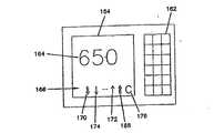
本発明の別の実施形態は、先に説明したセンサ制御ユニットを含む検体監視システムである。この検体監視システムはさらに、少なくとも1つの作用電極と、少なくとも1つの作用電極に結合した少なくとも1つのコンタクト・パッドとを有するセンサを含む。検体監視システムはさらに、センサ制御ユニットからのデータを受信する受信器と、受信器に結合されて検体のレベルを表示するディスプレイとを有する表示ユニットを含む。この表示ユニットは随意的に、例えば送信器、分析器、データ記憶ユニット、監視回路、入力装置、電源、時計、ランプ、小型携帯呼出し機、電話機インタフェース、コンピュータ・インタフェース、アラームまたは警報システム、ラジオ、較正ユニットなど、さまざまな構成要素を含んでもよい。表示ユニットの他の構成要素および随意的要素構成要素および随意的要素については後述する。さらに、検体監視システムまたは検体監視システムの構成要素は、随意的に、薬物または治療プロトコルを決定する機能を有するプロセッサ、および/または薬物送達システムを含む。 Another embodiment of the present invention is an analyte monitoring system that includes the sensor control unit described above. The analyte monitoring system further includes a sensor having at least one working electrode and at least one contact pad coupled to the at least one working electrode. The sample monitoring system further includes a display unit having a receiver for receiving data from the sensor control unit and a display coupled to the receiver for displaying the level of the sample. This display unit optionally includes, for example, a transmitter, an analyzer, a data storage unit, a monitoring circuit, an input device, a power supply, a clock, a lamp, a small handset, a telephone interface, a computer interface, an alarm or alarm system, a radio, Various components may be included such as a calibration unit. Other components and optional components of the display unit and optional components will be described later. Further, the analyte monitoring system or components of the analyte monitoring system optionally include a processor having the capability of determining a drug or treatment protocol, and / or a drug delivery system.
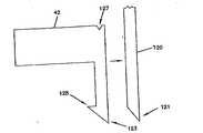
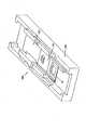
本発明の別の実施形態は、電気化学センサを患者に挿入するための挿入キットである。挿入キットは挿入装置を含む。挿入装置の一部分は、電気化学センサの挿入中にセンサを支持するために適合された鋭く堅い平らな構造を有する。挿入キットはさらに、電気化学センサおよび挿入装置を受け入れるように構成されたポートを有する挿入銃を含む。挿入銃は、挿入装置および電気化学センサを患者の中へ送り込むための駆動機構と、センサを患者の中に残し、挿入装置を取り出すための後退機構とを有する。 Another embodiment of the present invention is an insertion kit for inserting an electrochemical sensor into a patient. The insertion kit includes an insertion device. A portion of the insertion device has a sharp, rigid flat structure adapted to support the sensor during insertion of the electrochemical sensor. The insertion kit further includes an insertion gun having a port configured to receive the electrochemical sensor and the insertion device. The insertion gun has a drive mechanism for feeding the insertion device and electrochemical sensor into the patient, and a retracting mechanism for leaving the sensor in the patient and removing the insertion device.
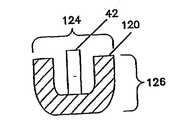
他の実施形態は、電気化学センサを使用する方法である。装着ユニットを患者の皮膚に接着する。装着ユニットのポートと挿入銃の位置を合わせる。挿入銃の中に電気化学センサを配置し、次いで、挿入銃を使用して、電気化学センサを患者の皮膚に挿入する。挿入銃を取り除き、センサ制御ユニットのハウジングを装着ユニットに装着する。ハウジングに配置された複数の導電性コンタクトを、電気化学センサに配置された複数のコンタクト・パッドに結合して、センサを使用する準備を整える。 Another embodiment is a method of using an electrochemical sensor. Glue the mounting unit to the patient's skin. Align the port of the equipped unit with the position of the insertion gun. An electrochemical sensor is placed in the insertion gun, and then the insertion sensor is used to insert the electrochemical sensor into the patient's skin. Remove the insertion gun and mount the sensor control unit housing to the mounting unit. A plurality of conductive contacts disposed on the housing are coupled to a plurality of contact pads disposed on the electrochemical sensor to prepare the sensor for use.
本発明の一実施形態は、埋め込まれた検体応答センサの故障を検出する方法である。検体応答センサを患者に埋め込む。検体応答センサはN個の作用電極および共通の対電極を含む。Nは2以上の整数である。次いで、N個の作用電極のうちの1つおよび共通対電極で生成された信号を取得し、もし共通対電極からの信号が、所定の閾値範囲内で、先の1つの作用電極からの信号のN倍でない場合には、センサは故障していると判定される。 One embodiment of the present invention is a method for detecting a failure of an implanted analyte response sensor. An analyte response sensor is implanted in the patient. The analyte response sensor includes N working electrodes and a common counter electrode. N is an integer of 2 or more. Then, a signal generated by one of the N working electrodes and the common counter electrode is obtained, and if the signal from the common counter electrode is within a predetermined threshold range, the signal from the previous one working electrode is obtained. If it is not N times, the sensor is determined to be faulty.
他の実施形態は、患者に埋め込まれた少なくとも1つの作用電極を有する電気化学センサを較正する方法である。それぞれの作用電極から信号を生成させる。いくつかの条件を試験して、較正が適当かどうかを判定する。第1に、1つ以上のそれぞれの作用電極からの複数の信号は、その差が、第1の閾値よりも小さくなければならない。第2に、1つ以上のそれぞれの作用電極からの複数の信号は所定の範囲に入っていなければならない。第3に、1つ以上のそれぞれの作用電極からの複数の信号の変化速度が、第2の閾値よりも小さくなければならない。患者の体液の較正試料を検定して較正値を見つける。先に記載した条件が満たされる場合、この較正値を、1つ以上のそれぞれの作用電極からの複数の信号のうちの少なくとも1つの信号に関連付ける。 Another embodiment is a method of calibrating an electrochemical sensor having at least one working electrode implanted in a patient. A signal is generated from each working electrode. Several conditions are tested to determine if calibration is appropriate. First, the difference between the multiple signals from one or more respective working electrodes must be less than the first threshold. Second, the multiple signals from one or more respective working electrodes must be within a predetermined range. Third, the rate of change of the plurality of signals from one or more respective working electrodes must be less than the second threshold. A calibration sample of the patient's body fluid is tested to find a calibration value. If the previously described conditions are met, this calibration value is associated with at least one signal of the plurality of signals from one or more respective working electrodes.
他の実施形態は、検体のレベルを監視する方法である。患者の皮膚にセンサを挿入し、センサ制御ユニットを患者の皮膚に取り付ける。センサ制御ユニットの2つ以上の導電性コンタクトをセンサのコンタクト・パッドに結合する。次いで、センサ制御ユニットを使用して、センサによって生成された信号から検体のレベルに関するデータを収集する。収集したデータを表示ユニットに送信し、検体のレベルの指示を表示ユニットに表示する。 Another embodiment is a method for monitoring the level of an analyte. A sensor is inserted into the patient's skin and a sensor control unit is attached to the patient's skin. Two or more conductive contacts of the sensor control unit are coupled to the sensor contact pads. The sensor control unit is then used to collect data regarding the analyte level from the signal generated by the sensor. The collected data is transmitted to the display unit, and an indication of the sample level is displayed on the display unit.
本発明の以上の概要は、本発明の開示したそれぞれの実施形態または全ての実施態様を説明することを意図したものではない。図面および以下の詳細な説明は、これらの実施形態をより具体的に例証する。 The above summary of the present invention is not intended to describe each disclosed embodiment or every implementation of the present invention. The drawings and the following detailed description illustrate these embodiments more specifically.
本発明は、本発明のさまざまな実施形態の以下の詳細な説明を添付の図面とともに検討すると、より完全に理解することができる。
本発明は、さまざまな変形例および代替形態が可能であり、その詳細を図面によって例示し、以下で詳しく説明する。しかし、記載の特定の実施形態に本発明を限定しようとする意図はないことを理解されたい。これとは反対に、その意図は、添付の請求項によって定義される本発明の趣旨および範囲に含まれる全ての修正、等価物および代替物をカバーすることにある。The present invention may be understood more fully upon consideration of the following detailed description of various embodiments of the invention in conjunction with the accompanying drawings.
The invention is susceptible to various modifications and alternative forms, the details of which are illustrated by the drawings and are described in detail below. It should be understood, however, that the intention is not to limit the invention to the particular embodiments described. On the contrary, the intent is to cover all modifications, equivalents, and alternatives falling within the spirit and scope of the invention as defined by the appended claims.
本発明は、埋込み式センサを使用して、流体中のグルコース、乳酸などの検体の濃度を生体内で決定する、検体監視システムに適用可能である。このセンサを例えば、患者の皮下に埋め込んで、患者の間質液中の検体を連続的または定期的に監視することが可能である。続いてこれを使用して、患者の血中のグルコース・レベルを推定することが可能である。本発明によれば、静脈、動脈または流体を含む体内の他の部分に挿入する他の生体内検体センサを製作することが可能である。検体監視システムは一般に、数日から数週、またはそれ以上の期間にわたって検体のレベルを監視するように構成される。 The present invention is applicable to an analyte monitoring system that uses an implantable sensor to determine the concentration of an analyte such as glucose or lactic acid in a fluid in vivo. This sensor can be implanted, for example, under the skin of the patient to monitor the analyte in the patient's interstitial fluid continuously or periodically. This can then be used to estimate the glucose level in the patient's blood. According to the present invention, other in-vivo analyte sensors can be fabricated for insertion into other parts of the body including veins, arteries or fluids. Specimen monitoring systems are generally configured to monitor the level of an analyte over a period of days to weeks or longer.
本願明細書で使用する用語の定義を以下に示す。
「対電極」は、作用電極と対をなす電極である。対電極には、作用電極を流れる電流と大きさが等しく、逆の極性の電流が流れる。本発明の文脈では、用語「対電極」は、参照電極としても機能する対電極(すなわち対電極/参照電極)を含む。Definitions of terms used in the present specification are shown below.
The “counter electrode” is an electrode that makes a pair with the working electrode. The counter electrode has a current of the same polarity as the current flowing through the working electrode, but with the opposite polarity. In the context of the present invention, the term “counter electrode” includes a counter electrode that also functions as a reference electrode (ie, a counter / reference electrode).
「電気化学センサ」は、センサの表面での電気化学的な酸化および還元反応を介して試料中の検体の存在を検出し、かつ/または検体のレベルを測定するように構成された装置である。これらの反応は、試料中の検体の量、濃度またはレベルに相関させることが可能な電気信号に変換される。 An “electrochemical sensor” is a device configured to detect the presence of an analyte in a sample and / or measure the level of an analyte via electrochemical oxidation and reduction reactions on the surface of the sensor. . These reactions are converted into electrical signals that can be correlated to the amount, concentration, or level of analyte in the sample.
「電解」は、電極での直接の、あるいは1種以上の電子移動剤を介した、化合物の電解酸化または電解還元である。
表面に捕捉され、または表面に化学的に結合したときに、化合物が表面に「固定化」されるという。“Electrolysis” is the electrolytic oxidation or reduction of a compound directly at an electrode or via one or more electron transfer agents.
A compound is “immobilized” on a surface when it is captured or chemically bound to the surface.
「非浸出性(non−leachable)」または「非放出性(non−releasable)」化合物、あるいは「非浸出的に配置された(non−leachably disposed)」化合物は、センサを使用している間(例えばセンサが患者に埋め込まれている間、またはセンサが試料を測定している間)、作用電極の作用表面からさほど拡散しないような方法でセンサの表面に付着させた化合物と定義される。 “Non-leaachable” or “non-releasable” compounds or “non-leaachable dissipated” compounds may be used while using the sensor ( It is defined as a compound deposited on the surface of the sensor in such a way that it does not diffuse significantly from the working surface of the working electrode (for example, while the sensor is implanted in a patient or while the sensor is measuring a sample).
例えばある成分が、センサの構成要素に共有結合、イオン結合、または配位結合し、かつ/または移動を妨げるポリマー・マトリックスまたは膜あるいはゾル−ゲル・マトリックスまたは膜に捕捉されたときに、その成分はセンサの内部に「固定化」されたという。 For example, when a component is trapped in a polymer matrix or membrane or sol-gel matrix or membrane that is covalently, ionic, or coordinated to a sensor component and / or prevents migration Is said to be “fixed” inside the sensor.
「電子移動剤」は、直接に、または他の電子移動剤と協同して、検体と作用電極の間で電子を運ぶ化合物である。電子移動剤の一例が酸化還元媒介物質である。
「作用電極」は、電子移動剤の媒介の有無にかかわらず、そこで検体(またはそのレベルが検体のレベルに依存する第2の化合物)が電解酸化または電解還元される電極である。An “electron transfer agent” is a compound that carries electrons between an analyte and a working electrode, either directly or in cooperation with other electron transfer agents. An example of an electron transfer agent is a redox mediator.
A “working electrode” is an electrode where an analyte (or a second compound whose level depends on the level of the analyte) is electrolytically oxidized or reduced, regardless of the presence or absence of an electron transfer agent.
「作用表面」は、電子移動剤で覆われた、または電子移動剤に接近可能な作用電極の部分であって、検体を含む流体に暴露されるように構成された部分である。
「検出層」は、検体の電解を促進する成分を含んだセンサの構成要素である。検出層は、電子移動剤、検体の反応を触媒して電極での応答を生み出す触媒、これらの組合せなどの成分を含んでもよい。センサの一部の実施形態では、検出層が、作用電極の近くに、または作用電極の表面に非浸出的に配置された層である。The “working surface” is the portion of the working electrode that is covered with or accessible to the electron transfer agent that is configured to be exposed to the fluid containing the analyte.
The “detection layer” is a component of the sensor including a component that promotes electrolysis of the specimen. The detection layer may include components such as an electron transfer agent, a catalyst that catalyzes the reaction of the analyte to produce a response at the electrode, and combinations thereof. In some embodiments of the sensor, the detection layer is a layer disposed non-leaching near the working electrode or on the surface of the working electrode.
「非腐食性」導電材料には炭素、導電性ポリマーなどの非金属材料が含まれる。
検体センサ・システム
本発明の検体監視システムはさまざまな条件の下で利用することが可能である。検体監視システムで使用されるセンサおよび他のユニットの具体的な構成は例えば、意図する検体監視システムの用途、および検体監視システムが動作する条件によって決まる。検体監視システムの一実施形態は、患者または使用者に埋め込むように構成されたセンサを含む。センサの埋込みは例えば、血液中の検体のレベルを直接に検査するために、動脈または静脈系に実施することができる。あるいは、間質液中の検体のレベルを決定するために、センサを間質組織に埋め込むことができる。この間質液中の検体のレベルを、血液または他の流体中の検体のレベルに相関させ、かつ/または血液または他の流体中の検体のレベルに変換することができる。埋込み部位および埋込みの深さが、センサの具体的な形状、構成要素および構成に影響する場合がある。場合によっては、センサの埋込みの深さを制限するために皮下埋込みが好ましい場合がある。他の流体中の検体のレベルを決定するために、センサを体の他の領域に埋め込むこともできる。本発明の検体監視システムで使用するのに適したセンサの例が、本願明細書に援用する米国特許出願番号09/034,372に記載されている。“Non-corrosive” conductive materials include non-metallic materials such as carbon and conductive polymers.
Sample Sensor System The sample monitoring system of the present invention can be used under various conditions. The specific configuration of the sensors and other units used in the sample monitoring system depends, for example, on the intended use of the sample monitoring system and the conditions under which the sample monitoring system operates. One embodiment of an analyte monitoring system includes a sensor configured to be implanted in a patient or user. Sensor implantation can be performed, for example, in the arterial or venous system to directly examine the level of an analyte in the blood. Alternatively, a sensor can be embedded in the interstitial tissue to determine the level of the analyte in the interstitial fluid. The level of the analyte in the interstitial fluid can be correlated to the level of the analyte in blood or other fluid and / or converted to the level of the analyte in blood or other fluid. The implantation site and the depth of implantation may affect the specific shape, components and configuration of the sensor. In some cases, subcutaneous implantation may be preferred to limit the depth of sensor implantation. Sensors can also be implanted in other areas of the body to determine the level of analyte in other fluids. An example of a sensor suitable for use in the analyte monitoring system of the present invention is described in US patent application Ser. No. 09 / 034,372, incorporated herein by reference.
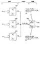
埋込み式センサ42、具体的には皮下埋込み式センサとともに使用される検体監視システム40の一実施形態を図1のブロック図に示す。検体監視システム40は少なくともその一部分を患者(例えば皮下、静脈または動脈)に埋め込むように構成されたセンサ42と、センサ制御ユニット44とを含む。センサ42は、患者の皮膚に一般に取り付けられるセンサ制御ユニット44に結合される。センサ制御ユニット44はセンサ42を操作する。操作には例えば、センサ42の電極間に電圧を供給し、センサ42からの信号を収集することが含まれる。センサ制御ユニット44はセンサ42からの信号を評価し、かつ/または、随意的な1台以上の受信/表示ユニット46,48に評価のため信号を送信することができる。センサ制御ユニット44および/または受信/表示ユニット46,48は現在の検体のレベルを表示し、または他の方法で知らせることができる。さらに、センサ制御ユニット44および/または受信/表示ユニット46,48は、例えば可聴または視覚警報、あるいは他の感覚刺激警報によって、検体のレベルが閾値に達したこと、または閾値に近いことを患者に指示することができる。一部の実施形態では、センサの一方の電極または随意的な温度プローブを通して電気ショックを警告として患者に送達することが可能である。例えば、グルコースを監視する場合には、警報を使用して、低血糖または高血糖グルコース・レベルにあること、および/あるいは低血糖または高血糖になりかかっていることを患者に警報することができる。 One embodiment of an
センサ
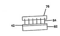
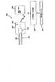
図2に示すように、センサ42は、基板50の表面に形成された少なくとも1つの作用電極58を含む。センサ42はさらに、少なくとも1つの対電極60(または対電極/参照電極)、および/または少なくとも1つの参照電極62(図8参照)を有してもよい。対電極60および/または参照電極62は基板50の表面に形成することができ、あるいは別個のユニットとすることができる。例えば、対電極および/または参照電極を、やはり患者に埋め込まれる第2の基板の表面に形成することができ、あるいは埋込み可能センサの一部の実施形態では、少なくとも1つの作用電極を患者に埋め込み、対電極および/または参照電極は患者の皮膚の表面に配置することができる。皮膚表面の対電極および/または参照電極を埋込み式作用電極とともに使用することは、本願明細書に援用する米国特許第5593852号に記載されている。Sensor As shown in FIG. 2, the
少なくとも1つの作用電極58は、基板50の表面に配置された導電性トレース52を使用して形成される。対電極60および/または参照電極62、ならびに温度プローブ66(図8参照)などのセンサ42の随意的な部分も、基板50の表面に配置された導電性トレース52を使用して形成することができる。これらの導電性トレース52は、基板50の平らな表面に凹みを形成するか、あるいは、例えば基板50にエンボス加工を施し、基板50をくぼませるか、または他の方法で基板50に凹みを作り出すことによって形成された溝54の中に形成することができる。 At least one working
試料流体中の検体の電気化学検出および検体のレベルの決定を容易にするために、特に、裸電極の表面で所望の速度で、かつ/または所望の特異性で検体が電解されない場合に、検出層64(図3Aおよび3B参照)がしばしば、少なくとも1つの作用電極58の近くに、または作用電極58の表面に形成される。検体と作用電極58の間で電子を直接にまたは間接的に移動させるために、検出層64は電子移動剤を含んでもよい。検出層64はさらに、検体の反応を触媒する触媒を含んでもよい。検出層の成分は、作用電極58に近接し、または作用電極58と接触した流体またはゲルとすることができる。あるいは、検出層64の成分を、作用電極58の近くに、または作用電極58の表面に配置されたポリマーまたはゾル−ゲル・マトリックスの中に配置することができる。検出層64の成分は、センサ42の中に非浸出性に配置されていることが好ましい。センサ42の成分がセンサ42の内部に固定化されていることがより好ましい。 Detection to facilitate the electrochemical detection of analyte in the sample fluid and determination of analyte level, especially when the analyte is not electrolyzed at the desired rate and / or with the desired specificity on the surface of the bare electrode Layer 64 (see FIGS. 3A and 3B) is often formed near or on the surface of at least one working
後に説明するが、電極58,60,62および検出層64の他にセンサ42はさらに、温度プローブ66(図6および8参照)、質量輸送制限層74(図9参照)、生体適合層75(図9参照)、および/または随意的に他の構成要素を有してもよい。これらの個別要素はそれぞれ、後に論じるように、センサ42の機能を強化し、かつ/またはセンサ42に由来する。 As will be described later, in addition to the
基板
基板50は、例えばポリマーまたはプラスチック材料、およびセラミック材料を含む、さまざまな非電導性材料を使用して形成され得る。特定のセンサ42に適した材料は、少なくとも部分的には、センサ42の所望の用途および材料の特性に基づいて決定され得る。Substrate The
一部の実施形態では基板は可撓性を有する。例えば、センサ42が患者に埋め込むように構成されている場合には、センサ42の埋込みおよび/または着用によって引き起こされる患者の痛みを和らげ、組織への損傷を低減するために、センサ42を可撓にすることができる(ただし埋込み式センサに対して堅いセンサを使用することもできる)。可撓性を有する基板50はしばしば患者の快適性を高め、より幅広い活動を可能にする。可撓性を有する基板50に適した材料には例えば、非電導性プラスチックまたはポリマー材料および他の可撓性を有しかつ変形可能な非電導性材料が含まれる。有用なプラスチックまたはポリマー材料の例には、ポリカーボネート、ポリエステル(例えばMylar(商標)およびポリエチレンテレフタレート(PET))、ポリ塩化ビニル(PVC)、ポリウレタン、ポリエーテル、ポリアミド、ポリイミドなどの熱可塑性プラスチック、またはこれらの熱可塑性プラスチックの共重合体、例えばPETG(グリコール修飾ポリエチレンテレフタレート)が含まれる。 In some embodiments, the substrate is flexible. For example, if the
他の実施形態では、曲げまたは破壊に対する構造上の支持を与えるために、センサ42が比較的に堅い基板50を使用して作られる。基板50として使用することができる堅い材料の例には、酸化アルミニウム、二酸化ケイ素などの低導電性セラミックが含まれる。堅い基板を有する埋込み可能センサ42の1つの利点は、センサ42の先端および/または縁を鋭くして、追加の挿入装置なしでもセンサ42を埋め込みやすくすることができる点である。 In other embodiments,
多くのセンサ42および多くのセンサ応用例で、堅いセンサおよび可撓性を有するセンサの両方が十分に動作することを理解されたい。さらに、例えば基板50の組成および/または厚さを変更することによって、センサ42の可撓性を連続的に制御し、変更することができる。 It should be understood that for
可撓性に関する考慮事項に加えて、多くの場合に、埋込み可能センサ42が毒性のない基板50を有することが望ましい。基板50は、1つ以上の適当な政府機関または民間団体によって生体内使用が認められていることが好ましい。 In addition to flexibility considerations, it is often desirable for the
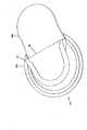
センサ42は、埋込み可能センサ42の挿入を容易にする、図12に示すような随意的な機構を有してもよい。例えば、挿入を容易にするために、センサ42の先端123を尖らせることができる。さらに、センサ42は、センサ42が動作している間、患者の組織内にセンサ42を固定するのを助けるかえし125を有してもよい。しかし、かえし125は一般に小さく、そのため、交換のためにセンサ42を取り外すときに皮下組織を傷つけることはほとんどない。 The
少なくとも一部の実施形態では基板50が、センサ42の全長に沿って均一な寸法を有するが、他の実施形態では、図2に示すように基板50が、幅53および55が異なる遠位端67および近位端65を有する。これらの実施形態では、基板50の遠位端67が相対的に狭い幅53を有することができる。皮下組織または患者の体内の他の部分に埋込み式センサ42では、基板50の遠位端67の幅53を狭くすることによって、センサ42の埋込みを容易にすることができる。多くの場合、センサ42の幅が狭いほど、センサの埋込み中およびその後に患者が感じる痛みは小さい。 In at least some embodiments, the
患者の通常の活動中に検体を連続的にまたは定期的に監視するように設計された、皮下埋込み式センサ42では、患者に埋め込むセンサ42の遠位端67の幅53が2mm以下、好ましくは1mm以下、より好ましくは0.5mm以下である。センサ42が幅の異なる領域を持たない場合、センサ42の全幅は一般に、例えば、2mm、1.5mm、1mm、0.5mm、0.25mm、またはそれ以下である。しかし、これよりも幅の広いセンサ、または幅の狭いセンサを使用することもできる。具体的には、静脈または動脈に挿入する目的に、あるいは患者の運動が制限されているときに、例えば患者がベッド上または病院内に拘束されているときに、より幅の広い埋込み可能センサを使用してもよい。 In a subcutaneously
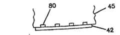
図2に戻る。電極のコンタクト・パッド49と制御ユニット上のコンタクトとの間の接続を容易にするために、センサ42の近位端65の幅55を遠位端67の幅よりも広くすることができる。センサ42の近位端の幅が広いほど、コンタクト・パッド49を大きくすることが可能である。こうすることによって、制御ユニット(例えば図1のセンサ制御ユニット44)のコンタクトにセンサ42を適正に接続するのに要する精密さを減らすことができる。しかし、患者の利便性および快適性のため、ならびに/または所望のサイズの検体監視装置を取り付けるため、センサ42が小さくなるようにセンサ42の最大幅を限定することができる。例えば、図1に示したセンサ42などの皮下埋込み式センサ42の近位端65の幅55を、0.5mmから15mm、好ましくは1mmから10mm、より好ましくは3mmから7mmにすることができる。しかし、これよりも幅の広いセンサまたは幅の狭いセンサを、この生体内応用および他の生体内応用で使用することができる。 Returning to FIG. To facilitate the connection between the
基板50の厚さは、後に論じるように、基板材料の機械的特性(例えば材料の強度、引張応力および/または可撓性)、使用時に生じる基板50の応力などのセンサ42の所望の用途、および基板50に形成された溝またはくぼみの深さによって決定され得る。一般に、患者が通常の活動に従事している間に検体のレベルを連続的にまたは定期的に監視する皮下埋込み式センサ42の基板50の厚さは、50〜500μm、好ましくは100〜300μmである。しかし、特に他のタイプの生体内センサ42では、これよりも厚い基板および薄い基板50を使用してもよい。 The thickness of the
センサ42の長さは、さまざまな因子に基づいて広範な値をとることができる。埋込み式センサ42の長さに影響を与える因子には例えば、患者への埋込み深さ、および小さく可撓性を有するセンサ42を操り、センサ42とセンサ制御ユニット44とを接続する患者の能力が含まれる。図1に示した検体監視装置用の皮下埋込み式センサ42の長さは0.3〜5cmとすることができる。ただし、これよりも長いセンサまたは短いセンサを使用することもできる。幅の狭い部分と広い部分とを有するセンサ42の場合、センサ42の幅の狭い部分(例えば患者の皮下に挿入される部分)の長さは一般に約0.25〜2cmである。ただし、これよりも長い部分および短い部分を使用することもできる。この幅の狭い部分全体または一部分だけを、患者の皮下に埋め込むことができる。他の埋込み式センサ42の長さは、少なくとも1つには、センサ42を埋め込みまたは挿入する患者の部分によって異なる。 The length of the
導電性トレース
作用電極58の構築に使用される少なくとも1つの導電性トレース52が基板の表面に形成される。基板50の表面にはさらに、電極(例えば追加の作用電極、対電極、対電極/参照電極、および/または参照電極)として、および温度プローブなどの他の構成要素として使用する別の導電性トレース52を形成され得る。導電性トレース52は、図2に示すように、センサ50の長さ57のほぼ全体に沿って延びてもよい。ただしこれは必須ではない。導電性トレース52の配置は例えば、検体監視システムの具体的な構成(例えばセンサ42に対する制御ユニットのコンタクトおよび/または試料室の相対配置)によって決まる。埋込み式センサ、特に皮下埋込み式センサでは、埋め込まれなければならないセンサの量をできるだけ小さくするために、導電性トレースが一般にセンサ42の先端近くまで延びる。Conductive traces At least one
導電性トレース52は、例えばフォトリソグラフィ、スクリーン印刷、あるいはインパクトまたはノンインパクト方式の他の印刷技法を含むさまざまな技法によって、基板50の表面に形成され得る。導電性トレース52は、有機(例えばポリマーまたはプラスチック)基板50中の導電性トレース52をレーザを使用して炭化することによっても形成され得る。センサ42を形成する例示的ないくつかの方法の説明が、本願明細書に援用する米国特許出願番号09/034,422に記載されている。
基板50の表面に導電性トレース52を配置する他の方法は、図3Aに示すように、基板50の1つ以上の表面に凹んだ溝54を形成し、続いてこれらの凹んだ溝54に導電材料56を充てんすることを含む。凹んだ溝54は、基板50の表面をくぼませ、表面にエンボス加工を施すか、または他の方法で基板50の表面に凹みを作り出すことによって形成され得る。基板の表面に溝および電極を形成する例示的な方法が米国特許出願番号09/034,422に記載されている。溝の深さは一般に基板50の厚さに関係する。一実施形態においては、溝の深さが約12.5〜75μm(0.5〜3ミル)、好ましくは約25.4〜50.8μm(1〜2ミル)である。 Another method of placing the conductive traces 52 on the surface of the
導電性トレースは一般に、炭素(例えば黒鉛)、導電性ポリマー、金属または合金(例えば金または金合金)、金属化合物(例えば二酸化ルテニウムまたは二酸化チタン)などの導電材料56を使用して形成される。炭素、導電性ポリマー、金属、合金または金属化合物のフィルムの形成はよく知られており、これには例えば、化学蒸着(CVD)、物理蒸着、スパッタリング、反応性スパッタリング、印刷、コーティングおよび塗装が含まれる。溝54に充てんする導電材料56は多くの場合、導電性インク、ペーストなどの前駆材料を使用して形成される。これらの実施形態では、コーティング、塗装などの方法を使用して基板50の表面に導電材料56を付着させ、またはコーティング・ブレードなどの塗広げ具を使用して材料を塗布する。溝54と溝54の間の過剰の導電材料は、例えば基板表面に沿ってブレードを走らせることによって取り除く。 The conductive traces are generally formed using a
一実施形態においては、導電材料56が、例えばアーコン・インコーポレーテッド社(Ercon,Inc)(米マサチューセッツ州ウェアラム(Wareham))、メテック・インコーポレーテッド社(Metech,Inc)(米ペンシルバニア州エルバーソン(Elverson))、イー・アイ・デュポン・ド・ヌムール・アンド・カンパニー社(E.I.du Pont de Nemours and Co.)(米デラウェア州ウィルミントン(Wilmington))、エムカ−リメックス・プロダクツ社(Emca−Remex Products)(米ペンシルバニア州モンゴメリービル(Montgomeryville))、またはエムシーエー・サービシズ社(MCA Services)(英国メルバーン(Melbourn))から入手可能な導電性インクなどの前駆材料の一部分である。導電性インクは一般に、炭素、金属、合金または金属化合物の粒子と溶剤または分散剤とを含む半液体またはペーストとして塗布される。基板50に(例えば溝54の中に)導電性インクを塗布した後に、溶剤または分散剤は蒸発して、導電材料56の固体の塊が残る。 In one embodiment, the
炭素、金属、合金または金属化合物の粒子に加えて、導電性インクはさらに結合剤を含んでもよい。随意的に結合剤を硬化させて、溝54の内部および/または基板50の表面の導電材料56をさらに結合させることができる。結合剤を硬化させると導電材料56の導電率が高まる。ただしこれは一般に必須ではない。と言うのも、導電性トレース52の導電材料56によって運ばれる電流は多くの場合に比較的に小さい(通常は1μA未満、しばしば100nA未満)からである。一般的な結合剤には例えば、ポリウレタン樹脂、セルロース誘導体、エラストマーおよび高フッ素化ポリマーが含まれる。エラストマーの例には、シリコーン、重合ジエン、およびアクリロニトリル−ブタジエン−スチレン(ABS)樹脂がある。フッ素化ポリマー結合剤の一例がTeflon(登録商標)(デュポン社、米デラウェア州ウィルミントン)である。これらの結合剤は、例えば熱、または紫外(UV)光を含む光を使用して硬化させる。適当な硬化方法は一般に、使用する具体的な結合剤によって異なる。 In addition to the carbon, metal, alloy or metal compound particles, the conductive ink may further comprise a binder. Optionally, the binder can be cured to further bond the
多くの場合、導電材料56の液体または半液体前駆材料(例えば導電性インク)を溝54の中に付着させるときには、前駆材料が溝54を埋める。しかし、溶剤または分散剤が蒸発すると、残った導電材料56の体積が減少し、その結果、導電材料56が引き続き溝54を埋めることもあれば、埋めないこともある。好ましい導電材料56は、体積が減少すると基板50から剥がれることなく、溝54の中で高さを減らす。これらの導電材料56は一般に基板50によく接着し、したがって溶剤または分散剤の蒸発中に基板50から剥がれない。他の適当な導電材料56は、基板50の少なくとも一部分に接着し、かつ/または結合剤などの、導電材料56を基板50に接着する他の添加剤を含む。溝54の中の導電材料56は非浸出性材料であることが好ましく、基板50上に固定化されていることがより好ましい。一部の実施形態では導電材料56を、溶剤または分散剤の除去を間に挟んで液体または半液体前駆材料を数回にわたって塗布することによって形成する。 In many cases, when a liquid or semi-liquid precursor material (eg, conductive ink) of
他の実施形態ではレーザを使用して溝54を形成する。レーザは、ポリマーまたはプラスチック材料を炭化する。この工程で形成された炭素を導電材料56として使用する。導電性炭素インクなどの追加の導電材料56を使用して、レーザによって形成された炭素を補うことができる。 In other embodiments, the
他の実施形態では、パッド印刷技法によって導電性トレース52を形成する。例えば、導電材料のフィルムを連続フィルムとして、または担体フィルムの表面に付着させたコーティング層として形成する。この導電材料のフィルムを印刷ヘッドと基板50の間に置く。印刷ヘッドを使用して基板50の表面にパターンを、導電性トレース52の所望のパターンに従って形成する。圧力および/または熱によって導電材料を、導電材料のフィルムから基板50に転写する。この技法はしばしば基板50の中に溝(例えば印刷ヘッドによって生じる凹み)を生み出す。あるいは、実質的な凹みを形成することなく基板50の表面に導電材料を付着させる。 In other embodiments, conductive traces 52 are formed by pad printing techniques. For example, the conductive material film is formed as a continuous film or as a coating layer attached to the surface of the carrier film. A film of this conductive material is placed between the print head and the
他の実施形態では、ノンインパクト方式の印刷技法によって導電性トレース52を形成する。このような技法には電子写真法およびマグネトグラフィが含まれる。これらの工程では、ドラムの表面に導電性トレース52の像を、電気的にまたは磁気的に形成する。電気的に像を形成するためにはレーザまたはLEDを使用してもよい。磁気的に像を形成するためには磁気記録ヘッドを使用してもよい。次いでトナー材料(例えば導電性インクなどの導電材料)を、像のとおりにドラムの部分に引き寄せる。次いでドラムと基板の間の接触によってトナー材料を基板に塗布する。例えば、ドラム上で基板を転がすことができる。次いでトナー材料を乾かし、かつ/またはトナー材料の中の結合剤を硬化させて、トナー材料を基板に接着してもよい。 In other embodiments, the conductive traces 52 are formed by non-impact printing techniques. Such techniques include electrophotography and magnetography. In these steps, an image of the
ノンインパクト方式の別の印刷技法に、導電材料の小滴を基板の表面に所望のパターンで噴射することがある。この技法の例にはインクジェット印刷および圧電ジェット印刷が含まれる。プリンタに像が送られ、次いでプリンタが、導電材料(例えば導電性インク)をパターンに従って噴射する。プリンタは、導電材料の連続流を噴射しても、所望の点に導電材料を離散的に噴射してもよい。 Another non-impact printing technique is to eject droplets of conductive material in the desired pattern onto the surface of the substrate. Examples of this technique include ink jet printing and piezoelectric jet printing. The image is sent to the printer, which then ejects a conductive material (eg, conductive ink) according to the pattern. The printer may jet a continuous flow of conductive material or may discretely jet the conductive material to a desired point.
導電性トレースを形成するノンインパクト方式の別の印刷実施形態は、イオノグラフィ工程を備える。この工程では、光重合可能なアクリル樹脂(例えばキュービタル社(Cubital)(独バート・クロイツナハ(Bad Kreuznach))のSolimer7501)などの硬化可能な液体前駆材料を基板50の表面に付着させる。次いで、導電性トレース52のポジまたはネガ像を有するフォトマスクを使用して、液体前駆材料を硬化させる。フォトマスクを通して光(例えば可視または紫外光)を導いて、液体前駆材料を硬化させ、基板の上にフォトマスクの像どおりの固体層を形成する。硬化していない液体前駆材料を除去し、固体層中に溝54を残す。次いで、これらの溝54に導電材料56を充てんして導電性トレース52を形成する。 Another non-impact printing embodiment for forming conductive traces comprises an ionographic process. In this step, a curable liquid precursor material such as a photopolymerizable acrylic resin (eg, Solider 7501 from Cubital (Bad Kreuznach)) is deposited on the surface of the
導電性トレース52(および使用する場合には溝54)は、先に説明した方法によって、比較的に狭い幅、例えば250μm、150μm、100μm、75μm、50μm、25μmまたはこれ未満を含む25〜250μmの幅に形成することが可能である。基板50の同じ側に2つ以上の導電性トレース52を有する実施形態では、導電性トレース52間の導通を防ぐために、導電性トレース52を十分な距離をとって分離する。2つの導電性トレースの縁と縁の間の距離は、25〜250μmであることが好ましく、例えば150μm、100μm、75μm、50μm、またはこれ未満とすることができる。基板50上の導電性トレース52の密集度は、約150〜700μm/トレースであることが好ましく、667μm/トレース以下、333μm/トレース以下、または167μm/トレース以下とすることができる。 Conductive trace 52 (and
作用電極58および対電極60(別に参照電極を使用する場合)は多くの場合に、炭素などの導電材料56を使用して作られる。適切な炭素導電性インクは、アーコン・インコーポレーテッド社(Ercon,Inc)(米マサチューセッツ州ウェアラム(Wareham))、メテック・インコーポレーテッド社(Metech,Inc)(米ペンシルバニア州エルバーソン(Elverson))、イー・アイ・デュポン・ド・ヌムール・アンド・カンパニー社(E.I.du Pont de Nemours and Co.)(米デラウェア州ウィルミントン(Wilmington))、エムカ−リメックス・プロダクツ社(Emca−Remex Products)(米ペンシルバニア州モンゴメリービル(Montgomeryville))、またはエムシーエー・サービシズ社(MCA Services)(英国メルバーン(Melbourn))から入手可能である。一般に、作用電極58の作用表面51は、検体を含む流体と接触する(例えば患者に埋め込まれる)導電性トレース52の少なくとも一部分である。 The working
参照電極62および/または対電極/参照電極は一般に、適切な標準物質、例えば銀/塩化銀、または導電材料に結合した非浸出性な酸化還元対、例えば炭素に結合した酸化還元対である、導電材料56を使用して形成される。適切な銀/塩化銀導電性インクは、アーコン・インコーポレーテッド社(Ercon,Inc)(米マサチューセッツ州ウェアラム(Wareham))、メテック・インコーポレーテッド社(Metech,Inc)(米ペンシルバニア州エルバーソン(Elverson))、イー・アイ・デュポン・ド・ヌムール・アンド・カンパニー社(E.I.du Pont de Nemours and Co.)(米デラウェア州ウィルミントン(Wilmington))、エムカ−リメックス・プロダクツ社(Emca−Remex Products)(米ペンシルバニア州モンゴメリービル(Montgomeryville))、またはエムシーエー・サービシズ社(MCA Services)(英国メルバーン(Melbourn))から入手可能である。銀/塩化銀電極は、試料または体液の成分、このケースではCl−と金属電極との反応を含むタイプの参照電極の例である。The
参照電極の導電材料に結合させるのに適した酸化還元対には、例えば、酸化還元ポリマー(例えば複数の酸化還元中心を有するポリマー)がある。誤った電位が測定されないように、参照電極の表面は非腐食性であることが好ましい。好ましい導電材料には、金、パラジウムなどの低腐食性金属が含まれる。最も好ましいのは、炭素、導電性ポリマーなどの非金属導体を含む非腐食性材料である。酸化還元ポリマーは、導電性トレース52の炭素表面などの参照電極の導電材料に吸着させ、または共有結合させることが可能である。非ポリマー酸化還元対も同様に炭素または金表面に結合させることが可能である。 Suitable redox couples for binding to the conductive material of the reference electrode include, for example, redox polymers (eg, polymers having multiple redox centers). The surface of the reference electrode is preferably non-corrosive so that no false potential is measured. Preferred conductive materials include low corrosive metals such as gold and palladium. Most preferred are non-corrosive materials including non-metallic conductors such as carbon and conductive polymers. The redox polymer can be adsorbed or covalently bonded to a conductive material of a reference electrode, such as the carbon surface of the
さまざまな方法を使用して、電極の表面に酸化還元ポリマーを固定化することができる。1つの方法が吸着固定化である。この方法は特に、比較的に大きな分子量を有する酸化還元ポリマーに対して有用である。ポリマーの分子量は、例えば架橋によって増大させることができる。 Various methods can be used to immobilize the redox polymer on the surface of the electrode. One method is adsorption immobilization. This method is particularly useful for redox polymers having a relatively large molecular weight. The molecular weight of the polymer can be increased, for example, by crosslinking.
酸化還元ポリマーを固定化する別の方法は、電極の表面を官能基化し、次いで、電極表面の官能基に酸化還元ポリマーを、多くの場合に共有結合によって化学的に結合させることを含む。このタイプの固定化の一例は、ポリ(4−ビニルピリジン)から出発する。このポリマーのピリジン環は、部分的に、還元可能/酸化可能種と[Os(bpy)2Cl]+/2+などの錯体を形成している(bpyは2,2’−ビピリジンである)。ピリジン環の一部は、2−ブロモエチルアミンとの反応によって四級化されている。次いで、例えばポリエチレングリコールジグリシジルエーテルなどのジエポキシドを使用して、このポリマーを架橋させる。Another method of immobilizing the redox polymer involves functionalizing the surface of the electrode and then chemically bonding the redox polymer to the functional group on the electrode surface, often by a covalent bond. An example of this type of immobilization starts from poly (4-vinylpyridine). The pyridine ring of this polymer partially forms a complex such as [Os (bpy)2 Cl]+ / 2 + with a reducible / oxidizable species (bpy is 2,2′-bipyridine). Part of the pyridine ring has been quaternized by reaction with 2-bromoethylamine. The polymer is then crosslinked using, for example, a diepoxide such as polyethylene glycol diglycidyl ether.
炭素表面は、酸化還元種またはポリマーを付加させるために、例えばジアゾニウム塩の電解還元によって修飾することが可能である。一例として、p−アミノ安息香酸のジアゾ化後に形成されるジアゾニウム塩の還元は、炭素表面を、フェニルカルボン酸官能基で修飾する。次いで、塩酸1−エチル−3−(3−ジメチルアミノプロピル)−カルボジイミドなどのカルボジイミドによって、これらの官能基を活性化させることが可能である。活性化させた官能基を次いで、先に説明した四級化されたオスミウム含有酸化還元ポリマー、2−アミノエチルフェロセンなどのアミン官能基化酸化還元対と結合させて、酸化還元対を形成する。 The carbon surface can be modified, for example, by electroreduction of a diazonium salt to add a redox species or polymer. As an example, reduction of the diazonium salt formed after diazotization of p-aminobenzoic acid modifies the carbon surface with a phenylcarboxylic acid functional group. These functional groups can then be activated by carbodiimides such as 1-ethyl-3- (3-dimethylaminopropyl) -carbodiimide hydrochloride. The activated functional group is then combined with an amine functionalized redox couple such as the quaternized osmium-containing redox polymer described above, 2-aminoethylferrocene, to form a redox couple.
同様に、シスタミンなどのアミンによって金を官能基化することが可能である。[Os(bpy)2(ピリジン−4−カルボキシラート)Cl]0/+などの酸化還元対を、塩酸1−エチル−3−(3−ジメチルアミノプロピル)−カルボジイミドによって活性化させて、金に結合したアミンと反応してアミドを形成する反応性のO−アシルイソ尿素を形成する。Similarly, gold can be functionalized with amines such as cystamine. A redoxcouple such as [Os (bpy)2 (pyridine-4-carboxylate) Cl]0 / + is activated by 1-ethyl-3- (3-dimethylaminopropyl) -carbodiimide hydrochloride to produce gold. Reactive O-acylisoureas that react with bound amines to form amides are formed.
一実施形態においては、導電性トレース52を電極またはプローブ・リードとして使用する他に、基板50上の2つ以上の導電性トレース52を使用して、例えば検体のレベルが閾値を超えたときに弱い電気ショックを患者に与える。このショックを例えば、適切な検体のレベルを回復させるための行動を開始するよう患者に警告する警告または警報として使用することができる。 In one embodiment, in addition to using
弱い電気ショックは、導電リードによって接続されていない2つの導電性トレース52間に電位をかけることによって生み出す。例えば、電極58,60,62のうちの2つ、または1つの電極58,60,62と温度プローブ66を使用して、弱いショックを与えることができる。作用電極58および参照電極62はこの目的には使用しないことが好ましい。これは、こうすることによって、この特定の電極の表面、またはこの電極の近くに存在する化学的構成要素(例えば作用電極の検出層または参照電極の酸化還元対)にある種の損傷が引き起こされる可能性があるためである。 A weak electrical shock is created by applying a potential between two
弱いショックを生み出すのに使用される電流は一般に0.1〜1mAである。これよりも大きな電流または小さな電流を使用することもできるが、患者に危害を与えないよう注意しなければならない。導電性トレース間の電位は一般に1〜10ボルトである。しかし、例えば導電性トレース52の抵抗、導電性トレース52間の距離および所望の電流量に応じて、これよりも高い電圧または低い電圧を使用してもよい。作用電極58(および/または使用する場合には温度プローブ66)と弱いショックを与える導電性トレース52との間の不必要な導通によって引き起こされる構成要素への危害を防ぐために、弱いショックを送達するときには、作用電極58の電位および温度プローブ66の両端間の電位を除去することができる。 The current used to create a weak shock is typically 0.1-1 mA. Larger or smaller currents can be used, but care must be taken not to harm the patient. The potential between the conductive traces is typically 1-10 volts. However, higher or lower voltages may be used, depending on, for example, the resistance of the conductive traces 52, the distance between the
コンタクト・パッド
一般に、導電性トレース52はそれぞれコンタクト・パッド49を含む。コンタクト・パッド49は単純に、コンタクト・パッド49が制御ユニット(例えば図1のセンサ制御ユニット44)の導電性コンタクトと接触することを除いて、トレース52の残りの部分から区別できない導電性トレース52の一部分とすることができる。しかし、より一般的にはコンタクト・パッド49は、制御ユニットのコンタクトとの接続を容易にするためにトレース52の他の領域よりも大きな幅を有する導電性トレース52の領域である。導電性トレース52の幅に比べてコンタクト・パッド49を相対的に大きくすることによって、コンタクト・パッド49と制御ユニットのコンタクトとの間の正確な位置合せの必要性が、小さなコンタクト・パッドで求められるほどには重要でなくなる。Contact Pads Generally, the conductive traces 52 each include a
コンタクト・パッド49は一般に、導電性トレース52の導電材料56と同じ材料を使用して製作することができる。ただしこれは必須ではない。金属、合金および金属化合物を使用してコンタクト・パッド49を形成することができるが、一部の実施形態では、炭素または導電性ポリマーなどの他の非金属材料からコンタクト・パッド49を製作することが望ましい。金属または合金コンタクト・パッドとは対照的に、炭素コンタクト・パッドおよび他の非金属コンタクト・パッドは、コンタクト・パッド49が湿った環境、濡れた環境、または湿気の多い環境にある場合に簡単には腐食しない。金属および合金はこれらの条件下で腐食する可能性があり、コンタクト・パッド49と制御ユニットのコンタクトが異なる金属または合金を使用して作られている場合には特にそうである。しかし、炭素および非金属コンタクト・パッド49は、たとえ制御装置のコンタクトが金属または合金であっても、それほど腐食しない。
本発明の一実施形態は、コンタクト・パッド49を有するセンサ42、および導電性コンタクト(図示せず)を有する制御ユニット44を有する。センサ42の動作中は、コンタクト・パッド49と導電性コンタクトが互いに接触している。この実施形態では、コンタクト・パッド49と導電性コンタクトのうちのいずれかが、非腐食性の導電性材料を使用して製作される。このような材料には例えば炭素および導電性ポリマーが含まれる。好ましい非腐食性材料には黒鉛およびガラス質炭素が含まれる。他方のコンタクト・パッドまたは導電性コンタクトは、炭素、導電性ポリマー、金、パラジウム、白金族金属などの金属、または二酸化ルテニウムなどの金属化合物を使用して製作される。コンタクト・パッドと導電性コンタクトのこの構成は一般に腐食を減らす。センサを、3mM NaCl溶液、より好ましく100mM NaCl溶液に入れたときに、コンタクト・パッドおよび/または導電性コンタクトの腐食によって生じる信号が、通常の生理的範囲内の検体濃度に暴露したときにセンサによって生み出される信号の3%未満であることが好ましい。少なくともいくつかの皮下グルコース・センサでは、通常の生理的範囲内の検体によって生じる電流が3〜500nAである。 One embodiment of the present invention includes a
それぞれの電極58,60,62、ならびに(後に説明する)温度プローブ66の2本のプローブ・リード68,70は、図10および11に示すようにコンタクト・パッド49に接続される。一実施形態(図示せず)では、コンタクト・パッド49が、コンタクト・パッド49が取り付けられたそれぞれの電極または温度プローブ・リードと同じ側の基板50上にある。 Each
他の実施形態では、図10および11に示すように、少なくとも一方の側の導電性トレース52が、基板のビアを通して、基板50の反対側の表面のコンタクト・パッド49aに接続される。この構成の利点は、それぞれの電極58,60,62および温度プローブ66のプローブ・リード68,70と制御ユニットのコンタクトとの間の接触を、基板50の一方の側から実施することが可能な点である。 In other embodiments, as shown in FIGS. 10 and 11, conductive traces 52 on at least one side are connected to contact
他の実施形態(図示せず)では、それぞれの導電性トレース52のコンタクト・パッドを、基板のビアを使用して基板50の両側に配置する。導電性トレース52をコンタクト・パッド49aに接続するビアは、基板50を貫通する穴を適切な位置に開け、次いでこの穴に導電材料56を充てんすることによって形成することが可能である。 In other embodiments (not shown), the contact pads of each
例示的な電極構成
以下に、いくつかの例示的な電極構成を説明する。ただし他の構成も使用できることを理解されたい。図3Aに示した一実施形態においては、センサ42が、2つの作用電極58a,58b、および参照電極としても機能する1つの対電極60を含む。他の実施形態では、図3Bに示すように、センサが、1つの作用電極58a、1つの対電極60、および1つの参照電極62を有する。これらのそれぞれの実施形態では、全ての電極が基板50の同じ側に形成されて示されている。Exemplary electrode configurations In the following, some exemplary electrode configurations are described. However, it should be understood that other configurations can be used. In one embodiment shown in FIG. 3A, the
あるいは、1つ以上の電極を基板50の反対側に形成することもできる。これは、2つの異なるタイプの導電材料56(例えば炭素と銀/塩化銀)を使用して電極を形成する場合に好都合であることがある。少なくとも一部の実施形態では、基板50のそれぞれの側に1つのタイプの導電材料56だけを適用する必要があり、それによって製造工程の工程数を減らし、かつ/または製造工程での位置合せの制約を緩和する。例えば、炭素系導電材料56を使用して作用電極58を形成し、銀/塩化銀導電材料56を使用して参照電極または対電極/参照電極を形成する場合には、製造を容易にするために、作用電極と参照電極または対電極/参照電極とを基板50の互いの反対側に形成され得る。 Alternatively, one or more electrodes can be formed on the opposite side of the
他の実施形態では、図6に示すように、2つの作用電極58および1つの対電極60を基板50の一方の側に形成し、1つの参照電極62および温度プローブ66を基板50の反対側に形成する。センサ42のこの実施形態の両面の先端部分が図7および8に示されている。 In another embodiment, as shown in FIG. 6, two working
検出層
酸素などのいくつかの検体は、作用電極58の表面で直接に電解酸化または電解還元させることが可能である。グルコース、乳酸などの他の検体では、検体の電解酸化または電解還元を容易にするために、少なくとも1種類の電子移動剤および/または少なくとも1種類の触媒が存在する必要がある。触媒は、作用電極58の表面で直接に電解酸化または電解還元させることが可能な酸素などの検体に対して使用してもよい。これらの検体に対しては、それぞれの作用電極58が、作用電極58の作用表面、または作用表面の近くに形成された検出層64を有する。検出層64は一般に、作用電極58の近くに、またはたいていはセンサ42の先端近くの作用電極58の小部分にだけに形成される。これによって、センサ42を形成するのに必要な材料の量が制限され、検体を含む流体(例えば体液、試料流体または担体流体)との接触に最良の位置に検出層64が置かれる。Detection layer Some analytes, such as oxygen, can be electrolytically oxidized or reduced directly at the surface of the working
検出層64は、検体の電解を促進するように設計された1種以上の成分を含む。検出層64は例えば、検体の反応を触媒し、作用電極58での応答を生み出す触媒、あるいは検体と作用電極58の間で電子を間接または直接に移動させる電子移動剤、あるいはその両方を含んでもよい。 The
検出層64は、所望の成分(例えば電子移動剤および/または触媒)からなる固体組成物として形成され得る。これらの成分はセンサ42から浸出しないことが好ましく、センサ42の表面に固定化されていることがより好ましい。例えば、これらの成分を作用電極58の表面に固定化することができる。あるいは、検出層64の成分を、作用電極58の上に配置された1つ以上の膜またはフィルムの内部に、あるいはこのような膜またはフィルムの間に固定化することができ、もしくは、ポリマーまたはゾル−ゲル・マトリックスの中に固定化することができる。固定化された検出層の例が、本願明細書に援用する米国特許第5262035号、5264104号、5264105号、5320725号、5593852号および5665222号、米国特許出願番号08/540,789、ならびに1998年2月11日出願の「Soybean Peroxidase Electrochemical Sensor」という名称のPCT特許出願番号US98/02403(代理人事件整理番号M&G 12008.8WOI2)に記載されている。 The
一部の実施形態では、固体組成物を形成する代わりに検出層64の中の流体に、検出層64の1種以上の成分を溶媒和、分散、または懸濁させてもよい。流体は、センサ42に供給してもよいし、またはセンサ42が検体を含む流体から吸収させてもよい。このタイプの検出層64に溶媒和、分散、または懸濁させる成分は、検出層浸出しないことが好ましい。非浸出性は例えば、検出層の周囲に検出層64の成分の浸出を防ぐ障壁(例えば電極、基板、膜および/またはフィルム)を提供することによって達成され得る。このような障壁の一例が、検出層64中へ検体が拡散して検出層64の成分と接触することは許すが、検出層の成分(例えば電子移動剤および/または触媒)が検出層64の外部へ拡散することは低減または排除する、微細孔膜またはフィルムである。 In some embodiments, one or more components of the
各種の検出層構成を使用することが可能である。一実施形態においては、図3Aおよび3Bに示すように、作用電極58aの導電材料56の上に検出層64を付着させる。検出層64は、作用電極58aの導電材料56の範囲の外側へ延びてもよい。いくつかのケースでは、検出層64がさらに、グルコース・センサの性能を劣化させることなく、対電極60または参照電極62の上にも延びてもよい。その中に導電材料56を付着させる溝54を利用するセンサ42では、導電材料56が溝54を埋めない場合に、溝54の中に検出層64の一部を形成され得る。 Various detection layer configurations can be used. In one embodiment, a
作用電極58aと直接に接触した検出層64は、検体と作用電極の間で直接または間接に電子を移動させる電子移動剤、および検体の反応を促進する触媒を含んでもよい。例えば、グルコースオキシダーゼ、乳酸オキシダーゼ、ラッカーゼなどの触媒と、グルコース、乳酸または酸素の電解酸化を促進する電子移動剤とをそれぞれに含んだ検出層を有するグルコース電極、乳酸電極または酸素電極を形成され得る。 The
他の実施形態では、検出層64を作用電極58aの表面に直接には付着させない。その代わりに、図4Aに示すように、検出層64を作用電極58aから間隔をあけて配置し、分離層61によって作用電極58aから分離する。分離層61は一般に、1つ以上の膜またはフィルムを含む。検出層64から作用電極58aを分離する他に、分離層61は、後に説明する質量輸送制限層または干渉剤(interferent)排除層の働きをすることができる。 In other embodiments, the
作用電極58aと直接に接触していない検出層64は一般に、検体の反応を促進する触媒を含む。しかし、検出層64は作用電極58から間隔をあけて配置されているので、この検出層64は一般に、作用電極58aから検体に電子を直接に移動させる電子移動剤を含まない。このタイプのセンサの一例が、検出層64に酵素(例えばそれぞれグルコースオキシダーゼまたは乳酸オキシダーゼ)を含むグルコースまたは乳酸センサである。グルコースまたは乳酸は、酵素の存在下で第2の化合物(例えば酸素)と反応する。第2の化合物は次いで、電極で電解酸化または電解還元される。電極での信号の変化は流体中の第2の化合物のレベルの変化を指示し、グルコースまたは乳酸のレベルの変化に比例し、したがって検体のレベルに相関する。 The
他の実施形態では、図4Bに示すように、2つの検出層63,64が使用される。2つの検出層63,64はそれぞれ、作用電極58aの表面に、または作用電極58aの近くに独立に形成され得る。一方の検出層64は一般に作用電極58aから間隔をあけて配置される。ただしこれは必須ではない。例えば、この検出層64は、検体の反応を触媒して生成化合物を形成させる触媒を含んでもよい。生成化合物は次いで、第2の検出層63で電解される。検出層63は、作用電極58aと生成化合物の間で電子を移動させる電子移動剤、および/または生成化合物の反応を触媒して作用電極58aのところで信号を発生させる第2の触媒を含んでもよい。 In other embodiments, as shown in FIG. 4B, two
例えば、グルコースまたは乳酸センサは、作用電極から間隔をあけて配置され、酵素、例えば、グルコースオキシダーゼまたは乳酸オキシダーゼを含む第1の検出層64を有してもよい。適切な酵素の存在下でのグルコースまたは乳酸を反応させて過酸化水素を形成する。第2の検出層63は作用電極58aの上に直接に配置され、過酸化水素に応答して電極のところに信号を発生させるペルオキシダーゼ酵素および電子移動剤を含む。次いで、センサによって指示された過酸化水素のレベルをグルコースまたは乳酸のレベルに相関させる。グルコースまたは乳酸オキシダーゼとペルオキシダーゼの両方を付着させた単一の検出層を使用して、同じように動作する他のセンサを製作することが可能である。このようなセンサの例が、本願明細書に援用する米国特許第5593852号、米国特許出願番号08/540,789、ならびに1998年2月11日出願の「Soybean Peroxidase Electrochemical Sensor」という名称のPCT特許出願番号US98/02403(代理人事件整理番号M&G 12008.8WOI2)に記載されている。 For example, a glucose or lactate sensor may have a
一部の実施形態では、図3Aおよび4Aに示すように、少なくとも1つの作用電極58bが対応する検出層64を持たず、あるいは検体の電解に必要な1種以上の成分(例えば電子移動剤または触媒)を含まない検出層(図示せず)を有する。この作用電極58bで発生する信号は一般に、流体中の干渉剤およびイオンなどの他の源に由来し、検体に応答したものではない(検体が電解酸化または電解還元されないため)。したがって、この作用電極58bの信号は背景信号に対応する。完全に機能する検出層64に結合された別の作用電極58aから得られた検体信号からこの背景信号を、例えば作用電極58aの信号から作用電極58bの信号を差し引くことによって除去することが可能である。 In some embodiments, as shown in FIGS. 3A and 4A, at least one working
さらに、複数の作用電極58aを有するセンサを使用し、これらの作用電極58aで発生した信号または測定値を平均することによって、より正確な結果を得ることができる。さらに、単一の作用電極58aの複数の読み、または複数の作用電極の複数の読みを平均して、より正確なデータを得ることができる。 Furthermore, more accurate results can be obtained by using a sensor having a plurality of working
電子移動剤
多くの実施形態では、図3Aおよび3Bに示すように作用電極58の導電材料56と接触した検出層64が、1種以上の電子移動剤を含む。本発明の一部の実施形態では、センサ42が患者の体内に埋め込まれている間、電子移動剤が作用電極58からほとんど、または全く浸出しない。拡散性の、または浸出可能(すなわち放出可能)な電子移動剤は多くの場合に検体を含む流体中に拡散し、これによって時間が経つにつれてセンサの感度が低下することによって、電極の効果が低下する。さらに、埋込み可能センサ42中の拡散性または浸出性の電子移動剤は患者の損傷の原因になる可能性がある。これらの実施形態では、検体を含んだ流体に浸漬してから24時間、より好ましくは72時間の間、少なくとも90%、より好ましくは少なくとも95%、最も好ましくは少なくとも99%の電子移動剤がセンサの表面にとどまることが好ましい。特に埋込み可能センサでは、37℃の体液に浸漬してから24時間、より好ましくは72時間の間、少なくとも90%、より好ましくは少なくとも95%、最も好ましくは少なくとも99%の電子移動剤がセンサの表面にとどまることが好ましい。Electron Transfer Agent In many embodiments, the
本発明の一部の実施形態では、浸出を防ぐために電子移動剤が、作用電極58の表面、あるいは作用電極58の上に配置された1つ以上の膜またはフィルムの間または内部に結合され、または他の方法で固定化される。電子移動剤は、例えばポリマーまたはゾル−ゲル固定化技法を使用して作用電極58の表面に固定化することができる。あるいは、電子移動剤を化学結合(例えばイオン、共有または配位結合)によって作用電極58に直接に、または作用電極58に結合させるポリマーなどの他の分子を介して間接的に結合することができる。 In some embodiments of the present invention, an electron transfer agent is coupled to the surface of the working
図3Aおよび3Bに示すように作用電極58aの表面に検出層64を適用することは、作用電極58aの作用表面を生み出す1つの方法である。電子移動剤は、電子の移動を媒介して検体を電解酸化または電解還元し、それによって検体を介した作用電極58と対電極60の間の電流を可能にする。電子移動剤を介在させることによって、電極表面での直接の電気化学反応に適さない検体の電気化学分析が容易になる。 Applying the
一般に、好ましい電子移動剤は、標準カロメル電極(SCE)の酸化還元電位よりも数百ミリボルト高い、または数百ミリボルト低い酸化還元電位を有する電解還元可能および電解酸化可能なイオンまたは分子である。電子移動剤の酸化還元電位はSCEに対して約−150mV以上、約+400mV以下であることが好ましい。 In general, preferred electron transfer agents are electroreducible and electrooxidizable ions or molecules having a redox potential that is several hundred millivolts higher or several hundred millivolts lower than the redox potential of a standard calomel electrode (SCE). The redox potential of the electron transfer agent is preferably about −150 mV or more and about +400 mV or less with respect to SCE.
電子移動剤は有機、有機金属または無機化合物とすることができる。有機酸化還元種の例は、キノン、および酸化された状態でキノイド構造を有するナイルブルー、インドフェノールなどの種である。ある種のキノンおよび部分的に酸化されたキンヒドロンは、システインのチオール基、リシンおよびアルギニンのアミン基、チロシンのフェノール基などのタンパク質の官能基と反応し、これによってこれらの酸化還元種が本発明の一部のセンサに対して不適切となる可能性がある。これは、検体を含む流体中に妨害するタンパク質が存在するためである。置換キノンおよびキノイド構造を有する分子は通常、タンパク質との反応性が低く、好ましい。好ましい四置換キノンは通常、1、2、3および4位に炭素原子を有する。 The electron transfer agent can be an organic, organometallic or inorganic compound. Examples of organic redox species are quinone and species such as Nile Blue, indophenol, which have an quinoid structure in the oxidized state. Certain quinones and partially oxidized quinhydrones react with protein functional groups such as cysteine thiol groups, lysine and arginine amine groups, and tyrosine phenol groups, thereby making these redox species the present invention. May be inappropriate for some sensors. This is due to the presence of interfering proteins in the fluid containing the analyte. Molecules having substituted quinone and quinoid structures are usually preferred because of their low reactivity with proteins. Preferred tetrasubstituted quinones usually have carbon atoms in the 1, 2, 3 and 4 positions.
本発明で使用するのに適した電子移動剤は一般に、試料を分析している間の電子移動剤の拡散損失を防ぎ、または拡散損失を大幅に低減する構造または電荷を有する。好ましい電子移動剤には、作用電極の表面に固定化することが可能なポリマーに結合した酸化還元種が含まれる。酸化還元種とポリマーの間の結合は共有、配位またはイオン結合とすることができる。有用な電子移動剤およびその製造方法が、本願明細書に援用する米国特許第5264104号、5356786号、5262035号および5320725号に記載されている。任意の有機または有機金属酸化還元種をポリマーに結合させ、電子移動剤として使用してもよいが、好ましい酸化還元種は遷移金属化合物または錯体である。好ましい遷移金属化合物または錯体には、オスミウム、ルテニウム、鉄およびコバルト化合物または錯体が含まれる。オスミウム化合物およびオスミウム錯体が最も好ましい。以下で説明する酸化還元種の多くは、一般にポリマー成分なしで、電子移動剤の浸出が許容されるセンサの担体流体中の、または検出層中の電子移動剤として使用することができることを理解されたい。 Electron transfer agents suitable for use in the present invention generally have a structure or charge that prevents or significantly reduces the diffusion loss of the electron transfer agent while analyzing the sample. Preferred electron transfer agents include redox species bound to a polymer that can be immobilized on the surface of the working electrode. The bond between the redox species and the polymer can be a covalent, coordinated or ionic bond. Useful electron transfer agents and methods for their preparation are described in US Pat. Nos. 5,264,104, 5,356,786, 5,262,035 and 5,320,725, incorporated herein by reference. Although any organic or organometallic redox species may be attached to the polymer and used as an electron transfer agent, preferred redox species are transition metal compounds or complexes. Preferred transition metal compounds or complexes include osmium, ruthenium, iron and cobalt compounds or complexes. Most preferred are osmium compounds and osmium complexes. It will be appreciated that many of the redox species described below can be used as electron transfer agents in sensor carrier fluids or in detection layers where leaching of the electron transfer agent is generally allowed without a polymer component. I want.
1つのタイプの非放出性ポリマー電子移動剤は、ポリマー組成物に共有結合した酸化還元種を含む。このタイプのメディエータの一例がポリ(ビニルフェロセン)である。
別のタイプの非放出性電子移動剤はイオン結合した酸化還元種を含む。このタイプのメディエータは一般に、逆の極性に荷電した酸化還元種に結合した荷電ポリマーを含む。このタイプのメディエータの例には、オスミウムまたはルテニウムポリピリジルカチオンなどの正荷電酸化還元種に結合したNafion(登録商標)(デュポン社)などの負荷電ポリマーが含まれる。イオン結合メディエータの他の例が、フェリシアン化物、フェロシアン化物などの負荷電酸化還元種に結合した四級化されたポリ(4−ビニルピリジン)またはポリ(1−ビニルイミダゾール)などの正荷電ポリマーである。好ましいイオン結合酸化還元種は、逆の極性に荷電した酸化還元ポリマーに結合した高荷電酸化還元種である。One type of non-releasable polymeric electron transfer agent comprises a redox species covalently bound to the polymer composition. An example of this type of mediator is poly (vinyl ferrocene).
Another type of non-emissive electron transfer agent comprises ion bound redox species. This type of mediator generally comprises a charged polymer bound to a reverse polarity charged redox species. Examples of this type of mediator include negatively charged polymers such as Nafion® (DuPont) coupled to positively charged redox species such as osmium or ruthenium polypyridyl cations. Other examples of ion binding mediators are positive charges such as quaternized poly (4-vinylpyridine) or poly (1-vinylimidazole) bound to negatively charged redox species such as ferricyanide, ferrocyanide, etc. It is a polymer. Preferred ion-bonded redox species are highly charged redox species bound to oppositely charged redox polymers.
本発明の他の実施形態では、適切な非放出性電子移動剤が、ポリマーに配位結合した酸化還元種を含む。例えば、このメディエータは、オスミウムまたはコバルト2,2’−ビピリジル錯体のポリ(1−ビニルイミダゾール)またはポリ(4−ビニルピリジン)への配位によって形成され得る。 In other embodiments of the invention, a suitable non-emissive electron transfer agent comprises a redox species coordinated to the polymer. For example, the mediator can be formed by coordination of an osmium or cobalt 2,2'-bipyridyl complex to poly (1-vinylimidazole) or poly (4-vinylpyridine).
好ましい電子移動剤は、1つ以上の配位子を有し、かつこれら配位子が各々2,2’−ビピリジン、1,10−フェナントロリン、またはこれらの誘導体などの含窒素複素環を各々が有するオスミウム遷移金属錯体である。さらに、好ましい電子移動剤は、1つ以上の配位子を有し、これら配位子は各々ピリジン、イミダゾールまたはこれらの誘導体などの含窒素複素環を少なくとも1つ有し、ポリマーに共有結合している。これらの好ましい電子移動剤は、相互に、および作用電極58との間で電子を素早く交換し、そのため、錯体は素早く酸化され還元され得る。 Preferred electron transfer agents have one or more ligands, each of which contains a nitrogen-containing heterocycle such as 2,2′-bipyridine, 1,10-phenanthroline, or derivatives thereof. It has an osmium transition metal complex. Furthermore, preferred electron transfer agents have one or more ligands, each of which has at least one nitrogen-containing heterocycle such as pyridine, imidazole or derivatives thereof and is covalently bonded to the polymer. ing. These preferred electron transfer agents exchange electrons quickly with each other and with the working
特に有用な電子移動剤の一例は、(a)ピリジンまたはイミダゾール官能基を有するポリマーまたはコポリマーと、(b)2,2’−ビピリジン、1,10−フェナントロリン、またはこれらの誘導体を各々が含む2つの配位子と錯体を形成したオスミウム・カチオンとを含む。この2つの配位子が同じである必要は必ずしもない。オスミウム・カチオンと錯体を形成させる好ましい2,2’−ビピリジン誘導体は、4,4’−ジメチル−2,2’−ビピリジン、ならびにモノ、ジおよびポリアルコキシ−2,2’−ビピリジン、例えば4,4’−ジメトキシ−2,2’−ビピリジンである。オスミウム・カチオンと錯体を形成させる好ましい1,10−フェナントロリン誘導体は、4,7−ジメチル−1,10−フェナントロリン、ならびにモノ、ジおよびポリアルコキシ−1,10−フェナントロリン、例えば4,7−ジメトキシ−1,10−フェナントロリンである。オスミウム・カチオンと錯体を形成させる好ましいポリマーには、ポリ(1−ビニルイミダゾール)(「PVI」と称する)およびポリ(4−ビニルピリジン)(「PVP」と称する)のポリマーおよびコポリマーが含まれる。ポリ(1−ビニルイミダゾール)の適切なコポリマー置換基には、アクリロニトリル、アクリルアミド、および置換されたまたは四級化されたN−ビニルイミダゾールが含まれる。最も好ましいのは、ポリ(1−ビニルイミダゾール)のポリマーまたはコポリマーと錯体を形成したオスミウムを有する電子移動剤である。 An example of a particularly useful electron transfer agent is (2) each comprising (a) a polymer or copolymer having a pyridine or imidazole functionality and (b) 2,2′-bipyridine, 1,10-phenanthroline, or derivatives thereof. Osmium cations complexed with two ligands. The two ligands need not be the same. Preferred 2,2′-bipyridine derivatives that are complexed with osmium cations are 4,4′-dimethyl-2,2′-bipyridine, and mono-, di- and polyalkoxy-2,2′-bipyridines such as 4,4 4'-dimethoxy-2,2'-bipyridine. Preferred 1,10-phenanthroline derivatives complexed with osmium cations are 4,7-dimethyl-1,10-phenanthroline and mono-, di- and polyalkoxy-1,10-phenanthrolines such as 4,7-dimethoxy- 1,10-phenanthroline. Preferred polymers that are complexed with the osmium cation include polymers and copolymers of poly (1-vinylimidazole) (referred to as “PVI”) and poly (4-vinylpyridine) (referred to as “PVP”). Suitable copolymer substituents for poly (1-vinylimidazole) include acrylonitrile, acrylamide, and substituted or quaternized N-vinylimidazoles. Most preferred is an electron transfer agent having osmium complexed with a polymer or copolymer of poly (1-vinylimidazole).
好ましい電子移動剤は、標準カロメル電極(SCE)に対して−100mV〜約+150mVの酸化還元電位を有する。電子移動剤の電位は−100mV〜+150mVであることが好ましく、−50mV〜+50mVであることがより好ましい。最も好ましい電子移動剤はオスミウム酸化還元中心を有し、SCEに対して約+50mV〜約−150mVの酸化還元電位を有する電子移動剤である。 Preferred electron transfer agents have a redox potential of −100 mV to about +150 mV with respect to a standard calomel electrode (SCE). The potential of the electron transfer agent is preferably −100 mV to +150 mV, and more preferably −50 mV to +50 mV. The most preferred electron transfer agent is an electron transfer agent having an osmium redox center and a redox potential of about +50 mV to about −150 mV to SCE.
触媒
検出層64はさらに、検体の反応を触媒する能力を有する触媒を含んでもよい。一部の実施形態では触媒がさらに、電子移動剤の働きをする。適切な触媒の一例は検体の反応を触媒する酵素である。例えば、検体がグルコースであるときには、グルコースオキシダーゼ、グルコースデヒドロゲナーゼ(例えばピロロキノリンキノングルコースデヒドロゲナーゼ(PQQ))、オリゴ糖デヒドロゲナーゼなどの触媒を使用してもよい。検体が乳酸であるときには、乳酸オキシダーゼまたは乳酸デヒドロゲナーゼを使用してもよい。検体が酸素であるとき、あるいは検体の反応に応答して酸素が生成または消費されるときには、ラッカーゼを使用してもよい。The
触媒がセンサ中の固体検出層の一部をなす場合でも、または検出層の中の流体に溶媒和している場合でも、触媒は、センサの表面に非浸出性に配置されることが好ましい。作用電極58からの浸出、および患者への触媒の不必要な浸出を防ぐため、触媒は、センサの中(例えば電極の表面、かつ/あるいは膜またはフィルムの中または間)に固定化されていることがより好ましい。これは例えば、触媒をポリマーに付着させ、触媒を別の電子移動剤(先に説明したようにこれをポリマー電子移動剤とすることが可能である)と架橋させ、かつ/あるいは触媒よりも小さな孔径を有する1つ以上の障壁膜またはフィルムを配置することによって、達成され得る。 Whether the catalyst forms part of the solid detection layer in the sensor or is solvated with the fluid in the detection layer, the catalyst is preferably placed non-leaching on the surface of the sensor. To prevent leaching from the working
先に説明したとおり、第2の触媒を使用してもよい。この第2の触媒はたいてい、検体の触媒反応の結果生じた生成化合物の反応を触媒する目的に使用される。この第2の触媒は一般に電子移動剤とともに作用して、生成化合物を電解し、作用電極のところに信号を生み出す。あるいは、この第2の触媒を干渉剤排除層に含めて、後に説明する干渉剤を除去する反応を触媒させることもできる。 As explained above, a second catalyst may be used. This second catalyst is often used for the purpose of catalyzing the reaction of the resulting compound resulting from the catalytic reaction of the analyte. This second catalyst generally works with an electron transfer agent to electrolyze the resulting compound and produce a signal at the working electrode. Alternatively, the second catalyst can be included in the interference agent exclusion layer to catalyze a reaction for removing the interference agent described later.
本発明の一実施形態は、作用電極58の導電性トレース52を構成する導電材料56に触媒を混入または分散させた電気化学センサである。これは例えば、酵素などの触媒を炭素インクに混入し、この混合物を基板50の表面の溝54の中に塗布することによって達成され得る。触媒が作用電極58から浸出しないように、触媒は溝53の中に固定化されることが好ましい。これは例えば、炭素インク中の結合剤を、その結合剤に対して適切な硬化技法を使用して硬化させることによって達成され得る。硬化技法には例えば、溶剤または分散剤の蒸発、紫外光による露光、または熱への暴露が含まれる。混合物は一般に、触媒をあまり劣化させない条件で塗布される。例えば、触媒が熱に敏感な酵素である場合がある。酵素と導電材料の混合物は、好ましくは長時間加熱することなく塗布し、硬化させなければならない。混合物は、蒸発またはUV硬化技法を使用して、あるいは触媒があまり劣化しない十分に短い熱への暴露によって硬化させることができる。 One embodiment of the present invention is an electrochemical sensor in which a catalyst is mixed or dispersed in a
生体内検体センサの他の考慮事項は触媒の熱安定性である。生体温度においては、多くの酵素の安定性が低い。したがって、触媒を大量に使用し、かつ/または必要な温度(例えば通常の体温である37℃以上)で熱安定な触媒を使用する必要がある場合がある。熱安定触媒は、少なくとも1時間、好ましくは少なくとも1日、より好ましくは少なくとも3日の間37℃に保ったときに失われる活性が5%未満である触媒と定義することができる。熱安定触媒の一例にダイズペルオキシダーゼがある。この特定の熱安定触媒は、グルコースまたは乳酸センサ中で、グルコースまたは乳酸オキシダーゼまたはデヒドロゲナーゼを含む同じ検出層または別個の検出層で組み合わせたときに使用することができる。熱安定触媒および電気化学発明におけるその使用法の詳細説明が、米国特許第5665222号、米国特許出願番号08/540,789、および1998年2月11日出願の「Soybean Peroxidase Electrochemical Sensor」という名称のPCT特許出願番号US98/02403(代理人事件整理番号M&G 12008.8WOI2)に記載されている。 Another consideration for in-vivo analyte sensors is the thermal stability of the catalyst. At biological temperature, the stability of many enzymes is low. Accordingly, it may be necessary to use a large amount of catalyst and / or to use a catalyst that is heat stable at the required temperature (eg, 37 ° C. or higher, which is a normal body temperature). A thermostable catalyst can be defined as a catalyst that loses less than 5% of activity when kept at 37 ° C. for at least 1 hour, preferably at least 1 day, more preferably at least 3 days. An example of a heat stable catalyst is soybean peroxidase. This particular thermostable catalyst can be used in a glucose or lactate sensor when combined with the same or separate detection layer comprising glucose or lactate oxidase or dehydrogenase. A detailed description of thermostable catalysts and their use in electrochemical inventions can be found in US Pat. No. 5,665,222, US patent application Ser. No. 08 / 540,789, and “Soybean Peroxidase Electrochemical Sensor” filed on Feb. 11, 1998. PCT Patent Application No. US98 / 02403 (Attorney Case Reference Number M & G 12008.8 WOI2).
検体の電解
検体を電解するためには、作用電極58と対電極60の間に(参照電位に対する)電位を印加する。印加する電位の大きさの最小値は多くの場合、特定の電子移動剤、検体(検体が電極において直接に電極において直接に電解される場合)、または第2の化合物(そのレベルが検体のレベルに依存する酸素、過酸化水素などの第2の化合物が電極において直接に電解される場合)によって決まる。印加する電位は通常、所望の電気化学反応に応じて、電極において直接に電解される電子移動剤、検体または第2の化合物の酸化還元電位に等しいか、あるいはこれらよりも酸化的または還元的である。作用電極の電位は一般に、電気化学反応を完了まで、または完了近くまで駆動するのに十分な大きさである。Electrolysis of the specimen In order to electrolyze the specimen, a potential (relative to the reference potential) is applied between the working
尿酸塩、アスコルビン酸塩、アセトアミノフェンなどの干渉剤による影響のある(影響があるかどうかは検体に応答して生成される電流によって決まる)電気化学反応を防ぐために、随意的に電位の大きさを制限することができる。これらの干渉剤が、後に説明するような干渉剤制限障壁を提供する、または背景信号を得ることができる作用電極58b(図3A参照)を含めるなどの別の方法ですでに除去されている場合には、この電位の制限は回避することができる。 The potential is optionally increased to prevent electrochemical reactions that are affected by interfering agents such as urate, ascorbate, and acetaminophen (the effect depends on the current generated in response to the analyte). Can be limited. If these interfering agents have already been removed by another method, such as providing a working
作用電極58と対電極60の間に電位を印加すると、電流が流れる。この電流は、検体の電解、またはそのレベルが検体の影響を受ける第2の化合物の電解の結果である。一実施形態においては、この電気化学反応が電子移動剤および随意的な触媒を介して起こる。多くの検体Bは、適切な触媒(例えば酵素)の存在下で電子移動剤種Aによって生成物Cに酸化(または還元)される。次いで電子移動剤Aは電極で酸化(または還元)される。電子が電極によって集められ(または電極から取り出され)、結果として生じる電流を測定する。この過程を反応式(1)および(2)によって示す(触媒の存在下での酸化還元媒介物質Aによる検体Bの還元についても同様の式を書くことができる)。 When a potential is applied between the working

他の実施形態では、そのレベルが検体の影響を受ける第2の化合物を作用電極で電解する。いくつかのケースでは、反応式(3)に示すように、検体Dと酸素などの第2の化合物、このケースでは反応化合物Eを触媒の存在下で反応させる。 In other embodiments, a second compound whose level is affected by the analyte is electrolyzed at the working electrode. In some cases, as shown in the reaction formula (3), the specimen D is reacted with a second compound such as oxygen, in this case, the reaction compound E in the presence of a catalyst.
他の実施形態では、反応式(3)に示すように、関係する第2の化合物が生成化合物Fである。生成化合物Fは、検体Dの触媒反応によって形成され、次いで電極で直接に、または電子移動剤および随意的に触媒を使用して間接的に電解される。これらの実施形態では、生成化合物Fの直接または間接電解から作用電極に生じる信号が、(他の生成化合物源がない限り)検体のレベルに直接に対応する。すなわち、検体のレベルが増大すると、生成化合物のレベルおよび電極での信号も増大する。 In another embodiment, the second compound involved is product compound F as shown in Reaction Scheme (3). Product compound F is formed by the catalytic reaction of analyte D and then electrolyzed directly at the electrode or indirectly using an electron transfer agent and optionally a catalyst. In these embodiments, the signal generated at the working electrode from direct or indirect electrolysis of the product compound F directly corresponds to the level of the analyte (unless there is another source of product compound). That is, as the level of the analyte increases, so does the level of product compound and the signal at the electrode.
同じ結果を与える、すなわち検体またはそのレベルが検体のレベルに依存する化合物の電解が達成される、多くの異なる反応があることを当業者は理解されたい。反応式(1)から(6)は、このような反応の非限定的な例を示すにすぎない。 One skilled in the art will appreciate that there are many different reactions that provide the same result, ie, the electrolysis of the analyte or a compound whose level depends on the level of the analyte. Reaction formulas (1) to (6) merely show non-limiting examples of such reactions.
温度プローブ
センサには、随意的にさまざまな個別要素を含めることができる。随意的な1つの個別要素が温度プローブ66(図8および11)である。温度プローブ66は、さまざまな周知の設計および材料を使用して製作することができる。例示的な1つの温度プローブ66は、温度依存特性を有する材料を使用して形成された温度依存要素72を介して互いに接続された2本のプローブ・リード68,70を使用して形成されている。適切な温度依存特性の一例は温度依存要素72の抵抗である。The temperature probe sensor can optionally include various individual elements. One optional discrete element is a temperature probe 66 (FIGS. 8 and 11). The
2本のプローブ・リード68,70は一般に、金属、合金、黒鉛などの半金属、縮退半導体すなわち高ドープ半導体、またはバンド・ギャップの小さな半導体を使用して形成される。適切な材料の例には、金、銀、酸化ルテニウム、窒化チタン、二酸化チタン、インジウムをドープした酸化スズ、スズをドープした酸化インジウム、または黒鉛が含まれる。温度依存要素72は一般に、抵抗などの温度依存特性を有し、温度プローブ66の2本のプローブ・リード68,70に電圧源を接続したときに温度依存信号を生成する、プローブ・リードと同じ導電材料、または炭素インク、炭素繊維、白金などの他の材料の細いトレース(例えばプローブ・リード68,70の断面よりも小さな断面を有する導電性トレース)を使用して作られる。温度依存要素72の温度依存特性は温度とともに増大するか、または低減する。温度依存要素72の特性の温度依存性は、予想される生体温度範囲(約25〜45℃)にわたって温度とほぼ直線関係にあることが好ましい。ただしこれは必須ではない。 The two probe leads 68, 70 are generally formed using a metal, an alloy, a semimetal such as graphite, a degenerate semiconductor, a highly doped semiconductor, or a semiconductor with a small band gap. Examples of suitable materials include gold, silver, ruthenium oxide, titanium nitride, titanium dioxide, indium doped tin oxide, tin doped indium oxide, or graphite. The temperature
一般に、温度の関数である振幅特性または他の特性を有する信号(例えば電流)は、温度プローブ66の2本のプローブ・リード68,70間に電位を提供することによって得ることが可能である。温度が変化すると、温度依存要素72の温度依存特性が増大または低減し、これに対応して信号振幅が変化する。温度プローブ66からの信号(例えばプローブを流れる電流の量)を、例えば温度プローブ信号をスケーリングし、スケーリングされた温度プローブ信号を作用電極58の信号に加えるか、または作用電極58の信号から差し引くことによって、作用電極58から得られた信号と結合することができる。このようにして、温度プローブ66は、作用電極58の温度依存性を補正する、作用電極58の出力の温度調整を提供することが可能である。 In general, a signal (eg, current) having an amplitude characteristic or other characteristic that is a function of temperature can be obtained by providing a potential between the two probe leads 68, 70 of the
温度プローブの一実施形態は、図8に示すように、間隔をあけて配置された2本の溝として形成されたプローブ・リード68,70と、間隔をあけて配置されたこれらの2本の溝を相互接続する横断溝(cross−channel)として形成された温度依存要素72とを含む。間隔をあけて配置されたこれらの2本の溝は、金属、合金、半金属、縮退半導体、金属化合物などの導電材料を含む。(横断溝が、間隔をあけて配置されたこれらの2本の溝よりも小さな断面を有する場合、)横断溝は、プローブ・リード68,70と同じ材料を含んでもよい。他の実施形態では、横断溝の材料がプローブ・リード68,70の材料とは異なる。 One embodiment of the temperature probe includes probe leads 68, 70 formed as two spaced grooves, as shown in FIG. 8, and these two spaced apart leads. And a temperature
この特定の温度プローブを形成する例示的な1つの方法は、間隔をあけて配置された2本の溝を形成し、次いでこれらの溝に金属または合金導電材料を充てんすることを含む。次に、横断溝を形成し、次いでこれに所望の材料を充てんする。横断溝の材料は、間隔をあけて配置された2本のそれぞれの溝の導電材料と部分的に重なり合って、電気接続を形成する。 One exemplary method of forming this particular temperature probe includes forming two spaced apart grooves and then filling the grooves with a metal or alloy conductive material. Next, a transverse groove is formed and then filled with the desired material. The material of the transverse groove partially overlaps the electrically conductive material of two spaced apart grooves to form an electrical connection.
温度プローブ66が適正に動作するためには、2本のプローブ・リード68,70間に形成された導電材料によって、温度プローブ66の温度依存要素72が短絡されることがあってはならない。さらに、体液または試料流体中のイオン種による2本のプローブ・リード68,70間の導通を防ぐために、温度依存要素72、および好ましくはプローブ・リード68,70の患者に埋め込まれる部分に、カバーをすることができる。カバーは例えば、温度依存要素72およびプローブ・リード68,70の上に配置されてイオン導通を防ぐ、非電導性フィルムとすることができる。適切な非電導性フィルムには例えば、Kapton(商標)ポリイミド・フィルム(デュポン社(Du Pont)、米デラウェア州ウィルミントン(Wilmington))が含まれる。 In order for the
体液または試料流体中のイオン種による導通を排除または低減する他の方法は、プローブ・リード68,70に接続された交流電圧源を使用する方法である。このようにすると、交流電圧の半サイクルごとに、正負のイオン種が引き合うことと、反発し合うことが交互に起こる。その結果、全体として、体液または試料流体中のイオンが温度プローブ66に引き寄せられない。温度依存要素72を流れる交流電流の最大振幅を使用して、作用電極58の測定値を補正することができる。 Another way to eliminate or reduce conduction by ionic species in body fluids or sample fluids is to use an AC voltage source connected to probe leads 68,70. In this way, positive and negative ion species are attracted and repelled alternately every half cycle of the AC voltage. As a result, as a whole, ions in the body fluid or the sample fluid are not attracted to the
温度プローブは電極と同じ基板に配置することが可能である。あるいは、温度プローブを別の基板に配置することもできる。さらに、温度プローブは単独で、または他の装置と一緒に使用することができる。 The temperature probe can be placed on the same substrate as the electrode. Alternatively, the temperature probe can be placed on a separate substrate. In addition, the temperature probe can be used alone or with other devices.
温度プローブの別の実施形態は、溶液(例えば血液または間質液)の導電率の温度依存性を利用する。電解質の濃度が比較的に一定であるとすると、電解質を含む溶液の導電率は一般に溶液の温度に依存する。血液、間質液および他の体液は、電解質のレベルが比較的に一定の溶液である。センサ42が、既知の間隔を置いて配置された2本またはそれ以上の導電性トレース(図示せず)を含むことが可能である。これらの複数の導電性トレースの一部分を溶液に暴露し、複数の導電性トレースの溶液に暴露した部分間の導電率を周知の技法を使用して測定する(例えば、一定のまたは既知の電流または電位を適用し、その結果生じる電位または電流を測定して導電率を決定する)。 Another embodiment of the temperature probe utilizes the temperature dependence of the conductivity of a solution (eg, blood or interstitial fluid). Assuming that the concentration of the electrolyte is relatively constant, the conductivity of the solution containing the electrolyte generally depends on the temperature of the solution. Blood, interstitial fluid, and other body fluids are solutions that have a relatively constant level of electrolyte. The
導電率の変化は温度変化に関係する。この関係は、直線、2次または指数関係、あるいはその他の関係を使用してモデル化することが可能である。この関係のパラメータは一般に、大部分の人であまり変わらない。温度プローブの較正は、さまざまな方法によって決定することが可能であり、これには例えば、温度を独立に求める方法(例えば温度計、光学的または電気的な温度検出器、または上で説明した温度プローブ66)を使用してそれぞれのセンサ42を較正する方法、または1つのセンサ42を較正し、幾何学的構造の均一性を根拠に、一式の中の全ての他のセンサに対してこの較正を使用する方法が含まれる。 The change in conductivity is related to the temperature change. This relationship can be modeled using linear, quadratic or exponential relationships, or other relationships. The parameters of this relationship generally do not change much for most people. Calibration of the temperature probe can be determined by various methods, including, for example, a method for determining temperature independently (eg, a thermometer, an optical or electrical temperature detector, or the temperature described above). A method of calibrating each
生体適合層
少なくとも患者の皮下に挿入されるセンサ42の部分には、図9に示すように、随意的なフィルム層75が形成される。この随意的なフィルム層74は、1つ以上の機能を果たすことができる。フィルム層74は、大きな生体分子の電極への侵入を防ぐ。これは、排除しようとする生体分子よりも小さな孔径を有するフィルム層74を使用することによって達成される。このような生体分子は、電極および/または検出層64を汚損する可能性があり、これによってセンサ42の効果が低下し、所与の検体濃度に対して予想される信号振幅が変化する可能性がある。作用電極58の汚損はさらにセンサ42の有効寿命を短くする可能性がある。生体適合層74はさらに、センサ42へのタンパク質の付着、血餅の形成、およびセンサ42と身体の間の望ましくないその他の相互作用を防ぐことができる。Biocompatible layer An
例えば、センサの外面を、生体適合性コーティングで少なくとも部分的にコーティングしてもよい。好ましい生体適合性コーティングは、検体を含む流体と平衡したときに、少なくとも20重量%の流体を含むヒドロゲルである。適切なヒドロゲルの例が、本願明細書に援用する米国特許第5593852号に記載されており、これには、ポリエチレンオキシドテトラアクリレートなどの架橋ポリエチレンオキシドが含まれる。 For example, the outer surface of the sensor may be at least partially coated with a biocompatible coating. A preferred biocompatible coating is a hydrogel containing at least 20% by weight fluid when equilibrated with the fluid containing the analyte. Examples of suitable hydrogels are described in US Pat. No. 5,593,852, incorporated herein by reference, including cross-linked polyethylene oxides such as polyethylene oxide tetraacrylate.
干渉剤排除層
センサ42に、干渉剤排除層(図示せず)を含めることができる。干渉剤排除層は、生体適合層75または質量輸送制限層74(後述)に組み込み、あるいは別個の層とすることができる。干渉剤は、電極において直接に、または電子移動剤を介して間接的に電解還元または電解酸化されて、偽信号を生み出す分子または他の種である。一実施形態においては、フィルムまたは膜によって、作用電極58の周囲の領域への1種以上の干渉剤の侵入を防ぐ。このタイプの干渉剤排除層は、検体に比較して、1種以上の干渉剤に対してはるかに低い透過性を示すことが好ましい。Interfering Agent Exclusion Layer The
干渉剤排除層は、ポリマー・マトリックスに組み込まれて、自体と同じ電荷を有するイオン・干渉剤に対する干渉剤排除層の透過性を低下させる、Nafion(登録商標)などのイオン性成分を含んでもよい。例えば、負に帯電した化合物、または負イオンを形成する化合物を干渉剤排除層に組み込んで、体液または試料流体中の負荷電種の透過を低減させてもよい。 The interference agent exclusion layer may include an ionic component such as Nafion® that is incorporated into the polymer matrix to reduce the permeability of the interference agent exclusion layer to ions and interference agents having the same charge as itself. . For example, a negatively charged compound or a compound that forms negative ions may be incorporated into the interference agent exclusion layer to reduce permeation of negatively charged species in body fluids or sample fluids.
干渉剤排除層の他の例は、干渉剤を除去する反応を触媒する触媒を含む。このような触媒の一例がペルオキシダーゼである。過酸化水素は、アセトアミノフェン、尿酸塩、アスコルビン酸塩などの干渉剤と反応する。過酸化水素は、検体を含む流体に添加することができ、あるいは、例えばグルコースオキシダーゼまたは乳酸オキシダーゼの存在下でそれぞれグルコースまたは乳酸を反応させることによって、その位置で発生させることができる。干渉剤排除層の例には、(a)グルテルアルデヒドを架橋剤として使用して架橋させたペルオキシダーゼ酵素が含まれ、または(b)ペルオキシダーゼ糖酵素中でNaIO4を用いてオリゴ糖原子団を酸化させ、続いて、形成されたアルデヒドをポリアクリルアミド・マトリックス中のヒドラジド原子団に結合して、ヒドラゾンを形成することが、本願明細書に援用する米国特許第5262305号および5356786号に記載されている。Another example of an interference agent exclusion layer includes a catalyst that catalyzes a reaction that removes the interference agent. An example of such a catalyst is peroxidase. Hydrogen peroxide reacts with interfering agents such as acetaminophen, urate, ascorbate. Hydrogen peroxide can be added to the fluid containing the analyte, or can be generated at that location, for example by reacting glucose or lactic acid in the presence of glucose oxidase or lactate oxidase, respectively. Examples of interference agent exclusion layers include (a) peroxidase enzyme crosslinked using gluteraldehyde as a crosslinking agent, or (b) oligosaccharide groups using NaIO4 in peroxidase sugar enzyme. Oxidation and subsequent bonding of the formed aldehydes to hydrazide groups in a polyacrylamide matrix to form hydrazones is described in US Pat. Nos. 5,262,305 and 5,356,786, incorporated herein by reference. Yes.
質量輸送制限層
作用電極58の周囲の領域への検体、例えばグルコースまたは乳酸の質量輸送の速度を低減させる拡散制限障壁として作用する質量輸送制限層74をセンサに含めてもよい。検体の拡散を制限することによって、作用電極58の近くの検体の定常状態濃度(これは体液または試料流体中の検体の濃度に比例する)を低減することが可能である。これによって、正確に測定し得る検体濃度の上限が広がり、さらに、検体のレベルとともに電流がほぼ直線的に増大する範囲を広げることができる。Mass Transport Restriction Layer The sensor may include a mass
温度変化に伴う電流の変動を低減または排除するために、検体に対するフィルム層74の透過性が温度によってほとんど、または全く変化しないことが好ましい。この理由から、生体に相当する約25℃〜約45℃、最も重要には30℃〜40℃の温度範囲で、フィルムの細孔の孔径およびフィルムの水和または膨潤が過度に変化しないことが好ましい。質量輸送制限層は、24時間に5重量%未満の流体を吸収するフィルムを使用して製作することが好ましい。これによって、温度プローブの必要性を低減または排除することができる。埋込み可能センサでは、質量輸送制限層が、37℃で24時間に5重量%未満の流体を吸収するフィルムを使用して製作することが好ましい。 In order to reduce or eliminate current fluctuations associated with temperature changes, it is preferred that the permeability of the
フィルム層74の特に有用な材料は、センサによって検査する検体を含む流体中で膨潤しない膜である。適切な膜は直径3〜20,000nmの細孔を含む。輪郭のはっきりした、均一な孔径の、高縦横比の5〜500nmの細孔を有する膜が好ましい。一実施形態においては、細孔の縦横比が2以上であることが好ましく、5以上であるとより好ましい。 A particularly useful material for the
輪郭のはっきりした均一な細孔は、放射性核によって放出された加速された電子、イオンまたは粒子を使用してポリマー膜をトラック・エッチングすることによって作ることが可能である。最も好ましいのは、加熱したときに細孔に垂直な方向よりも細孔の方向によく延びるトラック・エッチングされた異方性のポリマー膜である。適切なポリマー膜には、ポアティックス社(Poretics)(米カリフォルニア州リバモア(Livermore)。カタログ番号19401、孔径0.01μmのポリカーボネート膜)、およびコーニング・コウスター・コーポレーション社(Corning Costar Corp.)(米マサチューセッツ州ケンブリッジ(Cambridge)。孔径0.015μmのNucleopore(商標)膜)のポリカーボネート膜が含まれる。他のポリオレフィンおよびポリエステル膜も使用してよい。膜が皮下間質液中にあるときに、質量輸送制限膜の透過性が、30℃〜40℃の範囲で1℃につき、4%以下、好ましくは3%以下、より好ましくは2%以下しか変化しないことが好ましい。 Well-defined and uniform pores can be created by track-etching the polymer film using accelerated electrons, ions or particles emitted by the radioactive nuclei. Most preferred is a track-etched anisotropic polymer film that, when heated, extends better in the direction of the pores than in the direction perpendicular to the pores. Suitable polymer membranes include Poretics (Livermore, CA, catalog number 19401, polycarbonate membrane with a pore size of 0.01 μm), and Corning Costar Corp. (Massachusetts, USA). Includes a polycarbonate membrane with a pore size of 0.015 μm Nucleopore ™ membrane. Other polyolefin and polyester membranes may also be used. When the membrane is in the subcutaneous interstitial fluid, the permeability of the mass transport limiting membrane is 4% or less, preferably 3% or less, more preferably 2% or less per 1 ° C in the range of 30 ° C to 40 ° C. Preferably it does not change.
本発明の一部の実施形態では、質量輸送制限層74がさらに、センサ42への酸素の流入を制限することができる。これによって、酸素分圧の変動がセンサ応答の非線形性の原因となる状況で使用されるセンサ42の安定性を高めることが可能である。これらの実施形態では、質量輸送制限層74が酸素輸送を、検体の輸送に比べて少なくとも40%、好ましくは少なくとも60%、より好ましくは少なくとも80%制限する。所与のタイプのポリマーでは、より大きな密度(例えば結晶性ポリマーのそれに近い密度)を有するフィルムが好ましい。ポリエチレンテレフタレートなどのポリエステルは一般に、酸素透過性が相対的に低く、したがってポリカーボネート膜よりも好ましい。 In some embodiments of the present invention, the mass
抗凝固剤
埋込み可能センサはさらに、随意的に、患者に埋め込まれる基板部分に配置された抗凝固剤を有することができる。この抗凝固剤は、特にセンサの挿入後に、センサの周囲の血液または他の体液の凝固を低減または排除することができる。血餅はセンサを汚損し、またはセンサ中に拡散する検体の量を再現不能なほどに減らす可能性がある。有用な抗凝固剤の例には、ヘパリンおよび組織プラスミノゲン賦活剤(TPA)、ならびに他の周知の抗凝固剤が含まれる。Anticoagulant The implantable sensor can optionally further comprise an anticoagulant disposed on the portion of the substrate that is implanted in the patient. This anticoagulant can reduce or eliminate coagulation of blood or other body fluid surrounding the sensor, particularly after insertion of the sensor. Clots can foul the sensor or reduce the amount of analyte that diffuses into the sensor in an irreproducible way. Examples of useful anticoagulants include heparin and tissue plasminogen activator (TPA), as well as other well-known anticoagulants.
抗凝固剤は、センサ42の体内に埋め込まれる部分の少なくとも一部分に塗布することができる。抗凝固剤は、例えば、浴、吹付け塗り、刷毛塗りまたは浸し塗りによって塗布することができる。塗布した抗凝固剤はセンサ42上で乾燥させる。抗凝固剤はセンサの表面に固定化し、またはセンサの表面から拡散させることができる。センサの表面に配置される抗凝固剤の量は一般に、血餅を含む医学的状態の治療に対して一般に使用される量に比べてはるかに少なく、したがって限られた局所的な効果しか持たない。 The anticoagulant can be applied to at least a portion of the portion of
センサの寿命
センサ42は、生体内検体監視装置、特に埋込み式検体監視装置の交換可能な構成要素として設計することができる。センサ42は一般に数日間の動作が可能である。動作期間が少なくとも1日、より好ましくは少なくとも3日、最も好ましくは少なくとも1週間であることが好ましい。その後、センサ42は取り外し、新しいセンサと交換することが可能である。例えば電極の汚損、あるいは電子移動剤または触媒の浸出によって、センサ42の寿命は短縮される。センサ42の耐用寿命のこれらの制限条件はそれぞれ、先に説明した生体適合層75または非浸出性の電子移動剤および触媒の使用によって克服することが可能である。Sensor Life The
センサ42の寿命の他の主要な制限条件が触媒の温度安定性である。多くの触媒は酵素であり、酵素は、周囲温度に非常に敏感で、患者の体温(例えば人体ではおよそ37℃)で劣化する可能性がある。したがって、使用可能な場合には頑丈な酵素を使用しなければならない。許容量を超える誤差が測定値に導入されるほどの十分な量の酵素が失活したときには、センサ42を交換しなければならない。 Another major limiting condition for the lifetime of the
挿入装置
患者の皮下にセンサ42を挿入するのに、図12に示す挿入装置120を使用することが可能である。挿入装置120は一般に、金属、硬質プラスチックなどの構造的に堅い材料を使用して形成される。好ましい材料には、ステンレス鋼およびABS(アクリロニトリル−ブタジエン−スチレン)プラスチックが含まれる。一部の実施形態では、患者の皮膚への侵入を容易にするために、挿入装置120の先端121が尖っており、かつ/または鋭くなっている。鋭く薄い挿入装置によって、センサ42の挿入時に患者が感じる痛みを低減することができる。他の実施形態では、挿入装置120の先端121が、鈍いまたは平らな形状を含む他の形状を有する。例えばこれらの実施形態は特に、センサ42を皮膚に押入するときに挿入装置120が皮膚に侵入せず、センサ42の構造支持として機能するするときに有用である。Insertion Device The
図13A、13Bおよび13Cに示すように、挿入装置120はさまざまな断面形状を有することができる。図13Aに示した挿入装置120は、センサ42に取り付け、または他の方法でセンサ42に結合して、患者の皮膚へのセンサ42の挿入を容易にし、挿入時にセンサ42の構造を支持する、扁平かつ平らな先のとがった堅い材料片である。図13Bおよび13Cの挿入装置120は、センサ42を支持して、挿入時にセンサ42が曲がり、または撓むことができる量を制限する、U字形またはV字形の器具である。図13Bおよび13Cに示した挿入装置120の断面の幅124は一般に1mm以下、好ましくは700μm以下、より好ましくは500μm以下、最も好ましくは300μm以下である。図13Bおよび13Cに示した挿入装置120の断面の高さ126は一般に1mm以下、好ましくは700μm以下、より好ましくは500μm以下である。 As shown in FIGS. 13A, 13B, and 13C, the
センサ42はそれ自体が、挿入を容易にする随意的な機構を有してもよい。例えば、挿入を容易にするために、センサ42の先端123を、図12に示すように尖らせることができる。さらに、センサ42は、患者の皮下組織にセンサ42を保持するのを助けるかえし125を含んでもよい。かえし125はさらに、センサ42の動作中にセンサ42を患者の皮下組織内に固定するのを助けることができる。しかし、かえし125は一般に小さく、そのため、交換のためにセンサ42を取り外すときに皮下組織を傷つけることはほとんどない。センサ42はさらに、挿入装置の対応する構造(図示せず)とともに使用して、挿入時にセンサ42に圧力を加え、挿入装置120を除去するときに圧力を開放することが可能な切欠き127を含んでもよい。挿入装置のこのような構造の一例は、挿入装置120の2つの対向する側面間の適切な高さのところに配置された棒(図示せず)である。 The
操作の際には、挿入装置120の内部または挿入装置120の近くにセンサ42を配置し、次いで、挿入装置120および/またはセンサ42に力を加えて、患者の皮膚の中へセンサ42を挿入する。一実施形態においては、センサ42に力を加えてセンサを皮膚に押し込み、一方で、挿入装置120はそのままの位置にとどまってセンサ42に構造上の支持となる。あるいは、挿入装置120および随意的にセンサ42に力を加えて、センサ42と挿入装置120の両方の一部分を患者の皮膚を通して皮下組織に押し込む。随意的に挿入装置120を皮膚および皮下組織から引き抜く。センサ42と患者の組織との間の摩擦力のためセンサ42は皮下組織にとどまる。センサ42が随意的なかえし125を含む場合には、かえしが組織に引っかかるので、この構造によって、間質組織の内部でのセンサ42の保持を容易にすることができる。 In operation, the
挿入装置120および/またはセンサ42に加える力は手または機械によって加えることができる。センサ42は、患者の皮膚を通して再現可能に挿入することが好ましい。一実施形態においては、挿入銃を使用してセンサを挿入する。センサ42を挿入する挿入銃200の一例を図26に示す。挿入銃200はハウジング202およびキャリヤ204を含む。挿入装置120は一般にキャリヤ204に載せられ、センサ42は挿入装置120に予め装てんされる。キャリヤ204は、センサ42および随意的に挿入装置120を、例えば挿入銃200の中の撃鉄式(cocked)のばねまたは巻きばね、圧縮ガスの噴出、第2の磁石によってはじかれる電磁石などを使用して患者の皮膚の中へ打ち込む。いくつかの例では、例えばばねを使用するときに、キャリヤ204および挿入装置を、これらが患者の皮膚に向かって導かれるように動かし、撃鉄を引き、または別の方法で準備することができる。 The force applied to the
挿入銃200は、センサ42を挿入した後に患者の皮膚から挿入装置120を引き抜く機構を有してもよい。このような機構は、ばね、電磁石などを使用して挿入装置120を除去することができる。 The
挿入銃は再使用可能な装置とすることができる。汚染の可能性を避けるため、挿入装置120は多くの場合に使い捨て式である。あるいは、挿入装置120を殺菌し再使用することもできる。さらに、センサ42の汚損を防ぐために、挿入装置120および/またはセンサ42を抗凝固剤でコーティングしてもよい。 The insertion gun can be a reusable device. In order to avoid the possibility of contamination, the
一実施形態においては、センサ42を、皮下に埋め込む患者の間質組織に2〜12mm導入する。間質組織にセンサが3〜9mm、より好ましくは5〜7mm導入されることが好ましい。本発明の別の実施形態は、例えば動脈、静脈または器官を含む患者の他の部分に埋め込まれたセンサを含んでもよい。埋込みの深さは希望する埋込み標的によって異なる。 In one embodiment,
センサ42は体内のどの位置にも挿入することができるが、多くの場合に、皮膚表面取付けセンサ制御ユニット44を隠すことが可能なように挿入部位を配置することが望ましい。さらに、多くの場合に、患者の痛みを和らげるため、挿入部位を、体表の神経終末の密集度が低い場所にすることが望ましい。センサ42を挿入し、皮膚表面取付けセンサ制御ユニット44を配置する好ましい部位の例には、腹、大腿、脚、上腕および肩が含まれる。 The
挿入角度は皮膚の平面から測定する(すなわち皮膚に垂直にセンサを挿入するのであれば挿入角度は90°である)。挿入角度は通常10°〜90°、一般に15°〜60°、たいていは30°〜45°である。 The insertion angle is measured from the plane of the skin (ie, if the sensor is inserted perpendicular to the skin, the insertion angle is 90 °). The insertion angle is usually 10 ° to 90 °, generally 15 ° to 60 °, most often 30 ° to 45 °.
皮膚表面取付けセンサ制御ユニット
皮膚表面取付けセンサ制御ユニット44は、患者の皮膚の表面に配置するように構成される。皮膚表面取付けセンサ制御ユニット44は、随意的に、患者にとって快適で、かつ例えば患者の着衣の下に隠すことができる形状に形成される。大腿、脚、上腕、肩または腹は、皮膚表面取付けセンサ制御ユニット44を覆い隠すのに都合のよい患者の体部分である。しかし、皮膚表面取付けセンサ制御ユニット44は患者の他の体部分に配置することもできる。皮膚表面取付けセンサ制御ユニット44の一実施形態は、覆い隠しやすいよう、図14〜16に示すような薄い楕円形の形状を有する。しかし他の形状およびサイズを使用することもできる。Skin Surface Mount Sensor Control Unit The skin surface mount
皮膚表面取付けセンサ制御ユニット44の具体的な輪郭、高さ、幅、長さ、重量および体積は、少なくとも部分的には、後に論じる皮膚表面取付けセンサ制御ユニット44に含まれる諸構成要素および関連機能に応じて変更し、決定され得る。例えば、一部の実施形態では、皮膚表面取付けセンサ制御ユニット44の高さが1.3cm以下、好ましくは0.7cm以下である。一部の実施形態では、皮膚表面取付けセンサ制御ユニット44の重量が90グラム以下、好ましくは45グラム以下、より好ましくは25グラム以下である。一部の実施形態では、皮膚表面取付けセンサ制御ユニット44の体積が約15cm3以下、好ましくは約10cm3以下、より好ましくは約5cm3以下、最も好ましくは約2.5cm3以下である。The specific contour, height, width, length, weight and volume of the skin surface mount
皮膚表面取付けセンサ制御ユニット44は、図14〜16に示すようなハウジング45を含む。ハウジング45は一般に、患者の皮膚の表面に載る単一の一体型ユニットとして形成される。ハウジング45は一般に、後述する皮膚表面取付けセンサ制御ユニット44の電子構成要素の大部分または全部を含む。皮膚表面取付けセンサ制御ユニット44は通常、他の電子構成要素または他の装置への追加のケーブルまたはワイヤを含まない。ハウジングが2つ以上の部分を含む場合、これらの部分は互いにはめ合わされて、単一の一体ユニットを形成する。 The skin surface mounted
図14〜16に示した皮膚表面取付けセンサ制御ユニット44のハウジング45は、例えばプラスチックおよびポリマー材料、具体的には硬質熱可塑性樹脂およびエンジニアリング熱可塑性樹脂を含む、さまざまな材料を使用して形成され得る。適切な材料には例えば、ポリ塩化ビニル、ポリエチレン、ポリプロピレン、ポリスチレン、ABSポリマー、およびこれらのコポリマーが含まれる。皮膚表面取付けセンサ制御ユニット44のハウジング45は、例えば射出成形、圧縮成形、注型および他の成形方法を含む、さまざまな技法を使用して形成され得る。皮膚表面取付けセンサ制御ユニット44のハウジング45には、くぼませた、またはへこませた領域を形成され得る。これらのくぼませた、またはへこませた領域には、後に説明する皮膚表面取付けセンサ制御ユニット44の電子構成要素、および/または電池、可聴警報用のスピーカなどの他の個別要素を配置することができる。 The
一部の実施形態では、ハウジング45の外面に導電性コンタクト80が配置される。他の実施形態では、導電性コンタクト80が、ハウジング45の内部、例えばくぼませた、またはへこませた領域の中に配置される。 In some embodiments,
一部の実施形態では、プラスチックまたはポリマー材料を成形し、または他の方法で形成するときに、皮膚表面取付けセンサ制御ユニット44のハウジング45に電子構成要素および/または他の個別要素を組み込む。他の実施形態では、成形された材料を冷却している最中、または成形した材料を柔軟にするために再加熱した後に、電子構成要素および/または他の個別要素をハウジング45に組み込む。あるいは、ねじ、ナット/ボルト、釘、ステープル、リベットなどの固定具、またはコンタクト型接着剤、感圧型接着剤、グルー(glue)、エポキシ樹脂、粘着性樹脂などの接着剤を使用して、電子構成要素および/または他の個別要素をハウジング45に固定することができる。いくつかのケースでは、電子構成要素および/または他の個別要素がハウジング45に全く固定されない。 In some embodiments, electronic components and / or other individual elements are incorporated into the
一部の実施形態では、皮膚表面取付けセンサ制御ユニット44のハウジング45が単一の部片である。導電性コンタクト80はハウジング45の外面に形成することができ、または、そこを通ってセンサ42が導電性コンタクト80に到達することが可能なポート78がハウジング45にある場合には、ハウジング45の内面に形成され得る。 In some embodiments, the
他の実施形態では、皮膚表面取付けセンサ制御ユニット44のハウジング45が、互いにはめ合わされてハウジング45を形成する、別個の少なくとも2つの部分、例えば図14〜16に示すようにベース74およびカバー76として形成される。ハウジング45のこれらの2つ以上の部分は互いに完全に別個の部分とすることができる。あるいは、ハウジング45のこれらの2つ以上の部分のうちの少なくともいくつかの部分を、例えばヒンジによって互いに接続して、皮膚表面取付けセンサ制御ユニット44のハウジング45を形成するためのこれらの部分の結合を容易にすることができる。 In other embodiments, the
皮膚表面取付けセンサ制御ユニット44のハウジング45のこれらの2つ以上の部分は、これらの別個の2つ以上の構成要素を容易に、かつ/またはしっかりと一体に結合することができるように、例えば、インターロック・リッジ、1つの構成要素のリッジと別の構成要素の相補的な溝の組合せなど、相補的なインターロック構造を有することができる。このことは特に、時折に、例えば電池またはセンサ42を交換するときに、これらの構成要素を分解し、互いにはめ合わせる場合に有用である。ただし、例えば、ねじ、ナット/ボルト、釘、ステープル、リベットなどを含む他の固定具を使用して、2つ以上の構成要素を一体に結合することもできる。さらに、例えばコンタクト型接着剤、感圧型接着剤、グルー、エポキシ樹脂、粘着性樹脂などを含む、恒久的または一時的接着剤を使用することもできる。 These two or more portions of the
流体が流入し、流入した流体が例えば導電性コンタクト80を含むハウジング内の構成要素と接触することを防ぐために、ハウジング45は一般に少なくとも耐水性を有する。好ましくはハウジングが防水性を有する。一実施形態においては、ハウジング45の2つ以上の構成要素、例えばベース74とカバー76が互いにぴったりとはまり合って、気密、防水または耐水シールを形成し、そのため、皮膚表面取付けセンサ制御ユニット44の内部に流体が流入することがない。このことは特に、患者がシャワー、入浴、水泳などの活動に従事するときに、腐食電流、および/または皮膚表面取付けセンサ制御ユニット44の中の導電性コンタクト、電池、電子構成要素などの個別要素の劣化を避けるのに有用である。 The
本願明細書では耐水とは、海面から1メートルの深さの水中に浸したときに、耐水シールまたはハウジングを通して水が侵入しないことを意味する。本願明細書では防水とは、海面から10メートル、好ましくは50メートルの深さの水中に浸したときに、防水シールまたはハウジングを通して水が侵入しないことを意味する。多くの場合に、皮膚表面取付けセンサ制御ユニットの電子回路、電源(例えば電池)および導電性コンタクト、ならびにセンサのコンタクト・パッドは、耐水環境、好ましくは防水環境の中に含まれることが望ましい。 As used herein, water resistance means that water does not enter through a water resistant seal or housing when immersed in water at a depth of 1 meter from the sea surface. As used herein, waterproofing means that water does not enter through a waterproof seal or housing when immersed in water at a depth of 10 meters, preferably 50 meters from the sea surface. In many cases, it is desirable that the skin surface mounted sensor control unit electronics, power supply (eg, battery) and conductive contacts, and sensor contact pads be included in a water resistant environment, preferably a waterproof environment.
ベース74、カバー76などのハウジング45の部分の他に、皮膚表面取付けセンサ制御ユニット44には、製造中または製造後に組み付けることができる、別個に形成された部片(別形成部片)を含めることができる。別形成部片の一例が、ベース74またはカバー76の凹みにはめ込まれる電子構成要素のカバーである。他の例が、ベース74またはカバー76の中に配置される電池のカバーである。皮膚表面取付けセンサ制御ユニット44のこれらの別形成部片は、皮膚表面取付けセンサ制御ユニット44のベース74、カバー76、または他の構成要素に、例えば電子構成要素のカバーなどのように恒久的に取り付け、または例えば電池の取外し可能なカバーなどのように取外し可能に取り付けることができる。これらの別形成部片を取り付ける方法には、ねじ、ナット/ボルト、ステープル、釘、リベットなどの固定具、溝形構造などの摩擦固定具、およびコンタクト型接着剤、感圧型接着剤、グルー、エポキシ樹脂、粘着性樹脂などの接着剤、の使用が含まれる。 In addition to the portions of the
皮膚表面取付けセンサ制御ユニット44の一実施形態は、ユニットを動かす電池も搭載した使い捨て式のユニットである。このユニットには、患者が開いたりまたは取り外したりする必要がある部分はなく、そのためユニットのサイズは低減し、構造は単純になる。電池のパワーを節約するため、随意的に、使用するまで皮膚表面取付けセンサ制御ユニット44をスリープ・モードにする。皮膚表面取付けセンサ制御ユニット44は自体の使用を検出し、自体を作動させる。使用の検出はいくつかの機構によって実施することができる。これには例えば、電気コンタクトを横断する抵抗の変化の検出、および皮膚表面取付けセンサ制御ユニット44を装着ユニット77(図27Aおよび28A参照)に対合させたときのスイッチの作動が含まれる。この皮膚表面取付けセンサ制御ユニット44は一般に、上下の閾値境界内でもはや動作しなくなったとき、例えば電池または他の電源が十分な電力を発生させないようになった場合に、交換される。この実施形態の皮膚表面取付けセンサ制御ユニット44は多くの場合に、ハウジング45の外面に導電性コンタクト80を有する。センサ42を患者に埋め込んだら、センサ制御ユニット44をセンサ42の上に配置し、導電性コンタクト80をセンサ42のコンタクト・パッド49に接触させる。 One embodiment of the skin surface mounted
図17に示すように、皮膚表面取付けセンサ制御ユニット44は一般に患者の皮膚75に取り付けられる。皮膚表面取付けセンサ制御ユニット44は、例えば、皮膚表面取付けセンサ制御ユニット44のハウジング45の少なくとも一部分に塗られた接着剤で、皮膚表面取付けセンサ制御ユニット44を患者の皮膚75に直接に接着する方法、センサ制御ユニット44の縫合口(図示せず)によって皮膚表面取付けセンサ制御ユニット44を皮膚75に縫合する方法、および皮膚表面取付けセンサ制御ユニット44を皮膚75に結び付ける(strap)方法を含む、さまざまな技法によって取り付けることができる。 As shown in FIG. 17, the skin surface mounted
皮膚表面取付けセンサ制御ユニット44のハウジング45を皮膚75に取り付ける他の方法は、装着ユニット77の使用を含む。装着ユニット77は多くの場合に皮膚表面取付けセンサ制御ユニット44の一部である。適切な装着ユニット77の一例が両面接着ストリップであり、このストリップの一方の面を患者の皮膚の表面に接着し、もう一方の面を皮膚表面取付けセンサ制御ユニット44に接着する。この実施形態では、装着ユニット77が随意的に、そこを通してセンサ42を挿入することができる十分な大きさの開口79を有することができる。あるいは、薄い接着剤を通してセンサを皮膚に挿入することができる。皮膚表面取付けセンサ制御ユニット44を皮膚75に対して固定される方向に保持する上述のそれぞれの技法を、基板50上に送信器98を配置する本発明の実施形態とともに使用することができる。例えば、上述の技法および材料を使用して、基板50自体を皮膚75に接着するか、皮膚に縫合するか、または皮膚75に結び付け(strap)得る。 Another method of attaching the
例えば感圧型接着剤(PSA)またはコンタクト型接着剤を含むさまざまな接着剤を使用して、皮膚表面取付けセンサ制御ユニット44を患者の皮膚75に直接に、または装着ユニット77を使用して間接的に接着することができる。少なくとも特定のセンサ42が患者に埋め込まれている期間は全ての患者または大部分の患者に刺激を与えない接着剤を選択することが好ましい。あるいは、第2の接着剤または他の皮膚保護化合物を装着ユニットとともに含め、装着ユニット77上の接着剤によって皮膚が刺激される患者が、第2の接着剤または他の皮膚保護化合物で皮膚を覆い、次いで第2の接着剤または他の皮膚保護化合物の上に装着ユニット77を配置することができるようにすることができる。これによって、装着ユニット77上の接着剤は皮膚ではなしに、第2の接着剤または他の皮膚保護化合物と接触するので、患者の皮膚の刺激は実質的に予防されるはずである。 For example, using a variety of adhesives including pressure sensitive adhesives (PSA) or contact adhesives, the skin surface mounted
本発明の代替実施形態では、センサ基板50に送信器98を配置することができる。この実施形態では、基板50の表面に配置された少なくとも1本の導電性トレースに送信器98が電気的に結合され、これによって体液中の検体のレベルを表す信号が送信器98に送られるようになる。この配置は、検体監視装置の使用者が送信器98をセンサ42に電気的に接続しなくても済むという利点を提供する。上述の電気接続の形成に必要な技巧を使用者が実施するのは困難である場合があるので、このことは有利である。さらに、使用者がセンサ42を送信器に接続する場合には、電気接続の領域がおそらくは水分および汚染から保護されるように設計され、これによって、装置の動作にとってハウジング45の重要性が増すことになろう。 In an alternative embodiment of the present invention, a
図32に、基板260に配置された送信器263の可能な一実施形態を示す。図32から分かるとおり、基板260は、基板の表面に配置され、その一部分が化学的に電気化学センサを形成できるようになっている導電性トレース268を有する。基板260を可撓性を有する基板とし、それによって患者の快適さを高めることができる。このような可撓性によってさらに、基板260が衝撃で砕け、基板の破片が使用者の体内に埋没する潜在的な危険が低減する。したがって可撓性は使用者の安全を高める。送信器263は、体液中の検体のレベルを表す伝送信号を発生させるように設計された集積回路264からなる。一実施形態では集積回路264が、(1)体液中の検体のレベルを表すデータを間隔を置いて送出する編成回路、(2)編成回路から送出されたデータで搬送信号を変調する変調器、および(3)変調された搬送信号を増幅する増幅器からなる。図32には単一の集積回路264が示されているが、集積回路264は、アナログ集積回路に結合されたディジタル集積回路によって具体化できることを当業者は理解されたい。集積回路264は、基板260に配置された電池262から給電される。集積回路264は、体液中の検体のレベルを表す信号を集積回路264に供給する導電性トレース268に電気的に結合される。集積回路264の出力は、アンテナ266に供給されて、アンテナ266の周囲の空間領域に送信される送信信号である。アンテナ266はいくつかの形態をとることができる。一実施形態においては、アンテナ266が基板260の表面に直接に印刷される。代替実施形態では、アンテナ266が、基板260の表面に取り付けられたコイルなど、基板260の表面に配置された別個の構造の形態をとる。さらに、別個の構造として具体化されるのか、または基板260の表面に印刷されるのかにかかわらず、アンテナ266は、送信器263とは反対側の基板260の表面に配置することが可能である。 FIG. 32 illustrates one possible embodiment of a
腐食または汚染作用から送信器263が保護されることが重要である。そのため、一実施形態においては、エポキシ樹脂などの非導電性保護コーティングの中に送信器263が封入される。 It is important that the
基板260上に送信器263が配置される上述の実施形態を使用する患者は、センサの埋込み可能部分を皮膚を通して挿入し、ユニットを皮膚に固定するだけで、この装置を利用することができる。患者は、センサを皮膚表面取付けセンサ制御ユニット(例えば図17の皮膚表面取付けセンサ制御ユニット44)に接続する必要がない。したがって、装置全体が使い捨て可能となり、このことは、装置の使用者が装置を単一のユニットとして購入し、例えば1日から14日、またはそれ以上の使用期間の後にやはり単一のユニットとして廃棄することができることを意味する。 A patient using the above-described embodiment in which the
図32に示した発明の他の実施形態が存在する。例えば、電池262は、基板260に取り付けられているように図示されているが、電池262は、送信器263/基板260からなる単一ユニットとは別個のユニットとすることができる。このような実施形態では送信器263が、電池262と対合し、それによって送信器263に給電されるように設計される。したがって、使用期間後に、送信器263/基板260の結合体を廃棄し、一方で、電池262は、そのエネルギーがなくなるまで、他の多くの送信器263/基板260結合体とともに再使用することができる。電池262を別個のユニットとして具体化する場合、電池を安定させ、衝撃、汚染および腐食から電池を保護するように設計された別個のハウジングに電池を収容することが可能である。このようなハウジングは、電池262と送信器263の対合を許し、送信器263/基板260の結合体の幾何形状に従い、最小の輪郭を維持する。 There are other embodiments of the invention shown in FIG. For example, although the
図17に戻る。センサ42を交換するときには、例えば過度の刺激を避けるために、皮膚表面取付けセンサ制御ユニット44を、患者の皮膚75の別の位置に移動させることができる。あるいは、ユニット44を移動させたほうがよいと判定されるまで、皮膚表面取付けセンサ制御ユニット44を、患者の皮膚の同じ位置に配置したままにすることができる。 Returning to FIG. When replacing the
皮膚表面取付けセンサ制御ユニット44で使用される装着ユニット77の他の実施形態を図27Aおよび27Bに示す。皮膚表面取付けセンサ制御ユニット44の装着ユニット77とハウジング45は、図27Aに示すように、例えばインターロック方式で互いに装着される。装着ユニット77は例えば、例えばポリ塩化ビニル、ポリエチレン、ポリプロピレン、ポリスチレン、ABSポリマー、およびこれらのコポリマーを含むプラスチックまたはポリマー材料を使用して形成される。装着ユニット77は、例えば射出成形、圧縮成形、注型および他の成形方法を含む、さまざまな技法を使用して形成され得る。 Another embodiment of the mounting
装着ユニット77は一般に、患者の皮膚に接着する装着ユニット77の底面に接着剤を含み、または例えば両面接着テープなどとともに使用される。図27Bに示すように、装着ユニット77は一般に、そこを通してセンサ42を挿入する開口79を含む。装着ユニット77はさらに、皮膚表面取付けセンサ制御ユニット42の導電性コンタクト80に対してセンサ42を所定の位置に保持するための支持構造220を含んでもよい。装着ユニット77はさらに、随意的に、装着ユニット77から延びる材料の延長部分などの位置決め構造222を含む。この構造は、開口などのセンサ42の構造(図示せず)に対応して、センサ42の適切な位置決めを、例えば相補的なこれらの2つの構造の位置を合わせることによって容易にする。 The mounting
他の実施形態では、図28Aに示すように、結合した皮膚表面取付けセンサ制御ユニット44の装着ユニット77とハウジング45を、皮膚表面取付けセンサ制御ユニット44のハウジング45を保護し、かつ/または包囲するための随意的なカバー206を有する接着パッチ204の上に置く。この随意的なカバーは、ハウジング45および/または装着ユニット77に付着させるための接着剤または他の機構を有してもよい。図28Bに示すように装着ユニット77は一般に、そこを通してセンサ42を配置する開口49を含む。随意的に開口49は、挿入装置120または挿入銃200(図26参照)を使用してセンサ42を開口49を通して挿入できるように構成することができる。皮膚表面取付けセンサ制御ユニット44のハウジング45は、図28Cに示すように、ベース74およびカバー76を有する。図28Dに示すハウジング45の下面図には、そこを通して導電性コンタクト(図示せず)が延出してセンサ42のコンタクト・パッドと接続するポート230が示されている。随意的に、回路構成要素を取り付けるためのボード232を、図28Eに示すように、皮膚表面取付けセンサ制御ユニット44の内部に配置することができる。 In other embodiments, as shown in FIG. 28A, the
一部の実施形態では、皮膚表面取付けセンサ制御ユニット44上の接着剤、および/または任意の実施形態の装着ユニット77上の接着剤が、シャワーおよび/または入浴などの活動を可能にし、患者の皮膚75への皮膚表面取付けセンサ制御ユニット44の接着を維持し、かつ少なくとも一部の実施形態ではセンサ制御ユニット44への水の侵入を防ぐ耐水性または防水性を有する接着剤である。耐水性または防水性接着剤を、耐水性または防水性ハウジング45とともに使用すると、センサ制御ユニット44の中の構成要素、および導電性コンタクト80とセンサ42の間の接触が、損傷または腐食から保護される。水をはじく非刺激性接着剤の一例がTegaderm(スリー・エム社(3M)、米ミネソタ州セントポール(St.Paul))である。 In some embodiments, the adhesive on the skin surface mounted
一実施形態においては、皮膚表面取付けセンサ制御ユニット44が、図14〜16に示すように、そこを通ってセンサ42が患者の皮下組織に侵入するセンサ・ポート78を含む。センサ・ポート78を通してセンサ42を患者の皮下組織に挿入することができる。次いで、皮膚表面取付けセンサ制御ユニット44を、センサ42をセンサ・ポート78に通したまま、患者の皮膚の表面に配置することができる。センサ42のハウジング45が例えばベース74およびカバー76を有する場合には、導電性コンタクト80と接触する適切な位置に患者がセンサ42を誘導できるよう、カバー76を外すことができる。 In one embodiment, the skin surface mounted
あるいは、導電性コンタクト80がハウジング45の内部にある場合には、患者が、コンタクト・パッド49と導電性コンタクト80が接触するまで、ハウジング45の中へセンサ42をスライドさせることができる。センサ制御ユニット44は、センサ42が適切に配置されて、コンタクト・パッド49が導電性コンタクト80と接触した後に、センサ42がハウジングの中へそれ以上スライドするのを妨げる、ある構造を有することができる。 Alternatively, if the
他の実施形態では、導電性コンタクト80がハウジング45(例えば図27A〜27Bおよび28A〜28E参照)の外面にある。これらの実施形態では、患者が、センサ42のコンタクト・パッド49を誘導して、導電性コンタクト80と接触させる。いくつかのケースでは、センサ42を適切な位置まで誘導するガイド構造をハウジング45に設けることができる。このような構造の一例は、センサ42の形状を持ち、ハウジング45から延びる、1組のガイド・レールを含む。 In other embodiments, the
一部の実施形態では、挿入装置120(図12参照)を使用してセンサ42を挿入するときに、挿入装置120の先端または随意的な挿入銃200(図26参照)を、皮膚または装着ユニット77の所望の挿入位置に配置する。一部の実施形態では、挿入装置120をガイドなしで皮膚の表面に配置する。他の実施形態では、挿入装置120または挿入銃200を、ガイド(図示せず)を使用して、装着ユニット77または皮膚表面取付けセンサ制御ユニット44の他の部分に配置する。一部の実施形態では、開口79および/またはセンサ・ポート78に対する挿入装置120および/または挿入銃200の方向を限定するために、ガイド、装着ユニット77の開口79、および/または皮膚表面取付けセンサ制御ユニット44のハウジング45のセンサ・ポート78が、挿入装置120の先端および/または挿入銃200の形状に相補的な形状を有する。次いで、相補的な形状の開口79またはセンサ・ポート78を挿入装置120および/または挿入銃200と一致させることによって、センサを患者の皮下に挿入することが可能となる。 In some embodiments, when the insertion device 120 (see FIG. 12) is used to insert the
一部の実施形態では、a)ガイド、開口79またはセンサ・ポート78の形状、および(b)挿入装置120または挿入銃200の形状が、これらの2つの形状が単一の方向にだけ一致するように構成される。このことは、新しいセンサを患者に挿入するたびにセンサ42を同じ方向に挿入するのに役立つ。一部の実施形態では、センサ42のコンタクト・パッド49が、皮膚表面取付けセンサ制御ユニット44の適切な導電性コンタクト80と正確に整列することを保証するために、このように挿入方向が均一であることが要求される場合がある。さらに、先に説明したように挿入銃を使用することによって、均一かつ再現可能な深さにセンサ42が挿入されることが保証される。 In some embodiments, a) the shape of the guide, opening 79 or
皮膚表面取付けセンサ制御ユニット44の中の電子構成要素とセンサ42は、図14〜16に示すように導電性コンタクト80を介して結合される。少なくとも1つの作用電極58、対電極60(または対電極/参照電極)、随意的な参照電極62、および随意的な温度プローブ66は、個々の導電性コンタクト80に接続される。図14〜16に示した実施形態では、皮膚表面取付けセンサ制御ユニット44の内面に導電性コンタクト80が配置されている。皮膚表面取付けセンサ制御ユニット44の他の実施形態は、ハウジング45の外面に配置された導電性コンタクトを有する。導電性コンタクト80は、皮膚表面取付けセンサ制御ユニット44の中にセンサ42を適正に配置したときに、導電性コンタクト80がセンサ42のコンタクト・パッド49と接触するように配置される。 The electronic components in the skin surface mounted
図14〜16に示した実施形態では、皮膚表面取付けセンサ制御ユニット44のベース74およびカバー76が、皮膚表面取付けセンサ制御ユニット44の中にセンサ42を配置し、ベース74とカバー76を互いにはめ合わせたときにセンサ42が曲がるように形成される。このようにすると、センサ42のコンタクト・パッド49が、皮膚表面取付けセンサ制御ユニット44の導電性コンタクト80と接触する。皮膚表面取付けセンサ制御ユニット44は随意的に、センサ42を保持し、支持し、かつ/または正しい位置にセンサ42を誘導する支持構造82を含んでもよい。 14-16, the
適切な導電性コンタクト80の非限定的な例を図19A〜19Dに示す。一実施形態においては、導電性コンタクト80が、皮膚表面取付けセンサ制御ユニット44の構成要素、例えばベース74とカバー76が互いにはめ合わされたときにセンサ42のコンタクト・パッド49と接触する、図19Aに示すようなピン84等である。センサ42の下に支持体82を配して、センサ42のコンタクト・パッド49とピン84の間の十分な接触を助長することができる。ピンは一般に、金属、合金などの導電材料、例えば銅、ステンレス鋼または銀を使用して製作される。ピンはそれぞれ、皮膚表面取付けセンサ制御ユニット44から延びてセンサ42のコンタクト・パッド49と接触する遠位端を有する。それぞれのピン84はさらに、皮膚表面取付けセンサ制御ユニット44の中の残りの電子構成要素(例えば図18Aおよび18Bの電圧源95および測定回路96)に結合されたワイヤまたは他の導電性ストリップに結合した近位端を有する。あるいは、ピン84を残りの電子回路に直接に結合することもできる。 A non-limiting example of a suitable
他の実施形態では、導電性コンタクト80が、図19Bに示すように、絶縁領域90が間に点在する一連の導電性領域88として形成される。位置合せに関する心配を緩和するために、導電領域88を、センサ42のコンタクト・パッド49と同じ大きさ、またはそれよりも大きくすることができる。しかし、単一の導電性領域88が2つのコンタクト・パッド49と重なり合わないよう、絶縁領域90は十分な幅を持たなければならない。この幅は、導電性コンタクト80に対するセンサ42およびコンタクト・パッド49の予想される位置の変動に基づいて決定される。導電性領域88は、金属、合金、導電性炭素などの材料を使用して形成される。絶縁領域90は、例えば絶縁プラスチックまたはポリマー材料を含む周知の絶縁材料を使用して形成され得る。 In other embodiments, the
他の実施形態では、図19Cに示すように、皮膚表面取付けセンサ制御ユニット44に埋め込まれ、または他の方法で皮膚表面取付けセンサ制御ユニット44の中に形成された導電性コンタクト80とセンサ42のコンタクト・パッド49との間に、一方向導電接着剤92を使用してもよい。 In other embodiments, as shown in FIG. 19C, the
他の実施形態では、導電性コンタクト80が、図19Dに示すように、皮膚表面取付けセンサ制御ユニット44の表面から延びてコンタクト・パッド49と接触する導電性部材94である。これらの部材に対しては各種の形状を使用することができるが、電気的に互いに絶縁されていなければならない。導電性部材94は、金属、合金、導電性炭素、または導電性プラスチックおよびポリマーを使用して製作することができる。 In other embodiments, the
上で説明した例示的な任意の導電性コンタクト80は、図19A〜19Cに示すように皮膚表面取付けセンサ制御ユニット44の上部内面から、または図19Dに示すように皮膚表面取付けセンサ制御ユニット44の下部内面から、あるいは、特にセンサ42がセンサの両側にコンタクト・パッド49を有するときに、皮膚表面取付けセンサ制御ユニット42の上部内面と下部内面の両方から延びてもよい。 The exemplary optional
ハウジング45の外面の導電性コンタクト80も、図19Eおよび19Fに示すように、さまざまな形状を有することができる。例えば、導電性コンタクト80は、ハウジング45に埋め込まれ(図19E)、またはハウジング45から外側へ延出する(図19F)ことができる。 The
導電性コンタクト80は、センサ42のコンタクト・パッド49との接触によって腐食しない材料を使用して製作されることが好ましい。腐食は、異なる2種類の金属が接触したときに起こる可能性がある。したがって、炭素を使用してコンタクト・パッド49を形成する場合には、金属または合金を含む任意の材料を使用して、好ましい導電性コンタクト80を製作することができる。しかし、金属または合金を用いてコンタクト・パッド49を製作する場合には、金属のコンタクト・パッドと結合させる好ましい導電性コンタクト80が、導電性炭素、導電性ポリマーなどの非金属導電材料を使用して製作され、あるいは、導電性コンタクト80とコンタクト・パッド49が、一方向導電接着剤などの非金属材料によって分離される。 The
一実施形態においては、センサ42と皮膚表面取付けセンサ制御ユニット44の間の電気コンタクトが排除される。電力は、例えばセンサおよび皮膚表面取付けセンサ制御ユニット上に短い間隔をあけて配置されたアンテナ(例えば向かい合わせたコイル)(図示せず)を使用した誘導結合によってセンサに送られる。センサ制御ユニット44の電気特性(例えば電流)を変化させるとアンテナの近くに変化する磁場が誘導される。この変化する磁場がセンサのアンテナに電流を誘導する。センサと皮膚表面取付けセンサ制御ユニットをごく近くに近づけることによって、適度に効率的な送電が得られる。センサに誘導された電流を使用して、センサ構造中に構築されたポテンショスタット、演算増幅器、コンデンサ、集積回路、送信器および他の電子構成要素に電力を供給することができる。データはセンサからセンサ制御ユニットに、例えば、同じアンテナまたは別のアンテナを介した誘導結合、および/またはセンサの送信器による信号の送信を使用して送られる。誘導結合の使用によって、センサと皮膚表面取付けセンサ制御ユニットの間の電気コンタクトを排除することが可能である。このようなコンタクトは一般にノイズおよび不良の原因になる。さらに、センサ制御ユニットを完全に密封することができ、これによって皮膚表面取付けセンサ制御ユニットの防水性を高めることができる。 In one embodiment, electrical contact between the
例示的な皮膚表面取付けセンサ制御ユニット44は以下のように準備し、使用することが可能である。底面に接着剤を有する装着ユニット77を皮膚に適用する。センサ42と挿入装置120とを担持した挿入銃200(図26参照)を装着ユニット77に対して配置する。挿入銃200と装着ユニット77は、随意的に、これら2つが適正に対合する位置が1つしかないように設計される。挿入銃200を作動させ、センサ42の一部分、および随意的に挿入装置120の一部分を、皮膚を通して例えば皮下組織の中へ押し込む。挿入銃200が挿入装置200を引き抜き、皮膚を通して挿入されたセンサ42の部分が残される。次いで、オンスキン制御ユニット44のハウジング45を装着ユニット77に結合する。ハウジング45と装着ユニット77は、随意的に、これら2つが適正に対合する位置が1つしかないように形成される。ハウジング45と装着ユニット77の対合によって、センサ42のコンタクト・パッド49(例えば図2参照)と皮膚表面取付けセンサ制御ユニット44の導電性コンタクト80との間の接触が確立される。この行為によって、随意的に、皮膚表面取付けセンサ制御ユニット44が動作を開始する。 An exemplary skin surface mounted
挿入装置、センサ、挿入銃および装着ユニットをユニットとして製造し、出荷し、または販売することが可能である。例えば、図33に、(矢印によって指示されているように)組み立て、挿入キットとして販売することが可能な、挿入装置270、センサ272、挿入銃274および装着ユニット276を示す。このような挿入キットの実施形態では、挿入銃274をすでに装てん済みの状態で、すなわち挿入装置270とセンサ272が対合し、または他の方法で結合し、対合したセンサ272と挿入装置270が挿入銃のキャリヤ278に装てんされ、装着ユニット276が挿入銃274の端部とすでに対合した状態で、包装することが可能である。 It is possible to manufacture, ship or sell the insertion device, sensor, insertion gun and mounting unit as a unit. For example, FIG. 33 illustrates an
一実施形態においては、挿入銃274が、センサ272(および場合によっては挿入装置270)を皮下組織にいつでも押し込める状態で包装される。例えば、挿入銃274を、皮下組織の中にセンサ272を導入するのに使用する押し出す力が位置エネルギーとして装置に蓄えられた「撃鉄が引かれた(cocked)」状態で、包装することが可能である(図33に示した実施形態の場合には、ばね280を圧縮し、これによってばねのコイルに位置エネルギーを蓄えることによって挿入銃274の「撃鉄が引かれる」)。このような方法で包装された挿入銃274は、「安全装置」、すなわち蓄えられた位置エネルギーの解放を防ぐ障壁を使用することが好ましい。位置エネルギーを解放するためにはこの障壁を取り除く。図33に提示した実施形態の文脈における安全装置の一例が、圧縮されたばねが伸びるのを妨げるピン(図示せず)である。したがって、このように具体化された挿入キットを、購入し、包装から取り出し、安全装置を外した後に使用することが可能である。この他の追加の段階は必要ない。あるいは、「撃鉄」が引かれていないこと以外は先に説明したとおりの装てん済みの構成で挿入銃274を包装することが可能である。したがって、「撃鉄」が引かれていない挿入銃274を含む挿入キットは、購入し、包装から取り出し、撃鉄を引き、使用することが可能である。最小限の手順で使用者が挿入キットをすぐに使用できるようにするため、包装前に挿入キットを滅菌することが可能である。許容される滅菌法の例には、挿入キットの諸要素をガンマ放射線または電子ビームにあてることが含まれる。 In one embodiment, the insertion gun 274 is packaged in such a way that the sensor 272 (and possibly the insertion device 270) can be pushed into the subcutaneous tissue at any time. For example, the insertion gun 274 can be packaged in a “cocked” state where the pushing force used to introduce the
オンスキン制御ユニットの電子回路
皮膚表面取付けセンサ制御ユニット44は一般に、センサ42および検体監視装置システム40を動作させる電子構成要素の少なくとも一部分を含む。オンスキン制御ユニット44の電子回路の一実施形態を図18Aのブロック図に示す。皮膚表面取付けセンサ制御ユニット44の電子構成要素は一般に、オンスキン制御ユニット44およびセンサ42を動作させるための電源95と、センサ42から信号を取得し、センサ42を動作させるためのセンサ回路97と、センサ信号を所望の形式に変換する測定回路96と、少なくともセンサ回路97および/または測定回路96から信号を取得し、随意的な送信器98に信号を供給する処理回路109とを含む。一部の実施形態では、処理回路109がさらに、センサ42からの信号を部分的にまたは完全に評価し、その結果得られたデータを随意的な送信器98に送り、かつ/または検体のレベルが閾値を上回った場合に随意的な警報システム94(図18B参照)を作動することができる。処理回路109は多くの場合にディジタル論理回路を含む。On-Skin Control Unit Electronic Circuits The skin surface mounted
皮膚表面取付けセンサ制御ユニット44は、随意的に、センサ信号または処理回路109で処理されたデータを受信/表示ユニット46,48に送信する送信器98、処理回路109からのデータを一時的にまたは永続的に記憶するデータ記憶ユニット102、温度プローブ66から信号を受け取り、温度プローブ66を動作させる温度プローブ回路99、センサが生成した信号と比較するための基準電圧を供給する基準電圧発生器101、および/あるいは皮膚表面取付けセンサ制御ユニット44の電子構成要素の動作を監視する監視回路103を有してもよい。 The skin surface mounted
さらに、センサ制御ユニット44は多くの場合に、トランジスタなどの半導体デバイスを利用したディジタルおよび/またはアナログ構成要素を含む。これらの半導体デバイスを動作させるために、オンスキン制御ユニット44は例えば、アナログおよびディジタル半導体デバイスを正確にビアスするビアス制御発生器105、クロック信号を供給する発振器107、回路のディジタル構成要素にタイミング信号および論理演算を提供するディジタル論理/タイミング構成要素109を含む、他の構成要素を含んでもよい。 In addition,
これらの構成要素の動作の一例として、センサ回路97および随意的な温度プローブ回路99は、センサ42から測定回路96に未処理の信号を供給する。測定回路96はこの未処理信号を、例えば電流−電圧変換器、電流−周波数変換器、および/あるいは、未処理信号の絶対値に比例した信号を生み出す2進計数器または他の指示計を使用して、所望の形式に変換する。この回路を使用して、例えば、未処理信号をディジタル論理回路が使用し得る形式に変換することができる。次いで処理回路109は、随意的に、データを評価し、電子回路を動作させるコマンドを提供することができる。 As an example of the operation of these components,
図18Bに、例示的な他のオンスキン制御ユニット44のブロック図を示す。このユニットも、例えば較正データを受け取る受信器99;例えば工場設定の較正データ、受信器99を介して取得した較正データ、および/あるいは例えば受信/表示ユニット46,48または他の外部装置から受け取った操作信号を保持する較正記憶ユニット100;患者に警告するための警報システム104;警報システムをオフにする作動解除スイッチ111などの随意的な構成要素を含む。 FIG. 18B shows a block diagram of another exemplary on-
検体監視システム40およびセンサ制御ユニット44の機能は、ソフトウェア・ルーチン、ハードウェア構成要素またはこれらの組合せを使用して実装することができる。ハードウェア構成要素は、例えば集積回路または個別電子構成要素を含むさまざまな技術を使用して実装することができる。集積回路を使用すると一般に電子回路のサイズが低減し、その結果、皮膚表面取付けセンサ制御ユニット44をより小さくすることができる。 The functionality of the
皮膚表面取付けセンサ制御ユニット44およびセンサ42の電子回路は電源95を使用して動作する。適切な電源95の一例が電池、例えば、多くの腕時計、補聴器および他の小型電子装置で使用されているものなどの薄い円形電池である。電池の寿命が少なくとも30日、より好ましくは少なくとも3か月、最も好ましくは少なくとも1年であることが好ましい。多くの場合に、電池は皮膚表面取付けセンサ制御ユニット44の最も大きな構成要素の1つであり、そのため多くの場合に、電池のサイズをできる限り小さく抑えることが望ましい。例えば、好ましい電池の厚さは0.5mm以下、より好ましくは0.35mm以下、最も好ましくは0.2mm以下である。複数の電池を使用することができるが、一般に、電池は1つだけ使用することが好ましい。 The skin surface mounted
センサ回路97は、センサ制御ユニット44の導電性コンタクト80を介して、1つ以上のセンサ42,42’に結合される。これらのそれぞれのセンサは、最低でも、作用電極58、対電極60(または対電極/参照電極)、および随意的な参照電極62を表す。2つ以上のセンサ42,42’を使用するとき、センサは一般に個別の作用電極58を有するが、対電極60、対電極/参照電極、および/または参照電極52は共用することができる。
センサ回路97は、センサ42またはセンサ42,42’から信号を受け取り、センサ42またはセンサ42,42’を動作させる。センサ回路97は、アンペロメトリ、クーロメトリ、ポテンショメトリ、ボルタンメトリおよび/または他の電気化学技法を使用してセンサ42から信号を得ることができる。本願明細書では、センサ42からアンペロメトリ信号を取得する回路としてセンサ回路97を例示するが、他の電気化学技法を使用して信号を取得するようにセンサ回路を適切に構成することが可能であることを理解されたい。アンペロメトリ測定値を得るためには、センサ回路97が一般に、一定の電位をセンサ42に供給するポテンショスタットを含む。他の実施形態では、センサ回路97が、センサ42に一定の電流を供給するアンペロスタットを含み、センサ回路97を使用して、クーロメトリまたはポテンショメトリ測定値を得ることができる。 The
センサ42からの信号は一般に、検体の濃度とともに変化する、例えば電流、電圧、周波数などの少なくとも1つの特性を有する。例えば、センサ回路97がアンペロメトリを使用して動作する場合には、検体濃度とともに信号電流が変化する。測定回路96は、この信号のうち情報を持つ部分を、ある特性から別の特性に変換する回路を含んでもよい。例えば、測定回路96は、電流−電圧または電流−周波数変換器を含んでもよい。この変換の目的は、例えば、より簡単に伝送され、ディジタル回路が読むことができ、かつ/またはノイズの寄与を受けにくい信号を得ることである。 The signal from the
標準の電流−電圧変換器の一例を図20Aに示す。この変換器では、センサ42からの信号が、演算増幅器130(「オペアンプ」)の1つの入力端子134に供給され、かつ抵抗138を通して出力端子136に結合される。しかし、集積回路上に抵抗を実装するのは難しいことが多いため、この特定の電流−電圧変換器131を小さなCMOSチップに実装することは困難である可能性がある。一般に個別の抵抗構成要素が使用される。しかし、個別構成要素の使用は回路に必要なスペースを増大させる。 An example of a standard current-voltage converter is shown in FIG. 20A. In this converter, the signal from
他の電流−電圧変換器141を図20Bに示す。この変換器はオペアンプ140を含み、センサ42からの信号が入力端子144に、基準電位が入力端子142にそれぞれ供給される。入力端子144と出力端子146の間にはコンデンサ145が配置される。さらに、クロック(CLK)周波数によって決定される速度でコンデンサを充放電させるスイッチ147a〜147bが配置される。動作について説明する。ある半サイクルの間、スイッチ147aおよび147bが閉じ、スイッチ149aおよび149bが開いて、接続された電位V1によってコンデンサ145が充電される。残りの半サイクルでは、スイッチ147aおよび1477bが開き、スイッチ149aおよび149が閉じて、コンデンサ145を接地し、部分的にまたは完全に放電させる。コンデンサ145の無効インピーダンスは、抵抗138(図20A参照)の抵抗に似ており、そのためコンデンサ145は抵抗を模倣することができる。この「抵抗器」の値は、コンデンサ145の静電容量およびクロック周波数によって決まる。クロック周波数を変更することによって、コンデンサの無効インピーダンス(「抵抗値」)は変化する。コンデンサ145のインピーダンス(「抵抗」)の値は、クロック周波数を変更することによって変更することができる。スイッチ147a〜147bは、例えばトランジスタを使用してCMOSチップに実装することができる。 Another current-
測定回路96では電流−周波数変換器を使用することもできる。適切な1つの電流−周波数変換器は、センサ42から信号を使用してコンデンサを充電することを含む。コンデンサの両端間の電位が閾値よりも大きいとき、コンデンサは放電することができる。センサ42からの電流が大きいほど、短時間で閾電位に達する。その結果、コンデンサの充放電に対応する交番特性を有し、センサ42からの電流の増大に伴って増大する周波数を有するコンデンサを横切る信号が得られる。 The
一部の実施形態では、検体監視システム40が、1つ以上のセンサ42の上に分布した2つ以上の作用電極58を含む。これらの作用電極58を品質管理目的に使用することができる。例えば、この2つ以上の作用電極58を使用して得られた出力信号および/または分析されたデータを比較して、作用電極からのこの2つ以上の信号が、所望の許容レベルの範囲内で一致しているかどうかを判定することができる。出力信号が一致しない場合には、この1つ以上のセンサを交換するよう患者に警告することができる。一部の実施形態では、2つのセンサ間の不一致が所定の時間続いた場合に限り、患者に警告する。2つの信号の比較は測定のたびに、または一定の間隔で実施することができる。あるいは、またはそれに加えて、患者または患者以外の人がこの比較を開始させることもできる。さらに、データの生成に両方のセンサからの信号を使用することができ、または比較後に一方の信号を捨てることができる。 In some embodiments,
あるいは、例えば2つの作用電極58が共通の対電極60を有し、アンペロメトリによって検体濃度を測定する場合、作用電極が適正に動作している場合には、対電極60の電流は、所定の許容レベルの範囲内で、それぞれの作用電極の電流の2倍になるはずである。そうならない場合には、先に述べたとおり、その1つ以上のセンサを交換しなければならない。 Alternatively, for example, when two working
1つの作用電極からの信号だけを使用して品質を管理する方法の一例は、単一の作用電極を使用して得た連続する複数の読みを比較して、その差が閾値を超えていないかどうかを判定することを含む。1つの読みに対して、またはある期間にわたって、あるいはある期間の所定の数の読みに対して、差が閾値を上回る場合には、センサ42を交換するよう患者に警告する。一般に、連続する読みおよび/または閾値は、センサ信号の予想される全ての可動範囲が所望のパラメータの範囲内に入るように(すなわちセンサ制御ユニット44が実際の検体濃度の変化をセンサの故障と判断しないように)決定される。 An example of how to control quality using only the signal from one working electrode is to compare consecutive readings obtained using a single working electrode, and the difference does not exceed a threshold Including determining whether or not. If the difference is above the threshold for a single reading, or over a period of time, or for a predetermined number of readings over a period of time, the patient is warned to replace the
センサ制御ユニット44はさらに、随意的に、温度プローブ回路99を含んでもよい。温度プローブ回路99は、温度プローブ66に一定の電流を流す(または温度プローブ66に一定の電位をかける)。その結果、電位(または電流)が温度依存要素72の抵抗に応じて変化する。温度依存要素として使用することができる装置の例には、整流ダイオードまたはバイポーラ接合トランジスタが含まれる。整流ダイオードの閾値は、ダイオードの温度が増大するにつれて低下する。したがって、pn接合を横切る電位を徐々に増大させることにより、所与のレベルの順方向電流をpn接合に流すのに必要な順方向電圧を測定することによって、温度を決定され得る。同様に、バイポーラ接合トランジスタの順方向利得は温度とともに増大することが知られている。したがって、既知の較正温度における既知のコレクタ電流が生み出されるようにバイポーラ接合トランジスタをビアスすることによって、温度を決定され得る。既知のコレクタ電流からのコレクタ電流の逸脱を、既知の較正温度と実際の温度の間の相違に関連付けることが可能である。 The
温度プローブ66は、(温度依存要素66が皮膚表面のすぐ近くに配置され、または好ましくは皮膚表面に接するように)皮膚の表面に配置されるように構成することが可能である。このような配置の利点は、このような温度プローブを埋め込む必要がなく、温度プローブを埋め込まないことによって基板50の埋込み可能部分のサイズを大きくしないで済むことである。このことは、埋込みの容易さおよび痛みの最小化に関して有利な特性である。このような配置では、センサ構成化学材料(sensor chemistry)の置かれた位置の温度ではなく皮膚の表面温度が測定される。後に論じるが、補償係数を使用して、センサ構成化学材料の置かれた位置の温度を皮膚の表面温度の測定値に基づいて決定され得る。 The
センサ回路97および随意的な温度プローブ回路からの出力は測定回路96に結合される。測定回路96は、センサ回路97および随意的な温度プローブ回路99から信号を取得し、少なくとも一部の実施形態では、例えばディジタル回路が読むことが可能な形態の出力データを供給する。測定回路96からの信号は処理回路109に送られる。処理回路109は随意的な送信器98にデータを供給することができる。処理回路109は、以下の1つ以上の機能を有することができる:1)測定回路96からの信号を送信器98に転送し、2)測定回路96からの信号をデータ記憶回路102に転送し、3)(例えば測定回路96によって実施されなかったときに)信号の情報を含んだ特性を、例えば電流−電圧変換器、電流−周波数変換器または電圧−電流変換器を使用して、ある特性から別の特性に変換し、4)較正データおよび/または温度プローブ回路99からの出力を使用してセンサ回路97からの信号を修正し、5)間質液中の検体のレベルを決定し、6)間質液から得られたセンサ信号に基づいて血中の検体のレベルを決定し、7)検体のレベル、検体の変化速度、および/または検体の変化の加速度が1つ以上の閾値を上回り、または閾値に達しているかどうかを判定し、8)閾値に達し、または閾値を上回っている場合に、警報を作動させ、9)一連のセンサ信号に基づいて検体のレベルの傾向を評価し、10)薬剤の用量を決定し、11)例えば、信号の平均値を算出し、または複数の作用電極58からの読みを比較するこによって、ノイズおよび/または誤差を低減する。 The outputs from
図29に示すように、センサ電流(または他の任意のセンサ特性)は、検体のレベルとともに直線的に変化する。したがって、一定の温度では、特定のセンサ電流−検体のレベル・プロファイルが、センサ電流と検体のレベルの間の関係を表現する。例えば、センサ電流−検体のレベル・プロファイルP1は、一定の温度T1でのセンサ電流と検体のレベルの間の関係を表す。図29に示すように、プロファイルP1は傾きS1を有する。しばしば、特定のプロファイルが、温度変化とともにある予測可能な方法で変化することが知られている。例えば、温度がT1から1℃上昇するごとに、傾きS1はある特定の量だけ大きくなる(おそらく温度が1℃上昇するごとに6%急になる)ことが知られている。この原理が、第2の温度T2でのセンサ電流と検体のレベルの関係が表現された、図29の第2のセンサ電流−検体のレベル・プロファイルP2によって示されている。T2はT1よりも高いので、傾きS2はS1よりも大きい。本発明の一部の実施形態では、処理回路109がこの関係を考慮する、すなわち、測定回路96からの温度情報を使用して、感知された温度が所与の温度から変化したときに、先の所与の温度に対する既知のプロファイルを既知の方法で調整するように設計される。例えば、一実施形態においては、処理回路109が、温度変化+/−1℃ごとに傾きが+/−6%変化するという関係に基づいて既知のプロファイルの傾きをより大きく、またはより小さく調整するように設計されたマイクロプロセッサまたは特定用途向けIC(ASIC)からなる。あるいは、この計算が、受信/表示装置256の処理回路で実施される。先に説明したように温度プローブ66を皮膚の表面に配置する場合には、センサ構成化学材料の置かれた位置の温度を推定する目的で、温度情報を調整することが可能である。皮膚表面温度は、センサ構成化学材料の置かれた位置の温度に、直線関係で関連付けることが可能である。例えば、一実施形態においては、処理回路109が、皮膚表面での5°の温度変化が皮膚表面からある特定の深さでのn°の温度変化に対応すると仮定することによって、センサ構成化学材料の置かれた位置の温度の推定値を計算するように構成され、配置される(nは経験的に決められた値とすることが可能である)。したがって、皮膚表面の温度およびセンサが埋め込まれた深さを知ることによって、センサ構成化学材料の置かれた位置の温度を得ることができる。センサ構成化学材料の置かれた位置の温度の推定も同様に、受信/表示装置256の処理回路で実施することが可能である。As shown in FIG. 29, the sensor current (or any other sensor characteristic) varies linearly with the analyte level. Thus, at a constant temperature, a particular sensor current-analyte level profile represents the relationship between sensor current and analyte level. For example, the sensor current-analyte level profile P1 represents the relationship between the sensor current and the analyte level at a constant temperature T1 . As shown in FIG. 29, the profileP 1 has a slopeS 1. Often, it is known that a particular profile changes in some predictable manner with temperature changes. For example, it is known that every time the temperature increases by 1 ° C. from T1 , the slope S1 increases by a certain amount (possibly 6% abrupt for every 1 ° C. temperature increase). This principle, the level of relationship between the sensor current and the analyte at the second temperature T2 has been expressed, a second sensor current in FIG. 29 - shown by the level profile P2 of the analyte. Since T2 is higher than T1 , the slope S2 is larger than S1 . In some embodiments of the present invention, the
処理回路109を単純にし、処理回路109が1つまたは少数の機能だけを実行するようにし、あるいは処理回路109をより複雑にし、処理回路109が全てまたは大部分の機能を実行するようにすることができる。皮膚表面取付けセンサ制御ユニット44のサイズは例えば、処理回路109が実行する機能の数、およびこれらの機能の複雑さとともに増大する。これらの機能の多くは、皮膚表面取付けセンサ制御ユニット44の処理回路109によって実行しなくともよく、受信/表示ユニット46,48の分析器152(図22参照)によって実行することもできる。 Simplify the
測定回路96および/または処理回路109の一実施形態は、作用電極58と対電極60の間を流れる電流を出力データとして提供することができる。測定回路96および/または処理回路109はさらに、センサ42の温度を指示する随意的な温度プローブ66からの信号を出力データとして提供することができる。温度プローブ66からのこの信号を、単純に、温度プローブ66を流れる電流とすることができ、または、処理回路109が、センサ42の温度と相関させるために、測定回路96から得られた信号から温度プローブ66の抵抗を決定する装置を有してもよい。次いで出力データを送信器98に送ることができ、送信器98はこのデータを、少なくとも1つの受信/表示装置46,48に送信する。 One embodiment of the
処理回路109に戻る。一部の実施形態では、処理回路109がより複雑であって、検体の濃度、または検体の濃度を表す電流値、電圧値などのある尺度を求める能力を有する。処理回路109は、温度プローブの信号を組み込んで、作用電極58からの信号または分析されたデータの温度補正を実行することができる。これには例えば、温度プローブの測定値をスケーリングし、スケーリングした測定値を、作用電極58からの信号または分析されたデータに加え、あるいはこれらの信号またはデータから指し引くことが含まれる。処理回路109はさらに、後に説明する外部源から受け取った較正データ、または後に説明する処理回路109に組み込まれた較正データを組み込んで、作用電極58からの信号または分析されたデータを補正することができる。さらに、処理回路109は、間質液の検体のレベルを血液の検体のレベルに変換する補正アルゴリズムを含んでもよい。間質液の検体のレベルから血液の検体のレベルへの変換は例えば、本願明細書に援用するシュミトケら(Schmidtke et al.)、「Measurement and Modeling of the Transient Difference Between Blood and Subcutaneous Glucose Concentrations in the Rat after Injection of Insulin」,Proc.of the Nat’l Acad.of Science、95、294−299(1998)、およびクインら(Quinn et al.)、「Kinetics of Glucose Delivery to Subcutaneous Tissue in Rats Measured with 0.3mm Amperometric Microsensors」,Am.J.Physiol.、269、(Endocrinol.Metab.32)、E155−E161(1995)に記載されている。 Return to the
一部の実施形態では、処理回路109からのデータが分析され、警報システム94(図18B参照)に導かれて、使用者に警告が発せられる。少なくともいくつかのこれらの実施形態では、データの分析および患者への警告を含む必要な全ての機能をセンサ制御ユニットが実行するため、送信器が使用されない。 In some embodiments, data from the
しかし、多くの実施形態では、処理回路109からのデータ(例えば電流信号、変換された電圧または周波数信号、あるいは少なくとも部分的に分析されたデータ)が、皮膚表面取付けセンサ制御ユニット44の送信器98を使用して、1つ以上の受信/表示ユニット46,48に送られる。この送信器は、ハウジング45の中に形成された、ワイヤまたは同種の導体などのアンテナ93を有する。送信器98は一般に、ベルトに取り付けるタイプの手のひらサイズの受信器など、小型の受信/表示ユニット46に送信するときに、約2メートル以上、好ましくは約5メートル以上、より好ましくは約10メートル以上信号を送信するように設計される。ベッド横に置くタイプの受信器など、より高性能のアンテナを有するユニットに送信するときには有効範囲はこれよりも長くなる。後により詳細に説明するとおり、受信/表示ユニット46,48の適切な例には、容易に着用しまたは携帯することが可能なユニット、あるいは患者が眠っているときに例えば寝室のテーブルに都合よく配置することが可能なユニットが含まれる。 However, in many embodiments, data from the processing circuit 109 (eg, current signals, converted voltage or frequency signals, or at least partially analyzed data) is transmitted to the
送信器98は、一般に処理回路109の性能に応じて、各種の信号を受信/表示ユニット46,48に送ることができる。例えば、処理回路109は単に、未処理の信号、例えば温度補正または較正の補正を実施していない作用電極58からの電流を供給し、あるいは例えば電流−電圧変換器131,141または電流−周波数変換器を使用して得た変換済みの信号を供給することができる。次いで、未処理の測定値または変換済みの信号を、受信/表示ユニット46,48の分析器152(図22参照)によって処理して、検体のレベルを、随意的に温度補正および較正の補正を使用して決定され得る。他の実施形態では、処理回路109が、例えば温度および/または較正情報を使用して未処理の測定値を補正し、次いで、送信器98が、補正された信号ならびに随意的に温度および/または較正情報を、受信/表示ユニット46,48に送る。他の実施形態では、処理回路109が、間質液中の検体のレベル、および/または(間質液レベルに基づいて)血液中の検体のレベルを計算し、その情報を1つ以上の受信/表示ユニット46,48に、随意的に、未処理のデータおよび/あるいは較正または温度情報とともに送信する。他の実施形態では、処理回路109が検体濃度を計算するが、送信器98が未処理の測定値、変換された信号、および/または補正された信号だけを送信する。 The
可能な一実施形態においては、送信器98が、符号分割多元接続(CDMA)伝送を使用するように構成される。CDMA伝送には少なくとも2つの利点がある。第1に、ノイズに対する送信信号の抵抗性が増すことである。第2に、CDMA技術を使用している複数の送信器から発せられた複数の送信は、たとえそれらが同じ搬送周波数で同時に送信されたものでも、受信点で識別することが可能なことである。図30に示すように、CDMA送信器234,236,238は1組の拡散符号を使用する。その最も単純な形態では、CDMA送信器(234,236,238など)が2つの拡散符号を使用する(ただしCDMA送信器は3つ以上の拡散符号を使用することもできる)。拡散符号は、より短い1と0の配列を表すのに使用される1と0の配列である。例えば、2つの拡散符号を使用している単純なCDMA送信器は、1と0からなる1つの配列を使用して2進数の1を表し、1と0からなる別の配列を使用して2進数の0を表す。より長い1と0の配列として表現されたそれぞれの1と0は「ビット」と呼ばれる。拡散符号中のそれぞれの1と0は「チップ」と呼ばれる。したがって64チップからなる配列が単一のビットを表すことが可能である。 In one possible embodiment,
図30に示すように、それぞれのCDMA送信器234,236,238が異なる拡散符号を使用し、それによって別々のチップ配列が1または0を表す場合、多数のCDMA送信器234,236,238が識別可能に送信を実施することが可能である(すなわち、同じ近傍で送信しても、CDMA受信器が別々に理解する)。図30の送信器234,236,238はそれぞれ2つの拡散符号C0,C1,D0,D1,E0,E1を使用する。添字が0の拡散符号はビット「0」を表すのに使用される。添字が1の拡散符号はビット「1」を表すのに使用される。それぞれの拡散符号は対で直交するように選択される。言い換えると、任意の2つの拡散符号の正規化された内積はゼロである。As shown in FIG. 30, if each
(C0・C1)=(C0・D0)=(C0・D1)=(C0・D1)=(C0・E0)=0(C0・E1)=(C1・D0)=(C1・D1)=(C1・E0)=(C1・E1)=0(D0・D1)=(D0・E0)=(D0・E1)=(D1・E0)=(D1・E1)=0(E0・E1)=0
図30から分かるとおり、それぞれの送信器が、ビット「1」を表すチップ配列を同時に送信する場合、それらの送信は重ね合せの原理に従って結合される。これは、結果として生じる結合された送信が、それぞれの送信器のビット「1」を表すそれぞれのチップ配列の和に等しいということを意味する。(C0 · C1 ) = (C0 · D0 ) = (C0 · D1 ) = (C0 · D1 ) = (C0 · E0 ) = 0 (C0 · E1 ) = ( C1 · D0 ) = (C1 · D1 ) = (C1 · E0 ) = (C1 · E1 ) = 0 (D0 · D1 ) = (D0 · E0 ) = (D0 · E1 ) = (D1 · E0 ) = (D1 · E1 ) = 0 (E0 · E1 ) = 0
As can be seen from FIG. 30, when each transmitter transmits a chip array representing bit “1” simultaneously, the transmissions are combined according to the superposition principle. This means that the resulting combined transmission is equal to the sum of the respective chip array representing bit “1” of the respective transmitter.
C1+D1+E1
やはり図30から分かるとおり、CDMA受信器を、特定の送信器から発せられた送信だけを受信するように構成することが可能である。例えば図30では、受信器240が、送信器234からの送信だけを受信するように構成されている。受信器240は、送信器234が使用していると分かっている拡散符号に対して入力信号を相関させる相関器242,244を使用する。相関器242は、結合された送信に対して相関させたときに、送信器234から送信されたビット「0」が検出されなかったことを指示する出力「0」を生み出す。C1 + D1 + E1
As can also be seen from FIG. 30, the CDMA receiver can be configured to receive only transmissions originating from a particular transmitter. For example, in FIG. 30, the
C0・[C1+D1+E1]=(C0・C1)+(C0・D1)+(C0・E1)
=0+0+0
=0
相関器244は、結合された送信に対して相関させたときに、送信器234から送信されたビット「1」が検出されたことを指示する出力「1」を生み出す。C 0 · [C 1 + D 1 + E 1] = (
= 0 + 0 + 0
= 0
C1・[C1+D1+E1]=(C1・C1)+(C1・D1)+(C1・E1)
=1+0+0
=1
送信器236および238からの信号D1およびE1の存在は、受信器240が送信器234からの送信を識別するのを妨げないことに留意されたい。これは、拡散符号がそれぞれの送信器を識別する働きをするためである。それぞれの送信器をそれ自体の拡散符号セットに割り当て、それによって送信器を一意的に識別する製造方法を使用してもよい。しかし、製造業者はおそらく一意の拡散符号セットを使い切ってしまうため、これらのセットが必要に迫られて再使用される可能性がある。再使用方式の下では、拡散符号セットが、より小さな送信器集団から発せられた特定の送信を識別するだろうが、特定の送信器を一意的には識別しないであろう。C1 · [C1 + D1 + E1 ] = (C1 · C1 ) + (C1 · D1 ) + (C1 · E1 )
= 1 + 0 + 0
= 1
Note that the presence of
第1の拡散符号セットを使用して第1の送信器集団を識別し、第2の拡散符号セットを使用して第2の送信器集団を識別する(n番目の拡散符号セットを使用してn番目の送信器集団を識別する)第2の製造方法を使用してもよい。n個の拡散符号セットはそれぞれ、他の拡散符号セットによって利用されていないチップ配列を利用するように選択される。さらに、それぞれの送信器を1つの電気化学センサに結合して検体監視装置を得る。それぞれの送信器/検体監視装置を一意に識別するために、それぞれの送信器を、第2の識別信号を送信するようにプログラムし、かつ/または構成することができる。第2の識別信号は例えば、(1)ID符号、(2)関連センサが埋め込まれてからの期間を表す値、(3)関連センサが送信器に接続されてからの期間を表す値、からなることができる。後者の2つの実施形態では、受信器が、その関連送信器からの値(例えばセンサが埋め込まれてからの期間)がある許容範囲に含まれると予想する回路を持つように構成され、配置される。例えば、受信器と対をなすセンサが3分前に埋め込まれたと仮定する。この受信器を、正しい拡散符号セットを使用してはいるが、関連センサが埋め込まれてからの期間が2分未満であるか、または4分を超えていることを示している送信器からの送信を排除するようにプログラムすることが可能である。 The first spreading code set is used to identify the first transmitter population, and the second spreading code set is used to identify the second transmitter population (using the nth spreading code set). A second manufacturing method (identifying the nth transmitter population) may be used. Each of the n spreading code sets is selected to use a chip array that is not used by other spreading code sets. Furthermore, each transmitter is combined with one electrochemical sensor to obtain an analyte monitoring device. In order to uniquely identify each transmitter / analyte monitoring device, each transmitter can be programmed and / or configured to transmit a second identification signal. The second identification signal includes, for example, (1) an ID code, (2) a value indicating a period after the related sensor is embedded, and (3) a value indicating a period after the related sensor is connected to the transmitter. Can be. In the latter two embodiments, the receiver is configured and arranged to have a circuit that expects a value from its associated transmitter (eg, the time since the sensor was implanted) to fall within a certain tolerance. The For example, assume that a sensor paired with a receiver was implanted 3 minutes ago. This receiver is from a transmitter that uses the correct spreading code set but indicates that the duration since the associated sensor was implanted is less than 2 minutes or greater than 4 minutes. It can be programmed to eliminate transmissions.
ビット「1」またはビット「0」をより長いチップ配列として表現することによって、送信で消費されるスペクトル空間は増大する。この効果は、チップ配列を送信するときにはより多くの1と0を送信しなければならないので、所与の期間にわたって送信されたチップ配列のナイキスト周波数が同じ期間のビット配列のそれよりも高いことから明らかである。例えば、64個のチップが1つのビットを表現する場合、単一のビットを表現するためには64個の1と0を送信しなければならず、スペクトルは64倍に広げられる。チップとビットの比は「処理利得(processing gain)」と呼ばれる。一般に、処理利得が大きいほど、より多くの送信器がある特定の近傍で識別可能に送信することができる。送信器234,236,238は、少なくとも2つの送信器が同じ領域で識別可能に送信できるだけの処理利得を使用する。より好ましくは、送信器234,236,238が、少なくとも4つの送信器が同じ領域で識別可能に送信できるだけの処理利得を使用する。より好ましくは、送信器234,236,238が、少なくとも8つの送信器が同じ領域で識別可能に送信できるだけの処理利得を使用する。より好ましくは、送信器234,236,238が、少なくとも16の送信器が同じ領域で識別可能に送信できるだけの処理利得を使用する。 By representing bit “1” or bit “0” as a longer chip array, the spectral space consumed in the transmission is increased. The effect is that when sending a chip array, more 1s and 0s must be transmitted, so the Nyquist frequency of the chip array transmitted over a given period is higher than that of the bit array of the same period. it is obvious. For example, if 64 chips represent one bit, 64 1s and 0s must be transmitted to represent a single bit, and the spectrum is expanded 64 times. The ratio of chip to bit is called the “processing gain”. In general, the greater the processing gain, the more transmitters can be transmitted identifiable in a particular neighborhood.
送信器98が遭遇する可能性がある可能な1つの障害が放送媒体中での混信の存在である。図31に、複数のデータ語の形態のデータ・メッセージを送信するように送信器98を構成し配置する原理を例示する。これらの複数のデータ語は単一のデータ・メッセージを構成し、mビットの誤りを検出し、nビットの誤りを訂正することができる一連の誤り訂正ビットを末尾に有する(mおよびnの値は、使用する特定の誤り訂正方式によって異なる)。図31には、4つのデータ語246,248,250および252からなるデータ・メッセージ254が示されている。データ・メッセージ254は、任意の数のデータ語246,248,250および252からなることができるが、例示のためだけ、4つのデータ語246,248,250および252からなるデータ・メッセージとして示した。それぞれのデータ語246,248,250および252は、12個のビット/チップB0〜B47からなる語として示されている。それぞれのデータ語246,248,250および252を12個のビット/チップB0〜B47からなる語として示したが、この場合もやはり、それぞれのデータ語246,248,250および252は任意の数のビット/チップからなることができる。One possible obstacle that the
データ語246は、別個の2つのビット・フィールド256,258からなる語として示されている。最初の8ビット258はデータ258を表す。最初の8ビット258がデータ258を表すとして示したが、任意の数のビットがデータ258を表すことができる。次の4ビット256は誤り訂正ビット256である。次の4ビット256を誤り訂正ビット256として示したが、任意の数のビットが誤り訂正情報258を表すことができる。誤り訂正情報258は、受信器が所与の長さの誤りを検出し、一般にこれよりも短いサイズの誤りを訂正することを可能にする。検出し、または補正することができる誤りの正確なサイズは、使用する特定の誤り訂正方式に依存する。適切な誤り訂正方式の一例がハミング符号である。説明のため、誤り訂正情報256が2ビットの誤りを補正できると仮定する。例えば、データ語246の中の2つのビットが破壊されている場合、受信器は、このデータ語をその最初の形に訂正することができるが、これよりも長い誤りは訂正できない。
このシステムの潜在的な脆弱性を例示するため、逐語(word−by−word)送信配列を考える。このような送信配列の下では、データ語の中のそれぞれのデータ・ビットは、データ語全体が送信されるまで逐次的に送信され、次いで、同じ逐次的な方法で次の語が送信される(データはB0,B1,B2,...,B10,B11,B12,...の順番で送信される)。逐語送信配列の1つの問題は、伝送速度がx秒/ビットであると仮定すると、混信源が2x秒よりも長く持続すると、データ語の中の3ビット以上が破壊される可能性があるので、訂正できないデータ誤りが生じる可能性があることである。この形態の誤りに対するより高い抵抗性を保証するため、インターリービングを使用してもよい。To illustrate the potential vulnerability of this system, consider a word-by-word transmission sequence. Under such a transmission arrangement, each data bit in the data word is transmitted sequentially until the entire data word is transmitted, and then the next word is transmitted in the same sequential manner. (Data is transmitted in the order B0 , B1 , B2 ,..., B10 , B11 , B12 ,...). One problem with verbatim transmission arrays is that assuming the transmission rate is x seconds / bit, if the crosstalk source lasts longer than 2x seconds, more than 3 bits in the data word can be destroyed. There is a possibility that an uncorrectable data error may occur. Interleaving may be used to ensure higher resistance to this form of error.
インターリービングの原理に基づいて構築された送信配列の下では、送信器98は、データ語の中のビットを、逐次進行以外の配列で送信するように構成され、配置される。例えば、可能な1つのインタリーブ配列の下で、送信器98は、(1)その1つのデータ語の少なくとも一部分が監視下にある体の検体のレベルに由来する複数のデータ語を1つのデータ・メッセージに組み立て、(2)それぞれのデータ語の最初のビットB0,B12,B24およびB36を送信し、続いて、それぞれのデータ語の2番目のビットB1,B13,B25およびB37を送信し、以後、4つの全てのデータ語を送信するまで同様のビット・バイ・ビット方式で送信を実施する、ように構成され、配置される。したがって、x秒/ビットの伝送速度を仮定すると、訂正できない誤りを引き起こすだけの能力を持つためには、混信源は、8x秒よりも長く持続しなければならない(逐語送信配列の下で必要な長さの4倍)。Under a transmission arrangement built on the principle of interleaving, the
皮膚表面取付けセンサ制御ユニット44に関して経験する可能性がある潜在的な障害は、送信器98の送信周波数の経時的な変化である。この潜在的な障害を克服するため、送信器は、送信器98の周波数を所望の周波数または周波数帯に戻すことが可能な随意的な回路を含んでもよい。適切な回路の一例を、開ループ変調システム200のブロック図として図21に示す。開ループ変調システム200は、位相同期ループ220を形成する、位相検出器(PD)210、電荷ポンプ(CHGPMP)212、ループ・フィルタ(L.F.)214、電圧制御発振器(VCO)216、M除算回路(÷M)218を含む。 A potential obstacle that may be experienced with the skin surface mounted
検体監視装置40は、送信器98と例えば1つ以上の受信/表示ユニット46,48の受信器との間のRF通信に開ループ変調システム200を使用する。この開ループ変調システム230は、送信器とその関連受信器との間に高信頼度RFリンクを提供するように設計される。このシステムは周波数変調(FM)を使用し、搬送波の中心周波数を、従来の位相同期ループ(PLL)220を使用してロックする。動作について説明する。変調の前に位相同期ループ220が開かれる。送信器の中心周波数が受信器の帯域幅の範囲内にある限り、変調の間、位相同期ループ220は開いたままである。中心周波数が受信器の帯域幅から外れていっていることを送信器が検出すると、中心周波数を捕捉する間、受信器に、待機するよう合図が送られる。捕捉後、送信は再開する。中心周波数を捕捉し、位相同期ループ220を開き、変調を実施し、中心周波数を再び捕捉するこのサイクルを、必要な回数だけ繰り返す。 The
ループ制御240は、位相同期ループ220のロック状態を検出し、位相同期ループ220の開閉を担当する。多回路総合計器(totalizer)250はループ制御240とともに中心周波数のステータスを検出する。変調制御230は変調信号の生成を担当する。十分な送信信号電力を保証するために、送信増幅器260が提供される。基準周波数は、非常に安定な信号源(図示せず)から生成され、N除算ブロック(÷N)270によってNで除算される。開ループ変調システム200はデータおよび制御信号を、データ・バス280および制御バス290を通して受け取る。 The
開ループ変調システム200の動作は、閉じた状態の位相同期ループ220から始まる。ループ制御240によってロック状態が検出されると、位相同期ループ220が開き、変調制御230が変調信号の生成を開始する。多回路総合計器250は、プログラムされたインターバルに対して(Mで除算された)VCO周波数を監視する。監視された周波数は、多回路総合計器250にプログラムされた閾値と比較される。この閾値は、受信器の中間周波段の3dBのカットオフ周波数に対応する。監視された周波数が閾値に近づくと、ループ制御240に通知され、待機符号が受信器に送られ、位相同期ループ220が閉じる。 The operation of the open
この時点で、受信器は待ちモードにある。送信器のループ制御240が位相同期ループ220を閉じる。次いで、変調制御230がオフ・ラインとなり、多回路総合計器250の被監視値がリセットされ、位相同期ループ220がロックされる。ループ制御240がロック状態を検出すると、ループ制御240が位相同期ループ220を開き、変調制御230がオン・ラインとなり、受信器へのデータ送信が再開され、これが、位相同期ループ220の中心周波数が閾値に近づくまで続き、その時点で、スタンバイ符号を送信するサイクルが開始される。÷N270および÷M218ブロックが送信器の周波数チャネルをセットする。 At this point, the receiver is in a waiting mode. The
したがって、開ループ変調システム200は、検体監視システムに高信頼低電力FMデータ伝送を提供する。開ループ変調システム200は広帯域周波数変調の方法を提供し、搬送波の中心周波数は受信器の帯域幅の範囲内に維持される。送信器の中心周波数を引っ張る寄生コンデンサおよびインダクタの効果は、位相同期ループ220によって補正される。さらに、多回路総合計器250とループ制御240が、新しい中心周波数ドリフト検出法を提供する。最後に、開ループ変調システム200はCMOS工程に容易に実装される。 Thus, the open
送信器98がデータを送信する速度は、センサ回路97が信号を取得し、かつ/または処理回路109がデータまたは信号を送信器98に送る速度と同じ速度とすることができる。あるいは、送信器98は、より低い速度でデータを送信することができる。この場合、送信器98は、それぞれの送信で2つ以上のデータポイントを送信することができる。あるいは、それぞれのデータ送信で1つのデータポイントだけを送り、残りのデータは送信しないことができる。一般にデータは、少なくとも1時間、好ましくは少なくとも15分、より好ましくは少なくとも5分、最も好ましくは少なくとも1分ごとに受信/表示ユニット46,48に送信される。しかし、他のデータ送信速度を使用することもできる。一部の実施形態では、ある状態、例えば低レベルまたは高レベルの検体、あるいは切迫した低レベルまたは高レベルの検体が指示されたときに、より速い速度でデータを処理し、かつ/または送信するように、処理回路109および/または送信器98が構成される。これらの実施形態では、このような加速されたデータ伝送速度が一般に少なくとも5分、好ましくは少なくとも1分に1回である。 The rate at which
送信器98に加えて、皮膚表面取付けセンサ制御ユニット44に随意的に受信器99を含めることができる。いくつかのケースでは、送信器98が、送信器および受信器として動作するトランシーバである。受信器99を使用して、センサ42の較正データを受け取ることができる。処理回路109はこの較正データを使用して、センサ42からの信号を補正することができる。この較正データは、受信/表示ユニット46,48によって、または診療所の制御ユニットなど、他の源から送信することができる。さらに、随意的に受信器99を使用して、先に説明したように、例えば、周波数または周波数帯を変更し、(後に説明するように)随意的な警報システム94を作動または作動解除し、かつ/あるいはより高い速度で送信するよう送信器98に指示する信号を受信/表示ユニット46,48から受け取ることができる。 In addition to the
較正データはさまざまな方法で取得することができる。例えば、較正データは単純に、受信器99を使用して皮膚表面取付けセンサ制御ユニット44に入力することが可能な、工場決定の較正測定値とすることができ、あるいは、皮膚表面取付けセンサ制御ユニット44自体の較正データ記憶ユニット100に記憶することができる(この場合には受信器99が必要ない場合がある)。較正データ記憶ユニット100は例えば、読取り可能なメモリ回路または読取り/書込み可能なメモリ回路とすることができる。 Calibration data can be obtained in various ways. For example, the calibration data can simply be a factory-determined calibration measurement that can be input to the skin surface mounted
医師または他の専門家、あるいは患者自身によって実施された検査に基づいて、代替の較正データまたは追加の較正データを提供することができる。例えば、糖尿病患者が市販の検査キットを使用して自身の血中グルコース濃度を測定することはよくあることである。この検査の結果を皮膚表面取付けセンサ制御ユニット44に、適切な入力装置(例えばキーパッド、光学信号受信器、あるいはキーパッドまたはコンピュータへの接続ポート)が皮膚表面取付けセンサ制御ユニット44に組み込まれている場合には直接に、あるいは、受信/表示ユニット46,48に較正データを入力し、その較正データを皮膚表面取付けセンサ制御ユニット44に送信することによって間接的に入力する。 Alternative calibration data or additional calibration data can be provided based on tests performed by a physician or other specialist, or by the patient himself. For example, it is common for diabetics to measure their blood glucose levels using commercially available test kits. The results of this test are incorporated into the skin surface mount
検体のレベルを独立に決定する他の方法を使用して、較正データを得ることもできる。このタイプの較正データは、工場で決定された較正値に代わり、または工場で決定された較正値を補うことができる。 Other methods of independently determining analyte levels can be used to obtain calibration data. This type of calibration data may replace or supplement the factory determined calibration value.
本発明の一部の実施形態では、正確な検体のレベルが報告されていることを確かめるために、定期的な間隔で、例えば8時間ごと、日に1度または週に1度、較正データが必要となる。較正はさらに、新しいセンサ42を埋め込むたびに、またはセンサが下限または上限の閾値を上回った場合、あるいはセンサ信号の変化速度が閾値を上回った場合に、必要となる可能性がある。場合によっては、センサ42を埋め込んだ後、センサ42が平衡に達するのを待って較正を実施する必要がある。一部の実施形態では、挿入したときにだけセンサ42を較正する。他の実施形態ではセンサ42の較正が必要ない。 In some embodiments of the present invention, calibration data is obtained at regular intervals, for example every 8 hours, once a day or once a week, to ensure that the correct analyte level is reported. Necessary. Calibration may also be necessary each time a
皮膚表面取付けセンサ制御ユニット44および/または受信/表示ユニット46,48は、例えば較正と較正の間の定期的な所定の時間間隔、または新しいセンサ42の埋込みに基づいて、較正データが必要であることを指示する、聴覚または視覚指示計を含んでもよい。皮膚表面取付けセンサ制御ユニット44および/または受信/表示ユニット46,48はさらに、定期的な所定の時間内に、および/または新しいセンサ42の埋込みの後にセンサ42の較正を実行していないために、検体監視装置40が報告する検体のレベルなどの情報が正確でないかもしれないことを患者に気づかせる、聴覚または視覚指示計を含んでもよい。 The skin surface mounted
皮膚表面取付けセンサ制御ユニット44の処理回路109、および/または受信/表示ユニット46,48の分析器152は、較正データが必要であると判定し、較正データが受入れ可能かどうかを判定することができる。皮膚表面取付けセンサ制御ユニット44は随意的に、例えば、1)温度プローブからの温度の読みが、許容される所定の温度範囲(例えば30〜42℃、または32〜40℃)の外側の温度、またはめまぐるしく変化する温度(例えば0.2℃/分、0.5℃/分または0.7℃/分、あるいはそれ以上)を指示している場合、2)2つ以上の作用電極58が、互いから見て所定の範囲(例えば10%または20%)に入っていない較正されていない信号を供給している場合、3)較正されていない信号の変化速度がその閾値(例えば1分につき0.25mg/dLまたは0.5mg/dL、あるいはそれ以上)よりも大きい場合、4)較正されていない信号が上限閾値(例えば5、10、20または40nA)を上回り、または下限閾値(例えば0.05、0.2、0.5または1nA)を下回っている場合、5)較正後の信号が上限閾値を上回り(例えば検体濃度200mg/dL、250mg/dLまたは300mg/dLに対応する信号)、または下限閾値を下回っている(例えば、検体濃度50mg/dL、65mg/dLまたは80mg/dLに対応する信号)場合、および/あるいは、6)埋め込んでから十分な時間が経過していない場合(例えば10分以下、20分以下または30分以下)に、較正を許可しないように、または較正ポイントを拒絶するように構成することができる。 The
最後の較正の前と較正の後にセンサ・データを使用して決定された値が閾値を超えて異なっている場合、このことは、較正が不正確である可能性があること、または較正と較正の間にセンサ特性が根本的に変化したことを指示しており、処理回路109または分析器152はさらに、他の較正ポイントを要求することができる。この追加の較正ポイントがこの差の原因を指示する可能性がある。 If the value determined using the sensor data before and after the last calibration differs by more than a threshold, this may indicate that the calibration may be inaccurate, or calibration and calibration Indicating that the sensor characteristics have changed radically during processing, the
皮膚表面取付けセンサ制御ユニット44は、処理回路109からのデータ(例えばセンサからの測定値または処理されたデータ)を永続的に、またはより一般的には一時的に保持するのに使用することができる、随意的なデータ記憶ユニット102を含んでもよい。データ記憶ユニット102はデータを保持することができ、そのため、処理回路109はこのデータを使用して、例えば検体のレベルの増大または低下の速度および/または加速度を含む検体のレベルの傾向を分析し、かつ/または予測することが可能である。これに加えて、またはその代わりに、データ記憶装置102を使用して、受信/表示ユニット46,48が送信範囲外にいる間、データを記憶しておくことができる。さらに、データの送信速度がデータの取得速度よりも遅いときに、データ記憶ユニット102を使用してデータを記憶しておくこともできる。例えば、データ取得速度が10ポイント/分、送信速度が2送信/分である場合、データポイントを処理する所望の速度に応じて、1送信ごとに1ポイントから5ポイントのデータを送ることが可能である。データ記憶ユニット102は、一般に読取り/書込み可能なメモリ記憶装置、ならびに、このメモリ記憶装置に書き込み、またはこの装置から読み取るためのハードウェアおよび/またはソフトウェアを含む。 The skin surface mounted
皮膚表面取付けセンサ制御ユニット44は、処理回路109からのデータに基づいて検体の潜在的に有害な状態を患者に知らせる、随意的な警報システム104を含んでもよい。例えば、グルコースが検体である場合、皮膚表面取付けセンサ制御ユニット44は、低血糖、高血糖、低血糖になりかかっている(切迫低血糖)、高血糖になりかかっている(切迫高血糖)などの状態を患者に知らせる、警報システム104を有してもよい。警報システム104は、処理回路109からのデータが閾値に達し、または閾値を上回ったときに作動される。血中グルコース・レベルの閾値の例は、低血糖で約60、70または80mg/dL、切迫低血糖で約70、80または90mg/dL、切迫高血糖で約130、150、175、200、225、250または275mg/dL、高血糖で約150、175、200、225、250、275または300mg/dLである。警報システム104に実際に組み込まれる閾値は、上記の血中グルコース・レベルに相関する間質液グルコース濃度または電極測定値(例えば電流値または電流測定値の変換によって得られた電圧値)に対応する値とすることができる。これらの状態または他の任意の状態に対する閾値を患者および/または医療専門家がプログラムできるように検体監視装置を構成してもよい。 The skin surface mounted
閾値を超えるのは、データポイントが、特定の状態を指示する方向にその閾値を超えた値を有する場合である。例えば、グルコース・レベル200mg/dLに相関するデータポイントは、高血糖の閾値180mg/dLを超える。これはこのデータポイントが、患者が高血糖状態に入ったことを指示しているためである。他の例として、グルコース・レベル65mg/dLに相関するデータポイントは、低血糖の閾値70mg/dLを超える。これは、閾値によって定義されるように、データポイントが、患者が低血糖であることを指示しているからである。しかし、グルコース・レベル75mg/dLに相関するデータポイントは、低血糖のこの同じ閾値を超えないだろう。選択された閾値によって定義される特定の条件をデータポイントが指示していないからである。 The threshold is exceeded when the data point has a value that exceeds the threshold in a direction indicating a particular state. For example, a data point that correlates to a glucose level of 200 mg / dL exceeds the hyperglycemia threshold of 180 mg / dL. This is because this data point indicates that the patient has entered a hyperglycemic state. As another example, a data point correlated to a glucose level of 65 mg / dL exceeds a hypoglycemic threshold of 70 mg / dL. This is because the data point indicates that the patient is hypoglycemic, as defined by the threshold. However, a data point that correlates to a glucose level of 75 mg / dL will not exceed this same threshold of hypoglycemia. This is because the data point does not indicate a specific condition defined by the selected threshold.
センサの読みが、センサ42の測定範囲外の値を指示する場合にも、警報を作動させることができる。グルコースでは、生理学的に妥当な測定範囲が一般に、間質液中のグルコースで約50〜250mg/dL、好ましくは約40〜300mg/dL、理想的には30〜400mg/dLである。 An alarm can also be activated if the sensor reading indicates a value outside the
これに加えて、またはその代わりに、警報システム104は、検体のレベルの増大または低下の変化速度または加速度が、変化速度または加速度の閾値に達し、またはこれらを上回ったときに作動させることができる。例えば、皮下グルコース監視装置の場合、グルコース濃度の変化速度が、高血糖または低血糖状態が起こりそうであることを指示する閾値を超えた場合に、警報システムを作動させることができる。 In addition or alternatively, the alarm system 104 can be activated when the rate of change or acceleration of the increase or decrease of the analyte level reaches or exceeds the threshold of rate of change or acceleration. . For example, in the case of a subcutaneous glucose monitoring device, the alarm system can be activated when the rate of change in glucose concentration exceeds a threshold that indicates that a hyperglycemic or hypoglycemic condition is likely to occur.
随意的な警報システム104は、単一のデータポイントが特定の閾値に達し、またはこれを超えたときに作動するように構成することができる。あるいは、所定の時間にまたがる所定の数のデータポイントが閾値に達し、またはこれを超えたときにはじめて警報を作動させることもできる。他の代替構成として、所定の時間にまたがる複数のデータポイントの平均値がその閾値に達し、またはこれを超えたときにはじめて警報を作動させることもできる。警報を作動させ得るそれぞれの状態は異なる警報作動条件を有することができる。さらに、警報作動条件を現在の状態に応じて変更することができる(例えば切迫高血糖の指示があったときには、高血糖の判定のために検査するデータポイントの数または時間を変更することができる)。 The optional alarm system 104 can be configured to operate when a single data point reaches or exceeds a certain threshold. Alternatively, the alarm can be activated only when a predetermined number of data points over a predetermined time reaches or exceeds a threshold. As another alternative, the alarm may be activated only when the average value of a plurality of data points over a predetermined time reaches or exceeds that threshold. Each state that can activate an alarm can have a different alarm activation condition. Further, the alarm activation condition can be changed according to the current state (for example, when there is an indication of imminent hyperglycemia, the number or time of data points to be examined for the determination of hyperglycemia can be changed. ).
警報システム104は1つ以上の個別の警報を含んでもよい。検体の1つ以上の状態を指示するために、それぞれの警報は、別々に作動させることができる。警報は例えば聴覚または視覚警報とすることができる。作動されると加熱し、冷却し、振動し、または弱い電気ショックを与える警報システムを含む、他の感覚刺激型の警報システムを使用してもよい。一部の実施形態では、警報が、異なる状態を異なる音色、音の高低または音量が指示する聴覚警報である。例えば、高い音が高血糖を指示し、低い音が低血糖を指示する。視覚警報では、色、明るさまたはオンスキン・センサ制御装置44上の位置の違いを使用して異なる状態を指示することができる。一部の実施形態では、聴覚警報システムが、警報を作動解除するまで音量が時間とともに増大するように構成される。 The alarm system 104 may include one or more individual alarms. Each alarm can be activated separately to indicate one or more conditions of the specimen. The alarm can be, for example, an audible or visual alarm. Other sensory stimulus type alarm systems may be used, including alarm systems that heat, cool, vibrate, or provide a weak electric shock when activated. In some embodiments, the alarm is an audible alarm that indicates different states by different timbres, pitches or volumes. For example, a high sound indicates high blood sugar, and a low sound indicates low blood sugar. For visual alarms, different states can be indicated using differences in color, brightness, or position on the on-
一部の実施形態では、所定の時間が経過すると警報が自動的に作動解除されるようにすることができる。他の実施形態では、警報が作動された原因となった状態が存在していることを指示するデータがなくなったときに作動解除されるように、警報を構成することができる。これらの実施形態では、単一のデータポイントがその状態がもはや存在しないことを指示したとき、あるいは、所与の期間にわたって取得した所定の数のデータポイントまたはデータポイントの平均値が、その状態がもはや存在しないことを指示したときにのみ、警報が作動解除されるようにすることができる。 In some embodiments, the alarm can be automatically deactivated after a predetermined period of time. In other embodiments, the alarm can be configured to be deactivated when there is no more data indicating that the condition that caused the alarm to be activated exists. In these embodiments, when a single data point indicates that the condition no longer exists, or a predetermined number of data points acquired over a given period of time or the average value of the data points indicates that the condition is The alarm can be deactivated only when it is indicated that it no longer exists.
一部の実施形態では、自動作動解除に加えて、または自動作動解除の代わりに、患者または患者以外の人が警報を手動で作動解除することができる。これらの実施形態では、作動されたときに警報をオフにするスイッチ101が提供される。スイッチ101は、例えば皮膚表面取付けセンサ制御ユニット44または受信/表示ユニット46,48上のアクチュエータを動作させることによって、動作可能にかみ合う(またはスイッチの構成によっては解放される)。いくつかのケースでは、2つ以上のユニット44、46,48上にアクチュエータを配置することができ、そのどれを作動させても警報を作動解除することができる。受信/表示ユニット46,48上にスイッチ101および/またはアクチュエータが配置されている場合には、受信/表示ユニット46,48から皮膚表面取付けセンサ制御ユニット44上の受信器98に信号を送って、警報を作動解除することができる。 In some embodiments, in addition to or in lieu of automatic deactivation, the patient or non-patient can manually deactivate the alarm. In these embodiments, a
例えば機械式スイッチ、リード・スイッチ、ホール効果スイッチ、ジャイガンティック・マグネティック・レシオ(GMR)スイッチ(GMRスイッチの抵抗は磁場に依存する)などを含む、さまざまなスイッチ101を使用してもよい。スイッチを動作可能にかみ合わせる(または解放する)のに使用するアクチュエータは皮膚表面取付けセンサ制御ユニット44に配置し、ボタンの周囲およびハウジングの中に水が入らないように構成されることが好ましい。このようなボタンの一例が、ハウジングに一体化された柔軟なポリマーまたはプラスチック・コーティングによって完全に覆われた柔軟な導電性ストリップである。開位置では、柔軟な導電性ストリップが曲がり、ハウジングから外側へ突き出す。患者または患者以外の人が押し下げると、柔軟な導電性ストリップは金属コンタクトに向かって直接に押され、回路を完成して、警報を止める。 A variety of
リード・スイッチまたはGMRスイッチでは、曲がってハウジング45およびリード・スイッチまたはGMRスイッチから突き出す柔軟なアクチュエータに、永久磁石、電磁石などの磁性材料片が使用される。リード・スイッチまたはGMRスイッチは、柔軟なアクチュエータを押し下げて、磁性材料をスイッチに近づけ、スイッチの中の磁場を増大させることによって作動される(警報を作動解除する)。 In a reed switch or GMR switch, a piece of magnetic material such as a permanent magnet or an electromagnet is used for a flexible actuator that bends and protrudes from the
本発明の一部の実施形態では、検体監視装置40がオンスキン制御ユニット44およびセンサ42だけを含む。これらの実施形態では、皮膚表面取付けセンサ制御ユニット44の処理回路109が、検体のレベルを決定し、検体のレベルが閾値を超えた場合に警報システム104を作動させることが可能である。これらの実施形態では、オンスキン制御ユニット44が警報システム104を有し、さらに、受信/表示ユニット46,48に関して後に論じるものなどのディスプレイを含んでもよい。このディスプレイはLCDまたはLEDディスプレイであることが好ましい。例えば、データを例えば診療所の制御ユニットに送信することが望ましい場合を除き、オンスキン制御ユニット44は送信器を持たなくてもよい。 In some embodiments of the invention, the
皮膚表面取付けセンサ制御ユニット44はさらに、センサ42から得られた、またはセンサ42で使用する電圧または電流との比較に使用する絶対電圧または電流を供給する基準電圧発生器101を含んでもよい。適切な基準電圧発生器の例は、例えば既知のバンドギャップを有する半導体材料を使用したバンドギャップ基準電圧発生器である。このバンドギャップは、半導体材料が動作中に経験する温度範囲にわたって温度変化に鈍感であることが好ましい。適切な半導体材料にはガリウム、ケイ素およびケイ酸塩が含まれる。 The skin surface mounted
固体電子構成要素を正確にビアスするために、ビアス電流発生器105を含めることができる。ディジタル回路で一般に使用されるクロック信号を発生させるため、発振器107を含めることができる。 A bias
皮膚表面取付けセンサ制御ユニット44はさらに、制御ユニット44内の回路、特にディジタル回路を調べて、回路が正確に動作しているかどうかを判定する監視回路103を含んでもよい。監視回路の動作の非限定的な例には、a)監視回路による乱数の発生、記憶場所への乱数の格納、監視回路のレジスタへの乱数の書込み、および等値性を比較するための乱数の呼出し、b)アナログ回路の出力をチェックして、出力が所定のダイナミック・レンジを超えているかどうかを判定すること、c)予想されるパルス間隔の信号についてタイミング回路の出力をチェックすることが含まれる。監視回路の機能の他の例は当技術分野で周知である。誤りを検出した場合、監視回路は警報を作動させ、かつ/または装置を停止させる。 The skin surface mounted
受信/表示ユニット
センサ42によって生成されたデータへのアクセスを容易にするために、検体監視装置40に、1つ以上の受信/表示ユニット46,48を含めることができ、一部の実施形態では、受信/表示ユニットが、皮膚表面取付けセンサ制御ユニット44からの信号を処理して皮下組織中の検体の濃度またはレベルを決定され得る。小型の受信/表示ユニット46は患者が携帯することができる。これらのユニット46は手のひらサイズのユニットとすることができ、かつ/あるいは、患者のベルトに取り付け、またはバッグまたは財布に入れるように適合させることができる。例えば使用者が医療機器の使用者であると分からないように、一実施形態では小型の受信/表示ユニット46がポケット・ベルの外観を呈する。このような受信/表示ユニットは、随意的に、単方向または双方向ページング機能を有することができる。Receiving / Display Unit To facilitate access to data generated by the
大型の受信/表示ユニット48も使用できる。これらのより大型のユニット48は、棚またはベッド・テーブルに置くように設計することができる。大型の受信/表示ユニット48は、眠っている子供を親が監視するために、または夜中に患者を起こすために使用することができる。さらに、大型の受信/表示ユニット48は、利便性のため、および/またはアラームとして作動させるために、ランプ、時計またはラジオを含んでもよい。一方または両方のタイプの受信/表示ユニット46,48を使用してもよい。 A large receiving /
図22のブロック図に示す受信/表示ユニット46,48は一般に、皮膚表面取付けセンサ制御ユニット44からデータを受け取る受信器150、データを評価する分析器152、患者に情報を提供するディスプレイ154、およびある状況が生じたときに患者に警告する警報システム156を含む。受信/表示ユニット46,48はさらに、随意的に、データ記憶装置158、送信器160および/または入力装置162を含んでもよい。受信/表示ユニット46,48はさらに、電源(例えば電池および/または壁面コンセントから電力を受け取ることが可能な電源)、監視回路、ビアス電流発生器、発振器などの他の構成要素(図示せず)を含んでもよい。これらの追加の構成要素は、皮膚表面取付けセンサ制御ユニット44に関して先に説明したものと同様のものである。 The receiving /
一実施形態においては、受信/表示ユニット48が、患者が家庭で使用するベッド脇に置くタイプのユニットである。このベッド脇ユニットは受信器を含み、さらに、例えば時計、ランプ、聴覚アラーム、電話接続およびラジオを含む、1つ以上の随意的な個別要素を含む。ベッド脇ユニットはさらにディスプレイ、好ましくは部屋の反対側からも読むことが可能な大きな数字および/または文字を表示するディスプレイを有する。このユニットは、コンセントにプラグを差し込むことによって動作させることができ、かつ、バックアップとして随意的に電池を有することができる。一般に、ベッド脇ユニットのアンテナは、手のひらサイズの小型ユニットのそれよりも高性能であり、そのため、ベッド脇ユニットの受信範囲は相対的に長い。 In one embodiment, the receiving /
警報が指示されると、ベッド脇ユニットは、例えば聴覚アラーム、ラジオ、ランプを作動させ、かつ/または通話を開始することができる。例えば、眠っている患者、昏睡状態の患者または困惑している患者を目覚めさせ、または刺激するために、このアラームを、手のひらサイズの小型ユニットのアラームよりも強くすることができる。さらに、大音量のアラームは、糖尿病の子供を夜間に監視している親に警告することができる。 When an alarm is indicated, the bedside unit can activate, for example, an audible alarm, a radio, a lamp, and / or initiate a call. For example, this alarm can be made stronger than a small palm-sized unit alarm to awaken or stimulate sleeping, comatose or confused patients. In addition, a loud alarm can alert a parent who is monitoring a diabetic child at night.
ベッド脇ユニットはそれ自体のデータ分析器およびデータ記憶を有することができる。データは、オンスキン・センサ・ユニットから、あるいは手のひらサイズまたは小型の受信/表示ユニットなどの別の受信/表示ユニットから得ることができる。したがって、最低でも1つのユニットが関連する全てのデータを有し、そのため、あまり間隔をあけずにデータをダウンロードし、分析することが可能である。 The bedside unit can have its own data analyzer and data store. The data can be obtained from an on-skin sensor unit or from another receiving / display unit, such as a palm-sized or small receiving / display unit. Thus, at least one unit has all the data associated with it, so it is possible to download and analyze the data without much spacing.
随意的に、ベッド脇ユニットが、その中に小型の受信/表示ユニットを配置することができるインタフェースまたはクレードルを有する。ベッド脇ユニットは、小型受信/表示ユニットのデータ記憶機能および分析機能を利用する機能を持つことができ、かつ/またはこの位置の小型受信/表示ユニットからデータを受け取ることができる。ベッド脇ユニットはさらに、小型受信/表示ユニットの電池を再充電する機能を持つことができる。 Optionally, the bedside unit has an interface or cradle in which a small receiving / display unit can be placed. The bedside unit can have the function of utilizing the data storage and analysis functions of the small receiving / display unit and / or can receive data from the small receiving / display unit at this location. The bedside unit can further have the function of recharging the battery of the small receiving / display unit.
受信器150は一般に、周知の受信/アンテナ回路を使用して形成され、多くの場合に、皮膚表面取付けセンサ制御ユニット44の送信器98の周波数または周波数帯に同調され、または同調可能である。受信器150は一般に、送信器98の送信距離よりも遠くからの信号を受信する能力を持つ。小型受信/表示ユニット46は一般に、最大2メートル、好ましくは最大5メートル、より好ましくは10メートル以上離れた皮膚表面取付けセンサ制御ユニット44から信号を受信することが可能である。ベッド脇ユニットなどの大型の受信/表示ユニット48は一般に、最大5メートル、好ましくは最大10メートル、より好ましくは20メートル以上離れた皮膚表面取付けセンサ制御ユニット44から信号を受信することが可能である。 The
一実施形態においては、皮膚表面取付けセンサ制御ユニット44から遠く離れた受信/表示ユニット46,48が信号を受信することが可能なように、中継ユニット(図示せず)を使用して、皮膚表面取付けセンサ制御ユニット44からの信号を増幅する。中継ユニットは一般に、皮膚表面取付けセンサ制御ユニット44から独立しているが、いくつかのケースでは、中継ユニットを、皮膚表面取付けセンサ制御ユニット44に取り付けるように構成することができる。中継ユニットは一般に、皮膚表面取付けセンサ制御ユニット44からの信号を受信する受信器、および受信した信号を送信する送信器を含む。多くの場合、中継ユニットの送信器は皮膚表面取付けセンサ制御ユニットの送信器よりもパワフルである。ただしこれは必須ではない。中継ユニットは、例えば、子供に着けた皮膚表面取付けセンサ制御ユニットから、子供の検体のレベルを監視するために親の寝室に置かれた受信/表示ユニットに信号を送信するために、子供の寝室で使用することができる。他の使用例は、ナース・ステーションに表示/受信ユニットが置かれた病院で、1人以上の患者の皮膚表面取付けセンサ制御ユニットを監視することである。 In one embodiment, a relay unit (not shown) is used to allow the receiving /
別の皮膚表面取付けセンサ制御ユニットを含む他の装置の存在によって、送信器98の周波数帯にノイズまたは混信が生じる可能性がある。これによって疑似データが発生する可能性がある。この潜在的な障害を克服するために、送信器98はさらに、例えば送信の開始を指示し、かつ/または受信/表示ユニット46,48の受信範囲内に2つ以上の皮膚表面取付けセンサ制御ユニット44または他の送信源がある場合に特定の皮膚表面取付けセンサ制御ユニット44を、好ましくは一意の識別符号を使用して識別する、符号を送信することができる。データと一緒に識別符号を送信することによって、受信/表示ユニット46,48が他の送信源からの信号を受信し、解釈する可能性を減らし、かつ別の皮膚表面取付けセンサ制御ユニット44との「漏話」を防ぐことができる。識別符号は、センサ制御ユニット44に記憶された工場設定の符号として提供することができる。あるいは、識別符号を、センサ制御ユニット44または受信/表示ユニット46,48(この場合にはその後にセンサ制御ユニット44に送信する)の適切な回路によってランダムに発生させ、あるいは、患者が識別符号を選択し、これを送信器、またはセンサ制御ユニット44に結合された入力装置によってセンサ制御ユニット44に伝えることもできる。 The presence of other devices, including another skin surface mounted sensor control unit, can cause noise or interference in the
他の方法を使用して、「漏話」を排除し、適切な皮膚表面取付けセンサ制御ユニット44からの信号を識別することができる。一部の実施形態では、送信器98が暗号化技法を使用して、送信器98からのデータストリームを暗号化することができる。受信/表示ユニット46,48は、暗号化されたデータ信号を解読するための鍵を含む。受信/表示ユニット46,48は、解読後の信号を評価することによって、疑似信号または「漏話」信号を受信したことを知る。例えば、1つ以上の受信/表示ユニット46,48の分析器152は、電流測定値、検体のレベルなどのデータを、予想される測定値(例えば生理学的に妥当な検体のレベルに対応する予想される測定値の範囲)と比較する。あるいは、受信/表示ユニット46,48の分析器が、解読されたデータ信号の識別符号を探索する。 Other methods can be used to eliminate “crosstalk” and identify signals from the appropriate skin surface mounted
一般に識別符号または暗号化方式とともに使用される他の「漏話」排除方法は、「漏話」があると判定されたときに伝送周波数または周波数帯を変更する随意的な機構を皮膚表面取付けセンサ制御ユニット44に含めることを含む。伝送周波数または周波数帯を変更するこの機構は、漏話または混信の可能性が検出されたときに受信/表示ユニットが自動的に開始させることができ、かつ/または患者が手動で開始させることができる。自動開始では、受信/表示ユニット46,48が、皮膚表面取付けセンサ制御ユニット44の随意的な受信器99に信号を送って、皮膚表面取付けセンサ制御ユニット44の送信器98に、周波数または周波数帯を変更するよう指示する。 Other “crosstalk” exclusion methods commonly used with identification codes or encryption schemes include an optional mechanism to change the transmission frequency or frequency band when it is determined that there is “crosstalk”, a skin surface mounted
周波数または周波数帯の変更の手動開始は、例えば、患者の操作によって周波数または周波数帯の変更を送信器98に指示する、受信/表示ユニット46,48および/または皮膚表面取付けセンサ制御ユニット44上のアクチュエータ(図示せず)を使用して実施することができる。手動で開始させる伝送周波数または周波数帯の変更の操作には、受信/表示ユニット46,48および/または皮膚表面取付けセンサ制御ユニット44からの音声または視覚信号によって、周波数または周波数帯の変更を開始するよう患者を促すことを含めることができる。 Manual initiation of a frequency or frequency band change is, for example, on the receiving /
図30を参照して詳細に論じたように、それぞれの受信器150は、送信器98と協力してCDMA技法を使用することによって「漏話」を低減することが可能である。受信器150は、特定の送信器98が使用することが分かっている拡散符号セットに対して相関させ、これによってその拡散符号セットを使用していない送信器から発せられた混信を排除することが可能である。特定の送信器98と受信器150の対が漏話を拒絶する能力は、一つには、処理利得によって決まる。一般に、処理利得が高いほど、漏話を拒絶する送信器/受信器対の能力は大きい。一実施形態においては、受信器150が、少なくとも2つの送信器が同じ領域で識別可能に送信できるだけの処理利得を使用する。他の実施形態では、受信器150が、少なくとも4つの送信器が同じ領域で識別可能に送信できるだけの処理利得を使用する。他の実施形態では、受信器が、少なくとも8つの送信器が同じ領域で識別可能に送信できるだけの処理利得を使用する。他の実施形態では、受信器が、少なくとも16個の送信器が同じ領域で識別可能に送信できるだけの処理利得を使用する。 As discussed in detail with reference to FIG. 30, each
受信器150に戻る。受信器150が受信したデータは次いで分析器152に送られる。分析器152は、皮膚表面取付けセンサ制御ユニット44の処理回路109と同様にさまざまな機能を有することができ、これには、1)較正データおよび/または温度プローブ回路66からの測定値を使用してセンサ42からの信号を修正し、2)間質液中の検体のレベルを決定し、3)間質液のセンサ測定値に基づいて血中の検体のレベルを決定し、4)検体のレベル、検体の変化速度、および/または検体の変化の加速度が1つ以上の閾値を上回り、または閾値に達しているかどうかを判定し、5)閾値に達し、または閾値を上回っている場合に、警報システム156および/または94を作動させ、6)一連のセンサ信号に基づいて検体のレベルの傾向を評価し、7)薬剤の用量を決定し、7)ノイズおよび/または誤りの寄与を(例えば信号の平均値を算出し、または複数の電極からの読みを比較することによって)低減することが含まれる。分析器152を単純なものとし、分析器152がこれらのうちの1つまたは少数の機能だけを実行するようにすること、あるいは、分析器152が、これらの機能の全てまたは大部分を実行するようにすることができる。 Return to the
分析器152は、検出された検体のレベルを温度の影響に対して補正することに関係する計算を実行することが可能である。図29を参照して論じたとおり、分析器152を、温度変化+/−1℃ごとに傾きが+/−6%変化するという関係に基づいて、既知のセンサ電流−検体のレベル・プロファイルの傾きをより大きく、またはより小さく調整するように設計することが可能である。異なる温度依存性が存在すると判定された場合には、判定された依存性を模倣するようプロファイルが調整されるように、分析器152を設計し、プログラムし、または配置することが可能である。分析器152は、当業者に周知の形態の中でも特に、マイクロプロセッサ、ディジタル論理回路またはASICの形態をとることができる。 The
分析器152からの出力は一般にディスプレイ154に供給される。CRTディスプレイ(特に大型ユニット向け)、LEDディスプレイまたはLCDディスプレイを含む、さまざまなディスプレイ154を使用してもよい。ディスプレイ154は単色(例えば白黒)または多色(すなわちある範囲の色を有する)ディスプレイとすることができる。ディスプレイ154は、ある条件の下で作動される記号または他の指示計を含むことができる(例えば、センサ42からの信号によって高血糖などの状態が指示されたときに、特定の記号がディスプレイに現れる)。ディスプレイ154はさらに、部分的に作動させて文字、数字または記号を生み出すことが可能な、LCD、LED英数字構造などのより複雑な構造を有してもよい。例えば、ディスプレイ154は、図23に示すように、検体のレベルを数値によって表示する領域164を含んでもよい。一実施形態においては、ディスプレイ154がさらに、ある行為を行うよう患者に指示するメッセージを患者に提供する。このようなメッセージには例えば、患者が低血糖の場合の「糖分を摂ってください(Eat Sugar)」や、患者が高血糖の場合の「インスリンを摂ってください(Take Insulin)」などが含まれる。 The output from
受信/表示ユニット46,48の一例を図23に示す。この特定の受信/表示ユニット46,48のディスプレイ154は、センサ42からの信号を使用して処理回路109および/または分析器152によって決定された検体のレベル、例えば血中グルコース濃度を表示する部分164を含む。ディスプレイはさらに、ある条件下で作動させることができるさまざまな指示計166を含む。例えば、グルコース監視装置の指示計168は、患者が高血糖である場合に作動させることができる。他の指示計は例えば、低血糖(170)、切迫高血糖(172)、切迫低血糖(174)、動作不良、誤り状態の場合、または較正試料が必要なとき(176)に作動される。一部の実施形態では、色コードの付いた指示計を使用してもよい。あるいは、血中グルコース濃度を表示する部分164がさらに、その一部分を適切に作動させて先に説明したいくつかの状態を指示することができる、複合指示計180(図24参照)を含んでもよい。 An example of the reception /
図24に示すように、ディスプレイ154はさらに、ある期間の検体のレベルのグラフ178を表示する機能を持つことができる。有用かもしれないグラフの例にはこのほか、時間にわたる検体のレベルの変化速度または検体のレベルの変化の加速度のグラフが含まれる。一部の実施形態では、見たい特定の表示(例えば血中グルコース濃度、または濃度対時間グラフ)を患者が選択できるように受信/表示ユニットが構成される。例えば随意的な入力装置162のボタンなどを押すことによって、患者は所望の表示モードを選択することができる。 As shown in FIG. 24, the
さらに受信/表示ユニット46,48は一般に、警報システム156を含む。警報システム156の構成のオプションは、皮膚表面取付けセンサ制御ユニット44の警報システム104のそれと同様である。例えば、グルコースが検体である場合、皮膚表面取付けセンサ制御ユニット44は、低血糖、高血糖、切迫低血糖および/または切迫高血糖などの状態を患者に知らせる、警報システム156を含んでもよい。警報システム156は、分析器152からのデータが閾値に達し、または閾値を上回ったときに作動される。閾値は、上記の血中グルコース・レベルに相関する間質液グルコース濃度またはセンサ信号(例えば電流または変換された電圧値)に対応する値とすることができる。 Further, the receive /
これに加えて、またはその代わりに、警報システム156は、検体のレベルの増大または低下の速度または加速度が閾値に達し、または閾値を上回ったときに作動させることができる。例えば、皮下グルコース監視装置の場合、グルコース濃度の変化速度が、高血糖または低血糖状態が起こりそうであることを指示する閾値を超えた場合に、警報システムを作動させることができる。 In addition or alternatively, the
警報システム156は、単一のデータポイントが特定の閾値に達し、またはこれを超えたときに作動するように構成することができる。あるいは、所定の時間にまたがる所定の数のデータポイントが閾値に達し、またはこれを超えたときにはじめて警報を作動させることもできる。他の代替構成として、所定の時間にまたがる複数のデータポイントの平均値がその閾値に達し、またはこれを超えたときにはじめて警報を作動させることもできる。警報を作動させ得るそれぞれの状態は異なる警報作動条件を有することができる。さらに、警報作動条件を現在の状態に応じて変更することができる(例えば切迫高血糖の指示があったときには、高血糖の判定のために検査するデータポイントの数または時間を変更することができる)。 The
警報システム156は1つ以上の個別の警報を含んでもよい。検体の1つ以上の状態を指示するために、それぞれの警報は、別々に作動させることができる。警報は例えば聴覚または視覚警報とすることができる。加熱し、冷却し、振動し、または弱い電気ショックを与えるよう皮膚表面取付けセンサ制御ユニット44に指示する警報システム156を含む、他の感覚刺激型の警報システムを使用してもよい。一部の実施形態では、警報が、異なる状態を異なる音色、音の高低または音量が指示する聴覚警報である。例えば、高い音が高血糖を指示し、低い音が低血糖を指示する。視覚警報では、色または明るさの違いを使用して異なる状態を指示することができる。一部の実施形態では、聴覚警報システムを、警報を作動解除するまで音量が時間とともに増大するように構成することができる。 The
一部の実施形態では、所定の時間が経過すると警報が自動的に作動解除されるようにすることができる。他の実施形態では、警報が作動された原因となった状態が存在していることを指示するデータがなくなったときに作動解除されるように、警報を構成することができる。これらの実施形態では、単一のデータポイントがその状態がもはや存在しないことを指示したとき、あるいは、所与の期間にわたって取得した所定の数のデータポイントまたはデータポイントの平均値が、その状態がもはや存在しないことを指示したときに、警報が作動解除されるようにすることができる。 In some embodiments, the alarm can be automatically deactivated after a predetermined period of time. In other embodiments, the alarm can be configured to be deactivated when there is no more data indicating that the condition that caused the alarm to be activated exists. In these embodiments, when a single data point indicates that the condition no longer exists, or a predetermined number of data points acquired over a given period of time or the average value of the data points indicates that the condition is The alarm can be deactivated when it is indicated that it no longer exists.
他の実施形態では、自動作動解除に加えて、または自動作動解除の代わりに、患者または患者以外の人が警報を手動で作動解除することができる。これらの実施形態では、警報が作動されたときに警報をオフにするスイッチが提供される。このスイッチは、例えば受信/表示ユニット46,48上のボタンを押すことによって、動作可能にかみ合う(またはスイッチの構成によっては解放される)。警報システム156の一構成は、切迫状態(例えば切迫低血糖または高血糖)を指示する一定時間後の警報の自動作動解除、および現在の状態(例えば低血糖または高血糖)を指示する警報の手動作動解除を有する。 In other embodiments, in addition to or in lieu of automatic deactivation, a patient or non-patient can manually deactivate the alarm. In these embodiments, a switch is provided that turns off the alarm when the alarm is activated. This switch is operatively engaged (or released depending on the configuration of the switch), for example by pressing a button on the receiving /
受信/表示ユニット46,48はさらに、いくつかの随意的な個別要素を含んでもよい。1つの個別要素がデータ記憶ユニット158である。データ記憶ユニット158は、検体のレベルの傾向を決定するように分析器152が構成されている場合に使用するデータを記憶することが望ましい。データ記憶ユニット158はさらに、大型の表示ユニット48などの他の受信/表示ユニットにダウンロードすることができるデータを記憶するのに有用である。あるいは、患者の自宅、診療所などにある、検体のレベルの傾向を評価するためのコンピュータまたは他のデータ記憶装置にデータをダウンロードすることができる。記憶されたデータを転送することができるポート(図示せず)を受信/表示ユニット46,48に配置し、または随意的な送信器160を使用してデータを転送することができる。データ記憶ユニット158はさらに、例えば随意的な入力装置162を介して患者によって指示されたときに作動されて、データを記憶することができる。データ記憶ユニット158はさらに、高血糖または低血糖の発現、運動、食事などの特定の事象が発生したときにデータを記憶するように構成することができる。記憶装置158はさらに、特定の事象のデータとともに事象マーカを記憶することができる。これらの事象マーカは、表示/受信装置46,48によって自動的に、または患者の入力によって生成することができる。 The receiving /
受信/表示ユニット46,48はさらに、いずれもすでに説明した1)較正情報、2)伝送周波数または周波数帯を変更するよう皮膚表面取付けセンサ制御ユニット44の送信器98に指示する信号、および/または3)皮膚表面取付けセンサ制御ユニット44の警報システム104を作動させるための信号、の送信に使用することが可能な随意的な送信器160を含んでもよい。送信器98と160の間の漏話を回避するため、送信器160は一般に、皮膚表面取付けセンサ制御ユニット44の送信器98とは異なる周波数帯で動作する。皮膚表面取付けセンサ制御ユニット44の送信器100に関して先に説明した、漏話および疑似信号の受信を低減する方法を使用してもよい。一部の実施形態では、送信器160がセンサ制御ユニット44に信号を送信するためにだけ使用され、30.5cm(1フィート)未満、好ましくは15.2cm(6インチ)未満の送信範囲を有する。この送信器では、患者または患者以外の人が、データ、例えば較正情報を送信する間、受信/表示ユニット46をセンサ制御ユニット44の近くに保持することが必要となる。送信はさらに、光学送信または有線送信を含む、無線送信以外の方法を使用して実行することができる。 The receiving /
さらに、本発明の一部の実施形態では、別の受信/表示ユニット46,48または他の受信器にデータを送信するように送信器160を構成することができる。例えば、図1に示すように、小型の受信/表示ユニット46が、大型の受信/表示ユニット48にデータを送信することができる。別の例として、受信/表示ユニット46,48は、患者の自宅または診療所ののコンピュータにデータを送信することができる。さらに、送信器160または別の送信器が、警報が作動されたとき、かつ/または所定の時間の間に作動された警報が作動解除されず、そのため患者が助けを必要としていることが示唆される場合に医師または医師以外の人に警告を発する送信を、別のユニット、あるいは電話機または他の通信装置へ送信することができる。一部の実施形態では、受信/表示ユニットが単方向または双方向ページングの機能を有し、かつ/あるいは、患者を監視している健康管理者などの他の人にメッセージを送り、かつ/またはこのような人からメッセージ受け取るために電話線に結合される。 Further, in some embodiments of the present invention,
受信/表示ユニット46,48の随意的な他の構成要素は、キーパッド、キーボードなどの入力装置162である。入力装置162は、数字入力または英数字入力を可能にすることができる。入力装置162はさらに、検体監視装置40の機能を開始させ、かつ/または、検体監視装置40への入力を提供するボタン、キーなどを含んでもよい。このような機能には例えば、データ転送を開始し、送信器98の伝送周波数または周波数帯を手動で変更し、警報システム104,156を作動解除し、較正データを入力し、かつ/あるいは事象を指示してその事象を表すデータの記憶を作動させることが含まれる。 Another optional component of the receiving /
入力装置162の他の実施形態がタッチ・スクリーン・ディスプレイである。タッチ・スクリーン・ディスプレイはディスプレイ154に組み込み、または別個のディスプレイとすることができる。タッチ・スクリーン・ディスプレイは、所望の機能に対応する「ソフト・ボタン」によって指示されたスクリーン上の位置に患者が触れたときに作動される。タッチ・スクリーン・ディスプレイはよく知られている。 Another embodiment of the
さらに、検体監視装置40は、端末にデータを許可なく送信し、または装置40の設定を許可なく変更することを防ぐパスワード保護を含んでもよい。パスワードによって保護された機能を開始させるときには、ディスプレイ154が常に、入力装置152を使用してパスワードを入力するよう患者を促すようにすることができる。 Further, the
入力装置162によって作動させることができる他の機能が作動解除モードである。作動解除モードは、受信/表示ユニット46,48が、データの一部または全部をもう表示してはならないということを指示する。一部の実施形態では、作動解除モードの作動によって警報システム104,156を作動解除させることができる。この特定の行為を確認するよう患者を促すことが好ましい。作動解除モードの間、処理回路109および/または分析器152はデータの処理を中断し、あるいはデータの処理を継続するが、ディスプレイにデータを報告せず、随意的に、後の読出しのためにデータを記憶することができる。 Another function that can be activated by the
あるいは、所定の期間、入力装置162が作動されなかった場合に、スリープ・モードに入ることができる。この期間は、患者または患者以外の個人によって調整することができる。このスリープ・モードでは、処理回路109および/または分析器152が一般に測定値の取得およびデータの処理を継続するが、ディスプレイは作動されない。スリープ・モードは、入力装置162を作動させるなどの行為によって作動解除させることができる。これによって、現在の検体の読みまたは他の所望の情報を表示させることができる。 Alternatively, the sleep mode can be entered if the
一実施形態においては、受信/表示ユニット46が皮膚表面取付けセンサ制御ユニットから所定の時間内に送信を受信しなかったとき、ユニット46は可聴または視覚警報を開始させる。警報は一般に、患者が警報に応答し、かつ/または送信が受け取られるまで続く。これによって例えば、患者が不注意で受信/表示ユニット46のことを忘れてしまった場合に、そのことを患者に思い出させることが可能である。 In one embodiment,
他の実施形態では、受信/表示ユニット46,48が較正ユニット(図示せず)と一体化される。例えば、受信/表示ユニット46,48が従来の血中グルコース監視装置を有してもよい。検体濃度の電気化学検出を利用する他の有用な較正装置が、本願明細書に援用する米国特許出願番号08/795,767に記載されている。例えば電気化学および比色血中グルコース検定、間質液または皮膚液の検定、および/または非侵襲性の光学検定を使用して動作する装置を含む、他の装置を使用することもできる。埋め込んだセンサの較正が必要なとき、患者は、一体化された管内監視装置を使用して読みを生成する。この読みは次いで、例えば、受信/表示ユニット46,48の送信器160によって自動的に送られて、センサ42を較正することができる。 In other embodiments, the receive /
薬物投与システムとの統合
図25に、本発明に基づくセンサ・ベースの薬物送達システム250のブロック図を示す。このシステムは、1つ以上のセンサ252からの信号に応答して、高レベルまたは低レベルの検体の影響を打ち消す薬物を供給することができる。あるいは、このシステムは、薬物濃度を監視して、薬物が治療上の望ましい範囲の中に収まっているいることを保証する。この薬物送達システムは、皮下に埋め込まれた1つ以上のセンサ252(2つ以上であることが好ましい)、皮膚表面取付けセンサ制御ユニット254、受信/表示ユニット256、データ記憶/制御モジュール258、および薬物投与システム260を含む。いくつかのケースでは、受信/表示ユニット256、データ記憶/制御モジュール258および薬物投与システム260を単一のユニットとして統合することができる。センサ・ベースの薬物送達システム250は、データ記憶/制御モジュール252の制御アルゴリズム/機構に必要な入力を提供する1つ以上のセンサ252からのデータを使用して、薬物の投与を調整する。例えば、グルコース・センサを使用して、インスリンの投与を制御および調整することが可能である。Integration with Drug Administration System FIG. 25 shows a block diagram of a sensor-based
図25では、センサ252が、患者の体内の薬物または検体のレベルに相関した信号を生み出す。検体のレベルは、薬物投与システムによって送達された薬物の量に依存する。図25に示すように皮膚表面取付けセンサ制御ユニット254にあるプロセッサ262、または受信/表示ユニット256のプロセッサが、検体のレベル、および場合によっては検体のレベルの増大または低下の速度、加速度などの他の情報を決定する。この情報は次いで、図25に示すように皮膚表面取付けセンサ制御ユニット254の送信器264を使用して、または統合されていない受信/表示ユニット256を使用して、データ記憶/制御モジュール252に送信される。 In FIG. 25,
薬物送達システム250が2つ以上のセンサ252を有する場合、データ記憶/制御モジュール258は、これらの2つ以上のセンサ252からのデータを有効として受け入れる前に、これらのデータが所定のパラメータの範囲内で一致しているかどうかを確認することができる。次いでこのデータを、データ記憶/制御モジュール258によって、随意的に以前に取得したデータとともに処理して、薬物投与プロトコルを決定され得る。薬物投与プロトコルは次いで、薬物投与システム260を使用して実行される。薬物投与システム260は、内部または外部薬物注入ポンプ、注射器、経皮送達システム(例えば皮膚の表面に配置された薬物を含むパッチ)、あるいは吸入システムとすることができる。あるいは、薬物記憶/制御装置モジュール258が薬物投与プロトコルを提供し、患者または患者以外の人がこのプロファイルに基づいて薬物を患者に提供するようにすることもできる。 If the
本発明の一実施形態においては、データ記憶/制御モジュール258が訓練可能である。例えば、データ記憶/制御モジュール258は、所定の期間、例えば数週にわたってグルコースの読みを記憶することができる。症状の発現低血糖または高血糖の発現に遭遇したときに、このような事象に至った関連履歴を分析して、将来の症状の発現を予測するシステムの能力を向上させ得るパターンを決定され得る。以降のデータをこの既知のパターンと比較して、低血糖または高血糖を予測し、それに従って薬物を送達することができる可能性がある。他の実施形態では、外部システム、皮膚表面取付けセンサ制御ユニット254の処理回路109、または受信/表示ユニット256の分析器152によって傾向の分析を実行し、その傾向を、データ記憶/制御装置258に組み込む。 In one embodiment of the present invention, the data storage /
一実施形態においては、データ記憶/制御モジュール258、処理回路109および/または分析器152が、特定の患者の複数の症状の発現からのデータを利用して、将来の症状の発現に対するその患者の応答を予測する。予測に使用する複数の症状の発現は一般に、同じまたは同種の外部または内部刺激に対する応答である。刺激の例には、低血糖または高血糖(あるいはグルコース以外の分析における対応する状態)の期間、状態の治療、薬物送達(例えばグルコースに対するインスリン)、摂食、運動、絶食、体温変化、高体温または低体温(例えば発熱)、病気、ウイルス、感染などが含まれる。複数の症状の発現を分析することによって、データ記憶/制御モジュール258、処理回路109および/または分析器152が、将来の症状の発現の経過を予測し、例えば薬物投与プロトコルを提供し、またはこの分析に基づいて薬物を投与することが可能である。患者または患者以外の人が入力装置(図示せず)を使用して、特定の症状の発現が起こっていることを指示し、これによって例えば、データ記憶/制御モジュール258、処理回路109および/または分析器152が、後の分析で使用するためにそのデータに、特定の症状の発現によって生じたデータとしてタグを付けることが可能である。 In one embodiment, the data storage /
さらに、薬物送達システム250は、進行中の薬物に対する感度のフィードバックを提供する機能を持つことができる。例えば、薬物投与システム260による薬物投与中にセンサ252から得られるデータは、薬物に対する個々の患者の応答についてのデータを提供し、このデータを使用して、現行の薬物投与プロトコルを直ちに、かつ後に修正することが可能である。それぞれの患者について抽出し得る望ましいデータの例には、薬物投与に対する患者の応答の特性時定数(例えば、既知のインスリンをボーラスで投与したときにグルコース濃度が低下する速さ)が含まれる。他の例は、さまざまな量の薬物の投与に対する患者の応答(例えば患者の薬物感度曲線)である。同じ情報を、薬物記憶/制御装置モジュールによって記憶することができ、次いでこの情報を使用して、患者の薬物反応の傾向を決定され得る。さらに、この傾向を以降の薬物投与プロトコル作成に使用し、これによって薬物投与過程を患者の必要に合わせて特定個人向けに変更することができる。 In addition, the
本発明は、以上に説明した特定の例に限定されるものではなく、添付の請求項に明確に記載された発明の全ての態様をカバーするものであると理解されたい。本願明細書を検討すれば、本発明が対象とする技術分野の熟練者には、さまざまな修正、等価の工程、ならびに本発明が適用可能な数多くの構造が明白であろう。請求項は、このような修正および装置をカバーすることを意図したものである。 It is to be understood that the invention is not limited to the specific examples described above, but covers all aspects of the invention explicitly set forth in the appended claims. Upon review of the specification, various modifications, equivalent processes, as well as numerous structures to which the present invention can be applied will be apparent to those skilled in the art to which the present invention is directed. The claims are intended to cover such modifications and devices.
Claims (13)
Translated fromJapanese前記電気化学センサおよび前記挿入装置を通すように構成されたポートと、前記挿入装置および前記電気化学センサを前記患者の中へ打ち込むための駆動機構と、前記センサを前記患者の中に残して前記挿入装置を前記患者から取り出すための後退機構とを有する挿入銃と、
その一部分が、前記挿入装置および前記挿入銃を使用して前記患者の中へ挿入されるように構成および配置された電気化学センサと、
装着ユニットとを有する、電気化学センサの一部分を患者に挿入するための挿入キット。An insertion device comprising a portion having a sharp and rigid structure adapted to support the sensor during insertion of the electrochemical sensor into the implantation site and to facilitate insertion of a portion of the electrochemical sensor into the patient;
A port configured to pass the electrochemical sensor and the insertion device, a drive mechanism for driving the insertion device and the electrochemical sensor into the patient, and leaving the sensor in the patient; An insertion gun having a retracting mechanism for removing the insertion device from the patient;
An electrochemical sensor, a portion of which is configured and arranged to be inserted into the patient using the insertion device and the insertion gun;
An insertion kit for inserting a portion of an electrochemical sensor into a patient having a mounting unit.
対合した前記挿入装置と前記センサとは前記挿入銃に装てんされており、
前記装着ユニットは前記挿入銃と対合している、
請求項1に記載の挿入キット。The insertion device is mated with the sensor;
The insertion device and the sensor paired with each other are mounted on the insertion gun,
The mounting unit is mated with the insertion gun;
The insertion kit according to claim 1.
Applications Claiming Priority (1)
| Application Number | Priority Date | Filing Date | Title |
|---|---|---|---|
| US09/753,746US6560471B1 (en) | 2001-01-02 | 2001-01-02 | Analyte monitoring device and methods of use |
Related Parent Applications (1)
| Application Number | Title | Priority Date | Filing Date |
|---|---|---|---|
| JP2002558875ADivisionJP2004520898A (en) | 2001-01-02 | 2001-12-28 | Sample monitoring apparatus and method of using the same |
Publications (2)
| Publication Number | Publication Date |
|---|---|
| JP2007203092Atrue JP2007203092A (en) | 2007-08-16 |
| JP4499128B2 JP4499128B2 (en) | 2010-07-07 |
Family
ID=25031967
Family Applications (5)
| Application Number | Title | Priority Date | Filing Date |
|---|---|---|---|
| JP2002558875APendingJP2004520898A (en) | 2001-01-02 | 2001-12-28 | Sample monitoring apparatus and method of using the same |
| JP2007079820AExpired - LifetimeJP4499128B2 (en) | 2001-01-02 | 2007-03-26 | Insert kit |
| JP2007270411APendingJP2008062072A (en) | 2001-01-02 | 2007-10-17 | Analyte monitoring device, manufacturing method of analyte monitoring device, and method of transmitting digital signal |
| JP2011032534APendingJP2011136186A (en) | 2001-01-02 | 2011-02-17 | Analyte monitoring device and method of communicating digital signal |
| JP2013011943AExpired - LifetimeJP5749751B2 (en) | 2001-01-02 | 2013-01-25 | Specimen monitoring apparatus and method for manufacturing specimen monitoring apparatus |
Family Applications Before (1)
| Application Number | Title | Priority Date | Filing Date |
|---|---|---|---|
| JP2002558875APendingJP2004520898A (en) | 2001-01-02 | 2001-12-28 | Sample monitoring apparatus and method of using the same |
Family Applications After (3)
| Application Number | Title | Priority Date | Filing Date |
|---|---|---|---|
| JP2007270411APendingJP2008062072A (en) | 2001-01-02 | 2007-10-17 | Analyte monitoring device, manufacturing method of analyte monitoring device, and method of transmitting digital signal |
| JP2011032534APendingJP2011136186A (en) | 2001-01-02 | 2011-02-17 | Analyte monitoring device and method of communicating digital signal |
| JP2013011943AExpired - LifetimeJP5749751B2 (en) | 2001-01-02 | 2013-01-25 | Specimen monitoring apparatus and method for manufacturing specimen monitoring apparatus |
Country Status (7)
| Country | Link |
|---|---|
| US (11) | US6560471B1 (en) |
| EP (4) | EP2311372A1 (en) |
| JP (5) | JP2004520898A (en) |
| CN (1) | CN100407988C (en) |
| AU (2) | AU2002246889B2 (en) |
| CA (1) | CA2433144C (en) |
| WO (1) | WO2002058537A2 (en) |
Cited By (16)
| Publication number | Priority date | Publication date | Assignee | Title |
|---|---|---|---|---|
| JP2009273610A (en)* | 2008-05-14 | 2009-11-26 | Toshihiko Sato | Ic tag with indwelling function |
| JP2010179100A (en)* | 2009-02-05 | 2010-08-19 | Lifescan Inc | Flexible indwelling biosensor, flexible indwelling biosensor insertion device, and related methods |
| US7860544B2 (en) | 1998-04-30 | 2010-12-28 | Abbott Diabetes Care Inc. | Analyte monitoring device and methods of use |
| WO2011105178A1 (en)* | 2010-02-26 | 2011-09-01 | アークレイ株式会社 | Analysis device, analysis method, and analysis system |
| US8287454B2 (en) | 1998-04-30 | 2012-10-16 | Abbott Diabetes Care Inc. | Analyte monitoring device and methods of use |
| US8346337B2 (en) | 1998-04-30 | 2013-01-01 | Abbott Diabetes Care Inc. | Analyte monitoring device and methods of use |
| US8465425B2 (en) | 1998-04-30 | 2013-06-18 | Abbott Diabetes Care Inc. | Analyte monitoring device and methods of use |
| JP2013184061A (en)* | 2012-03-08 | 2013-09-19 | Isense Corp | Method and apparatus for insertion of sensor |
| US8612159B2 (en) | 1998-04-30 | 2013-12-17 | Abbott Diabetes Care Inc. | Analyte monitoring device and methods of use |
| US8652043B2 (en) | 2001-01-02 | 2014-02-18 | Abbott Diabetes Care Inc. | Analyte monitoring device and methods of use |
| US8688188B2 (en) | 1998-04-30 | 2014-04-01 | Abbott Diabetes Care Inc. | Analyte monitoring device and methods of use |
| US9066695B2 (en) | 1998-04-30 | 2015-06-30 | Abbott Diabetes Care Inc. | Analyte monitoring device and methods of use |
| US9066697B2 (en) | 1998-04-30 | 2015-06-30 | Abbott Diabetes Care Inc. | Analyte monitoring device and methods of use |
| JP2016530009A (en)* | 2013-08-21 | 2016-09-29 | センセオニクス,インコーポレイテッド | Drug elution for in vivo protection of biosensing specimens |
| JP2018512051A (en)* | 2015-02-16 | 2018-05-10 | ヴェリリー ライフ サイエンシズ エルエルシー | Bandage type continuous glucose monitoring system |
| US12290385B2 (en) | 2005-11-11 | 2025-05-06 | Konamite Limited | Method and apparatus for insertion of a sensor |
Families Citing this family (877)
| Publication number | Priority date | Publication date | Assignee | Title |
|---|---|---|---|---|
| US5593852A (en) | 1993-12-02 | 1997-01-14 | Heller; Adam | Subcutaneous glucose electrode |
| US8527026B2 (en) | 1997-03-04 | 2013-09-03 | Dexcom, Inc. | Device and method for determining analyte levels |
| US7899511B2 (en) | 2004-07-13 | 2011-03-01 | Dexcom, Inc. | Low oxygen in vivo analyte sensor |
| US9155496B2 (en) | 1997-03-04 | 2015-10-13 | Dexcom, Inc. | Low oxygen in vivo analyte sensor |
| US7657297B2 (en)* | 2004-05-03 | 2010-02-02 | Dexcom, Inc. | Implantable analyte sensor |
| US7192450B2 (en) | 2003-05-21 | 2007-03-20 | Dexcom, Inc. | Porous membranes for use with implantable devices |
| US20050033132A1 (en) | 1997-03-04 | 2005-02-10 | Shults Mark C. | Analyte measuring device |
| US6001067A (en) | 1997-03-04 | 1999-12-14 | Shults; Mark C. | Device and method for determining analyte levels |
| US6036924A (en) | 1997-12-04 | 2000-03-14 | Hewlett-Packard Company | Cassette of lancet cartridges for sampling blood |
| US7390667B2 (en) | 1997-12-22 | 2008-06-24 | Roche Diagnostics Operations, Inc. | System and method for analyte measurement using AC phase angle measurements |
| US7494816B2 (en) | 1997-12-22 | 2009-02-24 | Roche Diagnostic Operations, Inc. | System and method for determining a temperature during analyte measurement |
| US8071384B2 (en) | 1997-12-22 | 2011-12-06 | Roche Diagnostics Operations, Inc. | Control and calibration solutions and methods for their use |
| US7407811B2 (en) | 1997-12-22 | 2008-08-05 | Roche Diagnostics Operations, Inc. | System and method for analyte measurement using AC excitation |
| US6391005B1 (en) | 1998-03-30 | 2002-05-21 | Agilent Technologies, Inc. | Apparatus and method for penetration with shaft having a sensor for sensing penetration depth |
| CA2345043C (en) | 1998-10-08 | 2009-08-11 | Minimed, Inc. | Telemetered characteristic monitor system |
| US7621893B2 (en) | 1998-10-29 | 2009-11-24 | Medtronic Minimed, Inc. | Methods and apparatuses for detecting occlusions in an ambulatory infusion pump |
| US7766873B2 (en) | 1998-10-29 | 2010-08-03 | Medtronic Minimed, Inc. | Method and apparatus for detecting occlusions in an ambulatory infusion pump |
| US7806886B2 (en) | 1999-06-03 | 2010-10-05 | Medtronic Minimed, Inc. | Apparatus and method for controlling insulin infusion with state variable feedback |
| US20050103624A1 (en) | 1999-10-04 | 2005-05-19 | Bhullar Raghbir S. | Biosensor and method of making |
| WO2002018936A2 (en)* | 2000-08-28 | 2002-03-07 | Cygnus, Inc. | Methods of monitoring glucose levels in a subject and uses thereof |
| US8641644B2 (en) | 2000-11-21 | 2014-02-04 | Sanofi-Aventis Deutschland Gmbh | Blood testing apparatus having a rotatable cartridge with multiple lancing elements and testing means |
| DE10057832C1 (en) | 2000-11-21 | 2002-02-21 | Hartmann Paul Ag | Blood analysis device has syringe mounted in casing, annular mounting carrying needles mounted behind test strip and being swiveled so that needle can be pushed through strip and aperture in casing to take blood sample |
| EP1397068A2 (en) | 2001-04-02 | 2004-03-17 | Therasense, Inc. | Blood glucose tracking apparatus and methods |
| AU2002344825A1 (en) | 2001-06-12 | 2002-12-23 | Pelikan Technologies, Inc. | Method and apparatus for improving success rate of blood yield from a fingerstick |
| US9427532B2 (en) | 2001-06-12 | 2016-08-30 | Sanofi-Aventis Deutschland Gmbh | Tissue penetration device |
| US7344507B2 (en) | 2002-04-19 | 2008-03-18 | Pelikan Technologies, Inc. | Method and apparatus for lancet actuation |
| US8337419B2 (en) | 2002-04-19 | 2012-12-25 | Sanofi-Aventis Deutschland Gmbh | Tissue penetration device |
| WO2002101359A2 (en) | 2001-06-12 | 2002-12-19 | Pelikan Technologies, Inc. | Integrated blood sampling analysis system with multi-use sampling module |
| EP1395185B1 (en) | 2001-06-12 | 2010-10-27 | Pelikan Technologies Inc. | Electric lancet actuator |
| US7981056B2 (en) | 2002-04-19 | 2011-07-19 | Pelikan Technologies, Inc. | Methods and apparatus for lancet actuation |
| JP4272051B2 (en) | 2001-06-12 | 2009-06-03 | ペリカン テクノロジーズ インコーポレイテッド | Blood sampling apparatus and method |
| US7749174B2 (en) | 2001-06-12 | 2010-07-06 | Pelikan Technologies, Inc. | Method and apparatus for lancet launching device intergrated onto a blood-sampling cartridge |
| JP4209767B2 (en) | 2001-06-12 | 2009-01-14 | ペリカン テクノロジーズ インコーポレイテッド | Self-optimized cutting instrument with adaptive means for temporary changes in skin properties |
| US9795747B2 (en) | 2010-06-02 | 2017-10-24 | Sanofi-Aventis Deutschland Gmbh | Methods and apparatus for lancet actuation |
| US7041068B2 (en) | 2001-06-12 | 2006-05-09 | Pelikan Technologies, Inc. | Sampling module device and method |
| US9226699B2 (en) | 2002-04-19 | 2016-01-05 | Sanofi-Aventis Deutschland Gmbh | Body fluid sampling module with a continuous compression tissue interface surface |
| US6702857B2 (en) | 2001-07-27 | 2004-03-09 | Dexcom, Inc. | Membrane for use with implantable devices |
| US20030032874A1 (en) | 2001-07-27 | 2003-02-13 | Dexcom, Inc. | Sensor head for use with implantable devices |
| US6827702B2 (en) | 2001-09-07 | 2004-12-07 | Medtronic Minimed, Inc. | Safety limits for closed-loop infusion pump control |
| US7344894B2 (en) | 2001-10-16 | 2008-03-18 | Agilent Technologies, Inc. | Thermal regulation of fluidic samples within a diagnostic cartridge |
| US6989891B2 (en) | 2001-11-08 | 2006-01-24 | Optiscan Biomedical Corporation | Device and method for in vitro determination of analyte concentrations within body fluids |
| US7083712B2 (en)* | 2001-11-20 | 2006-08-01 | Arkray, Inc. | Fail judging method for analysis and analyzer |
| US7022072B2 (en)* | 2001-12-27 | 2006-04-04 | Medtronic Minimed, Inc. | System for monitoring physiological characteristics |
| US8010174B2 (en) | 2003-08-22 | 2011-08-30 | Dexcom, Inc. | Systems and methods for replacing signal artifacts in a glucose sensor data stream |
| US9247901B2 (en) | 2003-08-22 | 2016-02-02 | Dexcom, Inc. | Systems and methods for replacing signal artifacts in a glucose sensor data stream |
| US9282925B2 (en) | 2002-02-12 | 2016-03-15 | Dexcom, Inc. | Systems and methods for replacing signal artifacts in a glucose sensor data stream |
| US8260393B2 (en) | 2003-07-25 | 2012-09-04 | Dexcom, Inc. | Systems and methods for replacing signal data artifacts in a glucose sensor data stream |
| US7613491B2 (en) | 2002-05-22 | 2009-11-03 | Dexcom, Inc. | Silicone based membranes for use in implantable glucose sensors |
| US8364229B2 (en) | 2003-07-25 | 2013-01-29 | Dexcom, Inc. | Analyte sensors having a signal-to-noise ratio substantially unaffected by non-constant noise |
| US6866758B2 (en)* | 2002-03-21 | 2005-03-15 | Roche Diagnostics Corporation | Biosensor |
| AU2003229645A1 (en)* | 2002-04-12 | 2003-10-27 | Holger Klapproth | Method for immobilizing molecules on surfaces |
| US7056318B2 (en)* | 2002-04-12 | 2006-06-06 | Reliant Technologies, Inc. | Temperature controlled heating device and method to heat a selected area of a biological body |
| US7481776B2 (en) | 2002-04-19 | 2009-01-27 | Pelikan Technologies, Inc. | Method and apparatus for penetrating tissue |
| US7491178B2 (en) | 2002-04-19 | 2009-02-17 | Pelikan Technologies, Inc. | Method and apparatus for penetrating tissue |
| US7297122B2 (en) | 2002-04-19 | 2007-11-20 | Pelikan Technologies, Inc. | Method and apparatus for penetrating tissue |
| US7547287B2 (en) | 2002-04-19 | 2009-06-16 | Pelikan Technologies, Inc. | Method and apparatus for penetrating tissue |
| US7909778B2 (en) | 2002-04-19 | 2011-03-22 | Pelikan Technologies, Inc. | Method and apparatus for penetrating tissue |
| US7232451B2 (en) | 2002-04-19 | 2007-06-19 | Pelikan Technologies, Inc. | Method and apparatus for penetrating tissue |
| US7331931B2 (en) | 2002-04-19 | 2008-02-19 | Pelikan Technologies, Inc. | Method and apparatus for penetrating tissue |
| US8221334B2 (en) | 2002-04-19 | 2012-07-17 | Sanofi-Aventis Deutschland Gmbh | Method and apparatus for penetrating tissue |
| US7371247B2 (en) | 2002-04-19 | 2008-05-13 | Pelikan Technologies, Inc | Method and apparatus for penetrating tissue |
| US7524293B2 (en) | 2002-04-19 | 2009-04-28 | Pelikan Technologies, Inc. | Method and apparatus for penetrating tissue |
| US7674232B2 (en) | 2002-04-19 | 2010-03-09 | Pelikan Technologies, Inc. | Method and apparatus for penetrating tissue |
| US7229458B2 (en) | 2002-04-19 | 2007-06-12 | Pelikan Technologies, Inc. | Method and apparatus for penetrating tissue |
| US9248267B2 (en) | 2002-04-19 | 2016-02-02 | Sanofi-Aventis Deustchland Gmbh | Tissue penetration device |
| US7648468B2 (en) | 2002-04-19 | 2010-01-19 | Pelikon Technologies, Inc. | Method and apparatus for penetrating tissue |
| US7901362B2 (en) | 2002-04-19 | 2011-03-08 | Pelikan Technologies, Inc. | Method and apparatus for penetrating tissue |
| US8702624B2 (en) | 2006-09-29 | 2014-04-22 | Sanofi-Aventis Deutschland Gmbh | Analyte measurement device with a single shot actuator |
| US7582099B2 (en) | 2002-04-19 | 2009-09-01 | Pelikan Technologies, Inc | Method and apparatus for penetrating tissue |
| US8267870B2 (en) | 2002-04-19 | 2012-09-18 | Sanofi-Aventis Deutschland Gmbh | Method and apparatus for body fluid sampling with hybrid actuation |
| US7563232B2 (en) | 2002-04-19 | 2009-07-21 | Pelikan Technologies, Inc. | Method and apparatus for penetrating tissue |
| US8784335B2 (en) | 2002-04-19 | 2014-07-22 | Sanofi-Aventis Deutschland Gmbh | Body fluid sampling device with a capacitive sensor |
| US9795334B2 (en) | 2002-04-19 | 2017-10-24 | Sanofi-Aventis Deutschland Gmbh | Method and apparatus for penetrating tissue |
| US7141058B2 (en) | 2002-04-19 | 2006-11-28 | Pelikan Technologies, Inc. | Method and apparatus for a body fluid sampling device using illumination |
| US7717863B2 (en) | 2002-04-19 | 2010-05-18 | Pelikan Technologies, Inc. | Method and apparatus for penetrating tissue |
| US7291117B2 (en) | 2002-04-19 | 2007-11-06 | Pelikan Technologies, Inc. | Method and apparatus for penetrating tissue |
| US7708701B2 (en) | 2002-04-19 | 2010-05-04 | Pelikan Technologies, Inc. | Method and apparatus for a multi-use body fluid sampling device |
| US7374544B2 (en) | 2002-04-19 | 2008-05-20 | Pelikan Technologies, Inc. | Method and apparatus for penetrating tissue |
| US9314194B2 (en) | 2002-04-19 | 2016-04-19 | Sanofi-Aventis Deutschland Gmbh | Tissue penetration device |
| US8579831B2 (en) | 2002-04-19 | 2013-11-12 | Sanofi-Aventis Deutschland Gmbh | Method and apparatus for penetrating tissue |
| US7892183B2 (en) | 2002-04-19 | 2011-02-22 | Pelikan Technologies, Inc. | Method and apparatus for body fluid sampling and analyte sensing |
| US7410468B2 (en) | 2002-04-19 | 2008-08-12 | Pelikan Technologies, Inc. | Method and apparatus for penetrating tissue |
| US7976476B2 (en) | 2002-04-19 | 2011-07-12 | Pelikan Technologies, Inc. | Device and method for variable speed lancet |
| EP1539028A2 (en)* | 2002-07-08 | 2005-06-15 | Ossur Engineering Inc. | Socket liner incorporating sensors to monitor amputee progress |
| CA2492959A1 (en)* | 2002-07-19 | 2004-07-15 | Smiths Detection-Pasadena, Inc. | Non-specific sensor array detectors |
| US7171312B2 (en)* | 2002-07-19 | 2007-01-30 | Smiths Detection, Inc. | Chemical and biological agent sensor array detectors |
| US7278983B2 (en) | 2002-07-24 | 2007-10-09 | Medtronic Minimed, Inc. | Physiological monitoring device for controlling a medication infusion device |
| US8512276B2 (en) | 2002-07-24 | 2013-08-20 | Medtronic Minimed, Inc. | System for providing blood glucose measurements to an infusion device |
| US20040068230A1 (en) | 2002-07-24 | 2004-04-08 | Medtronic Minimed, Inc. | System for providing blood glucose measurements to an infusion device |
| US7736309B2 (en)* | 2002-09-27 | 2010-06-15 | Medtronic Minimed, Inc. | Implantable sensor method and system |
| US7727181B2 (en)* | 2002-10-09 | 2010-06-01 | Abbott Diabetes Care Inc. | Fluid delivery device with autocalibration |
| DE60336834D1 (en) | 2002-10-09 | 2011-06-01 | Abbott Diabetes Care Inc | FUEL FEEDING DEVICE, SYSTEM AND METHOD |
| US7993108B2 (en) | 2002-10-09 | 2011-08-09 | Abbott Diabetes Care Inc. | Variable volume, shape memory actuated insulin dispensing pump |
| JP3935041B2 (en)* | 2002-10-10 | 2007-06-20 | 日本電信電話株式会社 | Information transmission / reception system |
| US7381184B2 (en) | 2002-11-05 | 2008-06-03 | Abbott Diabetes Care Inc. | Sensor inserter assembly |
| US20040122353A1 (en) | 2002-12-19 | 2004-06-24 | Medtronic Minimed, Inc. | Relay device for transferring information between a sensor system and a fluid delivery system |
| US8574895B2 (en) | 2002-12-30 | 2013-11-05 | Sanofi-Aventis Deutschland Gmbh | Method and apparatus using optical techniques to measure analyte levels |
| TW200411178A (en)* | 2002-12-31 | 2004-07-01 | Veutron Corp | Method for determining the resolution of blood glucose by using rising time curve |
| US7811231B2 (en) | 2002-12-31 | 2010-10-12 | Abbott Diabetes Care Inc. | Continuous glucose monitoring system and methods of use |
| US7212925B2 (en)* | 2003-01-21 | 2007-05-01 | Bayer Healthcare Llc. | Calibration data entry system for a test instrument |
| TW592667B (en)* | 2003-04-04 | 2004-06-21 | Veutron Corp | Method for determining the resolution of blood glucose |
| WO2004094823A2 (en) | 2003-04-23 | 2004-11-04 | Biovalve Technologies, Inc. | Hydraulically actuated pump for long duration medicament administration |
| US7679407B2 (en)* | 2003-04-28 | 2010-03-16 | Abbott Diabetes Care Inc. | Method and apparatus for providing peak detection circuitry for data communication systems |
| US7875293B2 (en) | 2003-05-21 | 2011-01-25 | Dexcom, Inc. | Biointerface membranes incorporating bioactive agents |
| US7850621B2 (en) | 2003-06-06 | 2010-12-14 | Pelikan Technologies, Inc. | Method and apparatus for body fluid sampling and analyte sensing |
| US8460243B2 (en) | 2003-06-10 | 2013-06-11 | Abbott Diabetes Care Inc. | Glucose measuring module and insulin pump combination |
| US8066639B2 (en) | 2003-06-10 | 2011-11-29 | Abbott Diabetes Care Inc. | Glucose measuring device for use in personal area network |
| WO2006001797A1 (en) | 2004-06-14 | 2006-01-05 | Pelikan Technologies, Inc. | Low pain penetrating |
| US8071028B2 (en) | 2003-06-12 | 2011-12-06 | Abbott Diabetes Care Inc. | Method and apparatus for providing power management in data communication systems |
| EP1635700B1 (en) | 2003-06-13 | 2016-03-09 | Sanofi-Aventis Deutschland GmbH | Apparatus for a point of care device |
| US7597793B2 (en) | 2003-06-20 | 2009-10-06 | Roche Operations Ltd. | System and method for analyte measurement employing maximum dosing time delay |
| US8071030B2 (en) | 2003-06-20 | 2011-12-06 | Roche Diagnostics Operations, Inc. | Test strip with flared sample receiving chamber |
| US8679853B2 (en) | 2003-06-20 | 2014-03-25 | Roche Diagnostics Operations, Inc. | Biosensor with laser-sealed capillary space and method of making |
| US7645421B2 (en) | 2003-06-20 | 2010-01-12 | Roche Diagnostics Operations, Inc. | System and method for coding information on a biosensor test strip |
| US7488601B2 (en) | 2003-06-20 | 2009-02-10 | Roche Diagnostic Operations, Inc. | System and method for determining an abused sensor during analyte measurement |
| US8206565B2 (en) | 2003-06-20 | 2012-06-26 | Roche Diagnostics Operation, Inc. | System and method for coding information on a biosensor test strip |
| US8148164B2 (en) | 2003-06-20 | 2012-04-03 | Roche Diagnostics Operations, Inc. | System and method for determining the concentration of an analyte in a sample fluid |
| JP4447009B2 (en) | 2003-06-20 | 2010-04-07 | エフ ホフマン−ラ ロッシュ アクチェン ゲゼルシャフト | Test strip with slot vent opening |
| US7604721B2 (en) | 2003-06-20 | 2009-10-20 | Roche Diagnostics Operations, Inc. | System and method for coding information on a biosensor test strip |
| US7718439B2 (en) | 2003-06-20 | 2010-05-18 | Roche Diagnostics Operations, Inc. | System and method for coding information on a biosensor test strip |
| US8058077B2 (en) | 2003-06-20 | 2011-11-15 | Roche Diagnostics Operations, Inc. | Method for coding information on a biosensor test strip |
| US7452457B2 (en) | 2003-06-20 | 2008-11-18 | Roche Diagnostics Operations, Inc. | System and method for analyte measurement using dose sufficiency electrodes |
| US7645373B2 (en) | 2003-06-20 | 2010-01-12 | Roche Diagnostic Operations, Inc. | System and method for coding information on a biosensor test strip |
| US7722536B2 (en)* | 2003-07-15 | 2010-05-25 | Abbott Diabetes Care Inc. | Glucose measuring device integrated into a holster for a personal area network device |
| US7366556B2 (en) | 2003-12-05 | 2008-04-29 | Dexcom, Inc. | Dual electrode system for a continuous analyte sensor |
| US7467003B2 (en)* | 2003-12-05 | 2008-12-16 | Dexcom, Inc. | Dual electrode system for a continuous analyte sensor |
| US7460898B2 (en)* | 2003-12-05 | 2008-12-02 | Dexcom, Inc. | Dual electrode system for a continuous analyte sensor |
| US8423113B2 (en) | 2003-07-25 | 2013-04-16 | Dexcom, Inc. | Systems and methods for processing sensor data |
| US20050176136A1 (en)* | 2003-11-19 | 2005-08-11 | Dexcom, Inc. | Afinity domain for analyte sensor |
| US9763609B2 (en) | 2003-07-25 | 2017-09-19 | Dexcom, Inc. | Analyte sensors having a signal-to-noise ratio substantially unaffected by non-constant noise |
| US7424318B2 (en) | 2003-12-05 | 2008-09-09 | Dexcom, Inc. | Dual electrode system for a continuous analyte sensor |
| US7074307B2 (en) | 2003-07-25 | 2006-07-11 | Dexcom, Inc. | Electrode systems for electrochemical sensors |
| WO2007120442A2 (en) | 2003-07-25 | 2007-10-25 | Dexcom, Inc. | Dual electrode system for a continuous analyte sensor |
| US7519408B2 (en) | 2003-11-19 | 2009-04-14 | Dexcom, Inc. | Integrated receiver for continuous analyte sensor |
| US8886273B2 (en) | 2003-08-01 | 2014-11-11 | Dexcom, Inc. | Analyte sensor |
| US8626257B2 (en) | 2003-08-01 | 2014-01-07 | Dexcom, Inc. | Analyte sensor |
| US20080119703A1 (en)* | 2006-10-04 | 2008-05-22 | Mark Brister | Analyte sensor |
| US8160669B2 (en) | 2003-08-01 | 2012-04-17 | Dexcom, Inc. | Transcutaneous analyte sensor |
| US8060173B2 (en) | 2003-08-01 | 2011-11-15 | Dexcom, Inc. | System and methods for processing analyte sensor data |
| US20190357827A1 (en) | 2003-08-01 | 2019-11-28 | Dexcom, Inc. | Analyte sensor |
| US8845536B2 (en) | 2003-08-01 | 2014-09-30 | Dexcom, Inc. | Transcutaneous analyte sensor |
| US8761856B2 (en) | 2003-08-01 | 2014-06-24 | Dexcom, Inc. | System and methods for processing analyte sensor data |
| US7774145B2 (en) | 2003-08-01 | 2010-08-10 | Dexcom, Inc. | Transcutaneous analyte sensor |
| US7591801B2 (en) | 2004-02-26 | 2009-09-22 | Dexcom, Inc. | Integrated delivery device for continuous glucose sensor |
| US9135402B2 (en) | 2007-12-17 | 2015-09-15 | Dexcom, Inc. | Systems and methods for processing sensor data |
| US7986986B2 (en) | 2003-08-01 | 2011-07-26 | Dexcom, Inc. | System and methods for processing analyte sensor data |
| US8369919B2 (en) | 2003-08-01 | 2013-02-05 | Dexcom, Inc. | Systems and methods for processing sensor data |
| US20100168657A1 (en) | 2003-08-01 | 2010-07-01 | Dexcom, Inc. | System and methods for processing analyte sensor data |
| US8275437B2 (en) | 2003-08-01 | 2012-09-25 | Dexcom, Inc. | Transcutaneous analyte sensor |
| US7189341B2 (en)* | 2003-08-15 | 2007-03-13 | Animas Technologies, Llc | Electrochemical sensor ink compositions, electrodes, and uses thereof |
| US20140121989A1 (en) | 2003-08-22 | 2014-05-01 | Dexcom, Inc. | Systems and methods for processing analyte sensor data |
| US7920906B2 (en) | 2005-03-10 | 2011-04-05 | Dexcom, Inc. | System and methods for processing analyte sensor data for sensor calibration |
| KR20140134338A (en)* | 2003-09-11 | 2014-11-21 | 테라노스, 인코포레이티드 | Medical device for analyte monitoring and drug delivery |
| US8282576B2 (en) | 2003-09-29 | 2012-10-09 | Sanofi-Aventis Deutschland Gmbh | Method and apparatus for an improved sample capture device |
| EP1680014A4 (en) | 2003-10-14 | 2009-01-21 | Pelikan Technologies Inc | METHOD AND DEVICE FOR A VARIABLE USER INTERFACE |
| US7299082B2 (en)* | 2003-10-31 | 2007-11-20 | Abbott Diabetes Care, Inc. | Method of calibrating an analyte-measurement device, and associated methods, devices and systems |
| USD902408S1 (en) | 2003-11-05 | 2020-11-17 | Abbott Diabetes Care Inc. | Analyte sensor control unit |
| US9247900B2 (en) | 2004-07-13 | 2016-02-02 | Dexcom, Inc. | Analyte sensor |
| US8287453B2 (en) | 2003-12-05 | 2012-10-16 | Dexcom, Inc. | Analyte sensor |
| US8364230B2 (en) | 2006-10-04 | 2013-01-29 | Dexcom, Inc. | Analyte sensor |
| US11633133B2 (en) | 2003-12-05 | 2023-04-25 | Dexcom, Inc. | Dual electrode system for a continuous analyte sensor |
| US8425416B2 (en) | 2006-10-04 | 2013-04-23 | Dexcom, Inc. | Analyte sensor |
| US8423114B2 (en) | 2006-10-04 | 2013-04-16 | Dexcom, Inc. | Dual electrode system for a continuous analyte sensor |
| US8425417B2 (en) | 2003-12-05 | 2013-04-23 | Dexcom, Inc. | Integrated device for continuous in vivo analyte detection and simultaneous control of an infusion device |
| US8364231B2 (en) | 2006-10-04 | 2013-01-29 | Dexcom, Inc. | Analyte sensor |
| ATE480761T1 (en) | 2003-12-05 | 2010-09-15 | Dexcom Inc | CALIBRATION METHODS FOR A CONTINUOUSLY WORKING ANALYTICAL SENSOR |
| DE602004028164D1 (en)* | 2003-12-08 | 2010-08-26 | Dexcom Inc | SYSTEMS AND METHOD FOR IMPROVING ELECTROCHEMICAL ANALYTIC SENSORS |
| EP2301428B1 (en) | 2003-12-09 | 2016-11-30 | Dexcom, Inc. | Signal processing for continuous analyte sensor |
| US8948836B2 (en)* | 2003-12-26 | 2015-02-03 | Medtronic Minimed, Inc. | Implantable apparatus for sensing multiple parameters |
| US7822454B1 (en) | 2005-01-03 | 2010-10-26 | Pelikan Technologies, Inc. | Fluid sampling device with improved analyte detecting member configuration |
| US8668656B2 (en) | 2003-12-31 | 2014-03-11 | Sanofi-Aventis Deutschland Gmbh | Method and apparatus for improving fluidic flow and sample capture |
| US7637868B2 (en) | 2004-01-12 | 2009-12-29 | Dexcom, Inc. | Composite material for implantable device |
| EP1713926B1 (en) | 2004-02-06 | 2012-08-01 | Bayer HealthCare, LLC | Oxidizable species as an internal reference for biosensors and method of use |
| US7699964B2 (en) | 2004-02-09 | 2010-04-20 | Abbott Diabetes Care Inc. | Membrane suitable for use in an analyte sensor, analyte sensor, and associated method |
| US8165651B2 (en)* | 2004-02-09 | 2012-04-24 | Abbott Diabetes Care Inc. | Analyte sensor, and associated system and method employing a catalytic agent |
| WO2005089103A2 (en) | 2004-02-17 | 2005-09-29 | Therasense, Inc. | Method and system for providing data communication in continuous glucose monitoring and management system |
| WO2009048462A1 (en) | 2007-10-09 | 2009-04-16 | Dexcom, Inc. | Integrated insulin delivery system with continuous glucose sensor |
| US8808228B2 (en) | 2004-02-26 | 2014-08-19 | Dexcom, Inc. | Integrated medicament delivery device for use with continuous analyte sensor |
| US20070135697A1 (en)* | 2004-04-19 | 2007-06-14 | Therasense, Inc. | Method and apparatus for providing sensor guard for data monitoring and detection systems |
| US8722235B2 (en) | 2004-04-21 | 2014-05-13 | Blue Spark Technologies, Inc. | Thin printable flexible electrochemical cell and method of making the same |
| US8792955B2 (en) | 2004-05-03 | 2014-07-29 | Dexcom, Inc. | Transcutaneous analyte sensor |
| US8277713B2 (en) | 2004-05-03 | 2012-10-02 | Dexcom, Inc. | Implantable analyte sensor |
| WO2006011062A2 (en) | 2004-05-20 | 2006-02-02 | Albatros Technologies Gmbh & Co. Kg | Printable hydrogel for biosensors |
| WO2005120365A1 (en) | 2004-06-03 | 2005-12-22 | Pelikan Technologies, Inc. | Method and apparatus for a fluid sampling device |
| EP1810185A4 (en) | 2004-06-04 | 2010-01-06 | Therasense Inc | Diabetes care host-client architecture and data management system |
| US7569126B2 (en) | 2004-06-18 | 2009-08-04 | Roche Diagnostics Operations, Inc. | System and method for quality assurance of a biosensor test strip |
| US7556723B2 (en) | 2004-06-18 | 2009-07-07 | Roche Diagnostics Operations, Inc. | Electrode design for biosensor |
| EP1609415A1 (en)* | 2004-06-23 | 2005-12-28 | Instrumentarium Corporation | Method and a device for recording signals |
| US20060001551A1 (en)* | 2004-06-30 | 2006-01-05 | Ulrich Kraft | Analyte monitoring system with wireless alarm |
| US20060001538A1 (en)* | 2004-06-30 | 2006-01-05 | Ulrich Kraft | Methods of monitoring the concentration of an analyte |
| US9089636B2 (en) | 2004-07-02 | 2015-07-28 | Valeritas, Inc. | Methods and devices for delivering GLP-1 and uses thereof |
| WO2006017004A1 (en) | 2004-07-07 | 2006-02-16 | Obstecare Inc. | Method for monitoring a childbirth process |
| US8565848B2 (en) | 2004-07-13 | 2013-10-22 | Dexcom, Inc. | Transcutaneous analyte sensor |
| US7783333B2 (en) | 2004-07-13 | 2010-08-24 | Dexcom, Inc. | Transcutaneous medical device with variable stiffness |
| US8886272B2 (en) | 2004-07-13 | 2014-11-11 | Dexcom, Inc. | Analyte sensor |
| US20060016700A1 (en)* | 2004-07-13 | 2006-01-26 | Dexcom, Inc. | Transcutaneous analyte sensor |
| JP4870075B2 (en)* | 2004-07-13 | 2012-02-08 | デックスコム・インコーポレーテッド | Transcutaneous analyte sensor |
| US20070045902A1 (en)* | 2004-07-13 | 2007-03-01 | Brauker James H | Analyte sensor |
| US7654956B2 (en)* | 2004-07-13 | 2010-02-02 | Dexcom, Inc. | Transcutaneous analyte sensor |
| US8452368B2 (en) | 2004-07-13 | 2013-05-28 | Dexcom, Inc. | Transcutaneous analyte sensor |
| US7344500B2 (en) | 2004-07-27 | 2008-03-18 | Medtronic Minimed, Inc. | Sensing system with auxiliary display |
| CN101026994A (en)* | 2004-08-10 | 2007-08-29 | 诺和诺德公司 | A method of forming a sterilised sensor package and a sterilised sensor package |
| US20080312859A1 (en)* | 2004-09-03 | 2008-12-18 | Novo Nordisk A/S | Method of Calibrating a System for Measuring the Concentration of Substances in Body and an Apparatus for Exercising the Method |
| US7468033B2 (en) | 2004-09-08 | 2008-12-23 | Medtronic Minimed, Inc. | Blood contacting sensor |
| DE102004048864A1 (en)* | 2004-10-07 | 2006-04-13 | Roche Diagnostics Gmbh | Analytical test element with wireless data transmission |
| GB0423929D0 (en)* | 2004-10-27 | 2004-12-01 | Well Cow Ltd | Ionic activity monitoring device |
| US7303543B1 (en) | 2004-12-03 | 2007-12-04 | Medtronic Minimed, Inc. | Medication infusion set |
| EP1830699A2 (en)* | 2004-12-22 | 2007-09-12 | Novo Nordisk A/S | Sensor system and method for detecting problems with mounting of skin mountable medical devices |
| US8571624B2 (en) | 2004-12-29 | 2013-10-29 | Abbott Diabetes Care Inc. | Method and apparatus for mounting a data transmission device in a communication system |
| US7731657B2 (en)* | 2005-08-30 | 2010-06-08 | Abbott Diabetes Care Inc. | Analyte sensor introducer and methods of use |
| US8029441B2 (en) | 2006-02-28 | 2011-10-04 | Abbott Diabetes Care Inc. | Analyte sensor transmitter unit configuration for a data monitoring and management system |
| US7883464B2 (en) | 2005-09-30 | 2011-02-08 | Abbott Diabetes Care Inc. | Integrated transmitter unit and sensor introducer mechanism and methods of use |
| US9743862B2 (en) | 2011-03-31 | 2017-08-29 | Abbott Diabetes Care Inc. | Systems and methods for transcutaneously implanting medical devices |
| US9788771B2 (en) | 2006-10-23 | 2017-10-17 | Abbott Diabetes Care Inc. | Variable speed sensor insertion devices and methods of use |
| US7697967B2 (en) | 2005-12-28 | 2010-04-13 | Abbott Diabetes Care Inc. | Method and apparatus for providing analyte sensor insertion |
| US20070027381A1 (en)* | 2005-07-29 | 2007-02-01 | Therasense, Inc. | Inserter and methods of use |
| US20090105569A1 (en) | 2006-04-28 | 2009-04-23 | Abbott Diabetes Care, Inc. | Introducer Assembly and Methods of Use |
| US9572534B2 (en) | 2010-06-29 | 2017-02-21 | Abbott Diabetes Care Inc. | Devices, systems and methods for on-skin or on-body mounting of medical devices |
| US9259175B2 (en) | 2006-10-23 | 2016-02-16 | Abbott Diabetes Care, Inc. | Flexible patch for fluid delivery and monitoring body analytes |
| CA2590956A1 (en)* | 2004-12-29 | 2006-07-06 | Lifescan Scotland Limited | Analyte measurement meter or system incorporating an improved measurement circuit |
| US8333714B2 (en) | 2006-09-10 | 2012-12-18 | Abbott Diabetes Care Inc. | Method and system for providing an integrated analyte sensor insertion device and data processing unit |
| US9636450B2 (en)* | 2007-02-19 | 2017-05-02 | Udo Hoss | Pump system modular components for delivering medication and analyte sensing at seperate insertion sites |
| US20100331646A1 (en)* | 2009-06-30 | 2010-12-30 | Abbott Diabetes Care Inc. | Health Management Devices and Methods |
| US10226207B2 (en) | 2004-12-29 | 2019-03-12 | Abbott Diabetes Care Inc. | Sensor inserter having introducer |
| US8512243B2 (en) | 2005-09-30 | 2013-08-20 | Abbott Diabetes Care Inc. | Integrated introducer and transmitter assembly and methods of use |
| US9398882B2 (en)* | 2005-09-30 | 2016-07-26 | Abbott Diabetes Care Inc. | Method and apparatus for providing analyte sensor and data processing device |
| US8652831B2 (en) | 2004-12-30 | 2014-02-18 | Sanofi-Aventis Deutschland Gmbh | Method and apparatus for analyte measurement test time |
| US8231573B2 (en) | 2005-02-01 | 2012-07-31 | Intelliject, Inc. | Medicament delivery device having an electronic circuit system |
| AU2006210865B2 (en)* | 2005-02-01 | 2008-12-04 | Kaleo, Inc. | Devices, systems, and methods for medicament delivery |
| US8206360B2 (en) | 2005-02-01 | 2012-06-26 | Intelliject, Inc. | Devices, systems and methods for medicament delivery |
| US7731686B2 (en)* | 2005-02-01 | 2010-06-08 | Intelliject, Inc. | Devices, systems and methods for medicament delivery |
| US8361026B2 (en) | 2005-02-01 | 2013-01-29 | Intelliject, Inc. | Apparatus and methods for self-administration of vaccines and other medicaments |
| US9022980B2 (en) | 2005-02-01 | 2015-05-05 | Kaleo, Inc. | Medical injector simulation device |
| US7704229B2 (en) | 2005-02-03 | 2010-04-27 | Medtronic Minimed, Inc. | Insertion device |
| US7545272B2 (en) | 2005-02-08 | 2009-06-09 | Therasense, Inc. | RF tag on test strips, test strip vials and boxes |
| US7785258B2 (en)* | 2005-10-06 | 2010-08-31 | Optiscan Biomedical Corporation | System and method for determining a treatment dose for a patient |
| US8251907B2 (en)* | 2005-02-14 | 2012-08-28 | Optiscan Biomedical Corporation | System and method for determining a treatment dose for a patient |
| US20070103678A1 (en)* | 2005-02-14 | 2007-05-10 | Sterling Bernhard B | Analyte detection system with interferent identification and correction |
| US20060189926A1 (en)* | 2005-02-14 | 2006-08-24 | Hall W D | Apparatus and methods for analyzing body fluid samples |
| US8133178B2 (en) | 2006-02-22 | 2012-03-13 | Dexcom, Inc. | Analyte sensor |
| US20090076360A1 (en) | 2007-09-13 | 2009-03-19 | Dexcom, Inc. | Transcutaneous analyte sensor |
| JP2008535548A (en) | 2005-03-21 | 2008-09-04 | アボット ダイアビーティーズ ケア インコーポレイテッド | Method and system for providing an integrated pharmaceutical infusion / specimen monitoring system |
| US8029927B2 (en) | 2005-03-22 | 2011-10-04 | Blue Spark Technologies, Inc. | Thin printable electrochemical cell utilizing a “picture frame” and methods of making the same |
| JP4631027B2 (en)* | 2005-03-29 | 2011-02-16 | 独立行政法人産業技術総合研究所 | IC tag mounted biosensor and its package |
| ATE380507T1 (en)* | 2005-04-08 | 2007-12-15 | Hoffmann La Roche | DEVICE FOR PLACING A PROBE IN LIVING TISSUE |
| US9198608B2 (en) | 2005-04-28 | 2015-12-01 | Proteus Digital Health, Inc. | Communication system incorporated in a container |
| US8112240B2 (en) | 2005-04-29 | 2012-02-07 | Abbott Diabetes Care Inc. | Method and apparatus for providing leak detection in data monitoring and management systems |
| US20060247985A1 (en)* | 2005-04-29 | 2006-11-02 | Therasense, Inc. | Method and system for monitoring consumable item usage and providing replenishment thereof |
| US8374925B2 (en)* | 2005-04-29 | 2013-02-12 | Abbott Diabetes Care Inc. | Method and system for monitoring consumable item usage and providing replenishment thereof |
| US8722233B2 (en) | 2005-05-06 | 2014-05-13 | Blue Spark Technologies, Inc. | RFID antenna-battery assembly and the method to make the same |
| US7768408B2 (en) | 2005-05-17 | 2010-08-03 | Abbott Diabetes Care Inc. | Method and system for providing data management in data monitoring system |
| GB2422197B (en)* | 2005-05-17 | 2007-08-08 | Bio Nano Sensium Technologies | Sensor calibration |
| US7620437B2 (en) | 2005-06-03 | 2009-11-17 | Abbott Diabetes Care Inc. | Method and apparatus for providing rechargeable power in data monitoring and management systems |
| US20070033074A1 (en)* | 2005-06-03 | 2007-02-08 | Medtronic Minimed, Inc. | Therapy management system |
| CN2823980Y (en)* | 2005-06-08 | 2006-10-04 | 张敏俐 | Striping apparatus circuit device with signal switching function |
| JP5385607B2 (en) | 2005-07-20 | 2014-01-08 | バイエル・ヘルスケア・エルエルシー | Gated current measuring instrument |
| US7737581B2 (en) | 2005-08-16 | 2010-06-15 | Medtronic Minimed, Inc. | Method and apparatus for predicting end of battery life |
| US20090227855A1 (en) | 2005-08-16 | 2009-09-10 | Medtronic Minimed, Inc. | Controller device for an infusion pump |
| US20070060869A1 (en)* | 2005-08-16 | 2007-03-15 | Tolle Mike C V | Controller device for an infusion pump |
| JP2009507224A (en)* | 2005-08-31 | 2009-02-19 | ユニヴァーシティー オブ ヴァージニア パテント ファンデーション | Improving the accuracy of continuous glucose sensors |
| US7713240B2 (en) | 2005-09-13 | 2010-05-11 | Medtronic Minimed, Inc. | Modular external infusion device |
| US9072476B2 (en) | 2005-09-23 | 2015-07-07 | Medtronic Minimed, Inc. | Flexible sensor apparatus |
| US7725148B2 (en) | 2005-09-23 | 2010-05-25 | Medtronic Minimed, Inc. | Sensor with layered electrodes |
| US9521968B2 (en) | 2005-09-30 | 2016-12-20 | Abbott Diabetes Care Inc. | Analyte sensor retention mechanism and methods of use |
| US8880138B2 (en) | 2005-09-30 | 2014-11-04 | Abbott Diabetes Care Inc. | Device for channeling fluid and methods of use |
| KR101577176B1 (en) | 2005-09-30 | 2015-12-14 | 바이엘 헬스케어 엘엘씨 | Gated voltammetry analyte determination |
| US7756561B2 (en) | 2005-09-30 | 2010-07-13 | Abbott Diabetes Care Inc. | Method and apparatus for providing rechargeable power in data monitoring and management systems |
| US7583190B2 (en) | 2005-10-31 | 2009-09-01 | Abbott Diabetes Care Inc. | Method and apparatus for providing data communication in data monitoring and management systems |
| US20070095661A1 (en)* | 2005-10-31 | 2007-05-03 | Yi Wang | Method of making, and, analyte sensor |
| US7766829B2 (en) | 2005-11-04 | 2010-08-03 | Abbott Diabetes Care Inc. | Method and system for providing basal profile modification in analyte monitoring and management systems |
| US20070118030A1 (en)* | 2005-11-22 | 2007-05-24 | Isense Corporation | Method and apparatus for analyte data telemetry |
| US7963917B2 (en)* | 2005-12-05 | 2011-06-21 | Echo Therapeutics, Inc. | System and method for continuous non-invasive glucose monitoring |
| US7955484B2 (en) | 2005-12-14 | 2011-06-07 | Nova Biomedical Corporation | Glucose biosensor and method |
| DE502006004037D1 (en)* | 2005-12-19 | 2009-07-30 | Roche Diagnostics Gmbh | SANDWICH SENSOR TO DETERMINE AN ANALYTIC CONCENTRATION |
| EP1797817A1 (en)* | 2005-12-19 | 2007-06-20 | F.Hoffmann-La Roche Ag | Sandwich sensor for determining the concentration of an analyte |
| US20070179436A1 (en)* | 2005-12-21 | 2007-08-02 | Braig James R | Analyte detection system with periodic sample draw and laboratory-grade analyzer |
| US11298058B2 (en) | 2005-12-28 | 2022-04-12 | Abbott Diabetes Care Inc. | Method and apparatus for providing analyte sensor insertion |
| CA2636034A1 (en) | 2005-12-28 | 2007-10-25 | Abbott Diabetes Care Inc. | Medical device insertion |
| US8160670B2 (en)* | 2005-12-28 | 2012-04-17 | Abbott Diabetes Care Inc. | Analyte monitoring: stabilizer for subcutaneous glucose sensor with incorporated antiglycolytic agent |
| US8515518B2 (en) | 2005-12-28 | 2013-08-20 | Abbott Diabetes Care Inc. | Analyte monitoring |
| US8114268B2 (en) | 2005-12-30 | 2012-02-14 | Medtronic Minimed, Inc. | Method and system for remedying sensor malfunctions detected by electrochemical impedance spectroscopy |
| US7774038B2 (en) | 2005-12-30 | 2010-08-10 | Medtronic Minimed, Inc. | Real-time self-calibrating sensor system and method |
| US8114269B2 (en) | 2005-12-30 | 2012-02-14 | Medtronic Minimed, Inc. | System and method for determining the point of hydration and proper time to apply potential to a glucose sensor |
| US20070169533A1 (en)* | 2005-12-30 | 2007-07-26 | Medtronic Minimed, Inc. | Methods and systems for detecting the hydration of sensors |
| US20070173712A1 (en)* | 2005-12-30 | 2007-07-26 | Medtronic Minimed, Inc. | Method of and system for stabilization of sensors |
| US7985330B2 (en) | 2005-12-30 | 2011-07-26 | Medtronic Minimed, Inc. | Method and system for detecting age, hydration, and functional states of sensors using electrochemical impedance spectroscopy |
| US11355238B2 (en)* | 2006-01-05 | 2022-06-07 | University Of Virginia Patent Foundation | Method, system and computer program product for evaluation of blood glucose variability in diabetes from self-monitoring data |
| US9757061B2 (en) | 2006-01-17 | 2017-09-12 | Dexcom, Inc. | Low oxygen in vivo analyte sensor |
| US7736310B2 (en) | 2006-01-30 | 2010-06-15 | Abbott Diabetes Care Inc. | On-body medical device securement |
| US8344966B2 (en) | 2006-01-31 | 2013-01-01 | Abbott Diabetes Care Inc. | Method and system for providing a fault tolerant display unit in an electronic device |
| US10010669B2 (en) | 2006-02-09 | 2018-07-03 | Deka Products Limited Partnership | Systems and methods for fluid delivery |
| ES2871822T3 (en)† | 2006-02-22 | 2021-11-02 | Dexcom Inc | Analyte sensor |
| US7885698B2 (en) | 2006-02-28 | 2011-02-08 | Abbott Diabetes Care Inc. | Method and system for providing continuous calibration of implantable analyte sensors |
| US7826879B2 (en) | 2006-02-28 | 2010-11-02 | Abbott Diabetes Care Inc. | Analyte sensors and methods of use |
| WO2007102842A2 (en) | 2006-03-09 | 2007-09-13 | Dexcom, Inc. | Systems and methods for processing analyte sensor data |
| JP4868905B2 (en)* | 2006-03-24 | 2012-02-01 | オリンパス株式会社 | Receiver |
| WO2007115039A2 (en) | 2006-03-30 | 2007-10-11 | Valeritas, Llc | Multi-cartridge fluid delivery device |
| US9675290B2 (en) | 2012-10-30 | 2017-06-13 | Abbott Diabetes Care Inc. | Sensitivity calibration of in vivo sensors used to measure analyte concentration |
| US7653425B2 (en) | 2006-08-09 | 2010-01-26 | Abbott Diabetes Care Inc. | Method and system for providing calibration of an analyte sensor in an analyte monitoring system |
| US8224415B2 (en) | 2009-01-29 | 2012-07-17 | Abbott Diabetes Care Inc. | Method and device for providing offset model based calibration for analyte sensor |
| US8219173B2 (en) | 2008-09-30 | 2012-07-10 | Abbott Diabetes Care Inc. | Optimizing analyte sensor calibration |
| US9326709B2 (en) | 2010-03-10 | 2016-05-03 | Abbott Diabetes Care Inc. | Systems, devices and methods for managing glucose levels |
| US9392969B2 (en) | 2008-08-31 | 2016-07-19 | Abbott Diabetes Care Inc. | Closed loop control and signal attenuation detection |
| US7618369B2 (en) | 2006-10-02 | 2009-11-17 | Abbott Diabetes Care Inc. | Method and system for dynamically updating calibration parameters for an analyte sensor |
| US7801582B2 (en) | 2006-03-31 | 2010-09-21 | Abbott Diabetes Care Inc. | Analyte monitoring and management system and methods therefor |
| US8473022B2 (en) | 2008-01-31 | 2013-06-25 | Abbott Diabetes Care Inc. | Analyte sensor with time lag compensation |
| US8140312B2 (en) | 2007-05-14 | 2012-03-20 | Abbott Diabetes Care Inc. | Method and system for determining analyte levels |
| US8583205B2 (en) | 2008-03-28 | 2013-11-12 | Abbott Diabetes Care Inc. | Analyte sensor calibration management |
| US8346335B2 (en) | 2008-03-28 | 2013-01-01 | Abbott Diabetes Care Inc. | Analyte sensor calibration management |
| US8226891B2 (en) | 2006-03-31 | 2012-07-24 | Abbott Diabetes Care Inc. | Analyte monitoring devices and methods therefor |
| US8374668B1 (en) | 2007-10-23 | 2013-02-12 | Abbott Diabetes Care Inc. | Analyte sensor with lag compensation |
| US7620438B2 (en) | 2006-03-31 | 2009-11-17 | Abbott Diabetes Care Inc. | Method and system for powering an electronic device |
| US8478557B2 (en) | 2009-07-31 | 2013-07-02 | Abbott Diabetes Care Inc. | Method and apparatus for providing analyte monitoring system calibration accuracy |
| US7630748B2 (en) | 2006-10-25 | 2009-12-08 | Abbott Diabetes Care Inc. | Method and system for providing analyte monitoring |
| US7942844B2 (en) | 2006-04-28 | 2011-05-17 | Medtronic Minimed, Inc. | Remote monitoring for networked fluid infusion systems |
| US20080076974A1 (en)* | 2006-04-28 | 2008-03-27 | Semiconductor Energy Laboratory Co., Ltd. | Biological information detection sensor device |
| US8073008B2 (en) | 2006-04-28 | 2011-12-06 | Medtronic Minimed, Inc. | Subnetwork synchronization and variable transmit synchronization techniques for a wireless medical device network |
| JP4933944B2 (en)* | 2006-04-28 | 2012-05-16 | 株式会社半導体エネルギー研究所 | Biological information detection sensor device |
| US8303179B2 (en)* | 2006-06-03 | 2012-11-06 | Precision Linear Systems, Inc. | Temperature-sensing and transmitting assemblies, programmable temperature sensor units, and methods of making and using them |
| WO2007143225A2 (en)* | 2006-06-07 | 2007-12-13 | Abbott Diabetes Care, Inc. | Analyte monitoring system and method |
| US20070294360A1 (en)* | 2006-06-15 | 2007-12-20 | International Business Machines Corporation | Method and apparatus for localized adaptation of client devices based on correlation or learning at remote server |
| EP2039029B1 (en)* | 2006-06-28 | 2010-03-31 | Koninklijke Philips Electronics N.V. | Method and device for modulating the light emission of a lighting device |
| US9119582B2 (en) | 2006-06-30 | 2015-09-01 | Abbott Diabetes Care, Inc. | Integrated analyte sensor and infusion device and methods therefor |
| US8298142B2 (en) | 2006-10-04 | 2012-10-30 | Dexcom, Inc. | Analyte sensor |
| US8447376B2 (en) | 2006-10-04 | 2013-05-21 | Dexcom, Inc. | Analyte sensor |
| US8275438B2 (en) | 2006-10-04 | 2012-09-25 | Dexcom, Inc. | Analyte sensor |
| US8449464B2 (en) | 2006-10-04 | 2013-05-28 | Dexcom, Inc. | Analyte sensor |
| US7831287B2 (en) | 2006-10-04 | 2010-11-09 | Dexcom, Inc. | Dual electrode system for a continuous analyte sensor |
| US8562528B2 (en) | 2006-10-04 | 2013-10-22 | Dexcom, Inc. | Analyte sensor |
| US8478377B2 (en) | 2006-10-04 | 2013-07-02 | Dexcom, Inc. | Analyte sensor |
| ES2825036T3 (en) | 2006-10-24 | 2021-05-14 | Ascensia Diabetes Care Holdings Ag | Transient decay amperometry |
| US8135548B2 (en) | 2006-10-26 | 2012-03-13 | Abbott Diabetes Care Inc. | Method, system and computer program product for real-time detection of sensitivity decline in analyte sensors |
| US8579853B2 (en) | 2006-10-31 | 2013-11-12 | Abbott Diabetes Care Inc. | Infusion devices and methods |
| EP1922986A1 (en)* | 2006-11-15 | 2008-05-21 | Roche Diagnostics GmbH | Device for in vivo measurement of glucose |
| EP2125075A2 (en) | 2007-01-22 | 2009-12-02 | Intelliject, Inc. | Medical injector with compliance tracking and monitoring |
| US10154804B2 (en) | 2007-01-31 | 2018-12-18 | Medtronic Minimed, Inc. | Model predictive method and system for controlling and supervising insulin infusion |
| EP2120680A2 (en) | 2007-02-06 | 2009-11-25 | Glumetrics, Inc. | Optical systems and methods for rationmetric measurement of blood glucose concentration |
| US20080194963A1 (en)* | 2007-02-08 | 2008-08-14 | Randall Kevin S | Probes for ultrasound imaging systems |
| US20080194960A1 (en)* | 2007-02-08 | 2008-08-14 | Randall Kevin S | Probes for ultrasound imaging systems |
| US7891230B2 (en)* | 2007-02-08 | 2011-02-22 | Penrith Corporation | Methods for verifying the integrity of probes for ultrasound imaging systems |
| US8121857B2 (en) | 2007-02-15 | 2012-02-21 | Abbott Diabetes Care Inc. | Device and method for automatic data acquisition and/or detection |
| US20080199894A1 (en) | 2007-02-15 | 2008-08-21 | Abbott Diabetes Care, Inc. | Device and method for automatic data acquisition and/or detection |
| US8930203B2 (en) | 2007-02-18 | 2015-01-06 | Abbott Diabetes Care Inc. | Multi-function analyte test device and methods therefor |
| US8732188B2 (en) | 2007-02-18 | 2014-05-20 | Abbott Diabetes Care Inc. | Method and system for providing contextual based medication dosage determination |
| US8123686B2 (en) | 2007-03-01 | 2012-02-28 | Abbott Diabetes Care Inc. | Method and apparatus for providing rolling data in communication systems |
| EP1972275B1 (en)* | 2007-03-20 | 2015-10-28 | Roche Diagnostics GmbH | System for in vivo measurement of an analyte concentration |
| EP1972270B1 (en)* | 2007-03-23 | 2010-11-03 | Roche Diagnostics GmbH | Method and glucose monitoring system for monitoring individual metabolic response |
| CA2683953C (en) | 2007-04-14 | 2016-08-02 | Abbott Diabetes Care Inc. | Method and apparatus for providing data processing and control in medical communication system |
| WO2008130898A1 (en)* | 2007-04-14 | 2008-10-30 | Abbott Diabetes Care, Inc. | Method and apparatus for providing data processing and control in medical communication system |
| EP2137637A4 (en) | 2007-04-14 | 2012-06-20 | Abbott Diabetes Care Inc | Method and apparatus for providing data processing and control in medical communication system |
| US10111608B2 (en) | 2007-04-14 | 2018-10-30 | Abbott Diabetes Care Inc. | Method and apparatus for providing data processing and control in medical communication system |
| WO2008130897A2 (en)* | 2007-04-14 | 2008-10-30 | Abbott Diabetes Care, Inc. | Method and apparatus for providing data processing and control in medical communication system |
| WO2008130895A2 (en) | 2007-04-14 | 2008-10-30 | Abbott Diabetes Care, Inc. | Method and apparatus for providing dynamic multi-stage signal amplification in a medical device |
| CN101657148A (en)* | 2007-04-24 | 2010-02-24 | 光纤技术株式会社 | Biological information detection device |
| US20080269714A1 (en) | 2007-04-25 | 2008-10-30 | Medtronic Minimed, Inc. | Closed loop/semi-closed loop therapy modification system |
| US20080275326A1 (en)* | 2007-05-01 | 2008-11-06 | Joachim Kasielke | Sensor for monitoring a condition of a patient |
| US8665091B2 (en) | 2007-05-08 | 2014-03-04 | Abbott Diabetes Care Inc. | Method and device for determining elapsed sensor life |
| US8461985B2 (en) | 2007-05-08 | 2013-06-11 | Abbott Diabetes Care Inc. | Analyte monitoring system and methods |
| US7928850B2 (en) | 2007-05-08 | 2011-04-19 | Abbott Diabetes Care Inc. | Analyte monitoring system and methods |
| US8456301B2 (en) | 2007-05-08 | 2013-06-04 | Abbott Diabetes Care Inc. | Analyte monitoring system and methods |
| EP3216390B1 (en) | 2007-05-08 | 2024-04-03 | Abbott Diabetes Care, Inc. | Analyte monitoring system |
| WO2008141241A1 (en) | 2007-05-10 | 2008-11-20 | Glumetrics, Inc. | Equilibrium non-consuming fluorescence sensor for real time intravascular glucose measurement |
| US10002233B2 (en) | 2007-05-14 | 2018-06-19 | Abbott Diabetes Care Inc. | Method and apparatus for providing data processing and control in a medical communication system |
| US8444560B2 (en) | 2007-05-14 | 2013-05-21 | Abbott Diabetes Care Inc. | Method and apparatus for providing data processing and control in a medical communication system |
| US8560038B2 (en) | 2007-05-14 | 2013-10-15 | Abbott Diabetes Care Inc. | Method and apparatus for providing data processing and control in a medical communication system |
| US8260558B2 (en) | 2007-05-14 | 2012-09-04 | Abbott Diabetes Care Inc. | Method and apparatus for providing data processing and control in a medical communication system |
| US8600681B2 (en) | 2007-05-14 | 2013-12-03 | Abbott Diabetes Care Inc. | Method and apparatus for providing data processing and control in a medical communication system |
| US9125548B2 (en) | 2007-05-14 | 2015-09-08 | Abbott Diabetes Care Inc. | Method and apparatus for providing data processing and control in a medical communication system |
| US8103471B2 (en) | 2007-05-14 | 2012-01-24 | Abbott Diabetes Care Inc. | Method and apparatus for providing data processing and control in a medical communication system |
| US7996158B2 (en) | 2007-05-14 | 2011-08-09 | Abbott Diabetes Care Inc. | Method and apparatus for providing data processing and control in a medical communication system |
| US8239166B2 (en) | 2007-05-14 | 2012-08-07 | Abbott Diabetes Care Inc. | Method and apparatus for providing data processing and control in a medical communication system |
| US20200037874A1 (en) | 2007-05-18 | 2020-02-06 | Dexcom, Inc. | Analyte sensors having a signal-to-noise ratio substantially unaffected by non-constant noise |
| US8597190B2 (en) | 2007-05-18 | 2013-12-03 | Optiscan Biomedical Corporation | Monitoring systems and methods with fast initialization |
| US8417311B2 (en) | 2008-09-12 | 2013-04-09 | Optiscan Biomedical Corporation | Fluid component analysis system and method for glucose monitoring and control |
| WO2008150917A1 (en) | 2007-05-31 | 2008-12-11 | Abbott Diabetes Care, Inc. | Insertion devices and methods |
| WO2008154312A1 (en) | 2007-06-08 | 2008-12-18 | Dexcom, Inc. | Integrated medicament delivery device for use with continuous analyte sensor |
| US7827845B2 (en)* | 2007-06-18 | 2010-11-09 | Codman & Shurtleff, Inc. | Method and kit for maintaining a sterile environment during calibration of a medical device |
| AU2008265542B2 (en)* | 2007-06-21 | 2014-07-24 | Abbott Diabetes Care Inc. | Health monitor |
| WO2008157820A1 (en)* | 2007-06-21 | 2008-12-24 | Abbott Diabetes Care, Inc. | Health management devices and methods |
| US20080318193A1 (en)* | 2007-06-25 | 2008-12-25 | Lifescan Scotland, Ltd. | Medical training aid device for training a user in recognition of the user's bodily fluid analyte concentration and concentration trends via user-perceived sensations |
| US8160900B2 (en) | 2007-06-29 | 2012-04-17 | Abbott Diabetes Care Inc. | Analyte monitoring and management device and method to analyze the frequency of user interaction with the device |
| CN101802848A (en) | 2007-07-18 | 2010-08-11 | 蓝色火花科技有限公司 | Integrated electronic device and methods of making the same |
| US8834366B2 (en) | 2007-07-31 | 2014-09-16 | Abbott Diabetes Care Inc. | Method and apparatus for providing analyte sensor calibration |
| US7768386B2 (en) | 2007-07-31 | 2010-08-03 | Abbott Diabetes Care Inc. | Method and apparatus for providing data processing and control in a medical communication system |
| US8702932B2 (en) | 2007-08-30 | 2014-04-22 | Pepex Biomedical, Inc. | Electrochemical sensor and method for manufacturing |
| US9044178B2 (en)* | 2007-08-30 | 2015-06-02 | Pepex Biomedical, Llc | Electrochemical sensor and method for manufacturing |
| US20090143725A1 (en)* | 2007-08-31 | 2009-06-04 | Abbott Diabetes Care, Inc. | Method of Optimizing Efficacy of Therapeutic Agent |
| CA2702116C (en) | 2007-10-10 | 2021-01-05 | Optiscan Biomedical Corporation | Fluid component analysis system and method for glucose monitoring and control |
| WO2009049245A1 (en)* | 2007-10-11 | 2009-04-16 | Optiscan Biomedical Corporation | Synchronization and configuration of patient monitoring devices |
| US8000918B2 (en)* | 2007-10-23 | 2011-08-16 | Edwards Lifesciences Corporation | Monitoring and compensating for temperature-related error in an electrochemical sensor |
| US8377031B2 (en) | 2007-10-23 | 2013-02-19 | Abbott Diabetes Care Inc. | Closed loop control system with safety parameters and methods |
| US8216138B1 (en) | 2007-10-23 | 2012-07-10 | Abbott Diabetes Care Inc. | Correlation of alternative site blood and interstitial fluid glucose concentrations to venous glucose concentration |
| US8409093B2 (en) | 2007-10-23 | 2013-04-02 | Abbott Diabetes Care Inc. | Assessing measures of glycemic variability |
| US8417312B2 (en) | 2007-10-25 | 2013-04-09 | Dexcom, Inc. | Systems and methods for processing sensor data |
| EP2217914A1 (en)* | 2007-11-02 | 2010-08-18 | Edwards Lifesciences Corporation | Analyte monitoring system having back-up power source for use in either transport of the system or primary power loss |
| JP5631215B2 (en) | 2007-11-21 | 2014-11-26 | メドトロニック ミニメド インコーポレイテッド | Blood sugar management maintenance system |
| US20090188811A1 (en) | 2007-11-28 | 2009-07-30 | Edwards Lifesciences Corporation | Preparation and maintenance of sensors |
| WO2009076302A1 (en) | 2007-12-10 | 2009-06-18 | Bayer Healthcare Llc | Control markers for auto-detection of control solution and methods of use |
| MX338871B (en)* | 2007-12-10 | 2016-05-04 | Bayer Healthcare Llc | Interface for a health measurement and monitoring system. |
| JP4944083B2 (en)* | 2007-12-12 | 2012-05-30 | パナソニック株式会社 | Biological sample measuring specimen and biological sample measuring device |
| US8290559B2 (en) | 2007-12-17 | 2012-10-16 | Dexcom, Inc. | Systems and methods for processing sensor data |
| US20090164239A1 (en) | 2007-12-19 | 2009-06-25 | Abbott Diabetes Care, Inc. | Dynamic Display Of Glucose Information |
| EP2235773B1 (en) | 2007-12-19 | 2013-05-08 | Blue Spark Technologies, Inc. | High current thin electrochemical cell and methods of making the same |
| US8313467B2 (en) | 2007-12-27 | 2012-11-20 | Medtronic Minimed, Inc. | Reservoir pressure equalization systems and methods |
| EP2252196A4 (en) | 2008-02-21 | 2013-05-15 | Dexcom Inc | Systems and methods for processing, transmitting and displaying sensor data |
| DE102008011601A1 (en)* | 2008-02-28 | 2009-09-03 | Raumedic Ag | Patient data sensor device |
| CN104376659B (en) | 2008-03-05 | 2019-10-25 | 普罗透斯数字保健公司 | The ingestible event flag of multi-modal communications and system, and the method using it |
| US20090240121A1 (en)* | 2008-03-21 | 2009-09-24 | Nova Biomedical Corporation | Intravascular sensor and insertion set combination |
| US20090275815A1 (en)* | 2008-03-21 | 2009-11-05 | Nova Biomedical Corporation | Temperature-compensated in-vivo sensor |
| US8396528B2 (en) | 2008-03-25 | 2013-03-12 | Dexcom, Inc. | Analyte sensor |
| US11730407B2 (en) | 2008-03-28 | 2023-08-22 | Dexcom, Inc. | Polymer membranes for continuous analyte sensors |
| US10624577B2 (en) | 2008-04-04 | 2020-04-21 | Hygieia, Inc. | Systems, devices, and methods for alleviating glucotoxicity and restoring pancreatic beta-cell function in advanced diabetes mellitus |
| US9220456B2 (en)* | 2008-04-04 | 2015-12-29 | Hygieia, Inc. | Systems, methods and devices for achieving glycemic balance |
| ES2670793T3 (en)* | 2008-04-04 | 2018-06-01 | Hygieia, Inc. | Apparatus for optimizing an insulin dosage regimen for a patient |
| EP2982383B1 (en) | 2008-04-10 | 2019-05-15 | Abbott Diabetes Care, Inc. | Method for sterilizing an analyte sensor |
| EP2265324B1 (en) | 2008-04-11 | 2015-01-28 | Sanofi-Aventis Deutschland GmbH | Integrated analyte measurement system |
| US8663120B2 (en)* | 2008-04-18 | 2014-03-04 | Regents Of The University Of Minnesota | Method and apparatus for mapping a structure |
| US8532734B2 (en)* | 2008-04-18 | 2013-09-10 | Regents Of The University Of Minnesota | Method and apparatus for mapping a structure |
| US8260395B2 (en) | 2008-04-18 | 2012-09-04 | Medtronic, Inc. | Method and apparatus for mapping a structure |
| US8494608B2 (en) | 2008-04-18 | 2013-07-23 | Medtronic, Inc. | Method and apparatus for mapping a structure |
| US8839798B2 (en)* | 2008-04-18 | 2014-09-23 | Medtronic, Inc. | System and method for determining sheath location |
| US8021344B2 (en) | 2008-07-28 | 2011-09-20 | Intelliject, Inc. | Medicament delivery device configured to produce an audible output |
| USD994111S1 (en) | 2008-05-12 | 2023-08-01 | Kaleo, Inc. | Medicament delivery device cover |
| US9295786B2 (en) | 2008-05-28 | 2016-03-29 | Medtronic Minimed, Inc. | Needle protective device for subcutaneous sensors |
| US8924159B2 (en) | 2008-05-30 | 2014-12-30 | Abbott Diabetes Care Inc. | Method and apparatus for providing glycemic control |
| US7826382B2 (en) | 2008-05-30 | 2010-11-02 | Abbott Diabetes Care Inc. | Close proximity communication device and methods |
| US8591410B2 (en) | 2008-05-30 | 2013-11-26 | Abbott Diabetes Care Inc. | Method and apparatus for providing glycemic control |
| AU2009268827B2 (en)* | 2008-07-08 | 2013-10-24 | Proteus Digital Health, Inc. | Ingestible event marker data framework |
| US8876755B2 (en) | 2008-07-14 | 2014-11-04 | Abbott Diabetes Care Inc. | Closed loop control system interface and methods |
| US7896703B2 (en)* | 2008-07-17 | 2011-03-01 | Abbott Diabetes Care Inc. | Strip connectors for measurement devices |
| US8700114B2 (en)* | 2008-07-31 | 2014-04-15 | Medtronic Minmed, Inc. | Analyte sensor apparatuses comprising multiple implantable sensor elements and methods for making and using them |
| US20100025238A1 (en)* | 2008-07-31 | 2010-02-04 | Medtronic Minimed, Inc. | Analyte sensor apparatuses having improved electrode configurations and methods for making and using them |
| US7959598B2 (en) | 2008-08-20 | 2011-06-14 | Asante Solutions, Inc. | Infusion pump systems and methods |
| WO2010027771A1 (en) | 2008-08-27 | 2010-03-11 | Edwards Lifesciences Corporation | Analyte sensor |
| WO2010025289A2 (en)* | 2008-08-28 | 2010-03-04 | Isense Corporation | Method and system for communication between wireless devices |
| US20100057040A1 (en) | 2008-08-31 | 2010-03-04 | Abbott Diabetes Care, Inc. | Robust Closed Loop Control And Methods |
| US9943644B2 (en) | 2008-08-31 | 2018-04-17 | Abbott Diabetes Care Inc. | Closed loop control with reference measurement and methods thereof |
| US8622988B2 (en) | 2008-08-31 | 2014-01-07 | Abbott Diabetes Care Inc. | Variable rate closed loop control and methods |
| US8734422B2 (en) | 2008-08-31 | 2014-05-27 | Abbott Diabetes Care Inc. | Closed loop control with improved alarm functions |
| US8636884B2 (en) | 2008-09-15 | 2014-01-28 | Abbott Diabetes Care Inc. | Cationic polymer based wired enzyme formulations for use in analyte sensors |
| EP4227675B1 (en) | 2008-09-19 | 2024-12-11 | DexCom, Inc. | Particle-containing membrane and particulate electrode for analyte sensors |
| US8983568B2 (en) | 2008-09-30 | 2015-03-17 | Abbott Diabetes Care Inc. | Analyte sensors comprising leveling agents |
| US8986208B2 (en) | 2008-09-30 | 2015-03-24 | Abbott Diabetes Care Inc. | Analyte sensor sensitivity attenuation mitigation |
| US8208973B2 (en) | 2008-11-05 | 2012-06-26 | Medtronic Minimed, Inc. | System and method for variable beacon timing with wireless devices |
| US9326707B2 (en) | 2008-11-10 | 2016-05-03 | Abbott Diabetes Care Inc. | Alarm characterization for analyte monitoring devices and systems |
| WO2010056718A2 (en) | 2008-11-11 | 2010-05-20 | Hygieia, Inc. | Apparatus and system for diabetes management |
| US8951377B2 (en) | 2008-11-14 | 2015-02-10 | Pepex Biomedical, Inc. | Manufacturing electrochemical sensor module |
| WO2010056878A2 (en) | 2008-11-14 | 2010-05-20 | Pepex Biomedical, Llc | Electrochemical sensor module |
| US8506740B2 (en) | 2008-11-14 | 2013-08-13 | Pepex Biomedical, Llc | Manufacturing electrochemical sensor module |
| WO2010056869A2 (en) | 2008-11-14 | 2010-05-20 | Pepex Biomedical, Llc | Electrochemical sensor module |
| US8175681B2 (en) | 2008-12-16 | 2012-05-08 | Medtronic Navigation Inc. | Combination of electromagnetic and electropotential localization |
| US9330237B2 (en) | 2008-12-24 | 2016-05-03 | Medtronic Minimed, Inc. | Pattern recognition and filtering in a therapy management system |
| US9370664B2 (en) | 2009-01-15 | 2016-06-21 | Boston Scientific Neuromodulation Corporation | Signaling error conditions in an implantable medical device system using simple charging coil telemetry |
| US8103456B2 (en) | 2009-01-29 | 2012-01-24 | Abbott Diabetes Care Inc. | Method and device for early signal attenuation detection using blood glucose measurements |
| US9375169B2 (en) | 2009-01-30 | 2016-06-28 | Sanofi-Aventis Deutschland Gmbh | Cam drive for managing disposable penetrating member actions with a single motor and motor and control system |
| US8560082B2 (en) | 2009-01-30 | 2013-10-15 | Abbott Diabetes Care Inc. | Computerized determination of insulin pump therapy parameters using real time and retrospective data processing |
| US9402544B2 (en) | 2009-02-03 | 2016-08-02 | Abbott Diabetes Care Inc. | Analyte sensor and apparatus for insertion of the sensor |
| US20100198188A1 (en)* | 2009-02-05 | 2010-08-05 | Abbott Diabetes Care Inc. | Devices and Methods for Metering Insoluble Active Agent Particles |
| LT3912551T (en)* | 2009-02-26 | 2023-12-11 | Abbott Diabetes Care, Inc. | Method of calibrating an analyte sensor |
| WO2012145027A1 (en) | 2011-04-20 | 2012-10-26 | Abbott Diabetes Care Inc. | Analyte monitoring devices and methods |
| US9446194B2 (en) | 2009-03-27 | 2016-09-20 | Dexcom, Inc. | Methods and systems for promoting glucose management |
| US8497777B2 (en) | 2009-04-15 | 2013-07-30 | Abbott Diabetes Care Inc. | Analyte monitoring system having an alert |
| EP2420184B1 (en) | 2009-04-17 | 2016-05-11 | ARKRAY, Inc. | Data provision method, program and server device |
| WO2010127050A1 (en) | 2009-04-28 | 2010-11-04 | Abbott Diabetes Care Inc. | Error detection in critical repeating data in a wireless sensor system |
| WO2010129375A1 (en) | 2009-04-28 | 2010-11-11 | Abbott Diabetes Care Inc. | Closed loop blood glucose control algorithm analysis |
| US8758583B2 (en) | 2009-04-28 | 2014-06-24 | Abbott Diabetes Care Inc. | Smart sensor ports and methods of using same |
| US8368556B2 (en) | 2009-04-29 | 2013-02-05 | Abbott Diabetes Care Inc. | Method and system for providing data communication in continuous glucose monitoring and management system |
| EP2425209A4 (en) | 2009-04-29 | 2013-01-09 | Abbott Diabetes Care Inc | METHOD AND SYSTEM FOR PROVIDING REAL-TIME ANALYTE SENSOR CALIBRATION WITH RETROSPECTIVE FILLING |
| WO2010135646A1 (en) | 2009-05-22 | 2010-11-25 | Abbott Diabetes Care Inc. | Usability features for integrated insulin delivery system |
| US9579456B2 (en)* | 2009-05-22 | 2017-02-28 | Abbott Diabetes Care Inc. | Methods for reducing false hypoglycemia alarm occurrence |
| KR101006824B1 (en)* | 2009-05-22 | 2011-01-10 | 한국과학기술원 | Wearable monitoring device and its driving method |
| WO2010138856A1 (en) | 2009-05-29 | 2010-12-02 | Abbott Diabetes Care Inc. | Medical device antenna systems having external antenna configurations |
| WO2010141922A1 (en) | 2009-06-04 | 2010-12-09 | Abbott Diabetes Care Inc. | Method and system for updating a medical device |
| US20100331643A1 (en)* | 2009-06-30 | 2010-12-30 | Abbott Diabetes Care Inc. | Extruded Analyte Sensors and Methods of Using Same |
| US8437827B2 (en)* | 2009-06-30 | 2013-05-07 | Abbott Diabetes Care Inc. | Extruded analyte sensors and methods of using same |
| US8613892B2 (en) | 2009-06-30 | 2013-12-24 | Abbott Diabetes Care Inc. | Analyte meter with a moveable head and methods of using the same |
| EP2448486B1 (en)* | 2009-07-02 | 2021-08-25 | Dexcom, Inc. | Analyte sensors and methods of manufacturing same |
| US9351677B2 (en) | 2009-07-02 | 2016-05-31 | Dexcom, Inc. | Analyte sensor with increased reference capacity |
| KR20120038467A (en)* | 2009-07-03 | 2012-04-23 | 코닌클리즈케 필립스 일렉트로닉스 엔.브이. | Method and system for asynchronous lamp identification |
| FR2947634B1 (en)* | 2009-07-06 | 2012-07-27 | Otv Sa | DEVICE FOR MEASURING AT LEAST ONE PROPERTY OF WATER |
| US8344847B2 (en) | 2009-07-09 | 2013-01-01 | Medtronic Minimed, Inc. | Coordination of control commands in a medical device system having at least one therapy delivery device and at least one wireless controller device |
| DK3689237T3 (en) | 2009-07-23 | 2021-08-16 | Abbott Diabetes Care Inc | Method of preparation and system for continuous analyte measurement |
| US8798934B2 (en) | 2009-07-23 | 2014-08-05 | Abbott Diabetes Care Inc. | Real time management of data relating to physiological control of glucose levels |
| US9125603B2 (en) | 2009-08-11 | 2015-09-08 | Abbott Diabetes Care Inc. | Analyte sensor ports |
| US8993331B2 (en) | 2009-08-31 | 2015-03-31 | Abbott Diabetes Care Inc. | Analyte monitoring system and methods for managing power and noise |
| EP3001194B1 (en) | 2009-08-31 | 2019-04-17 | Abbott Diabetes Care, Inc. | Medical devices and methods |
| US8357276B2 (en) | 2009-08-31 | 2013-01-22 | Abbott Diabetes Care Inc. | Small volume test strips with large sample fill ports, supported test strips, and methods of making and using same |
| US9314195B2 (en)* | 2009-08-31 | 2016-04-19 | Abbott Diabetes Care Inc. | Analyte signal processing device and methods |
| LT4147999T (en) | 2009-08-31 | 2024-10-10 | Abbott Diabetes Care, Inc. | MEDICAL DEVICE DISPLAYS |
| US8487758B2 (en) | 2009-09-02 | 2013-07-16 | Medtronic Minimed, Inc. | Medical device having an intelligent alerting scheme, and related operating methods |
| JP5728386B2 (en)* | 2009-09-24 | 2015-06-03 | アークレイ株式会社 | measuring device |
| US9320461B2 (en) | 2009-09-29 | 2016-04-26 | Abbott Diabetes Care Inc. | Method and apparatus for providing notification function in analyte monitoring systems |
| WO2011041531A1 (en) | 2009-09-30 | 2011-04-07 | Abbott Diabetes Care Inc. | Interconnect for on-body analyte monitoring device |
| WO2011041546A1 (en) | 2009-09-30 | 2011-04-07 | Glumetrics, Inc. | Sensors with thromboresistant coating |
| JP5909037B2 (en)* | 2009-10-07 | 2016-04-26 | 日本光電工業株式会社 | Biological information monitor device with alarm priority changing function and alarm control method |
| WO2011053881A1 (en) | 2009-10-30 | 2011-05-05 | Abbott Diabetes Care Inc. | Method and apparatus for detecting false hypoglycemic conditions |
| US8386042B2 (en) | 2009-11-03 | 2013-02-26 | Medtronic Minimed, Inc. | Omnidirectional accelerometer device and medical device incorporating same |
| US8467843B2 (en) | 2009-11-04 | 2013-06-18 | Glumetrics, Inc. | Optical sensor configuration for ratiometric correction of blood glucose measurement |
| JP2013509279A (en)* | 2009-11-04 | 2013-03-14 | アイメディックス ピーティーワイ リミテッド | Alert system using monitored physiological data and trend difference method |
| US8354013B2 (en) | 2009-11-24 | 2013-01-15 | Abbott Diabetes Care Inc. | Analyte sensors comprising high-boiling point solvents |
| US9042954B2 (en) | 2009-11-24 | 2015-05-26 | Abbott Diabetes Care Inc. | Analyte sensors comprising hydrogel membranes |
| US9354226B2 (en) | 2009-12-17 | 2016-05-31 | Ascensia Diabetes Care Holdings Ag | Transdermal systems, devices, and methods to optically analyze an analyte |
| WO2011075710A1 (en)* | 2009-12-17 | 2011-06-23 | Glumetrics, Inc. | Identification of aberrant measurements of in vivo glucose concentration using temperature |
| US8574201B2 (en) | 2009-12-22 | 2013-11-05 | Medtronic Minimed, Inc. | Syringe piston with check valve seal |
| US8755269B2 (en) | 2009-12-23 | 2014-06-17 | Medtronic Minimed, Inc. | Ranking and switching of wireless channels in a body area network of medical devices |
| CN102665549B (en)* | 2009-12-24 | 2015-07-01 | 爱科来株式会社 | Measurement device and sensor placement method |
| US8883739B2 (en) | 2010-01-19 | 2014-11-11 | The Trustees Of Columbia University In The City Of New York | Osteocalcin as a treatment for male reproductive disorders |
| JP5462776B2 (en) | 2010-01-19 | 2014-04-02 | アークレイ株式会社 | Measuring apparatus and measuring method |
| US8828330B2 (en)* | 2010-01-28 | 2014-09-09 | Abbott Diabetes Care Inc. | Universal test strip port |
| USD924406S1 (en) | 2010-02-01 | 2021-07-06 | Abbott Diabetes Care Inc. | Analyte sensor inserter |
| US9041730B2 (en) | 2010-02-12 | 2015-05-26 | Dexcom, Inc. | Receivers for analyzing and displaying sensor data |
| EP2545853B1 (en)* | 2010-03-09 | 2017-10-25 | ARKRAY, Inc. | Electrochemical sensor |
| LT3622883T (en) | 2010-03-24 | 2021-08-25 | Abbott Diabetes Care, Inc. | Medical device inserters and processes of inserting and using medical devices |
| US9326708B2 (en)* | 2010-03-26 | 2016-05-03 | Medtronic Minimed, Inc. | Ambient temperature sensor systems and methods |
| JP2011212118A (en)* | 2010-03-31 | 2011-10-27 | Terumo Corp | Bodily fluid component measurement system |
| JP2011212117A (en)* | 2010-03-31 | 2011-10-27 | Terumo Corp | Body fluid component measurement system |
| US20120197358A1 (en)* | 2010-04-09 | 2012-08-02 | Prescott Marvin A | Light Therapy for Treating or Managing Diabetes and Metabolic Syndrome |
| US8965476B2 (en) | 2010-04-16 | 2015-02-24 | Sanofi-Aventis Deutschland Gmbh | Tissue penetration device |
| AU2011239548A1 (en) | 2010-04-16 | 2012-01-19 | Abbott Diabetes Care Inc. | Analyte monitoring device and methods |
| WO2013066362A1 (en) | 2011-02-17 | 2013-05-10 | Abbott Diabetes Care Inc. | Analyte meter communication module |
| WO2011133768A1 (en) | 2010-04-22 | 2011-10-27 | Abbott Diabetes Care Inc. | Devices, systems, and methods related to analyte monitoring and management |
| WO2011143511A2 (en) | 2010-05-12 | 2011-11-17 | Columbia University | Methods for producing enteroendocrine cells that make and secrete insulin |
| TWI557672B (en) | 2010-05-19 | 2016-11-11 | 波提亞斯數位康健公司 | Computer system and computer-implemented method to track medication from manufacturer to a patient, apparatus and method for confirming delivery of medication to a patient, patient interface device |
| WO2011149857A1 (en) | 2010-05-24 | 2011-12-01 | Abbott Diabetes Care Inc. | Method and system for updating a medical device |
| WO2011154372A1 (en) | 2010-06-08 | 2011-12-15 | Roche Diagnostics Gmbh | Analyte sensor having a slot antenna |
| US8635046B2 (en) | 2010-06-23 | 2014-01-21 | Abbott Diabetes Care Inc. | Method and system for evaluating analyte sensor response characteristics |
| US10092229B2 (en) | 2010-06-29 | 2018-10-09 | Abbott Diabetes Care Inc. | Calibration of analyte measurement system |
| US11064921B2 (en) | 2010-06-29 | 2021-07-20 | Abbott Diabetes Care Inc. | Devices, systems and methods for on-skin or on-body mounting of medical devices |
| AU2011282711A1 (en) | 2010-07-28 | 2013-01-10 | Abbott Diabetes Care Inc. | Analyte sensors having temperature independent membranes |
| JP5757816B2 (en) | 2010-08-05 | 2015-08-05 | アークレイ株式会社 | Mount unit, sensor unit, and measuring device |
| US20130150685A1 (en)* | 2010-08-23 | 2013-06-13 | Landy Aaron Toth | System and method for monitoring a surgical site |
| US11213226B2 (en) | 2010-10-07 | 2022-01-04 | Abbott Diabetes Care Inc. | Analyte monitoring devices and methods |
| US8562565B2 (en) | 2010-10-15 | 2013-10-22 | Medtronic Minimed, Inc. | Battery shock absorber for a portable medical device |
| US8603033B2 (en) | 2010-10-15 | 2013-12-10 | Medtronic Minimed, Inc. | Medical device and related assembly having an offset element for a piezoelectric speaker |
| US8603032B2 (en) | 2010-10-15 | 2013-12-10 | Medtronic Minimed, Inc. | Medical device with membrane keypad sealing element, and related manufacturing method |
| US8479595B2 (en) | 2010-10-20 | 2013-07-09 | Medtronic Minimed, Inc. | Sensor assembly and medical device incorporating same |
| US8495918B2 (en) | 2010-10-20 | 2013-07-30 | Medtronic Minimed, Inc. | Sensor assembly and medical device incorporating same |
| US8474332B2 (en) | 2010-10-20 | 2013-07-02 | Medtronic Minimed, Inc. | Sensor assembly and medical device incorporating same |
| WO2012058237A1 (en) | 2010-10-26 | 2012-05-03 | Abbott Diabetes Care Inc. | Analyte measurement devices and systems, and components and methods related thereto |
| US9241631B2 (en) | 2010-10-27 | 2016-01-26 | Dexcom, Inc. | Continuous analyte monitor data recording device operable in a blinded mode |
| US8702928B2 (en) | 2010-11-22 | 2014-04-22 | Abbott Diabetes Care Inc. | Modular analyte measurement system with extendable strip port |
| US9713440B2 (en) | 2010-12-08 | 2017-07-25 | Abbott Diabetes Care Inc. | Modular analyte measurement systems, modular components thereof and related methods |
| US8469942B2 (en) | 2010-12-22 | 2013-06-25 | Medtronic Minimed, Inc. | Occlusion detection for a fluid infusion device |
| US8628510B2 (en) | 2010-12-22 | 2014-01-14 | Medtronic Minimed, Inc. | Monitoring the operating health of a force sensor in a fluid infusion device |
| US8197444B1 (en) | 2010-12-22 | 2012-06-12 | Medtronic Minimed, Inc. | Monitoring the seating status of a fluid reservoir in a fluid infusion device |
| US8690855B2 (en) | 2010-12-22 | 2014-04-08 | Medtronic Minimed, Inc. | Fluid reservoir seating procedure for a fluid infusion device |
| US9097652B2 (en) | 2011-01-06 | 2015-08-04 | Pepex Biomedical, Inc. | Sensor array mounted on flexible carrier |
| US10034629B2 (en) | 2011-01-06 | 2018-07-31 | James L. Say | Sensor module with enhanced capillary flow |
| US8939943B2 (en) | 2011-01-26 | 2015-01-27 | Kaleo, Inc. | Medicament delivery device for administration of opioid antagonists including formulations for naloxone |
| US8627816B2 (en) | 2011-02-28 | 2014-01-14 | Intelliject, Inc. | Medicament delivery device for administration of opioid antagonists including formulations for naloxone |
| WO2012108936A1 (en) | 2011-02-11 | 2012-08-16 | Abbott Diabetes Care Inc. | Data synchronization between two or more analyte detecting devices in a database |
| US9913599B2 (en) | 2011-02-11 | 2018-03-13 | Abbott Diabetes Care Inc. | Software applications residing on handheld analyte determining devices |
| WO2012108939A1 (en) | 2011-02-11 | 2012-08-16 | Abbott Diabetes Care Inc. | Feedback from cloud or hcp to payer or patient via meter or cell phone |
| US9463309B2 (en) | 2011-02-22 | 2016-10-11 | Medtronic Minimed, Inc. | Sealing assembly and structure for a fluid infusion device having a needled fluid reservoir |
| US9393399B2 (en) | 2011-02-22 | 2016-07-19 | Medtronic Minimed, Inc. | Sealing assembly for a fluid reservoir of a fluid infusion device |
| US9339639B2 (en) | 2011-02-22 | 2016-05-17 | Medtronic Minimed, Inc. | Sealing assembly for a fluid reservoir of a fluid infusion device |
| US9283318B2 (en) | 2011-02-22 | 2016-03-15 | Medtronic Minimed, Inc. | Flanged sealing element and needle guide pin assembly for a fluid infusion device having a needled fluid reservoir |
| CN107019515B (en) | 2011-02-28 | 2021-02-26 | 雅培糖尿病护理公司 | Method of displaying sensor readings and analyte monitoring device and method of operating the same |
| US8614596B2 (en) | 2011-02-28 | 2013-12-24 | Medtronic Minimed, Inc. | Systems and methods for initializing a voltage bus and medical devices incorporating same |
| US10136845B2 (en) | 2011-02-28 | 2018-11-27 | Abbott Diabetes Care Inc. | Devices, systems, and methods associated with analyte monitoring devices and devices incorporating the same |
| US9101305B2 (en) | 2011-03-09 | 2015-08-11 | Medtronic Minimed, Inc. | Glucose sensor product and related manufacturing and packaging methods |
| US10010273B2 (en) | 2011-03-10 | 2018-07-03 | Abbott Diabetes Care, Inc. | Multi-function analyte monitor device and methods of use |
| US8564447B2 (en) | 2011-03-18 | 2013-10-22 | Medtronic Minimed, Inc. | Battery life indication techniques for an electronic device |
| US9018893B2 (en) | 2011-03-18 | 2015-04-28 | Medtronic Minimed, Inc. | Power control techniques for an electronic device |
| EP2697650B1 (en) | 2011-04-15 | 2020-09-30 | Dexcom, Inc. | Advanced analyte sensor calibration and error detection |
| US9504162B2 (en) | 2011-05-20 | 2016-11-22 | Pepex Biomedical, Inc. | Manufacturing electrochemical sensor modules |
| US9380965B2 (en) | 2011-05-20 | 2016-07-05 | Abbott Diabetes Care Inc. | Analyte sensors having a membrane with low temperature sensitivity |
| US9974472B2 (en) | 2011-06-16 | 2018-05-22 | Abbott Diabetes Care Inc. | Temperature-compensated analyte monitoring devices, systems, and methods thereof |
| US9993529B2 (en) | 2011-06-17 | 2018-06-12 | Halozyme, Inc. | Stable formulations of a hyaluronan-degrading enzyme |
| WO2013003735A1 (en) | 2011-06-30 | 2013-01-03 | Abbott Diabetes Care Inc. | Methods for generating hybrid analyte level output, and devices and systems related thereto |
| WO2013044224A2 (en) | 2011-09-22 | 2013-03-28 | Blue Spark Technologies, Inc. | Cell attachment method |
| EP2760336B1 (en) | 2011-09-28 | 2018-09-19 | Abbott Diabetes Care Inc. | Methods, devices and systems for analyte monitoring management |
| WO2013049381A1 (en) | 2011-09-28 | 2013-04-04 | Abbott Diabetes Care Inc. | Methods for analyte monitoring management and analyte measurement data management, and articles of manufacture related thereto |
| USD680454S1 (en) | 2011-10-25 | 2013-04-23 | Abbott Diabetes Care Inc. | Analyte meter and strip port |
| US9069536B2 (en) | 2011-10-31 | 2015-06-30 | Abbott Diabetes Care Inc. | Electronic devices having integrated reset systems and methods thereof |
| US9622691B2 (en) | 2011-10-31 | 2017-04-18 | Abbott Diabetes Care Inc. | Model based variable risk false glucose threshold alarm prevention mechanism |
| WO2013070794A2 (en) | 2011-11-07 | 2013-05-16 | Abbott Diabetes Care Inc. | Analyte monitoring device and methods |
| US9317656B2 (en) | 2011-11-23 | 2016-04-19 | Abbott Diabetes Care Inc. | Compatibility mechanisms for devices in a continuous analyte monitoring system and methods thereof |
| US8710993B2 (en) | 2011-11-23 | 2014-04-29 | Abbott Diabetes Care Inc. | Mitigating single point failure of devices in an analyte monitoring system and methods thereof |
| WO2013078426A2 (en) | 2011-11-25 | 2013-05-30 | Abbott Diabetes Care Inc. | Analyte monitoring system and methods of use |
| DK2599505T3 (en)* | 2011-11-30 | 2014-08-25 | Hoffmann La Roche | Method and sterilization device for sterilizing an implantable device |
| US8887911B2 (en) | 2011-12-09 | 2014-11-18 | Abbott Diabetes Care Inc. | Packages and kits for analyte monitoring devices, and methods related thereto |
| EP2713879B1 (en) | 2011-12-11 | 2017-07-26 | Abbott Diabetes Care, Inc. | Analyte sensor devices, connections, and methods |
| US9610401B2 (en) | 2012-01-13 | 2017-04-04 | Medtronic Minimed, Inc. | Infusion set component with modular fluid channel element |
| WO2013138369A1 (en) | 2012-03-16 | 2013-09-19 | Dexcom, Inc. | Systems and methods for processing analyte sensor data |
| US8603026B2 (en) | 2012-03-20 | 2013-12-10 | Medtronic Minimed, Inc. | Dynamic pulse-width modulation motor control and medical device incorporating same |
| US8603027B2 (en) | 2012-03-20 | 2013-12-10 | Medtronic Minimed, Inc. | Occlusion detection using pulse-width modulation and medical device incorporating same |
| US8523803B1 (en) | 2012-03-20 | 2013-09-03 | Medtronic Minimed, Inc. | Motor health monitoring and medical device incorporating same |
| US9931065B2 (en) | 2012-04-04 | 2018-04-03 | Dexcom, Inc. | Transcutaneous analyte sensors, applicators therefor, and associated methods |
| US9462970B2 (en) | 2012-04-24 | 2016-10-11 | Abbott Diabetes Care Inc. | Methods of lag-compensation for analyte measurements, and devices related thereto |
| WO2013177202A1 (en) | 2012-05-21 | 2013-11-28 | Blue Spark Technologies, Inc. | Multi-cell battery |
| US9522235B2 (en) | 2012-05-22 | 2016-12-20 | Kaleo, Inc. | Devices and methods for delivering medicaments from a multi-chamber container |
| US20130338629A1 (en) | 2012-06-07 | 2013-12-19 | Medtronic Minimed, Inc. | Diabetes therapy management system for recommending basal pattern adjustments |
| EP2679154A1 (en)* | 2012-06-25 | 2014-01-01 | PharmaSens AG | Sub-epidermal electric warning device |
| US9333292B2 (en) | 2012-06-26 | 2016-05-10 | Medtronic Minimed, Inc. | Mechanically actuated fluid infusion device |
| ES2759560T3 (en)* | 2012-06-28 | 2020-05-11 | Hoffmann La Roche | Device for monitoring at least one bodily function of a user and its manufacturing procedure |
| US10598627B2 (en) | 2012-06-29 | 2020-03-24 | Dexcom, Inc. | Devices, systems, and methods to compensate for effects of temperature on implantable sensors |
| US10881339B2 (en) | 2012-06-29 | 2021-01-05 | Dexcom, Inc. | Use of sensor redundancy to detect sensor failures |
| US10561353B2 (en) | 2016-06-01 | 2020-02-18 | Glysens Incorporated | Biocompatible implantable sensor apparatus and methods |
| US20140190839A1 (en)* | 2012-08-06 | 2014-07-10 | Google Inc. | Contact lenses having two-electrode electrochemical sensors |
| US8808269B2 (en) | 2012-08-21 | 2014-08-19 | Medtronic Minimed, Inc. | Reservoir plunger position monitoring and medical device incorporating same |
| US10496797B2 (en) | 2012-08-30 | 2019-12-03 | Medtronic Minimed, Inc. | Blood glucose validation for a closed-loop operating mode of an insulin infusion system |
| US20140066884A1 (en) | 2012-08-30 | 2014-03-06 | Medtronic Minimed, Inc. | Sensor model supervisor for a closed-loop insulin infusion system |
| US10130767B2 (en) | 2012-08-30 | 2018-11-20 | Medtronic Minimed, Inc. | Sensor model supervisor for a closed-loop insulin infusion system |
| US9849239B2 (en) | 2012-08-30 | 2017-12-26 | Medtronic Minimed, Inc. | Generation and application of an insulin limit for a closed-loop operating mode of an insulin infusion system |
| US9623179B2 (en) | 2012-08-30 | 2017-04-18 | Medtronic Minimed, Inc. | Safeguarding techniques for a closed-loop insulin infusion system |
| US10132793B2 (en) | 2012-08-30 | 2018-11-20 | Abbott Diabetes Care Inc. | Dropout detection in continuous analyte monitoring data during data excursions |
| US9878096B2 (en) | 2012-08-30 | 2018-01-30 | Medtronic Minimed, Inc. | Generation of target glucose values for a closed-loop operating mode of an insulin infusion system |
| US9662445B2 (en) | 2012-08-30 | 2017-05-30 | Medtronic Minimed, Inc. | Regulating entry into a closed-loop operating mode of an insulin infusion system |
| US9968306B2 (en) | 2012-09-17 | 2018-05-15 | Abbott Diabetes Care Inc. | Methods and apparatuses for providing adverse condition notification with enhanced wireless communication range in analyte monitoring systems |
| US10006880B2 (en) | 2012-09-21 | 2018-06-26 | Abbott Diabetes Care Inc. | Test strips having ceria nanoparticle electrodes |
| WO2014045448A1 (en)* | 2012-09-24 | 2014-03-27 | テルモ株式会社 | Sensor insertion device and sensor insertion method |
| WO2014045447A1 (en)* | 2012-09-24 | 2014-03-27 | テルモ株式会社 | Sensor insertion device and sensor insertion method |
| WO2014052136A1 (en) | 2012-09-26 | 2014-04-03 | Abbott Diabetes Care Inc. | Method and apparatus for improving lag correction during in vivo measurement of analyte concentration with analyte concentration variability and range data |
| US9258350B2 (en)* | 2012-10-01 | 2016-02-09 | Dexcom, Inc. | Analyte data retriever |
| WO2014054043A1 (en)* | 2012-10-03 | 2014-04-10 | Sckipio Technologies S.I Ltd | Hybrid precoder |
| US8965478B2 (en) | 2012-10-12 | 2015-02-24 | Google Inc. | Microelectrodes in an ophthalmic electrochemical sensor |
| US9119529B2 (en) | 2012-10-30 | 2015-09-01 | Dexcom, Inc. | Systems and methods for dynamically and intelligently monitoring a host's glycemic condition after an alert is triggered |
| KR101759806B1 (en) | 2012-11-01 | 2017-07-19 | 블루 스파크 테크놀러지스, 인크. | Body temperature logging patch |
| US8870818B2 (en) | 2012-11-15 | 2014-10-28 | Medtronic Minimed, Inc. | Systems and methods for alignment and detection of a consumable component |
| US10466247B2 (en) | 2012-11-20 | 2019-11-05 | Becton, Dickinson And Company | System and method for diagnosing sensor performance using analyte-independent ratiometric signals |
| WO2014085604A1 (en) | 2012-11-27 | 2014-06-05 | Blue Spark Technologies, Inc. | Battery cell construction |
| EP2925229A4 (en) | 2012-12-03 | 2017-01-25 | Pepex Biomedical, Inc. | Sensor module and method of using a sensor module |
| WO2014089331A1 (en) | 2012-12-06 | 2014-06-12 | Ossur Hf | Electrical stimulation for orthopedic devices |
| US9173605B2 (en)* | 2012-12-13 | 2015-11-03 | California Institute Of Technology | Fabrication of implantable fully integrated electrochemical sensors |
| GB2526948A (en) | 2012-12-27 | 2015-12-09 | Kaleo Inc | Systems for locating and interacting with medicament delivery devices |
| US9730621B2 (en) | 2012-12-31 | 2017-08-15 | Dexcom, Inc. | Remote monitoring of analyte measurements |
| US9801541B2 (en) | 2012-12-31 | 2017-10-31 | Dexcom, Inc. | Remote monitoring of analyte measurements |
| US20140200486A1 (en)* | 2013-01-17 | 2014-07-17 | Quaerimus, Inc. | System and method for continuous monitoring of a human foot for signs of ulcer development |
| US9522223B2 (en) | 2013-01-18 | 2016-12-20 | Medtronic Minimed, Inc. | Systems for fluid reservoir retention |
| US9107994B2 (en) | 2013-01-18 | 2015-08-18 | Medtronic Minimed, Inc. | Systems for fluid reservoir retention |
| US9033924B2 (en) | 2013-01-18 | 2015-05-19 | Medtronic Minimed, Inc. | Systems for fluid reservoir retention |
| EP2953542A4 (en)* | 2013-02-06 | 2016-10-05 | California Inst Of Techn | IMPLANTABLE AND MINIATURIZED ELECTROCHEMICAL SENSOR DEVICES |
| US9308321B2 (en) | 2013-02-18 | 2016-04-12 | Medtronic Minimed, Inc. | Infusion device having gear assembly initialization |
| US9445445B2 (en) | 2013-03-14 | 2016-09-13 | Dexcom, Inc. | Systems and methods for processing and transmitting sensor data |
| CN105228522B (en) | 2013-03-14 | 2018-06-26 | 萨诺智能公司 | Microsensors on the human body for biomonitoring |
| US10820860B2 (en) | 2013-03-14 | 2020-11-03 | One Drop Biosensor Technologies, Llc | On-body microsensor for biomonitoring |
| ES2969238T3 (en) | 2013-03-14 | 2024-05-17 | Dexcom Inc | Systems and methods for processing and transmitting sensor data |
| US10052364B2 (en) | 2013-03-15 | 2018-08-21 | The Trustees Of Columbia University In The City Of New York | Osteocalcin as a treatment for cognitive disorders |
| US9474475B1 (en) | 2013-03-15 | 2016-10-25 | Abbott Diabetes Care Inc. | Multi-rate analyte sensor data collection with sample rate configurable signal processing |
| CN105377118B (en) | 2013-03-15 | 2019-09-17 | 雅培糖尿病护理公司 | Devices, systems and methods associated with analyte monitoring devices and devices incorporating the same |
| US10076285B2 (en) | 2013-03-15 | 2018-09-18 | Abbott Diabetes Care Inc. | Sensor fault detection using analyte sensor data pattern comparison |
| TWI649761B (en)* | 2013-03-15 | 2019-02-01 | 美商普羅托斯數位健康公司 | System for state characterization based on multi-variate data fusion techniques |
| US10433773B1 (en) | 2013-03-15 | 2019-10-08 | Abbott Diabetes Care Inc. | Noise rejection methods and apparatus for sparsely sampled analyte sensor data |
| US8920381B2 (en) | 2013-04-12 | 2014-12-30 | Medtronic Minimed, Inc. | Infusion set with improved bore configuration |
| AU2014260023B2 (en) | 2013-04-30 | 2018-12-06 | Abbott Diabetes Care Inc. | Systems, devices, and methods for energy efficient electrical device activation |
| JP6212814B2 (en)* | 2013-05-21 | 2017-10-18 | 国立研究開発法人科学技術振興機構 | Multi-point probe, electronic contact sheet constituting the same, multi-point probe array, and method for manufacturing multi-point probe |
| US9433731B2 (en) | 2013-07-19 | 2016-09-06 | Medtronic Minimed, Inc. | Detecting unintentional motor motion and infusion device incorporating same |
| US9561324B2 (en) | 2013-07-19 | 2017-02-07 | Bigfoot Biomedical, Inc. | Infusion pump system and method |
| WO2015023611A1 (en)* | 2013-08-12 | 2015-02-19 | Bayer Healthcare Llc | Washable analyte meters, sealed connectors, and methods of manufacturing and using same |
| US9402949B2 (en) | 2013-08-13 | 2016-08-02 | Medtronic Minimed, Inc. | Detecting conditions associated with medical device operations using matched filters |
| US9880528B2 (en) | 2013-08-21 | 2018-01-30 | Medtronic Minimed, Inc. | Medical devices and related updating methods and systems |
| US9889257B2 (en) | 2013-08-21 | 2018-02-13 | Medtronic Minimed, Inc. | Systems and methods for updating medical devices |
| US9259528B2 (en) | 2013-08-22 | 2016-02-16 | Medtronic Minimed, Inc. | Fluid infusion device with safety coupling |
| EP3065115B1 (en)* | 2013-10-28 | 2017-08-16 | Technomirai Co., Ltd | Digital security system, method and program |
| US10084880B2 (en) | 2013-11-04 | 2018-09-25 | Proteus Digital Health, Inc. | Social media networking based on physiologic information |
| CN104055526A (en)* | 2013-12-05 | 2014-09-24 | 庞德兴 | Passive minimally-invasive subcutaneous biochemical parameter detection chip |
| US9750878B2 (en) | 2013-12-11 | 2017-09-05 | Medtronic Minimed, Inc. | Closed-loop control of glucose according to a predicted blood glucose trajectory |
| US9750877B2 (en) | 2013-12-11 | 2017-09-05 | Medtronic Minimed, Inc. | Predicted time to assess and/or control a glycemic state |
| US10105488B2 (en) | 2013-12-12 | 2018-10-23 | Medtronic Minimed, Inc. | Predictive infusion device operations and related methods and systems |
| US9849240B2 (en) | 2013-12-12 | 2017-12-26 | Medtronic Minimed, Inc. | Data modification for predictive operations and devices incorporating same |
| US9694132B2 (en) | 2013-12-19 | 2017-07-04 | Medtronic Minimed, Inc. | Insertion device for insertion set |
| US10379125B2 (en) | 2013-12-27 | 2019-08-13 | Becton, Dickinson And Company | System and method for dynamically calibrating and measuring analyte concentration in diabetes management monitors |
| WO2015100142A1 (en) | 2013-12-27 | 2015-07-02 | Abbott Diabetes Care Inc. | Application interface and display control in an analyte monitoring environment |
| WO2015102745A1 (en) | 2013-12-31 | 2015-07-09 | Abbott Diabetes Care Inc. | Self-powered analyte sensor and devices using the same |
| GB2523989B (en) | 2014-01-30 | 2020-07-29 | Insulet Netherlands B V | Therapeutic product delivery system and method of pairing |
| US9486580B2 (en) | 2014-01-31 | 2016-11-08 | Aseko, Inc. | Insulin management |
| US9233204B2 (en) | 2014-01-31 | 2016-01-12 | Aseko, Inc. | Insulin management |
| US9861748B2 (en) | 2014-02-06 | 2018-01-09 | Medtronic Minimed, Inc. | User-configurable closed-loop notifications and infusion systems incorporating same |
| US9399096B2 (en) | 2014-02-06 | 2016-07-26 | Medtronic Minimed, Inc. | Automatic closed-loop control adjustments and infusion systems incorporating same |
| US10595754B2 (en) | 2014-03-13 | 2020-03-24 | Sano Intelligence, Inc. | System for monitoring body chemistry |
| US20150257687A1 (en) | 2014-03-13 | 2015-09-17 | Sano Intelligence, Inc. | System for monitoring body chemistry |
| US9610402B2 (en) | 2014-03-24 | 2017-04-04 | Medtronic Minimed, Inc. | Transcutaneous conduit insertion mechanism with a living hinge for use with a fluid infusion patch pump device |
| US20170185748A1 (en) | 2014-03-30 | 2017-06-29 | Abbott Diabetes Care Inc. | Method and Apparatus for Determining Meal Start and Peak Events in Analyte Monitoring Systems |
| US10001450B2 (en) | 2014-04-18 | 2018-06-19 | Medtronic Minimed, Inc. | Nonlinear mapping technique for a physiological characteristic sensor |
| US10232113B2 (en) | 2014-04-24 | 2019-03-19 | Medtronic Minimed, Inc. | Infusion devices and related methods and systems for regulating insulin on board |
| US9681828B2 (en) | 2014-05-01 | 2017-06-20 | Medtronic Minimed, Inc. | Physiological characteristic sensors and methods for forming such sensors |
| US10275572B2 (en) | 2014-05-01 | 2019-04-30 | Medtronic Minimed, Inc. | Detecting blockage of a reservoir cavity during a seating operation of a fluid infusion device |
| US10274349B2 (en) | 2014-05-19 | 2019-04-30 | Medtronic Minimed, Inc. | Calibration factor adjustments for infusion devices and related methods and systems |
| US10007765B2 (en) | 2014-05-19 | 2018-06-26 | Medtronic Minimed, Inc. | Adaptive signal processing for infusion devices and related methods and systems |
| US10152049B2 (en) | 2014-05-19 | 2018-12-11 | Medtronic Minimed, Inc. | Glucose sensor health monitoring and related methods and systems |
| EP3624475B1 (en) | 2014-05-21 | 2024-03-20 | Abbott Diabetes Care, Inc. | Management of multiple devices within an analyte monitoring environment |
| WO2015187959A1 (en) | 2014-06-04 | 2015-12-10 | Pepex Biomedical, Inc. | Electrochemical sensors and methods for making electrochemical sensors using advanced printing technology |
| EP3160503B1 (en) | 2014-06-26 | 2021-02-17 | The Trustees of Columbia University in the City of New York | Inhibition of serotonin expression in gut enteroendocrine cells results in conversion to insulin-positive cells |
| JP2016012024A (en)* | 2014-06-27 | 2016-01-21 | 富士フイルム株式会社 | Light conversion film, method for manufacturing same, laminate, and method for manufacturing same |
| US10398369B2 (en)* | 2014-08-08 | 2019-09-03 | Medtronic Xomed, Inc. | Wireless stimulation probe device for wireless nerve integrity monitoring systems |
| EP3179915A4 (en) | 2014-08-15 | 2018-03-21 | Abbott Diabetes Care Inc. | Temperature insensitive in vivo analyte devices, methods and systems |
| US9833563B2 (en) | 2014-09-26 | 2017-12-05 | Medtronic Minimed, Inc. | Systems for managing reservoir chamber pressure |
| US9839753B2 (en) | 2014-09-26 | 2017-12-12 | Medtronic Minimed, Inc. | Systems for managing reservoir chamber pressure |
| US10279126B2 (en) | 2014-10-07 | 2019-05-07 | Medtronic Minimed, Inc. | Fluid conduit assembly with gas trapping filter in the fluid flow path |
| WO2016062637A1 (en)* | 2014-10-23 | 2016-04-28 | Chambre De Commerce Et D'industrie De Region Paris Ile De France (Esiee Paris) | Dismantlable micro electrodes |
| WO2016065190A1 (en) | 2014-10-23 | 2016-04-28 | Abbott Diabetes Care Inc. | Electrodes having at least one sensing structure and methods for making and using the same |
| US11081226B2 (en) | 2014-10-27 | 2021-08-03 | Aseko, Inc. | Method and controller for administering recommended insulin dosages to a patient |
| CA2927335C (en) | 2014-10-27 | 2023-05-02 | Aseko, Inc. | Subcutaneous outpatient management |
| US9582111B2 (en)* | 2014-10-31 | 2017-02-28 | Semtech Corporation | Method and device for improved accuracy of proximity and touch detection in mobile devices |
| EP3226889A4 (en) | 2014-11-19 | 2018-11-21 | The Trustees of Columbia University in the City of New York | Osteocalcin as a treatment for frailty associated with aging |
| US9833564B2 (en) | 2014-11-25 | 2017-12-05 | Medtronic Minimed, Inc. | Fluid conduit assembly with air venting features |
| US9987420B2 (en) | 2014-11-26 | 2018-06-05 | Medtronic Minimed, Inc. | Systems and methods for fluid infusion device with automatic reservoir fill |
| US10195341B2 (en) | 2014-11-26 | 2019-02-05 | Medtronic Minimed, Inc. | Systems and methods for fluid infusion device with automatic reservoir fill |
| US9636453B2 (en) | 2014-12-04 | 2017-05-02 | Medtronic Minimed, Inc. | Advance diagnosis of infusion device operating mode viability |
| US9943645B2 (en) | 2014-12-04 | 2018-04-17 | Medtronic Minimed, Inc. | Methods for operating mode transitions and related infusion devices and systems |
| US9937292B2 (en) | 2014-12-09 | 2018-04-10 | Medtronic Minimed, Inc. | Systems for filling a fluid infusion device reservoir |
| US10307535B2 (en) | 2014-12-19 | 2019-06-04 | Medtronic Minimed, Inc. | Infusion devices and related methods and systems for preemptive alerting |
| US10265031B2 (en) | 2014-12-19 | 2019-04-23 | Medtronic Minimed, Inc. | Infusion devices and related methods and systems for automatic alert clearing |
| US9693689B2 (en) | 2014-12-31 | 2017-07-04 | Blue Spark Technologies, Inc. | Body temperature logging patch |
| JP2018505756A (en) | 2015-02-18 | 2018-03-01 | インシュレット コーポレイション | Fluid delivery and infusion device and method of use thereof |
| JP6739035B2 (en)* | 2015-02-25 | 2020-08-12 | 国立大学法人 東京医科歯科大学 | Biological component detection device and dentition mouth guard type sensor |
| US10307528B2 (en) | 2015-03-09 | 2019-06-04 | Medtronic Minimed, Inc. | Extensible infusion devices and related methods |
| US10695495B2 (en) | 2015-03-24 | 2020-06-30 | Kaleo, Inc. | Devices and methods for delivering a lyophilized medicament |
| US10449298B2 (en) | 2015-03-26 | 2019-10-22 | Medtronic Minimed, Inc. | Fluid injection devices and related methods |
| US10213139B2 (en) | 2015-05-14 | 2019-02-26 | Abbott Diabetes Care Inc. | Systems, devices, and methods for assembling an applicator and sensor control device |
| WO2016183493A1 (en) | 2015-05-14 | 2016-11-17 | Abbott Diabetes Care Inc. | Compact medical device inserters and related systems and methods |
| US10137243B2 (en) | 2015-05-26 | 2018-11-27 | Medtronic Minimed, Inc. | Infusion devices with distributed motor control and related operating methods |
| US9999721B2 (en) | 2015-05-26 | 2018-06-19 | Medtronic Minimed, Inc. | Error handling in infusion devices with distributed motor control and related operating methods |
| US10575767B2 (en) | 2015-05-29 | 2020-03-03 | Medtronic Minimed, Inc. | Method for monitoring an analyte, analyte sensor and analyte monitoring apparatus |
| WO2016196516A1 (en) | 2015-06-03 | 2016-12-08 | William Kenneth Ward | Measurement of glucose in an insulin delivery catheter by minimizing the adverse effects of insulin preservatives |
| EP3307164B1 (en) | 2015-06-15 | 2021-05-12 | Abbott Diabetes Care Inc. | Stabilized lactate responsive enzymes, electrodes and sensors, and methods for making and using the same |
| JP6198774B2 (en)* | 2015-06-19 | 2017-09-20 | フクダ電子株式会社 | Medical telemeter system and transmitter |
| US9879668B2 (en) | 2015-06-22 | 2018-01-30 | Medtronic Minimed, Inc. | Occlusion detection techniques for a fluid infusion device having a rotary pump mechanism and an optical sensor |
| US9878095B2 (en) | 2015-06-22 | 2018-01-30 | Medtronic Minimed, Inc. | Occlusion detection techniques for a fluid infusion device having a rotary pump mechanism and multiple sensor contact elements |
| US9993594B2 (en) | 2015-06-22 | 2018-06-12 | Medtronic Minimed, Inc. | Occlusion detection techniques for a fluid infusion device having a rotary pump mechanism and rotor position sensors |
| US10010668B2 (en) | 2015-06-22 | 2018-07-03 | Medtronic Minimed, Inc. | Occlusion detection techniques for a fluid infusion device having a rotary pump mechanism and a force sensor |
| US9987425B2 (en) | 2015-06-22 | 2018-06-05 | Medtronic Minimed, Inc. | Occlusion detection techniques for a fluid infusion device having a rotary pump mechanism and sensor contact elements |
| US10888272B2 (en) | 2015-07-10 | 2021-01-12 | Abbott Diabetes Care Inc. | Systems, devices, and methods for meal information collection, meal assessment, and analyte data correlation |
| DE202016009220U1 (en) | 2015-07-10 | 2024-07-09 | Abbott Diabetes Care, Inc. | Device and system for dynamic glucose profile response to physiological parameters |
| US9785750B2 (en)* | 2015-07-11 | 2017-10-10 | ONEWORLD DESIGN & Manufacturing Group, LTD | Medicine organizer |
| US10820844B2 (en) | 2015-07-23 | 2020-11-03 | California Institute Of Technology | Canary on a chip: embedded sensors with bio-chemical interfaces |
| WO2017031440A1 (en) | 2015-08-20 | 2017-02-23 | Aseko, Inc. | Diabetes management therapy advisor |
| US10867012B2 (en) | 2015-08-21 | 2020-12-15 | Medtronic Minimed, Inc. | Data analytics and insight delivery for the management and control of diabetes |
| US10201657B2 (en) | 2015-08-21 | 2019-02-12 | Medtronic Minimed, Inc. | Methods for providing sensor site rotation feedback and related infusion devices and systems |
| US10478557B2 (en) | 2015-08-21 | 2019-11-19 | Medtronic Minimed, Inc. | Personalized parameter modeling methods and related devices and systems |
| US10293108B2 (en) | 2015-08-21 | 2019-05-21 | Medtronic Minimed, Inc. | Infusion devices and related patient ratio adjustment methods |
| US10463297B2 (en) | 2015-08-21 | 2019-11-05 | Medtronic Minimed, Inc. | Personalized event detection methods and related devices and systems |
| US10117992B2 (en) | 2015-09-29 | 2018-11-06 | Medtronic Minimed, Inc. | Infusion devices and related rescue detection methods |
| US11501867B2 (en) | 2015-10-19 | 2022-11-15 | Medtronic Minimed, Inc. | Medical devices and related event pattern presentation methods |
| US11666702B2 (en) | 2015-10-19 | 2023-06-06 | Medtronic Minimed, Inc. | Medical devices and related event pattern treatment recommendation methods |
| EP3364861B1 (en) | 2015-10-21 | 2022-01-05 | Dexcom, Inc. | Transcutaneous analyte sensors, applicators therefor, and associated methods |
| US10146911B2 (en) | 2015-10-23 | 2018-12-04 | Medtronic Minimed, Inc. | Medical devices and related methods and systems for data transfer |
| CN108463433B (en)* | 2015-10-27 | 2022-04-26 | 麻省理工学院 | Electrochemical methods for gas separation |
| US10037722B2 (en) | 2015-11-03 | 2018-07-31 | Medtronic Minimed, Inc. | Detecting breakage in a display element |
| US10449306B2 (en) | 2015-11-25 | 2019-10-22 | Medtronics Minimed, Inc. | Systems for fluid delivery with wicking membrane |
| WO2017116692A1 (en) | 2015-12-28 | 2017-07-06 | Dexcom, Inc. | Systems and methods for remote and host monitoring communications |
| EP4026488B1 (en)* | 2015-12-30 | 2023-07-19 | Dexcom, Inc. | Transcutaneous analyte sensor systems and methods |
| CN106990232B (en)* | 2016-01-01 | 2019-05-28 | 海南欣泰康医药科技有限公司 | Blood Kit analysis system and analysis method |
| EP3374905A1 (en) | 2016-01-13 | 2018-09-19 | Bigfoot Biomedical, Inc. | User interface for diabetes management system |
| HK1256995A1 (en) | 2016-01-14 | 2019-10-11 | Bigfoot Biomedical, Inc. | Occlusion resolution in medication delivery devices, systems, and methods |
| US10806859B2 (en) | 2016-01-14 | 2020-10-20 | Bigfoot Biomedical, Inc. | Adjusting insulin delivery rates |
| ES2974312T3 (en) | 2016-03-04 | 2024-06-26 | Abbott Diabetes Care Inc | Sensitive NAD(P)-dependent enzymes, electrodes and sensors and procedures for their manufacture and use |
| DK3216395T3 (en) | 2016-03-11 | 2021-10-25 | Hoffmann La Roche | Analytical measurement patches |
| CA3007516C (en) | 2016-03-31 | 2021-11-23 | Dexcom, Inc. | Systems and methods for display device and sensor electronics unit communication |
| US10118696B1 (en) | 2016-03-31 | 2018-11-06 | Steven M. Hoffberg | Steerable rotating projectile |
| US10589038B2 (en) | 2016-04-27 | 2020-03-17 | Medtronic Minimed, Inc. | Set connector systems for venting a fluid reservoir |
| WO2017187943A1 (en)* | 2016-04-27 | 2017-11-02 | パナソニックヘルスケアホールディングス株式会社 | Sensor insertion device and biosensor |
| EP3243434B1 (en) | 2016-05-13 | 2022-07-20 | Roche Diabetes Care GmbH | Analyte measurement system initialization method |
| US12383166B2 (en) | 2016-05-23 | 2025-08-12 | Insulet Corporation | Insulin delivery system and methods with risk-based set points |
| US10765807B2 (en) | 2016-09-23 | 2020-09-08 | Insulet Corporation | Fluid delivery device with sensor |
| US11032855B2 (en) | 2016-10-18 | 2021-06-08 | Dexcom, Inc. | System and method for communication of analyte data |
| EP3915475B1 (en) | 2016-10-18 | 2024-09-04 | Dexcom, Inc. | System and method for communication of analyte data |
| US11097051B2 (en) | 2016-11-04 | 2021-08-24 | Medtronic Minimed, Inc. | Methods and apparatus for detecting and reacting to insufficient hypoglycemia response |
| US20180150614A1 (en) | 2016-11-28 | 2018-05-31 | Medtronic Minimed, Inc. | Interactive patient guidance for medical devices |
| US20180153450A1 (en)* | 2016-12-02 | 2018-06-07 | Glysens Incorporated | Analyte sensor receiver apparatus and methods |
| US10238030B2 (en) | 2016-12-06 | 2019-03-26 | Medtronic Minimed, Inc. | Wireless medical device with a complementary split ring resonator arrangement for suppression of electromagnetic interference |
| US11205103B2 (en) | 2016-12-09 | 2021-12-21 | The Research Foundation for the State University | Semisupervised autoencoder for sentiment analysis |
| EP3500161A4 (en) | 2016-12-12 | 2020-01-08 | Bigfoot Biomedical, Inc. | ALARMS AND WARNINGS FOR MEDICINE DELIVERY DEVICES AND RELATED SYSTEMS AND METHODS |
| USD824034S1 (en) | 2016-12-15 | 2018-07-24 | Sano Intelligence, Inc. | Biomonitoring interface device |
| WO2018112008A1 (en)* | 2016-12-16 | 2018-06-21 | Siemens Healthcare Diagnostics Inc. | Microcapillary sensor array |
| US10272201B2 (en) | 2016-12-22 | 2019-04-30 | Medtronic Minimed, Inc. | Insertion site monitoring methods and related infusion devices and systems |
| WO2018118703A1 (en)* | 2016-12-23 | 2018-06-28 | Abbott Diabetes Care Inc. | Device, method and system for fitness level monitoring using continuous lactate monitoring device |
| EP3568859A1 (en) | 2017-01-13 | 2019-11-20 | Bigfoot Biomedical, Inc. | Insulin delivery methods, systems and devices |
| US10881792B2 (en) | 2017-01-13 | 2021-01-05 | Bigfoot Biomedical, Inc. | System and method for adjusting insulin delivery |
| US10758675B2 (en) | 2017-01-13 | 2020-09-01 | Bigfoot Biomedical, Inc. | System and method for adjusting insulin delivery |
| US10500334B2 (en) | 2017-01-13 | 2019-12-10 | Bigfoot Biomedical, Inc. | System and method for adjusting insulin delivery |
| CA3046354A1 (en) | 2017-01-17 | 2018-07-26 | Kaleo, Inc. | Medicament delivery devices with wireless connectivity and event detection |
| USD820988S1 (en) | 2017-01-20 | 2018-06-19 | Sano Intelligence, Inc. | Biomonitoring sensor system for monitoring body chemistry |
| US11071478B2 (en) | 2017-01-23 | 2021-07-27 | Abbott Diabetes Care Inc. | Systems, devices and methods for analyte sensor insertion |
| US10500135B2 (en) | 2017-01-30 | 2019-12-10 | Medtronic Minimed, Inc. | Fluid reservoir and systems for filling a fluid reservoir of a fluid infusion device |
| US10532165B2 (en) | 2017-01-30 | 2020-01-14 | Medtronic Minimed, Inc. | Fluid reservoir and systems for filling a fluid reservoir of a fluid infusion device |
| US10363365B2 (en) | 2017-02-07 | 2019-07-30 | Medtronic Minimed, Inc. | Infusion devices and related consumable calibration methods |
| US10552580B2 (en) | 2017-02-07 | 2020-02-04 | Medtronic Minimed, Inc. | Infusion system consumables and related calibration methods |
| ES3007562T3 (en)* | 2017-02-14 | 2025-03-20 | Hoffmann La Roche | A computer-implemented method and a portable device for analyzing glucose monitoring data indicative of a glucose level in a bodily fluid, and a non-transitory computer readable medium |
| US10646649B2 (en) | 2017-02-21 | 2020-05-12 | Medtronic Minimed, Inc. | Infusion devices and fluid identification apparatuses and methods |
| US11207463B2 (en) | 2017-02-21 | 2021-12-28 | Medtronic Minimed, Inc. | Apparatuses, systems, and methods for identifying an infusate in a reservoir of an infusion device |
| WO2018175489A1 (en) | 2017-03-21 | 2018-09-27 | Abbott Diabetes Care Inc. | Methods, devices and system for providing diabetic condition diagnosis and therapy |
| EP3618712A1 (en) | 2017-05-03 | 2020-03-11 | Abbott Diabetes Care Inc. | Systems, devices, and methods with duration-based adjustment of sensor data |
| ES2905929T3 (en)* | 2017-05-23 | 2022-04-12 | Hoffmann La Roche | Sensor system and procedure for its manufacture |
| WO2018229581A1 (en) | 2017-06-11 | 2018-12-20 | Kenzen Ag | Chip-based multi-channel electrochemical transducer and method of use thereof |
| EP4111949B1 (en) | 2017-06-23 | 2023-07-26 | Dexcom, Inc. | Transcutaneous analyte sensors, applicators therefor, and needle hub comprising anti-rotation feature |
| JP7136776B2 (en) | 2017-07-05 | 2022-09-13 | テルモ株式会社 | Method for manufacturing sensor and needle member of sensor |
| WO2019008896A1 (en) | 2017-07-05 | 2019-01-10 | テルモ株式会社 | Sensor, and sensor production method |
| US10849501B2 (en) | 2017-08-09 | 2020-12-01 | Blue Spark Technologies, Inc. | Body temperature logging patch |
| EP4218568A1 (en) | 2017-08-18 | 2023-08-02 | Abbott Diabetes Care Inc. | Analyte monitoring system storing a measured electrical characteristic of the in vivo analyte sensor of the system as individualized calibration information |
| US11331022B2 (en)* | 2017-10-24 | 2022-05-17 | Dexcom, Inc. | Pre-connected analyte sensors |
| US20190120785A1 (en) | 2017-10-24 | 2019-04-25 | Dexcom, Inc. | Pre-connected analyte sensors |
| WO2019089546A1 (en)* | 2017-10-31 | 2019-05-09 | Nanobio Systems Inc | Analyte detection in a contaminated sample |
| US11918348B2 (en) | 2017-12-05 | 2024-03-05 | Abbott Diabetes Care Inc. | Medical devices having a dynamic surface profile and methods for production and use thereof |
| US11203139B2 (en) | 2017-12-13 | 2021-12-21 | Becton, Dickinson And Company | Medical device with overmolded adhesive patch and method for making same |
| US11278668B2 (en) | 2017-12-22 | 2022-03-22 | Glysens Incorporated | Analyte sensor and medicant delivery data evaluation and error reduction apparatus and methods |
| US11255839B2 (en) | 2018-01-04 | 2022-02-22 | Glysens Incorporated | Apparatus and methods for analyte sensor mismatch correction |
| CA3089212A1 (en) | 2018-01-23 | 2019-08-01 | Dexcom, Inc. | Systems, devices, and methods to compensate for temperature effects on sensors |
| CN111512493B (en)* | 2018-03-07 | 2022-01-25 | 普和希控股公司 | Communication device |
| US11712637B1 (en) | 2018-03-23 | 2023-08-01 | Steven M. Hoffberg | Steerable disk or ball |
| USD928199S1 (en) | 2018-04-02 | 2021-08-17 | Bigfoot Biomedical, Inc. | Medication delivery device with icons |
| EP4492399A3 (en) | 2018-05-04 | 2025-03-26 | Insulet Corporation | Safety constraints for a control algorithm-based drug delivery system |
| US11850045B2 (en)* | 2018-05-04 | 2023-12-26 | Dexcom, Inc. | Systems and methods relating to an analyte sensor system having a battery located within a disposable base |
| US11684305B2 (en)* | 2018-06-02 | 2023-06-27 | Seyedhesam Sadeghian-Motahar | Electrode array configuration on a flexible substrate for electro-oculogram recording |
| EP4218567B1 (en) | 2018-06-07 | 2025-03-12 | Abbott Diabetes Care, Inc. | Focused sterilization and sterilized sub-assemblies for analyte monitoring systems |
| CN112423664B (en) | 2018-06-07 | 2025-01-21 | 雅培糖尿病护理公司 | Focused sterilization and sterilized sub-assemblies for analyte monitoring systems |
| USD926325S1 (en) | 2018-06-22 | 2021-07-27 | Dexcom, Inc. | Wearable medical monitoring device |
| AU2019295789A1 (en)* | 2018-06-29 | 2021-01-14 | Profusa, Inc. | Layered sensors and methods of using |
| US11929160B2 (en) | 2018-07-16 | 2024-03-12 | Kaleo, Inc. | Medicament delivery devices with wireless connectivity and compliance detection |
| KR102813343B1 (en)* | 2018-08-06 | 2025-05-27 | 에스케이하이닉스 주식회사 | Data processing system and operating method thereof |
| CN110879240A (en)* | 2018-09-05 | 2020-03-13 | 张艳 | An analyte monitoring system |
| WO2020069406A1 (en) | 2018-09-28 | 2020-04-02 | Insulet Corporation | Activity mode for artificial pancreas system |
| US11565039B2 (en) | 2018-10-11 | 2023-01-31 | Insulet Corporation | Event detection for drug delivery system |
| WO2020076910A1 (en)* | 2018-10-12 | 2020-04-16 | Abbott Diabetes Care Inc. | Systems, devices, and methods for sensor fault detection |
| WO2020118598A1 (en)* | 2018-12-13 | 2020-06-18 | Wuhan United Imaging Healthcare Surgical Technology Co., Ltd. | Devices, systems and methods for user monitoring using electronic skin |
| CN109464742B (en)* | 2018-12-29 | 2024-08-09 | 上海安翰医疗技术有限公司 | Gastrointestinal tract positioning switch, manufacturing method thereof and gastrointestinal tract fixed-point medicine release capsule |
| USD920343S1 (en) | 2019-01-09 | 2021-05-25 | Bigfoot Biomedical, Inc. | Display screen or portion thereof with graphical user interface associated with insulin delivery |
| MX2021009070A (en) | 2019-01-28 | 2021-09-08 | Abbott Diabetes Care Inc | ANALYTE SENSORS USING MULTIPLE ENZYMES AND ASSOCIATED METHODS. |
| ES2999412T3 (en) | 2019-01-28 | 2025-02-25 | Abbott Diabetes Care Inc | Analyte sensors and sensing methods for dual detection of glucose and ethanol |
| EP3965657B1 (en)* | 2019-05-08 | 2025-03-05 | Senseonics, Incorporated | Mediation of in vivo analyte signal degradation |
| US11480555B2 (en) | 2019-05-15 | 2022-10-25 | General Electric Company | Sensing system and method |
| CA3138572A1 (en)* | 2019-05-17 | 2020-11-26 | Senseonics, Incorporated | Interoperability validation in an analyte monitoring system |
| CN110279395B (en)* | 2019-05-27 | 2021-08-27 | 北京爱可达科技有限公司 | Electroencephalogram measurement device with feedback algorithm |
| USD1002852S1 (en) | 2019-06-06 | 2023-10-24 | Abbott Diabetes Care Inc. | Analyte sensor device |
| EP3982829A4 (en)* | 2019-06-14 | 2023-08-02 | Pacific Diabetes Technologies Inc. | INFUSION DEVICE FOR CONTINUOUS GLUCOSE MONITORING |
| CN112294307B (en)* | 2019-08-02 | 2024-08-20 | 华广生技股份有限公司 | Physiological signal sensing device |
| CN112294301B (en)* | 2019-08-02 | 2024-12-31 | 华广生技股份有限公司 | Physiological signal sensor device |
| US11801344B2 (en) | 2019-09-13 | 2023-10-31 | Insulet Corporation | Blood glucose rate of change modulation of meal and correction insulin bolus quantity |
| US11935637B2 (en) | 2019-09-27 | 2024-03-19 | Insulet Corporation | Onboarding and total daily insulin adaptivity |
| EP4354455A3 (en) | 2019-12-06 | 2024-07-10 | Insulet Corporation | Techniques and devices providing adaptivity and personalization in diabetes treatment |
| US11833329B2 (en) | 2019-12-20 | 2023-12-05 | Insulet Corporation | Techniques for improved automatic drug delivery performance using delivery tendencies from past delivery history and use patterns |
| WO2021130683A1 (en) | 2019-12-23 | 2021-07-01 | Alimetry Limited | Electrode patch and connection system |
| AU2021206190A1 (en) | 2020-01-06 | 2022-08-18 | Insulet Corporation | Prediction of meal and/or exercise events based on persistent residuals |
| TWI885048B (en) | 2020-01-24 | 2025-06-01 | 瑞士商安晟信醫療科技控股公司 | Sterilized reusable wearable devices and wearable device forming methods in continuous analyte monitoring |
| WO2021158580A1 (en) | 2020-02-03 | 2021-08-12 | Insulet Corporation | Use of fuzzy logic in predicting user behavior affecting blood glucose concentration |
| US11551802B2 (en) | 2020-02-11 | 2023-01-10 | Insulet Corporation | Early meal detection and calorie intake detection |
| US11547800B2 (en) | 2020-02-12 | 2023-01-10 | Insulet Corporation | User parameter dependent cost function for personalized reduction of hypoglycemia and/or hyperglycemia in a closed loop artificial pancreas system |
| US11986630B2 (en) | 2020-02-12 | 2024-05-21 | Insulet Corporation | Dual hormone delivery system for reducing impending hypoglycemia and/or hyperglycemia risk |
| US11324889B2 (en) | 2020-02-14 | 2022-05-10 | Insulet Corporation | Compensation for missing readings from a glucose monitor in an automated insulin delivery system |
| US11607493B2 (en) | 2020-04-06 | 2023-03-21 | Insulet Corporation | Initial total daily insulin setting for user onboarding |
| CA3181804A1 (en)* | 2020-06-10 | 2021-12-16 | Zenghe Liu | Analyte sensors featuring one or more detection-facilitating enhancements |
| US12335342B2 (en) | 2020-07-21 | 2025-06-17 | Abbott Diabetes Care Inc. | Transmitting analyte data using low-power instruction sets |
| WO2022020197A1 (en) | 2020-07-22 | 2022-01-27 | Insulet Corporation | Open-loop insulin delivery basal parameters based on insulin delivery records |
| USD957438S1 (en) | 2020-07-29 | 2022-07-12 | Abbott Diabetes Care Inc. | Display screen or portion thereof with graphical user interface |
| US11684716B2 (en) | 2020-07-31 | 2023-06-27 | Insulet Corporation | Techniques to reduce risk of occlusions in drug delivery systems |
| WO2022047411A1 (en) | 2020-08-31 | 2022-03-03 | Abbott Diabetes Care Inc. | Secured communications in medical monitoring systems |
| CA3188510A1 (en) | 2020-08-31 | 2022-03-03 | Vivek S. RAO | Systems, devices, and methods for analyte sensor insertion |
| WO2022072618A1 (en) | 2020-09-30 | 2022-04-07 | Insulet Corporation | Secure wireless communications between a glucose monitor and other devices |
| EP4221785A1 (en) | 2020-09-30 | 2023-08-09 | Insulet Corporation | Drug delivery device with integrated optical-based glucose monitor |
| USD999913S1 (en) | 2020-12-21 | 2023-09-26 | Abbott Diabetes Care Inc | Analyte sensor inserter |
| TWI768639B (en)* | 2021-01-05 | 2022-06-21 | 國立雲林科技大學 | Uric acid sensor and the method for manufacturing the same |
| AU2022212954B2 (en) | 2021-01-26 | 2025-04-24 | Abbott Diabetes Care Inc. | Systems, devices, and methods related to ketone sensors |
| US11160925B1 (en) | 2021-01-29 | 2021-11-02 | Insulet Corporation | Automatic drug delivery system for delivery of a GLP-1 therapeutic |
| US11904140B2 (en) | 2021-03-10 | 2024-02-20 | Insulet Corporation | Adaptable asymmetric medicament cost component in a control system for medicament delivery |
| EP4305636A1 (en) | 2021-03-10 | 2024-01-17 | Insulet Corporation | A medicament delivery device with an adjustable and piecewise analyte level cost component to address persistent positive analyte level excursions |
| USD1076079S1 (en) | 2021-04-21 | 2025-05-20 | One Health Biosensing Inc. | Applicator assembly |
| USD988882S1 (en) | 2021-04-21 | 2023-06-13 | Informed Data Systems Inc. | Sensor assembly |
| USD1086030S1 (en) | 2021-04-21 | 2025-07-29 | One Health Biosensing Inc. | Charging station |
| CN115474931A (en)* | 2021-05-31 | 2022-12-16 | 上海移宇科技股份有限公司 | Body Fluid Analyte Detection Devices |
| EP4346587A4 (en)* | 2021-05-31 | 2024-10-30 | Medtrum Technologies Inc. | ANALYTE DETECTION DEVICE INTEGRATED INTO A BATTERY ENCLOSURE |
| EP4101482A1 (en) | 2021-06-07 | 2022-12-14 | Insulet Corporation | Exercise safety prediction based on physiological conditions |
| AU2022316124A1 (en) | 2021-07-21 | 2024-01-18 | Abbott Diabetes Care Inc. | Over-the-air programming of sensing devices |
| US11738144B2 (en) | 2021-09-27 | 2023-08-29 | Insulet Corporation | Techniques enabling adaptation of parameters in aid systems by user input |
| SE545876C2 (en) | 2021-09-28 | 2024-02-27 | Biolinq Incorporated | Microneedle enclosure and applicator device for microneedle array based continuous analyte monitoring device |
| US11439754B1 (en) | 2021-12-01 | 2022-09-13 | Insulet Corporation | Optimizing embedded formulations for drug delivery |
| CN116236192A (en)* | 2021-12-07 | 2023-06-09 | 上海微创生命科技有限公司 | Continuous blood glucose monitoring device and continuous blood glucose monitoring system |
| US20250051826A1 (en) | 2021-12-13 | 2025-02-13 | Heraeus Medical Gmbh | Tests and methods for detecting bacterial infection |
| USD1033641S1 (en) | 2021-12-17 | 2024-07-02 | Biolinq Incorporated | Microneedle array sensor applicator device |
| CN118647314A (en)* | 2022-02-04 | 2024-09-13 | 雅培糖尿病护理公司 | Systems, devices and methods for analyte sensors |
| US20230290497A1 (en)* | 2022-03-10 | 2023-09-14 | Ix Innovation Llc | Implantable sensor device |
| EP4472508A1 (en)* | 2022-03-11 | 2024-12-11 | Integrated Medical Sensors, Inc. | Wired implantable multianalyte monolithic integrated sensor circuit |
| WO2023194996A1 (en)* | 2022-04-03 | 2023-10-12 | Mor Research Applications Ltd. | An always unified system for testing analyte levels, modules and methods thereof |
| USD1057153S1 (en) | 2022-04-29 | 2025-01-07 | Biolinq Incorporated | Microneedle array sensor applicator device |
| EP4357778A1 (en) | 2022-10-20 | 2024-04-24 | Heraeus Medical GmbH | Treatment of microbial infections diagnosed using the biomarker d-lactate |
| US12097355B2 (en) | 2023-01-06 | 2024-09-24 | Insulet Corporation | Automatically or manually initiated meal bolus delivery with subsequent automatic safety constraint relaxation |
| US20250064355A1 (en)* | 2023-08-25 | 2025-02-27 | Abbott Diabetes Care Inc. | Analyte monitoring systems and methods for monitoring multiple analytes |
Citations (5)
| Publication number | Priority date | Publication date | Assignee | Title |
|---|---|---|---|---|
| JPH06277201A (en)* | 1993-01-22 | 1994-10-04 | Eli Lilly & Co | Sensor implanting device and implanting method |
| JPH09512200A (en)* | 1995-02-16 | 1997-12-09 | ミニメド インコーポレイテッド | Percutaneous sensor insertion set |
| JPH09512199A (en)* | 1995-02-16 | 1997-12-09 | ミニメド インコーポレイテッド | Percutaneous sensor insertion set |
| JP2001276022A (en)* | 2000-03-03 | 2001-10-09 | Roche Diagnostics Gmbh | System for deciding concentration of object to be analyzed in humor |
| JP2002503988A (en)* | 1997-06-09 | 2002-02-05 | ミニメド インコーポレーテッド | Insertion set for transdermal sensor |
Family Cites Families (1943)
| Publication number | Priority date | Publication date | Assignee | Title |
|---|---|---|---|---|
| US6067A (en)* | 1849-01-30 | Cooking-stove | ||
| US6241704B1 (en) | 1901-11-22 | 2001-06-05 | Sims Deltec, Inc. | Drug pump systems and methods |
| US5935099A (en) | 1992-09-09 | 1999-08-10 | Sims Deltec, Inc. | Drug pump systems and methods |
| DE19852258A1 (en) | 1998-11-11 | 2000-05-18 | Agfa Gevaert Ag | Radiation-sensitive recording material for the production of waterless offset printing plates |
| US2402306A (en) | 1943-10-07 | 1946-06-18 | Turkel Henry | Retaining guard guide for needles |
| US2719797A (en) | 1950-05-23 | 1955-10-04 | Baker & Co Inc | Platinizing tantalum |
| US3132123A (en) | 1960-11-25 | 1964-05-05 | Du Pont | Polymers of perfluoroalkoxy perfluorovinyl ethers |
| US3210578A (en) | 1962-01-12 | 1965-10-05 | Westinghouse Electric Corp | Multispeed motor connector |
| US3260656A (en) | 1962-09-27 | 1966-07-12 | Corning Glass Works | Method and apparatus for electrolytically determining a species in a fluid |
| NL289785A (en) | 1962-11-29 | |||
| US3304413A (en) | 1963-03-26 | 1967-02-14 | Hewlett Packard Co | Cardiac output computer |
| US3310606A (en) | 1963-08-28 | 1967-03-21 | Du Pont | Thermosetting perfluorinated divinyl ether resins |
| US3282875A (en) | 1964-07-22 | 1966-11-01 | Du Pont | Fluorocarbon vinyl ether polymers |
| US3397191A (en) | 1965-06-02 | 1968-08-13 | Du Pont | Fluorocarbon ethers |
| US3381371A (en) | 1965-09-27 | 1968-05-07 | Sanders Associates Inc | Method of constructing lightweight antenna |
| GB1121170A (en) | 1965-12-31 | 1968-07-24 | Ft Products Ltd | An improved clip |
| US3442298A (en) | 1967-06-30 | 1969-05-06 | Steel Heddle Mfg Co | Loom harness |
| JPS4810633B1 (en) | 1969-04-25 | 1973-04-05 | ||
| US3635926A (en)* | 1969-10-27 | 1972-01-18 | Du Pont | Aqueous process for making improved tetrafluoroethylene / fluoroalkyl perfluorovinyl ether copolymers |
| US3653841A (en) | 1969-12-19 | 1972-04-04 | Hoffmann La Roche | Methods and compositions for determining glucose in blood |
| US3651318A (en) | 1970-01-26 | 1972-03-21 | Jan A Czekajewski | Cardiac output computer |
| US3785939A (en)* | 1970-10-22 | 1974-01-15 | Conversion Chem Corp | Tin/lead plating bath and method |
| USRE31916E (en) | 1970-11-10 | 1985-06-18 | Becton Dickinson & Company | Electrochemical detection cell |
| US3776832A (en) | 1970-11-10 | 1973-12-04 | Energetics Science | Electrochemical detection cell |
| US3933593A (en)* | 1971-02-22 | 1976-01-20 | Beckman Instruments, Inc. | Rate sensing batch analysis method |
| US3791871A (en) | 1971-04-14 | 1974-02-12 | Lockheed Aircraft Corp | Electrochemical cell |
| US3719564A (en) | 1971-05-10 | 1973-03-06 | Philip Morris Inc | Method of determining a reducible gas concentration and sensor therefor |
| US3698386A (en) | 1971-07-16 | 1972-10-17 | Robert Fried | Cardiac rhythm computer device |
| CH559912A5 (en) | 1971-09-09 | 1975-03-14 | Hoffmann La Roche | |
| GB1412983A (en) | 1971-11-30 | 1975-11-05 | Debell & Richardson | Method of producing porous plastic materials |
| US3943918A (en) | 1971-12-02 | 1976-03-16 | Tel-Pac, Inc. | Disposable physiological telemetric device |
| US3912614A (en) | 1972-01-10 | 1975-10-14 | Int Biophysics Corp | Sensor |
| US3768014A (en) | 1972-01-28 | 1973-10-23 | Gen Electric | Cardiac pacemaker rate/interval computer system |
| US3837339A (en) | 1972-02-03 | 1974-09-24 | Whittaker Corp | Blood glucose level monitoring-alarm system and method therefor |
| US4184429A (en) | 1972-02-09 | 1980-01-22 | Max Datwyler & Co. | Constant bevel doctor blade and method and apparatus using same |
| US3775182A (en) | 1972-02-25 | 1973-11-27 | Du Pont | Tubular electrochemical cell with coiled electrodes and compressed central spindle |
| US3814079A (en) | 1972-04-28 | 1974-06-04 | Upjohn Co | Liquid collecting and filtering device |
| GB1442303A (en) | 1972-09-08 | 1976-07-14 | Radiometer As | Cell for electro-chemical analysis |
| CS164231B2 (en) | 1972-09-28 | 1975-11-07 | ||
| US3908657A (en) | 1973-01-15 | 1975-09-30 | Univ Johns Hopkins | System for continuous withdrawal of blood |
| US3929971A (en) | 1973-03-30 | 1975-12-30 | Research Corp | Porous biomaterials and method of making same |
| GB1394171A (en) | 1973-05-16 | 1975-05-14 | Whittaker Corp | Blood glucose level monitoring-alarm system and method therefor |
| US3826244A (en) | 1973-07-20 | 1974-07-30 | Us Health Education & Welfare | Thumbtack microelectrode and method of making same |
| US3851018A (en) | 1973-07-31 | 1974-11-26 | Du Pont | Crosslinked fluoroelastomer and composition containing same |
| US4100048A (en) | 1973-09-20 | 1978-07-11 | U.S. Philips Corporation | Polarographic cell |
| US3926760A (en) | 1973-09-28 | 1975-12-16 | Du Pont | Process for electrophoretic deposition of polymer |
| US4032729A (en) | 1973-12-21 | 1977-06-28 | Rockwell International Corporation | Low profile keyboard switch having panel hinged actuators and cantilevered beam snap acting contacts |
| US3898984A (en) | 1974-02-04 | 1975-08-12 | Us Navy | Ambulatory patient monitoring system |
| US4146029A (en) | 1974-04-23 | 1979-03-27 | Ellinwood Jr Everett H | Self-powered implanted programmable medication system and method |
| US3919051A (en) | 1974-07-11 | 1975-11-11 | Honeywell Inc | Biological analyzer and method |
| US4067322A (en) | 1974-07-19 | 1978-01-10 | Johnson Joseph H | Disposable, pre-gel body electrodes |
| US3930889A (en)* | 1974-07-22 | 1976-01-06 | Bell & Howell Company | Multiple source battery-powered apparatus |
| US3972320A (en) | 1974-08-12 | 1976-08-03 | Gabor Ujhelyi Kalman | Patient monitoring system |
| US3966580A (en) | 1974-09-16 | 1976-06-29 | The University Of Utah | Novel protein-immobilizing hydrophobic polymeric membrane, process for producing same and apparatus employing same |
| US3957613A (en) | 1974-11-01 | 1976-05-18 | General Electric Company | Miniature probe having multifunctional electrodes for sensing ions and gases |
| JPS5512406Y2 (en) | 1974-12-20 | 1980-03-18 | ||
| US4245634A (en)* | 1975-01-22 | 1981-01-20 | Hospital For Sick Children | Artificial beta cell |
| JPS5441191Y2 (en) | 1975-02-21 | 1979-12-03 | ||
| US3982530A (en) | 1975-04-22 | 1976-09-28 | Egon Storch | Penial appliance |
| US4036749A (en) | 1975-04-30 | 1977-07-19 | Anderson Donald R | Purification of saline water |
| JPS5510583Y2 (en) | 1975-07-07 | 1980-03-07 | ||
| US4052754A (en) | 1975-08-14 | 1977-10-11 | Homsy Charles A | Implantable structure |
| JPS5510584Y2 (en) | 1975-08-19 | 1980-03-07 | ||
| JPS5510581Y2 (en) | 1975-09-06 | 1980-03-07 | ||
| US3979274A (en) | 1975-09-24 | 1976-09-07 | The Yellow Springs Instrument Company, Inc. | Membrane for enzyme electrodes |
| DE2645048A1 (en) | 1975-10-08 | 1977-04-21 | Gen Electric | PLANTABLE ELECTROCHEMICAL SENSOR |
| CH591237A5 (en) | 1975-11-06 | 1977-09-15 | Bbc Brown Boveri & Cie | |
| FR2334107A1 (en) | 1975-12-05 | 1977-07-01 | Pasteur Institut | METHOD OF COUPLING BIOLOGICAL SUBSTANCES BY COVALENT BONDS |
| US4016866A (en) | 1975-12-18 | 1977-04-12 | General Electric Company | Implantable electrochemical sensor |
| US4040908A (en) | 1976-03-12 | 1977-08-09 | Children's Hospital Medical Center | Polarographic analysis of cholesterol and other macromolecular substances |
| US4037563A (en) | 1976-03-29 | 1977-07-26 | John M. Pflueger | Aquarium viewing window |
| US4055175A (en) | 1976-05-07 | 1977-10-25 | Miles Laboratories, Inc. | Blood glucose control apparatus |
| DE2625834B2 (en) | 1976-06-09 | 1978-10-12 | Boehringer Mannheim Gmbh, 6800 Mannheim | Method for the determination of substrates or enzyme activities |
| US4024312A (en) | 1976-06-23 | 1977-05-17 | Johnson & Johnson | Pressure-sensitive adhesive tape having extensible and elastic backing composed of a block copolymer |
| US4059406A (en) | 1976-07-12 | 1977-11-22 | E D T Supplies Limited | Electrochemical detector system |
| US4059708A (en) | 1976-07-30 | 1977-11-22 | Bell Telephone Laboratories, Incorporated | Method for selective encapsulation |
| GB1579690A (en) | 1976-08-16 | 1980-11-19 | Medtronic Inc | Electromedical apparatus |
| US4076596A (en) | 1976-10-07 | 1978-02-28 | Leeds & Northrup Company | Apparatus for electrolytically determining a species in a fluid and method of use |
| US4068536A (en)* | 1976-12-23 | 1978-01-17 | Cincinnati Milacron Inc. | Manipulator |
| US4129128A (en) | 1977-02-23 | 1978-12-12 | Mcfarlane Richard H | Securing device for catheter placement assembly |
| FR2387659A1 (en) | 1977-04-21 | 1978-11-17 | Armines | GLYCEMIA CONTROL AND REGULATION DEVICE |
| US4098574A (en) | 1977-08-01 | 1978-07-04 | Eastman Kodak Company | Glucose detection system free from fluoride-ion interference |
| JPS5441191A (en) | 1977-09-08 | 1979-04-02 | Omron Tateisi Electronics Co | Glucose-oxygen sensitive electrode |
| US4178916A (en) | 1977-09-26 | 1979-12-18 | Mcnamara Elger W | Diabetic insulin alarm system |
| JPS5912135B2 (en) | 1977-09-28 | 1984-03-21 | 松下電器産業株式会社 | enzyme electrode |
| US4154231A (en) | 1977-11-23 | 1979-05-15 | Russell Robert B | System for non-invasive cardiac diagnosis |
| US4151845A (en) | 1977-11-25 | 1979-05-01 | Miles Laboratories, Inc. | Blood glucose control apparatus |
| DE2758467C2 (en) | 1977-12-28 | 1985-04-04 | Siemens AG, 1000 Berlin und 8000 München | Device for the pre-programmable infusion of liquids |
| JPS5921500B2 (en) | 1978-01-28 | 1984-05-21 | 東洋紡績株式会社 | Enzyme membrane for oxygen electrode |
| DK151000C (en) | 1978-02-17 | 1988-06-13 | Radiometer As | PROCEDURE AND APPARATUS FOR DETERMINING A PATIENT'S IN VIVO PLASMA-PH VALUE |
| NL7801867A (en) | 1978-02-20 | 1979-08-22 | Philips Nv | DEVICE FOR THE TRANSCUTANEOUS MEASUREMENT OF THE PARTIAL OXYGEN PRESSURE IN BLOOD. |
| FR2420331A1 (en) | 1978-03-23 | 1979-10-19 | Claude Bernard | COMBINED MEASURING HEAD, INTENDED TO BE PLACED ON OR IN BODY PARTS, ALLOWING THE SIMULTANEOUS OBTAINING OF MEASUREMENT SIGNALS RELATING TO AN ELECTRICAL ACTIVITY ON THE ONE HAND AND AN IONIC ACTIVITY ON THE OTHER HAND |
| US4172770A (en) | 1978-03-27 | 1979-10-30 | Technicon Instruments Corporation | Flow-through electrochemical system analytical method |
| DE2817363C2 (en) | 1978-04-20 | 1984-01-26 | Siemens AG, 1000 Berlin und 8000 München | Method for determining the concentration of sugar and a suitable electrocatalytic sugar sensor |
| US4259540A (en) | 1978-05-30 | 1981-03-31 | Bell Telephone Laboratories, Incorporated | Filled cables |
| DE2827918A1 (en) | 1978-06-26 | 1980-01-10 | Vdo Schindling | DEVICE FOR ADJUSTING AN ELECTRIC CLOCK |
| JPS5816698B2 (en) | 1978-07-10 | 1983-04-01 | 松下電器産業株式会社 | Enzyme electrode and its manufacturing method |
| JPS5816697B2 (en) | 1978-07-10 | 1983-04-01 | 松下電器産業株式会社 | Enzyme electrode and its manufacturing method |
| JPS5816696B2 (en) | 1978-07-10 | 1983-04-01 | 松下電器産業株式会社 | enzyme electrode |
| JPS5512406A (en) | 1978-07-12 | 1980-01-29 | Nippon Seiko Kk | Method of compensating error in measuring circle or arc and meter with compensator |
| US4958632A (en) | 1978-07-20 | 1990-09-25 | Medtronic, Inc. | Adaptable, digital computer controlled cardiac pacemaker |
| US4344438A (en) | 1978-08-02 | 1982-08-17 | The United States Of America As Represented By The Department Of Health, Education And Welfare | Optical sensor of plasma constituents |
| WO1980000453A1 (en) | 1978-08-15 | 1980-03-20 | Nat Res Dev | Enzymatic processes |
| US4215703A (en) | 1978-08-29 | 1980-08-05 | Willson James K V | Variable stiffness guide wire |
| HU177369B (en) | 1978-09-08 | 1981-09-28 | Radelkis Electrokemiai | Industrial molecule-selective sensing device and method for producing same |
| DE2965939D1 (en) | 1978-10-02 | 1983-08-25 | Xerox Corp | Electrostatographic processing system |
| US4240438A (en) | 1978-10-02 | 1980-12-23 | Wisconsin Alumni Research Foundation | Method for monitoring blood glucose levels and elements |
| US4276888A (en) | 1978-10-26 | 1981-07-07 | Smith Charles A | Vital function monitor |
| JPS584982B2 (en) | 1978-10-31 | 1983-01-28 | 松下電器産業株式会社 | enzyme electrode |
| US4247297A (en)* | 1979-02-23 | 1981-01-27 | Miles Laboratories, Inc. | Test means and method for interference resistant determination of oxidizing substances |
| US4360019A (en) | 1979-02-28 | 1982-11-23 | Andros Incorporated | Implantable infusion device |
| US4275225A (en) | 1979-03-14 | 1981-06-23 | E. I. Du Pont De Nemours And Company | Polyfluoroallyloxy compounds, their preparation and copolymers therefrom |
| US4255500A (en) | 1979-03-29 | 1981-03-10 | General Electric Company | Vibration resistant electrochemical cell having deformed casing and method of making same |
| US4271449A (en) | 1979-04-04 | 1981-06-02 | Rockwell International Corporation | Method and apparatus for protecting alternating current circuits |
| US4253469A (en) | 1979-04-20 | 1981-03-03 | The Narda Microwave Corporation | Implantable temperature probe |
| US4731051A (en) | 1979-04-27 | 1988-03-15 | The Johns Hopkins University | Programmable control means for providing safe and controlled medication infusion |
| US4573994A (en) | 1979-04-27 | 1986-03-04 | The Johns Hopkins University | Refillable medication infusion apparatus |
| USRE32361E (en) | 1979-05-14 | 1987-02-24 | Medtronic, Inc. | Implantable telemetry transmission system for analog and digital data |
| US4365637A (en) | 1979-07-05 | 1982-12-28 | Dia-Med, Inc. | Perspiration indicating alarm for diabetics |
| US4401122A (en) | 1979-08-02 | 1983-08-30 | Children's Hospital Medical Center | Cutaneous methods of measuring body substances |
| US4467811A (en) | 1979-08-02 | 1984-08-28 | Children's Hospital Medical Center | Method of polarographic analysis of lactic acid and lactate |
| US4458686A (en) | 1979-08-02 | 1984-07-10 | Children's Hospital Medical Center | Cutaneous methods of measuring body substances |
| JPS5627643A (en) | 1979-08-14 | 1981-03-18 | Toshiba Corp | Electrochemical measuring device |
| US4357282A (en) | 1979-08-31 | 1982-11-02 | E. I. Du Pont De Nemours And Company | Preparation of fluorocarbonyl compounds |
| US4293396A (en) | 1979-09-27 | 1981-10-06 | Prototech Company | Thin carbon-cloth-based electrocatalytic gas diffusion electrodes, and electrochemical cells comprising the same |
| US4403984A (en) | 1979-12-28 | 1983-09-13 | Biotek, Inc. | System for demand-based adminstration of insulin |
| US4345603A (en) | 1980-02-19 | 1982-08-24 | Pacesetter Systems, Inc. | Implantable battery monitoring means and method |
| SE419903B (en) | 1980-03-05 | 1981-08-31 | Enfors Sven Olof | enzyme electrode |
| NL8001420A (en) | 1980-03-10 | 1981-10-01 | Cordis Europ | ELECTRODE COMPOSITIVE COMPOSITE, FOR AN ELECTROCHEMICAL MEASUREMENT, IN PARTICULAR AN ISFET-CONSTRUCTED COMPOSITION, AND METHOD FOR MANUFACTURING THE ASSEMBLY. |
| US4335255A (en) | 1980-04-03 | 1982-06-15 | E. I. Du Pont De Nemours And Company | Alkyl perfluoro (2-methyl-5-oxo-3-oxahexanoate) |
| DE3114441A1 (en) | 1980-04-11 | 1982-03-04 | Radiometer A/S, 2400 Koebenhavn | ELECTROCHEMICAL MEASURING ELECTRODE DEVICE |
| US4450842A (en) | 1980-04-25 | 1984-05-29 | Cordis Corporation | Solid state reference electrode |
| JPS56163447U (en) | 1980-05-07 | 1981-12-04 | ||
| JPS56163447A (en) | 1980-05-22 | 1981-12-16 | Matsushita Electric Ind Co Ltd | Enzyme electrode |
| US4340458A (en) | 1980-06-02 | 1982-07-20 | Joslin Diabetes Center, Inc. | Glucose sensor |
| US4331869A (en) | 1980-06-23 | 1982-05-25 | Capintec, Inc. | Dynamic cardiac quality assurance phantom system and method |
| US4356074A (en) | 1980-08-25 | 1982-10-26 | The Yellow Springs Instrument Company, Inc. | Substrate specific galactose oxidase enzyme electrodes |
| US4404066A (en) | 1980-08-25 | 1983-09-13 | The Yellow Springs Instrument Company | Method for quantitatively determining a particular substrate catalyzed by a multisubstrate enzyme |
| CA1174284A (en) | 1980-09-02 | 1984-09-11 | Medtronic, Inc. | Body implantable lead |
| US4352960A (en) | 1980-09-30 | 1982-10-05 | Baptist Medical Center Of Oklahoma, Inc. | Magnetic transcutaneous mount for external device of an associated implant |
| USRE32947E (en) | 1980-09-30 | 1989-06-13 | Baptist Medical Center Of Oklahoma, Inc. | Magnetic transcutaneous mount for external device of an associated implant |
| JPS5770448U (en) | 1980-10-14 | 1982-04-28 | ||
| JPS5770448A (en) | 1980-10-20 | 1982-04-30 | Matsushita Electric Ind Co Ltd | Enzyme electrode |
| US4444892A (en) | 1980-10-20 | 1984-04-24 | Malmros Mark K | Analytical device having semiconductive organic polymeric element associated with analyte-binding substance |
| US4425920A (en)* | 1980-10-24 | 1984-01-17 | Purdue Research Foundation | Apparatus and method for measurement and control of blood pressure |
| US4407959A (en) | 1980-10-29 | 1983-10-04 | Fuji Electric Co., Ltd. | Blood sugar analyzing apparatus |
| US4420564A (en) | 1980-11-21 | 1983-12-13 | Fuji Electric Company, Ltd. | Blood sugar analyzer having fixed enzyme membrane sensor |
| US4327725A (en) | 1980-11-25 | 1982-05-04 | Alza Corporation | Osmotic device with hydrogel driving member |
| US4483924A (en) | 1980-12-09 | 1984-11-20 | Fuji Electric Company, Ltd. | System for controlling a printer in a blood sugar analyzer |
| US4390621A (en) | 1980-12-15 | 1983-06-28 | Miles Laboratories, Inc. | Method and device for detecting glucose concentration |
| US4353888A (en) | 1980-12-23 | 1982-10-12 | Sefton Michael V | Encapsulation of live animal cells |
| JPS57118152A (en) | 1981-01-14 | 1982-07-22 | Matsushita Electric Ind Co Ltd | Enzyme electrode |
| US4407288B1 (en) | 1981-02-18 | 2000-09-19 | Mieczyslaw Mirowski | Implantable heart stimulator and stimulation method |
| GB2094041B (en)* | 1981-03-03 | 1985-08-21 | Sangamo Weston | Data receivers incorporating error code detection and decoding |
| US4436094A (en) | 1981-03-09 | 1984-03-13 | Evreka, Inc. | Monitor for continuous in vivo measurement of glucose concentration |
| US4427004A (en)* | 1981-03-16 | 1984-01-24 | Viridan Inc. | Annular flow entrainment nebulizer |
| JPS57160784A (en) | 1981-03-31 | 1982-10-04 | Yamaha Motor Co Ltd | Rear fender for autobicycle |
| US4512348A (en) | 1981-04-24 | 1985-04-23 | Kabushiki Kaisha Kyoto Daiichi Kagaku | Device for automatically and continuously measuring the constituent parts of blood |
| US4442841A (en) | 1981-04-30 | 1984-04-17 | Mitsubishi Rayon Company Limited | Electrode for living bodies |
| AT369254B (en) | 1981-05-07 | 1982-12-27 | Otto Dipl Ing Dr Tech Prohaska | MEDICAL PROBE |
| FR2508305B1 (en) | 1981-06-25 | 1986-04-11 | Slama Gerard | DEVICE FOR CAUSING A LITTLE BITE TO COLLECT A BLOOD DROP |
| US4419535A (en) | 1981-07-31 | 1983-12-06 | Hara Robert J O | Multi-cable conduit for floors and walls |
| US4440175A (en) | 1981-08-10 | 1984-04-03 | University Patents, Inc. | Membrane electrode for non-ionic species |
| DE3138194A1 (en) | 1981-09-25 | 1983-04-14 | Basf Ag, 6700 Ludwigshafen | WATER-INSOLUBLE POROESES PROTEIN MATERIAL, THEIR PRODUCTION AND USE |
| EP0078636B2 (en) | 1981-10-23 | 1997-04-02 | MediSense, Inc. | Sensor for components of a liquid mixture |
| US4431004A (en) | 1981-10-27 | 1984-02-14 | Bessman Samuel P | Implantable glucose sensor |
| US4415666A (en) | 1981-11-05 | 1983-11-15 | Miles Laboratories, Inc. | Enzyme electrode membrane |
| US4418148A (en) | 1981-11-05 | 1983-11-29 | Miles Laboratories, Inc. | Multilayer enzyme electrode membrane |
| JPS5886083A (en) | 1981-11-12 | 1983-05-23 | Wako Pure Chem Ind Ltd | Stabilizing agent for glycerol-3-phosphoric acid oxidase |
| US4494950A (en)* | 1982-01-19 | 1985-01-22 | The Johns Hopkins University | Plural module medication delivery system |
| JPS58153154A (en) | 1982-03-09 | 1983-09-12 | Ajinomoto Co Inc | Qualified electrode |
| US4417588A (en) | 1982-03-22 | 1983-11-29 | Critikon, Inc. | Apparatus and method for initiating cardiac output computations |
| US4403847A (en) | 1982-03-29 | 1983-09-13 | Eastman Kodak Company | Electrographic transfer apparatus |
| US4581336A (en) | 1982-04-26 | 1986-04-08 | Uop Inc. | Surface-modified electrodes |
| FI831399L (en) | 1982-04-29 | 1983-10-30 | Agripat Sa | KONTAKTLINS AV HAERDAD POLYVINYL ALCOHOL |
| JPS58189210A (en) | 1982-04-30 | 1983-11-04 | Daikin Ind Ltd | Production of tetrafluoroethylene/fluorinated alkyl vinyl ether copolymer |
| DD227029A3 (en) | 1982-05-13 | 1985-09-04 | Zentralinst F Diabetiker G Kat | ENZYME ELECTRODE FOR GLUCOSE MEASUREMENT |
| ATE22041T1 (en) | 1982-06-01 | 1986-09-15 | Ferag Ag | DEVICE FOR ADDRESSING NEWSPAPERS, MAGAZINES AND LIKE PRINTED PRODUCTS. |
| DE3221339A1 (en) | 1982-06-05 | 1983-12-08 | Basf Ag, 6700 Ludwigshafen | METHOD FOR THE ELECTROCHEMICAL HYDRATION OF NICOTINAMIDADENINE-DINUCLEOTIDE |
| US4427770A (en)* | 1982-06-14 | 1984-01-24 | Miles Laboratories, Inc. | High glucose-determining analytical element |
| US4633881A (en)* | 1982-07-01 | 1987-01-06 | The General Hospital Corporation | Ambulatory ventricular function monitor |
| EP0098592A3 (en) | 1982-07-06 | 1985-08-21 | Fujisawa Pharmaceutical Co., Ltd. | Portable artificial pancreas |
| DE3228551A1 (en) | 1982-07-30 | 1984-02-02 | Siemens AG, 1000 Berlin und 8000 München | METHOD FOR DETERMINING SUGAR CONCENTRATION |
| DE3228542A1 (en) | 1982-07-30 | 1984-02-02 | Siemens AG, 1000 Berlin und 8000 München | METHOD FOR DETERMINING THE CONCENTRATION OF ELECTROCHEMICALLY IMPLEMENTABLE SUBSTANCES |
| US4534356A (en) | 1982-07-30 | 1985-08-13 | Diamond Shamrock Chemicals Company | Solid state transcutaneous blood gas sensors |
| US4498843A (en) | 1982-08-02 | 1985-02-12 | Schneider Philip H | Insulin infusion pump |
| US4571292A (en) | 1982-08-12 | 1986-02-18 | Case Western Reserve University | Apparatus for electrochemical measurements |
| US4443218A (en) | 1982-09-09 | 1984-04-17 | Infusaid Corporation | Programmable implantable infusate pump |
| DE3379589D1 (en) | 1982-10-25 | 1989-05-18 | Hellgren Lars G I | Enzyme composition for cleaning, the use thereof and preparation of the composition |
| US4595479A (en) | 1982-11-09 | 1986-06-17 | Ajinomoto Co., Inc. | Modified electrode |
| US4552840A (en) | 1982-12-02 | 1985-11-12 | California And Hawaiian Sugar Company | Enzyme electrode and method for dextran analysis |
| US4527240A (en) | 1982-12-29 | 1985-07-02 | Kvitash Vadim I | Balascopy method for detecting and rapidly evaluating multiple imbalances within multi-parametric systems |
| AU569862B2 (en) | 1983-01-23 | 1988-02-25 | Lachish, D. | Syringe to dispense measured volumes |
| US4461691A (en) | 1983-02-10 | 1984-07-24 | The United States Of America As Represented By The United States Department Of Energy | Organic conductive films for semiconductor electrodes |
| US5059654A (en) | 1983-02-14 | 1991-10-22 | Cuno Inc. | Affinity matrices of modified polysaccharide supports |
| US4679562A (en) | 1983-02-16 | 1987-07-14 | Cardiac Pacemakers, Inc. | Glucose sensor |
| US4561443A (en) | 1983-03-08 | 1985-12-31 | The Johns Hopkins University | Coherent inductive communications link for biomedical applications |
| WO1984003562A1 (en) | 1983-03-11 | 1984-09-13 | Matsushita Electric Industrial Co Ltd | Biosensor |
| US4506680A (en) | 1983-03-17 | 1985-03-26 | Medtronic, Inc. | Drug dispensing body implantable lead |
| US4476003A (en) | 1983-04-07 | 1984-10-09 | The United States Of America As Represented By The United States Department Of Energy | Chemical anchoring of organic conducting polymers to semiconducting surfaces |
| FR2544525A1 (en) | 1983-04-12 | 1984-10-19 | Simatec Sarl | PORTABLE APPARATUS FOR SEIZING AND PROCESSING INFORMATION RELATING TO THE HEALTH OF A PERSON |
| IT1170375B (en)* | 1983-04-19 | 1987-06-03 | Giuseppe Bombardieri | Implantable device for measuring body fluid parameters |
| US5509410A (en) | 1983-06-06 | 1996-04-23 | Medisense, Inc. | Strip electrode including screen printing of a single layer |
| GB2154003B (en) | 1983-12-16 | 1988-02-17 | Genetics Int Inc | Diagnostic aid |
| CA1219040A (en) | 1983-05-05 | 1987-03-10 | Elliot V. Plotkin | Measurement of enzyme-catalysed reactions |
| CA1220818A (en) | 1983-05-05 | 1987-04-21 | Hugh A.O. Hill | Assay techniques utilising specific binding agents |
| CA1226036A (en) | 1983-05-05 | 1987-08-25 | Irving J. Higgins | Analytical equipment and sensor electrodes therefor |
| US5682884A (en) | 1983-05-05 | 1997-11-04 | Medisense, Inc. | Strip electrode with screen printing |
| CA1218704A (en) | 1983-05-05 | 1987-03-03 | Graham Davis | Assay systems using more than one enzyme |
| US4484987A (en) | 1983-05-19 | 1984-11-27 | The Regents Of The University Of California | Method and membrane applicable to implantable sensor |
| US4650547A (en) | 1983-05-19 | 1987-03-17 | The Regents Of The University Of California | Method and membrane applicable to implantable sensor |
| US4569589A (en) | 1983-05-25 | 1986-02-11 | University Of Pennsylvania | Lung water computer system |
| US4530696A (en) | 1983-06-13 | 1985-07-23 | Institute Of Critical Care Medicine | Monitor for intravenous injection system for detecting occlusion and/or infiltration |
| US4524114A (en) | 1983-07-05 | 1985-06-18 | Allied Corporation | Bifunctional air electrode |
| WO1985000463A1 (en) | 1983-07-05 | 1985-01-31 | Matsushita Electric Industrial Co., Ltd. | Aluminum electrolytic capacitor and method of manufacture thereof |
| US4538616A (en) | 1983-07-25 | 1985-09-03 | Robert Rogoff | Blood sugar level sensing and monitoring transducer |
| US4543955A (en) | 1983-08-01 | 1985-10-01 | Cordis Corporation | System for controlling body implantable action device |
| US4655880A (en) | 1983-08-01 | 1987-04-07 | Case Western Reserve University | Apparatus and method for sensing species, substances and substrates using oxidase |
| US4578215A (en) | 1983-08-12 | 1986-03-25 | Micro-Circuits Company | Electrical conductivity-enhancing and protecting material |
| US4554927A (en) | 1983-08-30 | 1985-11-26 | Thermometrics Inc. | Pressure and temperature sensor |
| US4544869A (en) | 1983-10-05 | 1985-10-01 | Unisen, Inc. | Electronic control circuit for bi-directional motion |
| SE8305704D0 (en) | 1983-10-18 | 1983-10-18 | Leo Ab | Cuvette |
| US4560534A (en) | 1983-11-02 | 1985-12-24 | Miles Laboratories, Inc. | Polymer catalyst transducers |
| GB2149918A (en) | 1983-11-03 | 1985-06-19 | John Anderson | Sudden infant death syndrome monitor |
| GB8417949D0 (en) | 1984-07-13 | 1984-08-15 | Palmer G C | Sampling fluid |
| US4522690A (en) | 1983-12-01 | 1985-06-11 | Honeywell Inc. | Electrochemical sensing of carbon monoxide |
| US4826810A (en) | 1983-12-16 | 1989-05-02 | Aoki Thomas T | System and method for treating animal body tissues to improve the dietary fuel processing capabilities thereof |
| WO1985002627A1 (en) | 1983-12-16 | 1985-06-20 | Genetics International, Inc. | Assay for nucleic acids |
| US4526948A (en) | 1983-12-27 | 1985-07-02 | E. I. Du Pont De Nemours And Company | Fluorinated vinyl ethers, copolymers thereof, and precursors thereto |
| JPS60173457A (en) | 1984-02-20 | 1985-09-06 | Matsushita Electric Ind Co Ltd | Biosensor |
| JPH0640086B2 (en) | 1984-02-20 | 1994-05-25 | 松下電器産業株式会社 | Biosensor |
| JPS60173458A (en) | 1984-02-20 | 1985-09-06 | Matsushita Electric Ind Co Ltd | biosensor |
| SU1281988A1 (en) | 1984-03-15 | 1987-01-07 | Институт биохимии АН ЛитССР | Electrochemical transducer for measuring glucose concentration |
| JPS60210243A (en) | 1984-04-02 | 1985-10-22 | 住友電気工業株式会社 | Semiconductor composite sensor |
| JPS60173459U (en) | 1984-04-27 | 1985-11-16 | トヨタ自動車株式会社 | Parking brake brake cable |
| JPS60173457U (en) | 1984-04-27 | 1985-11-16 | 三菱自動車工業株式会社 | Washer device for vehicle |
| EP0179823B1 (en) | 1984-04-30 | 1989-07-12 | Stiftung, R. E. | Process for the sensitization of an oxidoreduction photocalatyst, and photocatalyst thus obtained |
| US4753652A (en) | 1984-05-04 | 1988-06-28 | Children's Medical Center Corporation | Biomaterial implants which resist calcification |
| US4883057A (en) | 1984-05-09 | 1989-11-28 | Research Foundation, The City University Of New York | Cathodic electrochemical current arrangement with telemetric application |
| NL8401536A (en) | 1984-05-11 | 1985-12-02 | Medscan B V I O | BLOOD SAMPLING UNIT. |
| DE3419628C2 (en)* | 1984-05-16 | 1986-03-27 | Aktiengesellschaft für industrielle Elektronik AGIE Losone bei Locarno, Losone, Locarno | Device for flushing the erosion zone on spark erosion cutting systems |
| US4583976A (en) | 1984-05-31 | 1986-04-22 | E. R. Squibb & Sons, Inc. | Catheter support |
| JPS60261186A (en) | 1984-06-08 | 1985-12-24 | Nippon Telegr & Teleph Corp <Ntt> | Manufacture of optical module |
| US5141868A (en) | 1984-06-13 | 1992-08-25 | Internationale Octrooi Maatschappij "Octropa" Bv | Device for use in chemical test procedures |
| EP0170375B1 (en) | 1984-06-13 | 1990-05-16 | Unilever Plc | Devices for use in chemical test procedures |
| GB8417301D0 (en) | 1984-07-06 | 1984-08-08 | Serono Diagnostics Ltd | Assay |
| DK8601218A (en) | 1984-07-18 | 1986-03-17 | ||
| CA1258496A (en) | 1984-07-30 | 1989-08-15 | Teruyoshi Uchida | Insulated noble metal wire and porous membrane as po.sub.2 bioelectrode |
| DE3429596A1 (en) | 1984-08-10 | 1986-02-20 | Siemens AG, 1000 Berlin und 8000 München | DEVICE FOR THE PHYSIOLOGICAL FREQUENCY CONTROL OF A PACEMAKER PROVIDED WITH A PICTURE ELECTRODE |
| US4820399A (en) | 1984-08-31 | 1989-04-11 | Shimadzu Corporation | Enzyme electrodes |
| US5030333A (en) | 1984-09-13 | 1991-07-09 | Children's Hospital Medical Center | Polarographic method for measuring both analyte and oxygen with the same detecting electrode of an electroenzymatic sensor |
| CA1254091A (en) | 1984-09-28 | 1989-05-16 | Vladimir Feingold | Implantable medication infusion system |
| JPS6190050A (en) | 1984-10-09 | 1986-05-08 | Matsushita Electric Ind Co Ltd | Manufacturing method for biosensor chips |
| JPH0134911Y2 (en) | 1984-10-11 | 1989-10-24 | ||
| US5171689A (en) | 1984-11-08 | 1992-12-15 | Matsushita Electric Industrial Co., Ltd. | Solid state bio-sensor |
| GB2168815A (en) | 1984-11-13 | 1986-06-25 | Genetics Int Inc | Bioelectrochemical assay electrode |
| JPS6190050U (en) | 1984-11-17 | 1986-06-11 | ||
| US5034192A (en) | 1984-11-23 | 1991-07-23 | Massachusetts Institute Of Technology | Molecule-based microelectronic devices |
| US4936956A (en) | 1984-11-23 | 1990-06-26 | Massachusetts Institute Of Technology | Microelectrochemical devices based on inorganic redox active material and method for sensing |
| US4717673A (en)* | 1984-11-23 | 1988-01-05 | Massachusetts Institute Of Technology | Microelectrochemical devices |
| US4721601A (en)* | 1984-11-23 | 1988-01-26 | Massachusetts Institute Of Technology | Molecule-based microelectronic devices |
| JPH0617889B2 (en)* | 1984-11-27 | 1994-03-09 | 株式会社日立製作所 | Biochemical sensor |
| DE3585915T2 (en) | 1984-12-28 | 1993-04-15 | Terumo Corp | ION SENSOR. |
| US5235003A (en) | 1985-01-04 | 1993-08-10 | Thoratec Laboratories Corporation | Polysiloxane-polylactone block copolymers |
| US4963595A (en) | 1985-01-04 | 1990-10-16 | Thoratec Laboratories Corporation | Polysiloxane-polylactone block copolymers |
| GB8500729D0 (en) | 1985-01-11 | 1985-02-13 | Hill H A O | Surface-modified electrode |
| US5088981A (en) | 1985-01-18 | 1992-02-18 | Howson David C | Safety enhanced device and method for effecting application of a therapeutic agent |
| US4577642A (en) | 1985-02-27 | 1986-03-25 | Medtronic, Inc. | Drug dispensing body implantable lead employing molecular sieves and methods of fabrication |
| CA1265250A (en)* | 1985-03-04 | 1990-01-30 | Alan Douglas Clark | Data transmission |
| EP0200321A3 (en) | 1985-03-20 | 1987-03-11 | Ingeborg J. Hochmair | Transcutaneous signal transmission system |
| US4958148A (en) | 1985-03-22 | 1990-09-18 | Elmwood Sensors, Inc. | Contrast enhancing transparent touch panel device |
| GB8508053D0 (en) | 1985-03-28 | 1985-05-01 | Genetics Int Inc | Graphite electrode |
| JPH0772585B2 (en) | 1985-03-29 | 1995-08-02 | バンドー化学株式会社 | Belt transmission for engine accessories |
| US4681111A (en) | 1985-04-05 | 1987-07-21 | Siemens-Pacesetter, Inc. | Analog and digital telemetry system for an implantable device |
| US4627445A (en) | 1985-04-08 | 1986-12-09 | Garid, Inc. | Glucose medical monitoring system |
| US5279294A (en)* | 1985-04-08 | 1994-01-18 | Cascade Medical, Inc. | Medical diagnostic system |
| US4787398A (en) | 1985-04-08 | 1988-11-29 | Garid, Inc. | Glucose medical monitoring system |
| US4674652A (en) | 1985-04-11 | 1987-06-23 | Aten Edward M | Controlled dispensing device |
| US4781798A (en) | 1985-04-19 | 1988-11-01 | The Regents Of The University Of California | Transparent multi-oxygen sensor array and method of using same |
| GB8514176D0 (en) | 1985-06-05 | 1985-07-10 | Ici Plc | Membrane |
| US4671288A (en) | 1985-06-13 | 1987-06-09 | The Regents Of The University Of California | Electrochemical cell sensor for continuous short-term use in tissues and blood |
| US4897173A (en)* | 1985-06-21 | 1990-01-30 | Matsushita Electric Industrial Co., Ltd. | Biosensor and method for making the same |
| US5185256A (en) | 1985-06-21 | 1993-02-09 | Matsushita Electric Industrial Co., Ltd. | Method for making a biosensor |
| US4938860A (en) | 1985-06-28 | 1990-07-03 | Miles Inc. | Electrode for electrochemical sensors |
| US4776904A (en) | 1985-07-19 | 1988-10-11 | Miles Inc. | Multilayer analytical element and method of making, using ultrasonic or laser energy |
| US4835372A (en) | 1985-07-19 | 1989-05-30 | Clincom Incorporated | Patient care system |
| BR8606804A (en) | 1985-07-23 | 1987-10-13 | Werding Winfried J | IMPULSE REGULATOR UNDERSTANDING A MOUNTING ENCLOSURE |
| US4653513A (en) | 1985-08-09 | 1987-03-31 | Dombrowski Mitchell P | Blood sampler |
| US4796634A (en)* | 1985-08-09 | 1989-01-10 | Lawrence Medical Systems, Inc. | Methods and apparatus for monitoring cardiac output |
| US4699157A (en) | 1985-08-27 | 1987-10-13 | Electro-Catheter Corporation | Pacing catheter and method of making same |
| JPS6260428A (en) | 1985-09-06 | 1987-03-17 | 株式会社明電舎 | Annular line system protecting device |
| US4805624A (en) | 1985-09-09 | 1989-02-21 | The Montefiore Hospital Association Of Western Pa | Low-potential electrochemical redox sensors |
| GB8522834D0 (en) | 1985-09-16 | 1985-10-23 | Ici Plc | Sensor |
| US4680268A (en) | 1985-09-18 | 1987-07-14 | Children's Hospital Medical Center | Implantable gas-containing biosensor and method for measuring an analyte such as glucose |
| US4890620A (en)* | 1985-09-20 | 1990-01-02 | The Regents Of The University Of California | Two-dimensional diffusion glucose substrate sensing electrode |
| US4614760A (en) | 1985-09-27 | 1986-09-30 | Dow Corning Corporation | Low consistency, one-part silicone elastomers |
| JPS6283849A (en) | 1985-10-04 | 1987-04-17 | Reiji Yoshinaka | Method of purifying collagen |
| JPS6283649A (en) | 1985-10-08 | 1987-04-17 | Matsushita Electric Ind Co Ltd | blood sugar meter |
| US5111818A (en) | 1985-10-08 | 1992-05-12 | Capintec, Inc. | Ambulatory physiological evaluation system including cardiac monitoring |
| US4920969A (en) | 1985-10-08 | 1990-05-01 | Capintec, Inc. | Ambulatory physiological evaluation system including cardiac monitoring |
| US5007427A (en) | 1987-05-07 | 1991-04-16 | Capintec, Inc. | Ambulatory physiological evaluation system including cardiac monitoring |
| US5140393A (en) | 1985-10-08 | 1992-08-18 | Sharp Kabushiki Kaisha | Sensor device |
| JPS6285855A (en) | 1985-10-11 | 1987-04-20 | Nok Corp | Formation of very small gold electrode |
| US4627908A (en) | 1985-10-24 | 1986-12-09 | Chevron Research Company | Process for stabilizing lube base stocks derived from bright stock |
| CA1254616A (en) | 1985-11-11 | 1989-05-23 | Calum J. Mcneil | Electrochemical enzymic assay procedures |
| JPS6283849U (en) | 1985-11-12 | 1987-05-28 | ||
| US4714874A (en) | 1985-11-12 | 1987-12-22 | Miles Inc. | Test strip identification and instrument calibration |
| JPS6283649U (en) | 1985-11-14 | 1987-05-28 | ||
| JPS62114747A (en) | 1985-11-15 | 1987-05-26 | O C C:Kk | Continuous casting method for metallic bar |
| JPS6285855U (en) | 1985-11-16 | 1987-06-01 | ||
| GB8529300D0 (en) | 1985-11-28 | 1986-01-02 | Ici Plc | Membrane |
| AT396998B (en) | 1985-12-09 | 1994-01-25 | Ottosensors Corp | MEASURING DEVICES AND PIPE CONNECTION AND METHOD FOR PRODUCING A MEASURING DEVICE AND METHOD FOR CONNECTING TUBES TO A MEASURING DEVICE OR FOR THE PRODUCTION OF PIPE CONNECTIONS |
| JPS62114747U (en) | 1986-01-10 | 1987-07-21 | ||
| JPS62174260A (en) | 1986-01-20 | 1987-07-31 | Shin Etsu Chem Co Ltd | Fluorosilicone rubber composition |
| US4714462A (en) | 1986-02-03 | 1987-12-22 | Intermedics Infusaid, Inc. | Positive pressure programmable infusion pump |
| US4718893A (en)* | 1986-02-03 | 1988-01-12 | University Of Minnesota | Pressure regulated implantable infusion pump |
| US4857713A (en) | 1986-02-14 | 1989-08-15 | Brown Jack D | Hospital error avoidance system |
| US4755173A (en) | 1986-02-25 | 1988-07-05 | Pacesetter Infusion, Ltd. | Soft cannula subcutaneous injection set |
| CA1254945A (en) | 1986-02-27 | 1989-05-30 | Marco F. Cardosi | Application of tetrathiafulvalenes in bioelectrochemical processes |
| US4776944A (en) | 1986-03-20 | 1988-10-11 | Jiri Janata | Chemical selective sensors utilizing admittance modulated membranes |
| US5137827A (en) | 1986-03-25 | 1992-08-11 | Midwest Research Technologies, Inc. | Diagnostic element for electrical detection of a binding reaction |
| JPS62225513A (en) | 1986-03-26 | 1987-10-03 | Shin Etsu Chem Co Ltd | Block-graft copolymer and production thereof |
| GB2194892B (en) | 1986-03-31 | 1990-05-09 | Puritan Bennett Corp | Computer gated positive expiratory pressure system |
| US4685463A (en) | 1986-04-03 | 1987-08-11 | Williams R Bruce | Device for continuous in vivo measurement of blood glucose concentrations |
| GB8608700D0 (en) | 1986-04-10 | 1986-05-14 | Genetics Int Inc | Measurement of electroactive species in solution |
| US4726378A (en) | 1986-04-11 | 1988-02-23 | Minnesota Mining And Manufacturing Company | Adjustable magnetic supercutaneous device and transcutaneous coupling apparatus |
| US4757022A (en) | 1986-04-15 | 1988-07-12 | Markwell Medical Institute, Inc. | Biological fluid measuring device |
| US4994167A (en) | 1986-04-15 | 1991-02-19 | Markwell Medical Institute, Inc. | Biological fluid measuring device |
| US4909908A (en) | 1986-04-24 | 1990-03-20 | Pepi Ross | Electrochemical cncentration detector method |
| DE3614821A1 (en) | 1986-05-02 | 1987-11-05 | Siemens Ag | IMPLANTABLE, CALIBRABLE MEASURING DEVICE FOR A BODY SUBSTANCE AND CALIBRATION METHOD |
| US4963245A (en) | 1986-05-02 | 1990-10-16 | Ciba Corning Diagnostics Corp. | Unitary multiple electrode sensor |
| US4703756A (en) | 1986-05-06 | 1987-11-03 | The Regents Of The University Of California | Complete glucose monitoring system with an implantable, telemetered sensor module |
| US4731726A (en) | 1986-05-19 | 1988-03-15 | Healthware Corporation | Patient-operated glucose monitor and diabetes management system |
| GB8612861D0 (en) | 1986-05-27 | 1986-07-02 | Cambridge Life Sciences | Immobilised enzyme biosensors |
| US4750496A (en) | 1987-01-28 | 1988-06-14 | Xienta, Inc. | Method and apparatus for measuring blood glucose concentration |
| US4837049A (en) | 1986-06-17 | 1989-06-06 | Alfred E. Mann Foundation For Scientific Research | Method of making an electrode array |
| US4969468A (en) | 1986-06-17 | 1990-11-13 | Alfred E. Mann Foundation For Scientific Research | Electrode array for use in connection with a living body and method of manufacture |
| US4911794A (en) | 1986-06-20 | 1990-03-27 | Molecular Devices Corporation | Measuring with zero volume cell |
| US5001054A (en) | 1986-06-26 | 1991-03-19 | Becton, Dickinson And Company | Method for monitoring glucose |
| JPS636451A (en) | 1986-06-27 | 1988-01-12 | Terumo Corp | Enzyme sensor |
| US4803625A (en) | 1986-06-30 | 1989-02-07 | Buddy Systems, Inc. | Personal health monitor |
| DE3721799C2 (en) | 1986-07-01 | 1993-12-23 | Mitsubishi Electric Corp | Integrated redox component circuit and method of manufacture |
| US4917800A (en) | 1986-07-07 | 1990-04-17 | Bend Research, Inc. | Functional, photochemically active, and chemically asymmetric membranes by interfacial polymerization of derivatized multifunctional prepolymers |
| US4784736A (en) | 1986-07-07 | 1988-11-15 | Bend Research, Inc. | Functional, photochemically active, and chemically asymmetric membranes by interfacial polymerization of derivatized multifunctional prepolymers |
| JPH0326956Y2 (en) | 1986-07-14 | 1991-06-11 | ||
| US4726716A (en) | 1986-07-21 | 1988-02-23 | Mcguire Thomas V | Fastener for catheter |
| US5029583A (en) | 1986-07-22 | 1991-07-09 | Personal Diagnostics, Inc. | Optical analyzer |
| US4698582A (en) | 1986-07-23 | 1987-10-06 | Motorola, Inc. | Power driver having short circuit protection |
| GB8618022D0 (en) | 1986-07-23 | 1986-08-28 | Unilever Plc | Electrochemical measurements |
| US4787837A (en) | 1986-08-07 | 1988-11-29 | Union Carbide Corporation | Wear-resistant ceramic, cermet or metallic embossing surfaces, methods for producing same, methods of embossing articles by same and novel embossed articles |
| US4935346A (en) | 1986-08-13 | 1990-06-19 | Lifescan, Inc. | Minimum procedure system for the determination of analytes |
| US5049487A (en) | 1986-08-13 | 1991-09-17 | Lifescan, Inc. | Automated initiation of timing of reflectance readings |
| JPH0654304B2 (en) | 1986-08-28 | 1994-07-20 | 松下電器産業株式会社 | Biosensor |
| GB8621061D0 (en) | 1986-09-01 | 1986-10-08 | Hewlett Packard Ltd | User interface simulation |
| US5072732A (en) | 1986-09-04 | 1991-12-17 | Advanced Techtronics, Inc. | NMR instrument for testing for fluid constituents |
| US4875486A (en) | 1986-09-04 | 1989-10-24 | Advanced Techtronics, Inc. | Instrument and method for non-invasive in vivo testing for body fluid constituents |
| US5002572A (en) | 1986-09-11 | 1991-03-26 | Picha George J | Biological implant with textured surface |
| US4894137A (en)* | 1986-09-12 | 1990-01-16 | Omron Tateisi Electronics Co. | Enzyme electrode |
| US5055171A (en) | 1986-10-06 | 1991-10-08 | T And G Corporation | Ionic semiconductor materials and applications thereof |
| JPH0328119Y2 (en) | 1986-10-06 | 1991-06-18 | ||
| AU617667B2 (en) | 1986-11-04 | 1991-12-05 | Allergan, Inc. | Open-cell, silicone-elastomer medical implant and method for making |
| US5007929B1 (en) | 1986-11-04 | 1994-08-30 | Medical Products Dev | Open-cell silicone-elastomer medical implant |
| US4897162A (en)* | 1986-11-14 | 1990-01-30 | The Cleveland Clinic Foundation | Pulse voltammetry |
| JPS63128252A (en) | 1986-11-18 | 1988-05-31 | Matsushita Electric Ind Co Ltd | Biosensor |
| JPS63131057A (en) | 1986-11-20 | 1988-06-03 | Terumo Corp | Enzyme sensor |
| JPS63139246A (en) | 1986-12-01 | 1988-06-11 | Matsushita Electric Ind Co Ltd | biosensor |
| FR2607696B1 (en) | 1986-12-03 | 1995-08-11 | Gosserez Olivier | IMPLANTABLE BREAST PROSTHESIS CONTRARY TO THE FORMATION OF A RETRACTILE SHELL |
| US4747828A (en) | 1986-12-09 | 1988-05-31 | Fisher Scientific Group | IV fluid line occlusion detector |
| WO1988004456A1 (en) | 1986-12-12 | 1988-06-16 | Metrologic Instruments, Inc. | Bar code reader with digitizer and sequencer |
| US4791643A (en)* | 1986-12-29 | 1988-12-13 | Minnesota Mining And Manufacturing Company | Single track orthogonal error correction system |
| US4803726A (en) | 1986-12-31 | 1989-02-07 | Motorola, Inc. | Bit synchronization method for a digital radio telephone system |
| DE3700119A1 (en) | 1987-01-03 | 1988-07-14 | Inst Diabetestechnologie Gemei | IMPLANTABLE ELECTROCHEMICAL SENSOR |
| AT391063B (en)* | 1987-01-08 | 1990-08-10 | Blum Gmbh Julius | CONNECTING FITTING FOR FASTENING THE RAILING OF A DRAWER |
| US4934369A (en) | 1987-01-30 | 1990-06-19 | Minnesota Mining And Manufacturing Company | Intravascular blood parameter measurement system |
| AT391998B (en) | 1987-02-02 | 1990-12-27 | Falko Dr Skrabal | Device for determining the concentration of at least one medicinal substance in living organisms |
| EP0278647A3 (en) | 1987-02-09 | 1989-09-20 | AT&T Corp. | Electronchemical processes involving enzymes |
| JPS63128252U (en) | 1987-02-17 | 1988-08-22 | ||
| GB2201248B (en) | 1987-02-24 | 1991-04-17 | Ici Plc | Enzyme electrode sensors |
| US5002054A (en) | 1987-02-25 | 1991-03-26 | Ash Medical Systems, Inc. | Interstitial filtration and collection device and method for long-term monitoring of physiological constituents of the body |
| US4777953A (en) | 1987-02-25 | 1988-10-18 | Ash Medical Systems, Inc. | Capillary filtration and collection method for long-term monitoring of blood constituents |
| US4854322A (en) | 1987-02-25 | 1989-08-08 | Ash Medical Systems, Inc. | Capillary filtration and collection device for long-term monitoring of blood constituents |
| JPS63139246U (en) | 1987-03-03 | 1988-09-13 | ||
| US4848351A (en) | 1987-03-04 | 1989-07-18 | Sentry Medical Products, Inc. | Medical electrode assembly |
| GB2204408A (en) | 1987-03-04 | 1988-11-09 | Plessey Co Plc | Biosensor device |
| DE3875149T2 (en) | 1987-03-27 | 1993-02-11 | Fujitsu Ltd | MINIATURIZED BIO-SENSOR WITH MINIATURIZED OXYGEN ELECTRODE AND ITS PRODUCTION PROCESS. |
| US4923586A (en) | 1987-03-31 | 1990-05-08 | Daikin Industries, Ltd. | Enzyme electrode unit |
| US4935345A (en) | 1987-04-07 | 1990-06-19 | Arizona Board Of Regents | Implantable microelectronic biochemical sensor incorporating thin film thermopile |
| US4832034A (en) | 1987-04-09 | 1989-05-23 | Pizziconi Vincent B | Method and apparatus for withdrawing, collecting and biosensing chemical constituents from complex fluids |
| US4759828A (en) | 1987-04-09 | 1988-07-26 | Nova Biomedical Corporation | Glucose electrode and method of determining glucose |
| US5352348A (en) | 1987-04-09 | 1994-10-04 | Nova Biomedical Corporation | Method of using enzyme electrode |
| US4749985A (en) | 1987-04-13 | 1988-06-07 | United States Of America As Represented By The United States Department Of Energy | Functional relationship-based alarm processing |
| JPH0778480B2 (en) | 1987-04-16 | 1995-08-23 | 日機装株式会社 | Method for automatic calibration of solute concentration measuring electrode in solution |
| US4896142A (en)* | 1987-04-16 | 1990-01-23 | Aycox Dale G | Moisture detection system for carpet cleaning apparatus |
| US4891104A (en) | 1987-04-24 | 1990-01-02 | Smithkline Diagnostics, Inc. | Enzymatic electrode and electrode module and method of use |
| US5216597A (en) | 1987-05-01 | 1993-06-01 | Diva Medical Systems Bv | Diabetes therapy management system, apparatus and method |
| EP0290683A3 (en) | 1987-05-01 | 1988-12-14 | Diva Medical Systems B.V. | Diabetes management system and apparatus |
| US5074977A (en) | 1987-05-05 | 1991-12-24 | The Washington Technology Center | Digital biosensors and method of using same |
| JPH0328752Y2 (en) | 1987-05-18 | 1991-06-20 | ||
| JPH0761280B2 (en) | 1987-05-27 | 1995-07-05 | 日本化薬株式会社 | Simultaneous measurement of glucose and 1,5-anhydroglucitol |
| US5286364A (en) | 1987-06-08 | 1994-02-15 | Rutgers University | Surface-modified electochemical biosensor |
| US5540828A (en) | 1987-06-08 | 1996-07-30 | Yacynych; Alexander | Method for making electrochemical sensors and biosensors having a polymer modified surface |
| US4810470A (en) | 1987-06-19 | 1989-03-07 | Miles Inc. | Volume independent diagnostic device |
| JPS63317758A (en) | 1987-06-19 | 1988-12-26 | Matsushita Electric Ind Co Ltd | Manufacture of biosensor |
| JPS63317757A (en) | 1987-06-19 | 1988-12-26 | Matsushita Electric Ind Co Ltd | glucose sensor |
| US4822337A (en) | 1987-06-22 | 1989-04-18 | Stanley Newhouse | Insulin delivery method and apparatus |
| DE3721237A1 (en) | 1987-06-27 | 1989-01-05 | Boehringer Mannheim Gmbh | DIAGNOSTIC TEST CARRIER AND METHOD FOR THE PRODUCTION THEREOF |
| JPH07122624B2 (en) | 1987-07-06 | 1995-12-25 | ダイキン工業株式会社 | Biosensor |
| US4805625A (en) | 1987-07-08 | 1989-02-21 | Ad-Tech Medical Instrument Corporation | Sphenoidal electrode and insertion method |
| US4900405A (en) | 1987-07-15 | 1990-02-13 | Sri International | Surface type microelectronic gas and vapor sensor |
| GB8718430D0 (en) | 1987-08-04 | 1987-09-09 | Ici Plc | Sensor |
| US4874500A (en) | 1987-07-15 | 1989-10-17 | Sri International | Microelectrochemical sensor and sensor array |
| JPS6423155A (en) | 1987-07-17 | 1989-01-25 | Daikin Ind Ltd | Electrode refreshing device for biosensor |
| WO1989001310A1 (en) | 1987-08-11 | 1989-02-23 | Terumo Kabushiki Kaisha | Automatic sphygmomanometer |
| US4897457A (en)* | 1987-08-14 | 1990-01-30 | Asahi Glass Company Ltd. | Novel fluorine-containing cyclic polymer |
| US4821733A (en) | 1987-08-18 | 1989-04-18 | Dermal Systems International | Transdermal detection system |
| US5037527A (en) | 1987-08-28 | 1991-08-06 | Kanzaki Paper Mfg. Co., Ltd. | Reference electrode and a measuring apparatus using the same |
| US4858617A (en) | 1987-09-10 | 1989-08-22 | Ith, Inc. | Cardiac probe enabling use of personal computer for monitoring heart activity or the like |
| US4974929A (en) | 1987-09-22 | 1990-12-04 | Baxter International, Inc. | Fiber optical probe connector for physiologic measurement devices |
| JPH01124060U (en) | 1987-09-24 | 1989-08-23 | ||
| NL8702370A (en) | 1987-10-05 | 1989-05-01 | Groningen Science Park | METHOD AND SYSTEM FOR GLUCOSE DETERMINATION AND USEABLE MEASURING CELL ASSEMBLY. |
| US4845035A (en) | 1987-10-06 | 1989-07-04 | The United States Of America As Represented By The Secretary Of Agriculture | Enzyme immobilization with a hydrolyzed polysaccharide graft copolymer |
| US4815469A (en) | 1987-10-08 | 1989-03-28 | Siemens-Pacesetter, Inc. | Implantable blood oxygen sensor and method of use |
| JPH0755757Y2 (en) | 1987-10-27 | 1995-12-20 | ティアツク株式会社 | Recording / playback device replacement adapter |
| JPH01114746A (en) | 1987-10-29 | 1989-05-08 | Matsushita Electric Ind Co Ltd | Biosensor |
| JPH0795056B2 (en) | 1987-10-29 | 1995-10-11 | 松下電器産業株式会社 | Biosensor |
| US4929426A (en) | 1987-11-02 | 1990-05-29 | Biologix, Inc. | Portable blood chemistry measuring apparatus |
| US4831070A (en) | 1987-11-02 | 1989-05-16 | Dow Corning Corporation | Moldable elastomeric pressure sensitive adhesives |
| GB8725936D0 (en) | 1987-11-05 | 1987-12-09 | Genetics Int Inc | Sensing system |
| JP2627512B2 (en) | 1987-11-09 | 1997-07-09 | 株式会社日立製作所 | Network diagram creation device |
| JP2502635B2 (en) | 1987-11-19 | 1996-05-29 | 松下電器産業株式会社 | Biosensor |
| JPH01140054A (en)* | 1987-11-26 | 1989-06-01 | Nec Corp | Glucose sensor |
| DK158130C (en) | 1987-11-30 | 1990-09-03 | Uno Plast As | APPARATUS FOR COLLECTION AND MEASUREMENT OF BODY LIQUID |
| US4856340A (en) | 1987-12-01 | 1989-08-15 | Minimed Technologies | Pressure diaphragm for a medication infusion system |
| US4852573A (en) | 1987-12-04 | 1989-08-01 | Kennedy Philip R | Implantable neural electrode |
| JP2574347B2 (en) | 1987-12-15 | 1997-01-22 | 松下電器産業株式会社 | Biosensor |
| US4838887A (en) | 1987-12-15 | 1989-06-13 | Shiley Infusaid Inc. | Programmable valve pump |
| US4813424A (en) | 1987-12-23 | 1989-03-21 | University Of New Mexico | Long-life membrane electrode for non-ionic species |
| US5073500A (en) | 1988-01-08 | 1991-12-17 | Inax Corporation | Method and apparatus for detecting urinary constituents |
| JPH0773569B2 (en) | 1988-01-14 | 1995-08-09 | オリンパス光学工業株式会社 | Endoscope |
| US4890621A (en)* | 1988-01-19 | 1990-01-02 | Northstar Research Institute, Ltd. | Continuous glucose monitoring and a system utilized therefor |
| US5014718A (en) | 1988-01-22 | 1991-05-14 | Safety Diagnostics, Inc. | Blood collection and testing method |
| JPH01114746U (en) | 1988-01-26 | 1989-08-02 | ||
| WO1989006989A1 (en) | 1988-01-29 | 1989-08-10 | The Regents Of The University Of California | Iontophoretic non-invasive sampling or delivery device |
| US5362307A (en) | 1989-01-24 | 1994-11-08 | The Regents Of The University Of California | Method for the iontophoretic non-invasive-determination of the in vivo concentration level of an inorganic or organic substance |
| US5126247A (en) | 1988-02-26 | 1992-06-30 | Enzymatics, Inc. | Method, system and devices for the assay and detection of biochemical molecules |
| JPH0613478Y2 (en) | 1988-03-09 | 1994-04-06 | 財団法人鉄道総合技術研究所 | Permeability meter |
| US5108564A (en) | 1988-03-15 | 1992-04-28 | Tall Oak Ventures | Method and apparatus for amperometric diagnostic analysis |
| US5128015A (en) | 1988-03-15 | 1992-07-07 | Tall Oak Ventures | Method and apparatus for amperometric diagnostic analysis |
| US4957115A (en) | 1988-03-25 | 1990-09-18 | New England Medical Center Hosp. | Device for determining the probability of death of cardiac patients |
| DE68924026T3 (en) | 1988-03-31 | 2008-01-10 | Matsushita Electric Industrial Co., Ltd., Kadoma | BIOSENSOR AND ITS MANUFACTURE. |
| DE3812584A1 (en) | 1988-04-13 | 1989-10-26 | Mic Medical Instr Corp | DEVICE FOR BIOFEEDBACK CONTROL OF BODY FUNCTIONS |
| JPH01156658U (en) | 1988-04-19 | 1989-10-27 | ||
| US4955861A (en) | 1988-04-21 | 1990-09-11 | Therex Corp. | Dual access infusion and monitoring system |
| US4942127A (en) | 1988-05-06 | 1990-07-17 | Molecular Devices Corporation | Polyredox couples in analyte determinations |
| US5198192A (en) | 1988-05-18 | 1993-03-30 | Inax Corporation | Apparatus for detecting ingredient in urine, a toilet stool equipped with a urine detecting device and a room for urine detecting facility |
| US5034112A (en) | 1988-05-19 | 1991-07-23 | Nissan Motor Company, Ltd. | Device for measuring concentration of nitrogen oxide in combustion gas |
| US5206145A (en) | 1988-05-19 | 1993-04-27 | Thorn Emi Plc | Method of measuring the concentration of a substance in a sample solution |
| US4874499A (en) | 1988-05-23 | 1989-10-17 | Massachusetts Institute Of Technology | Electrochemical microsensors and method of making such sensors |
| US4849458A (en) | 1988-06-17 | 1989-07-18 | Matrix Medica, Inc. | Segmented polyether polyurethane |
| US5094951A (en) | 1988-06-21 | 1992-03-10 | Chiron Corporation | Production of glucose oxidase in recombinant systems |
| CA1299653C (en) | 1988-07-07 | 1992-04-28 | Markwell Medical Institute, Inc. | Biological fluid measuring device |
| WO1990000367A1 (en) | 1988-07-14 | 1990-01-25 | Bomed Medical Manufacturing, Ltd. | Management of hemodynamic state of a patient |
| US5208147A (en) | 1988-07-21 | 1993-05-04 | Radiometer A/S | Means for measuring a characteristic in a sample fluid |
| GB8817421D0 (en) | 1988-07-21 | 1988-08-24 | Medisense Inc | Bioelectrochemical electrodes |
| US4925268A (en) | 1988-07-25 | 1990-05-15 | Abbott Laboratories | Fiber-optic physiological probes |
| US4907857A (en) | 1988-07-25 | 1990-03-13 | Abbott Laboratories | Optical fiber distribution system for an optical fiber sensor |
| US4954129A (en) | 1988-07-25 | 1990-09-04 | Abbott Laboratories | Hydrodynamic clot flushing |
| GB8817997D0 (en) | 1988-07-28 | 1988-09-01 | Cambridge Life Sciences | Enzyme electrodes & improvements in manufacture thereof |
| EP0353328A1 (en) | 1988-08-03 | 1990-02-07 | Dräger Nederland B.V. | A polarographic-amperometric three-electrode sensor |
| US5340722A (en) | 1988-08-24 | 1994-08-23 | Avl Medical Instruments Ag | Method for the determination of the concentration of an enzyme substrate and a sensor for carrying out the method |
| US4844076A (en)* | 1988-08-26 | 1989-07-04 | The Johns Hopkins University | Ingestible size continuously transmitting temperature monitoring pill |
| JPH0262958A (en) | 1988-08-30 | 1990-03-02 | Kanzaki Paper Mfg Co Ltd | Method of measuring concentration of phosphoric acid |
| US5438984A (en) | 1988-09-08 | 1995-08-08 | Sudor Partners | Apparatus and method for the collection of analytes on a dermal patch |
| US5076273A (en) | 1988-09-08 | 1991-12-31 | Sudor Partners | Method and apparatus for determination of chemical species in body fluid |
| US5264106A (en) | 1988-10-07 | 1993-11-23 | Medisense, Inc. | Enhanced amperometric sensor |
| NL8802481A (en) | 1988-10-10 | 1990-05-01 | Texas Instruments Holland | TRANSPONDER AND METHOD FOR MAKING THE SAME |
| US5108889A (en) | 1988-10-12 | 1992-04-28 | Thorne, Smith, Astill Technologies, Inc. | Assay for determining analyte using mercury release followed by detection via interaction with aluminum |
| US4920977A (en) | 1988-10-25 | 1990-05-01 | Becton, Dickinson And Company | Blood collection assembly with lancet and microcollection tube |
| JP2689531B2 (en) | 1988-10-31 | 1997-12-10 | エヌオーケー株式会社 | Glucose sensor |
| GB2225637A (en) | 1988-11-03 | 1990-06-06 | Royal Free Hosp School Med | Portable apparatus for foetal monitors |
| GB8825800D0 (en) | 1988-11-04 | 1988-12-07 | Baker J | Cardiac device |
| JPH02128152A (en) | 1988-11-08 | 1990-05-16 | Nec Corp | Immobilization of enzyme and biosensor |
| US5054300A (en) | 1988-11-09 | 1991-10-08 | Ohi Seisakusho Co., Ltd. | Vehicle door lock system |
| AU4647589A (en) | 1988-11-10 | 1990-05-28 | Midwest Research Technologies, Inc. | Method for electrical detection of a binding reaction |
| US5063081A (en) | 1988-11-14 | 1991-11-05 | I-Stat Corporation | Method of manufacturing a plurality of uniform microfabricated sensing devices having an immobilized ligand receptor |
| US4974592A (en) | 1988-11-14 | 1990-12-04 | American Sensor Systems Corporation | Continuous on-line blood monitoring system |
| US5200051A (en) | 1988-11-14 | 1993-04-06 | I-Stat Corporation | Wholly microfabricated biosensors and process for the manufacture and use thereof |
| DE3842700A1 (en) | 1988-12-19 | 1990-06-21 | Boehringer Mannheim Gmbh | METHOD FOR PROTEIN IMMOBILIZATION ON A SOLID PHASE, PROTEIN-CARRYING SOLID PHASE PRODUCED THEREOF AND THE USE THEREOF |
| FI99250C (en) | 1989-01-10 | 1997-12-29 | Nintendo Co Ltd | System for preventing unauthorized use of external memory |
| US5077476A (en) | 1990-06-27 | 1991-12-31 | Futrex, Inc. | Instrument for non-invasive measurement of blood glucose |
| US5068536A (en) | 1989-01-19 | 1991-11-26 | Futrex, Inc. | Method for providing custom calibration for near infrared instruments for measurement of blood glucose |
| AT392847B (en) | 1989-01-27 | 1991-06-25 | Avl Verbrennungskraft Messtech | SENSOR ELECTRODE ARRANGEMENT |
| US5153827A (en) | 1989-01-30 | 1992-10-06 | Omni-Flow, Inc. | An infusion management and pumping system having an alarm handling system |
| US5016201A (en) | 1989-02-06 | 1991-05-14 | Bryan Avron I | System for calibrating, monitoring and reporting the status of a pH sensor |
| EP0384504A1 (en) | 1989-02-24 | 1990-08-29 | Duphar International Research B.V | Detection strip for detecting and identifying chemical air contaminants, and portable detection kit comprising said strips |
| DE69027233T2 (en)* | 1989-03-03 | 1996-10-10 | Edward W Stark | Signal processing method and apparatus |
| US5205920A (en) | 1989-03-03 | 1993-04-27 | Noboru Oyama | Enzyme sensor and method of manufacturing the same |
| US5269891A (en) | 1989-03-09 | 1993-12-14 | Novo Nordisk A/S | Method and apparatus for determination of a constituent in a fluid |
| DK115989D0 (en) | 1989-03-09 | 1989-03-09 | Nordisk Gentofte | METHOD AND METHOD FOR MEASURING A LIQUID COMPONENT |
| US5312762A (en) | 1989-03-13 | 1994-05-17 | Guiseppi Elie Anthony | Method of measuring an analyte by measuring electrical resistance of a polymer film reacting with the analyte |
| JPH02120655U (en) | 1989-03-14 | 1990-09-28 | ||
| US5089112A (en) | 1989-03-20 | 1992-02-18 | Associated Universities, Inc. | Electrochemical biosensor based on immobilized enzymes and redox polymers |
| JPH02298855A (en) | 1989-03-20 | 1990-12-11 | Assoc Univ Inc | Electrochemical biosensor using immobilized enzyme and redox polymer |
| US4986671A (en)* | 1989-04-12 | 1991-01-22 | Luxtron Corporation | Three-parameter optical fiber sensor and system |
| US4953552A (en) | 1989-04-21 | 1990-09-04 | Demarzo Arthur P | Blood glucose monitoring system |
| GB8909613D0 (en) | 1989-04-27 | 1989-06-14 | Pickup John C | Glucose-sensing electrode |
| JP2752429B2 (en) | 1989-04-27 | 1998-05-18 | 株式会社クラレ | Small-diameter tube to which receptor is fixed and method of fixing receptor |
| JPH061151Y2 (en)* | 1989-04-28 | 1994-01-12 | シャープ株式会社 | Tube internal pressure display device for infusion pump |
| EP0396788A1 (en) | 1989-05-08 | 1990-11-14 | Dräger Nederland B.V. | Process and sensor for measuring the glucose content of glucosecontaining fluids |
| JPH02310457A (en) | 1989-05-26 | 1990-12-26 | Matsushita Electric Ind Co Ltd | Biosensor |
| IT1231916B (en) | 1989-05-29 | 1992-01-15 | Ampliscientifica S R L | WEARABLE ARTIFICIAL PANCREAS |
| US5096560A (en) | 1989-05-30 | 1992-03-17 | Mitsubishi Petrochemical Co., Ltd. | Electrode for electrochemical detectors |
| EP0400918A1 (en) | 1989-05-31 | 1990-12-05 | Nakano Vinegar Co., Ltd. | Enzyme sensor |
| US5139023A (en) | 1989-06-02 | 1992-08-18 | Theratech Inc. | Apparatus and method for noninvasive blood glucose monitoring |
| US4988341A (en) | 1989-06-05 | 1991-01-29 | Eastman Kodak Company | Sterilizing dressing device and method for skin puncture |
| US5198367A (en) | 1989-06-09 | 1993-03-30 | Masuo Aizawa | Homogeneous amperometric immunoassay |
| US4899839A (en) | 1989-06-14 | 1990-02-13 | Dessertine Albert L | Compliance and patient status monitoring system and method |
| US5016172A (en) | 1989-06-14 | 1991-05-14 | Ramp Comsystems, Inc. | Patient compliance and status monitoring system |
| FR2648353B1 (en) | 1989-06-16 | 1992-03-27 | Europhor Sa | MICRODIALYSIS PROBE |
| US4927407A (en) | 1989-06-19 | 1990-05-22 | Regents Of The University Of Minnesota | Cardiac assist pump with steady rate supply of fluid lubricant |
| JPH0326956A (en) | 1989-06-24 | 1991-02-05 | Matsushita Electric Works Ltd | Electrochemical sensor and preparation thereof |
| JPH0750058B2 (en) | 1989-06-27 | 1995-05-31 | 松下電工株式会社 | Enzyme-immobilized electrode and method for producing the same |
| CH677149A5 (en) | 1989-07-07 | 1991-04-15 | Disetronic Ag | |
| JPH0737991B2 (en) | 1989-07-13 | 1995-04-26 | 株式会社京都第一科学 | Method for measuring glucose concentration |
| US5272060A (en) | 1989-07-13 | 1993-12-21 | Kyoto Daiichi Kagaku Co., Ltd. | Method for determination of glucose concentration in whole blood |
| US4986271A (en)* | 1989-07-19 | 1991-01-22 | The University Of New Mexico | Vivo refillable glucose sensor |
| US4979509A (en) | 1989-07-19 | 1990-12-25 | Northstar Research Institute, Ltd. | Continuous glucose monitoring and a system utilized therefor |
| US5431160A (en) | 1989-07-19 | 1995-07-11 | University Of New Mexico | Miniature implantable refillable glucose sensor and material therefor |
| US5262035A (en) | 1989-08-02 | 1993-11-16 | E. Heller And Company | Enzyme electrodes |
| US5264105A (en) | 1989-08-02 | 1993-11-23 | Gregg Brian A | Enzyme electrodes |
| US5264104A (en) | 1989-08-02 | 1993-11-23 | Gregg Brian A | Enzyme electrodes |
| US5320725A (en) | 1989-08-02 | 1994-06-14 | E. Heller & Company | Electrode and method for the detection of hydrogen peroxide |
| US4944299A (en) | 1989-08-08 | 1990-07-31 | Siemens-Pacesetter, Inc. | High speed digital telemetry system for implantable device |
| US4931795A (en) | 1989-08-09 | 1990-06-05 | Alfred E. Mann Foundation | Digital to analog signal converter |
| US5101814A (en) | 1989-08-11 | 1992-04-07 | Palti Yoram Prof | System for monitoring and controlling blood glucose |
| US5190041A (en) | 1989-08-11 | 1993-03-02 | Palti Yoram Prof | System for monitoring and controlling blood glucose |
| DE69025677T2 (en) | 1989-08-25 | 1996-10-17 | Toto Ltd | Toilet with a health inspection system |
| US5095904A (en) | 1989-09-08 | 1992-03-17 | Cochlear Pty. Ltd. | Multi-peak speech procession |
| US5050612A (en) | 1989-09-12 | 1991-09-24 | Matsumura Kenneth N | Device for computer-assisted monitoring of the body |
| JP2517153B2 (en) | 1989-09-21 | 1996-07-24 | 松下電器産業株式会社 | Biosensor and manufacturing method thereof |
| US4991582A (en) | 1989-09-22 | 1991-02-12 | Alfred E. Mann Foundation For Scientific Research | Hermetically sealed ceramic and metal package for electronic devices implantable in living bodies |
| US5522865A (en) | 1989-09-22 | 1996-06-04 | Alfred E. Mann Foundation For Scientific Research | Voltage/current control system for a human tissue stimulator |
| US5084828A (en)* | 1989-09-29 | 1992-01-28 | Healthtech Services Corp. | Interactive medication delivery system |
| FR2652736A1 (en) | 1989-10-06 | 1991-04-12 | Neftel Frederic | IMPLANTABLE DEVICE FOR EVALUATING THE RATE OF GLUCOSE. |
| DE3934299C1 (en) | 1989-10-13 | 1990-10-25 | Gesellschaft Fuer Biotechnologische Forschung Mbh (Gbf), 3300 Braunschweig, De | |
| JPH03133440A (en) | 1989-10-18 | 1991-06-06 | Nishitomo:Kk | Clinical thermometer for ladies |
| US5190038A (en) | 1989-11-01 | 1993-03-02 | Novametrix Medical Systems, Inc. | Pulse oximeter with improved accuracy and response time |
| US4994068A (en) | 1989-11-24 | 1991-02-19 | Unidex, Inc. | Combination sterile pad support and lancet containing lancet disposal element |
| US5036860A (en) | 1989-11-24 | 1991-08-06 | Medical Device Technologies, Inc. | Disposable soft tissue biopsy apparatus |
| DE69025134T2 (en) | 1989-11-24 | 1996-08-14 | Matsushita Electric Ind Co Ltd | Method of manufacturing a biosensor |
| GB8927377D0 (en) | 1989-12-04 | 1990-01-31 | Univ Edinburgh | Improvements in and relating to amperometric assays |
| US5067491A (en) | 1989-12-08 | 1991-11-26 | Becton, Dickinson And Company | Barrier coating on blood contacting devices |
| US5082550A (en)* | 1989-12-11 | 1992-01-21 | The United States Of America As Represented By The Department Of Energy | Enzyme electrochemical sensor electrode and method of making it |
| US5140985A (en) | 1989-12-11 | 1992-08-25 | Schroeder Jon M | Noninvasive blood glucose measuring device |
| US5342789A (en) | 1989-12-14 | 1994-08-30 | Sensor Technologies, Inc. | Method and device for detecting and quantifying glucose in body fluids |
| US5985129A (en) | 1989-12-14 | 1999-11-16 | The Regents Of The University Of California | Method for increasing the service life of an implantable sensor |
| US6040194A (en) | 1989-12-14 | 2000-03-21 | Sensor Technologies, Inc. | Methods and device for detecting and quantifying substances in body fluids |
| EP0505494B1 (en) | 1989-12-15 | 1995-07-12 | Boehringer Mannheim Corporation | Redox mediator reagent and biosensor |
| US5508171A (en) | 1989-12-15 | 1996-04-16 | Boehringer Mannheim Corporation | Assay method with enzyme electrode system |
| US4990845A (en) | 1989-12-18 | 1991-02-05 | Alfred E. Mann Foundation For Scientific Research | Floating current source |
| FR2656423A1 (en) | 1989-12-22 | 1991-06-28 | Rhone Poulenc Chimie | Electrochemical biosensor |
| US5243696A (en) | 1989-12-29 | 1993-09-07 | General Signal Corporation | Programmable electronic display for a chart recorder |
| US5036861A (en) | 1990-01-11 | 1991-08-06 | Sembrowich Walter L | Method and apparatus for non-invasively monitoring plasma glucose levels |
| US5354319A (en) | 1990-01-22 | 1994-10-11 | Medtronic, Inc. | Telemetry system for an implantable medical device |
| US5078854A (en)* | 1990-01-22 | 1992-01-07 | Mallinckrodt Sensor Systems, Inc. | Polarographic chemical sensor with external reference electrode |
| US5127404A (en) | 1990-01-22 | 1992-07-07 | Medtronic, Inc. | Telemetry format for implanted medical device |
| US5286362A (en) | 1990-02-03 | 1994-02-15 | Boehringer Mannheim Gmbh | Method and sensor electrode system for the electrochemical determination of an analyte or an oxidoreductase as well as the use of suitable compounds therefor |
| US5109850A (en) | 1990-02-09 | 1992-05-05 | Massachusetts Institute Of Technology | Automatic blood monitoring for medication delivery method and apparatus |
| US5108819A (en)* | 1990-02-14 | 1992-04-28 | Eli Lilly And Company | Thin film electrical component |
| US5031618A (en) | 1990-03-07 | 1991-07-16 | Medtronic, Inc. | Position-responsive neuro stimulator |
| US5131441A (en) | 1990-03-20 | 1992-07-21 | Saber Equipment Corporation | Fluid dispensing system |
| US5114678A (en) | 1990-03-21 | 1992-05-19 | Miles Inc. | Device for wiping a reagent strip |
| US5501956A (en) | 1990-03-23 | 1996-03-26 | Molecular Devices Corporation | Polyredox couples in analyte determinations |
| US5016631A (en) | 1990-03-23 | 1991-05-21 | The Johns Hopkins University | Minimum interface biomedical monitoring system |
| US5316008A (en) | 1990-04-06 | 1994-05-31 | Casio Computer Co., Ltd. | Measurement of electrocardiographic wave and sphygmus |
| US5161532A (en) | 1990-04-19 | 1992-11-10 | Teknekron Sensor Development Corporation | Integral interstitial fluid sensor |
| US5165407A (en) | 1990-04-19 | 1992-11-24 | The University Of Kansas | Implantable glucose sensor |
| DE4014109A1 (en) | 1990-05-02 | 1991-11-07 | Siemens Ag | ELECROCHEMICAL DETERMINATION OF THE OXYGEN CONCENTRATION |
| US5059158A (en) | 1990-05-08 | 1991-10-22 | E.B.T., Inc. | Electronic transmission control system for a bicycle |
| US5331555A (en) | 1990-05-11 | 1994-07-19 | Sharp Kabushiki Kaisha | Electronic apparatus |
| IT1248934B (en) | 1990-06-01 | 1995-02-11 | Fidia Spa | BIOCOMPATIBLE PERFORATED MEMBRANES, PROCESSES FOR THEIR PREPARATION, THEIR USE AS A SUPPORT FOR THE IN VITRO GROWTH OF EPITHELIAL CELLS, ARTIFICIAL LEATHER THUS OBTAINED AND THEIR USE IN LEATHER TRANSPLANTS |
| US5288387A (en) | 1990-06-12 | 1994-02-22 | Daikin Industries, Ltd. | Apparatus for maintaining the activity of an enzyme electrode |
| US5265888A (en) | 1990-06-22 | 1993-11-30 | Nintendo Co., Ltd. | Game apparatus and memory cartridge used therefor |
| GB2245665A (en) | 1990-06-30 | 1992-01-08 | Draftex Ind Ltd | Flexible protective bellows. |
| US5147725A (en) | 1990-07-03 | 1992-09-15 | Corvita Corporation | Method for bonding silicone rubber and polyurethane materials and articles manufactured thereby |
| SE506135C2 (en) | 1990-07-11 | 1997-11-17 | Radi Medical Systems | Sensor and conductor construction |
| US5250439A (en) | 1990-07-19 | 1993-10-05 | Miles Inc. | Use of conductive sensors in diagnostic assays |
| US5202261A (en) | 1990-07-19 | 1993-04-13 | Miles Inc. | Conductive sensors and their use in diagnostic assays |
| JPH0820412B2 (en) | 1990-07-20 | 1996-03-04 | 松下電器産業株式会社 | Quantitative analysis method and device using disposable sensor |
| US5182707A (en)* | 1990-07-23 | 1993-01-26 | Healthdyne, Inc. | Apparatus for recording reagent test strip data by comparison to color lights on a reference panel |
| US5176662A (en)* | 1990-08-23 | 1993-01-05 | Minimed Technologies, Ltd. | Subcutaneous injection set with improved cannula mounting arrangement |
| CA2049589A1 (en) | 1990-08-24 | 1992-02-25 | Naoki Tsukamura | Stool-type apparatus for sampling and assay of urine with swingable carriage |
| JP2779456B2 (en) | 1990-08-28 | 1998-07-23 | ミードックス・メディカルス・インコーポレイテッド | Self-holding woven artificial blood vessel and method for producing the same |
| US5120421A (en) | 1990-08-31 | 1992-06-09 | The United States Of America As Represented By The United States Department Of Energy | Electrochemical sensor/detector system and method |
| US5058449A (en) | 1990-08-31 | 1991-10-22 | Caterpillar Inc. | Tip-relieved spiral bevel gear |
| GB9019126D0 (en) | 1990-09-01 | 1990-10-17 | Cranfield Biotech Ltd | Electrochemical biosensor stability |
| US5431806A (en) | 1990-09-17 | 1995-07-11 | Fujitsu Limited | Oxygen electrode and temperature sensor |
| KR960012335B1 (en) | 1990-09-17 | 1996-09-18 | 후지쓰 가부시끼가이샤 | Oxygen electrode |
| US5217442A (en) | 1990-09-28 | 1993-06-08 | Minimed Technologies | Aspiration and refill kit for a medication infusion pump |
| EP0550641B1 (en) | 1990-09-28 | 1994-05-25 | Pfizer Inc. | Dispensing device containing a hydrophobic medium |
| US5380536A (en)* | 1990-10-15 | 1995-01-10 | The Board Of Regents, The University Of Texas System | Biocompatible microcapsules |
| US5520731A (en) | 1990-10-20 | 1996-05-28 | Zanders Feinpapiere Ag | Doctor blade for use in coating continuous strips of material or similar substrates |
| US5251126A (en) | 1990-10-29 | 1993-10-05 | Miles Inc. | Diabetes data analysis and interpretation method |
| ATE138256T1 (en) | 1990-10-31 | 1996-06-15 | Baxter Int | IMPLANT MATERIAL THAT ALLOWS VASCULARIZATION |
| US5314471A (en) | 1991-07-24 | 1994-05-24 | Baxter International Inc. | Tissue inplant systems and methods for sustaining viable high cell densities within a host |
| US5344454A (en) | 1991-07-24 | 1994-09-06 | Baxter International Inc. | Closed porous chambers for implanting tissue in a host |
| US5733336A (en) | 1990-10-31 | 1998-03-31 | Baxter International, Inc. | Ported tissue implant systems and methods of using same |
| US5713888A (en) | 1990-10-31 | 1998-02-03 | Baxter International, Inc. | Tissue implant systems |
| US5058592A (en) | 1990-11-02 | 1991-10-22 | Whisler G Douglas | Adjustable mountable doppler ultrasound transducer device |
| KR920703137A (en) | 1990-11-22 | 1992-12-17 | 마에타 카쯔노수케 | Implants |
| US5197322A (en) | 1990-11-29 | 1993-03-30 | Minimed Technologies, Ltd. | Pressure reservoir filling process for an implantable medication infusion pump |
| US5176644A (en)* | 1990-11-29 | 1993-01-05 | Minimed Technologies, Ltd. | Medication infusion pump with improved liquid-vapor pressure reservoir |
| JP2646848B2 (en) | 1990-11-30 | 1997-08-27 | 日本電気株式会社 | Glucose sensor measurement method |
| TW279133B (en) | 1990-12-13 | 1996-06-21 | Elan Med Tech | |
| US5527288A (en) | 1990-12-13 | 1996-06-18 | Elan Medical Technologies Limited | Intradermal drug delivery device and method for intradermal delivery of drugs |
| NL9002764A (en) | 1990-12-14 | 1992-07-01 | Tno | ELECTRODE, FITTED WITH A POLYMER COATING WITH A REDOX ENZYM BOND TO IT. |
| US5243983A (en) | 1990-12-14 | 1993-09-14 | Georgia Tech Research Corporation | Non-invasive blood glucose measurement system and method using stimulated raman spectroscopy |
| DE4041905A1 (en) | 1990-12-27 | 1992-07-02 | Boehringer Mannheim Gmbh | TEST CARRIER ANALYSIS SYSTEM |
| US5354449A (en) | 1991-01-10 | 1994-10-11 | Band David M | pH electrode |
| AU1356792A (en) | 1991-01-25 | 1992-08-27 | Markwell Medical Institute, Inc. | Implantable biological fluid measuring device |
| US5348788A (en) | 1991-01-30 | 1994-09-20 | Interpore Orthopaedics, Inc. | Mesh sheet with microscopic projections and holes |
| FR2673289B1 (en)* | 1991-02-21 | 1994-06-17 | Asulab Sa | SENSOR FOR MEASURING THE QUANTITY OF A COMPONENT IN SOLUTION. |
| FR2673183B1 (en) | 1991-02-21 | 1996-09-27 | Asulab Sa | MONO, BIS OR TRIS (2,2'-BIPYRIDINE SUBSTITUTED) COMPLEXES OF A SELECTED METAL AMONG IRON, RUTHENIUM, OSMIUM OR VANADIUM AND THEIR PREPARATION PROCESSES. |
| US5232668A (en) | 1991-02-27 | 1993-08-03 | Boehringer Mannheim Corporation | Test strip holding and reading mechanism for a meter |
| US5192415A (en) | 1991-03-04 | 1993-03-09 | Matsushita Electric Industrial Co., Ltd. | Biosensor utilizing enzyme and a method for producing the same |
| JPH04278450A (en) | 1991-03-04 | 1992-10-05 | Adam Heller | Biosensor and method for analyzing subject |
| US5262305A (en) | 1991-03-04 | 1993-11-16 | E. Heller & Company | Interferant eliminating biosensors |
| US5593852A (en) | 1993-12-02 | 1997-01-14 | Heller; Adam | Subcutaneous glucose electrode |
| US5632272A (en) | 1991-03-07 | 1997-05-27 | Masimo Corporation | Signal processing apparatus |
| DE4108804A1 (en) | 1991-03-18 | 1992-09-24 | Lauerer Friedrich | ELECTROMEDICAL PROTECTIVE CIRCUIT |
| DE4138702A1 (en)* | 1991-03-22 | 1992-09-24 | Madaus Medizin Elektronik | METHOD AND DEVICE FOR THE DIAGNOSIS AND QUANTITATIVE ANALYSIS OF APNOE AND FOR THE SIMULTANEOUS DETERMINATION OF OTHER DISEASES |
| WO1992017240A1 (en) | 1991-04-05 | 1992-10-15 | Medtronic, Inc. | Subcutaneous multi-electrode sensing system |
| GB9107193D0 (en) | 1991-04-05 | 1991-05-22 | Wilson Robert | Analytical devices |
| US5208154A (en) | 1991-04-08 | 1993-05-04 | The United States Of America As Represented By The Department Of Energy | Reversibly immobilized biological materials in monolayer films on electrodes |
| US5192416A (en) | 1991-04-09 | 1993-03-09 | New Mexico State University Technology Transfer Corporation | Method and apparatus for batch injection analysis |
| US5293546A (en) | 1991-04-17 | 1994-03-08 | Martin Marietta Corporation | Oxide coated metal grid electrode structure in display devices |
| ES2107537T3 (en) | 1991-04-25 | 1997-12-01 | Univ Brown Res Found | IMMUNO INSULATED BIOCOMPATIBLE VEHICLE IMPLANTABLE TO SUPPLY SELECTED THERAPEUTIC PRODUCTS. |
| US5397848A (en) | 1991-04-25 | 1995-03-14 | Allergan, Inc. | Enhancing the hydrophilicity of silicone polymers |
| US5271736A (en) | 1991-05-13 | 1993-12-21 | Applied Medical Research | Collagen disruptive morphology for implants |
| JP3118015B2 (en)* | 1991-05-17 | 2000-12-18 | アークレイ株式会社 | Biosensor and separation and quantification method using the same |
| US5209229A (en) | 1991-05-20 | 1993-05-11 | Telectronics Pacing Systems, Inc. | Apparatus and method employing plural electrode configurations for cardioversion of atrial fibrillation in an arrhythmia control system |
| FI88223C (en) | 1991-05-22 | 1993-04-13 | Polar Electro Oy | Telemetric transmitter unit |
| US5328460A (en) | 1991-06-21 | 1994-07-12 | Pacesetter Infusion, Ltd. | Implantable medication infusion pump including self-contained acoustic fault detection apparatus |
| US5284570A (en) | 1991-06-26 | 1994-02-08 | Ppg Industries, Inc. | Fluid sample analyte collector and calibration assembly |
| JP2816262B2 (en) | 1991-07-09 | 1998-10-27 | 工業技術院長 | Carbon microsensor electrode and method of manufacturing the same |
| DE4123348A1 (en) | 1991-07-15 | 1993-01-21 | Boehringer Mannheim Gmbh | ELECTROCHEMICAL ANALYSIS SYSTEM |
| US5766151A (en) | 1991-07-16 | 1998-06-16 | Heartport, Inc. | Endovascular system for arresting the heart |
| JP2740587B2 (en)* | 1991-07-18 | 1998-04-15 | 工業技術院長 | Micro composite electrode and method of manufacturing the same |
| US5453278A (en) | 1991-07-24 | 1995-09-26 | Baxter International Inc. | Laminated barriers for tissue implants |
| US5231988A (en) | 1991-08-09 | 1993-08-03 | Cyberonics, Inc. | Treatment of endocrine disorders by nerve stimulation |
| US5429129A (en) | 1991-08-22 | 1995-07-04 | Sensor Devices, Inc. | Apparatus for determining spectral absorption by a specific substance in a fluid |
| US5284156A (en) | 1991-08-30 | 1994-02-08 | M3 Systems, Inc. | Automatic tissue sampling apparatus |
| US5198771A (en) | 1991-09-03 | 1993-03-30 | Transducer Research, Inc. | Potentiostatic apparatus and methods |
| JPH0572171A (en) | 1991-09-12 | 1993-03-23 | Omron Corp | Enzyme electrode |
| ES2089556T3 (en)* | 1991-09-13 | 1996-10-01 | Rodney Arthur Stafford | ELECTRONIC SYSTEM FOR THE IDENTIFICATION OF ANIMALS. |
| US5312361A (en) | 1991-09-13 | 1994-05-17 | Zadini Filiberto P | Automatic cannulation device |
| DE4130742A1 (en) | 1991-09-16 | 1993-03-18 | Inst Diabetestechnologie Gemei | METHOD AND ARRANGEMENT FOR DETERMINING THE CONCENTRATION OF INGREDIENTS IN BODY LIQUIDS |
| GB9120144D0 (en) | 1991-09-20 | 1991-11-06 | Imperial College | A dialysis electrode device |
| US5234835A (en) | 1991-09-26 | 1993-08-10 | C.R. Bard, Inc. | Precalibrated fiber optic sensing method |
| US5264092A (en) | 1991-10-02 | 1993-11-23 | Moltech Corporation | Redox polymer modified electrode for the electrochemical regeneration of coenzyme |
| US5322063A (en)* | 1991-10-04 | 1994-06-21 | Eli Lilly And Company | Hydrophilic polyurethane membranes for electrochemical glucose sensors |
| US5605162A (en) | 1991-10-15 | 1997-02-25 | Advanced Cardiovascular Systems, Inc. | Method for using a variable stiffness guidewire |
| US5264103A (en) | 1991-10-18 | 1993-11-23 | Matsushita Electric Industrial Co., Ltd. | Biosensor and a method for measuring a concentration of a substrate in a sample |
| DE9113046U1 (en) | 1991-10-19 | 1991-12-19 | Frese, Volker, 7100 Heilbronn | Glucose pen |
| US5249576A (en) | 1991-10-24 | 1993-10-05 | Boc Health Care, Inc. | Universal pulse oximeter probe |
| US5217595A (en) | 1991-10-25 | 1993-06-08 | The Yellow Springs Instrument Company, Inc. | Electrochemical gas sensor |
| EP0539625A1 (en) | 1991-10-28 | 1993-05-05 | Dräger Medical Electronics B.V. | Electrochemical sensor for measuring the glucose content of glucose containing fluids |
| US5866217A (en) | 1991-11-04 | 1999-02-02 | Possis Medical, Inc. | Silicone composite vascular graft |
| US5415164A (en) | 1991-11-04 | 1995-05-16 | Biofield Corp. | Apparatus and method for screening and diagnosing trauma or disease in body tissues |
| DE4139122C1 (en) | 1991-11-28 | 1993-04-08 | Fenzlein, Paul-Gerhard, 8500 Nuernberg, De | |
| JP3135959B2 (en) | 1991-12-12 | 2001-02-19 | アークレイ株式会社 | Biosensor and separation and quantification method using the same |
| US5193539A (en) | 1991-12-18 | 1993-03-16 | Alfred E. Mann Foundation For Scientific Research | Implantable microstimulator |
| US5193540A (en) | 1991-12-18 | 1993-03-16 | Alfred E. Mann Foundation For Scientific Research | Structure and method of manufacture of an implantable microstimulator |
| US5358514A (en) | 1991-12-18 | 1994-10-25 | Alfred E. Mann Foundation For Scientific Research | Implantable microdevice with self-attaching electrodes |
| US5271815A (en) | 1991-12-26 | 1993-12-21 | Via Medical Corporation | Method for measuring glucose |
| WO1993013408A1 (en) | 1991-12-31 | 1993-07-08 | Abbott Laboratories | Composite membrane |
| US5310469A (en) | 1991-12-31 | 1994-05-10 | Abbott Laboratories | Biosensor with a membrane containing biologically active material |
| US5285792A (en) | 1992-01-10 | 1994-02-15 | Physio-Control Corporation | System for producing prioritized alarm messages in a medical instrument |
| US5373336A (en) | 1992-01-16 | 1994-12-13 | Olympus Optical Co., Ltd. | Epicyclic gear mechanism |
| US5246867A (en) | 1992-01-17 | 1993-09-21 | University Of Maryland At Baltimore | Determination and quantification of saccharides by luminescence lifetimes and energy transfer |
| JP3084877B2 (en) | 1992-01-21 | 2000-09-04 | 松下電器産業株式会社 | Manufacturing method of glucose sensor |
| EP0553372B1 (en) | 1992-01-29 | 1996-11-13 | Hewlett-Packard GmbH | Method and system for monitoring vital signs |
| WO1993014693A1 (en) | 1992-02-01 | 1993-08-05 | The Victoria University Of Manchester | Electrode |
| NL9200207A (en) | 1992-02-05 | 1993-09-01 | Nedap Nv | IMPLANTABLE BIOMEDICAL SENSOR DEVICE, IN PARTICULAR FOR MEASUREMENT OF THE GLUCOSE CONCENTRATION. |
| US5284140A (en) | 1992-02-11 | 1994-02-08 | Eli Lilly And Company | Acrylic copolymer membranes for biosensors |
| JP3144030B2 (en) | 1992-02-24 | 2001-03-07 | 東陶機器株式会社 | Health management network system |
| US5431691A (en) | 1992-03-02 | 1995-07-11 | Siemens Pacesetter, Inc. | Method and system for recording and displaying a sequential series of pacing events |
| US5309919A (en) | 1992-03-02 | 1994-05-10 | Siemens Pacesetter, Inc. | Method and system for recording, reporting, and displaying the distribution of pacing events over time and for using same to optimize programming |
| US5372719A (en) | 1992-03-30 | 1994-12-13 | Perseptive Biosystems, Inc. | Molecular imaging |
| DE69319771T2 (en) | 1992-03-31 | 1999-04-22 | Dai Nippon Printing Co., Ltd., Tokio/Tokyo | Immobilized enzyme electrode, composition for its production and electrically conductive enzymes |
| DE69331108T2 (en) | 1992-04-01 | 2002-07-04 | Baxter International Inc. (A Delaware Corporation), Deerfield | SYSTEMS FOR PLANTING VASCULAR TISSUE |
| JPH05277185A (en) | 1992-04-03 | 1993-10-26 | Sharp Corp | Infusion device |
| US5324322A (en) | 1992-04-20 | 1994-06-28 | Case Western Reserve University | Thin film implantable electrode and method of manufacture |
| ATE169941T1 (en) | 1992-04-24 | 1998-09-15 | Polymer Technology Group Inc | COPOLYMERS, AND NON-POROUS SEMI-PERMEABLE MEMBRANES MADE THEREOF AND THEIR USE FOR FILTERING MOLECULES IN A GIVEN MOLECULAR WEIGHT RANGE |
| US5589563A (en) | 1992-04-24 | 1996-12-31 | The Polymer Technology Group | Surface-modifying endgroups for biomedical polymers |
| US5711001A (en)* | 1992-05-08 | 1998-01-20 | Motorola, Inc. | Method and circuit for acquisition by a radio receiver |
| EP0569618B1 (en) | 1992-05-12 | 1997-01-02 | Siemens-Elema AB | Dosing device for the controlled release of a liquid |
| US5227042A (en) | 1992-05-15 | 1993-07-13 | The United States Of America As Represented By The United States Department Of Energy | Catalyzed enzyme electrodes |
| US5405510A (en) | 1992-05-18 | 1995-04-11 | Ppg Industries, Inc. | Portable analyte measuring system for multiple fluid samples |
| US5580527A (en) | 1992-05-18 | 1996-12-03 | Moltech Corporation | Polymeric luminophores for sensing of oxygen |
| US5269212A (en) | 1992-05-26 | 1993-12-14 | The Fletcher-Terry Company | Mat cutter |
| GB9211402D0 (en) | 1992-05-29 | 1992-07-15 | Univ Manchester | Sensor devices |
| US5710011A (en) | 1992-06-05 | 1998-01-20 | Medisense, Inc. | Mediators to oxidoreductase enzymes |
| US5330521A (en) | 1992-06-29 | 1994-07-19 | Cohen Donald M | Low resistance implantable electrical leads |
| US5337258A (en) | 1992-07-10 | 1994-08-09 | Microsoft Corporation | Cost metrics |
| JPH0634596A (en) | 1992-07-20 | 1994-02-08 | Fujitsu Ltd | Oxygen electrode, biosensor and manufacture thereof |
| US5625209A (en) | 1992-08-26 | 1997-04-29 | Texas Instruments Incorporated | Silicon based sensor apparatus |
| JP2541081B2 (en)* | 1992-08-28 | 1996-10-09 | 日本電気株式会社 | Biosensor and method of manufacturing and using biosensor |
| US5330634A (en) | 1992-08-28 | 1994-07-19 | Via Medical Corporation | Calibration solutions useful for analyses of biological fluids and methods employing same |
| US5278079A (en)* | 1992-09-02 | 1994-01-11 | Enzymatics, Inc. | Sealing device and method for inhibition of flow in capillary measuring devices |
| US5544651A (en) | 1992-09-08 | 1996-08-13 | Wilk; Peter J. | Medical system and associated method for automatic treatment |
| US5452173A (en) | 1992-09-08 | 1995-09-19 | Challenge Technologies, Inc. | Diagnostic circuit protection device |
| US5298144A (en) | 1992-09-15 | 1994-03-29 | The Yellow Springs Instrument Company, Inc. | Chemically wired fructose dehydrogenase electrodes |
| US5898025A (en) | 1992-09-25 | 1999-04-27 | Henkel Kommanditgesellschaft Auf Aktien | Mildly alkaline dishwashing detergents |
| CA2079192C (en) | 1992-09-25 | 1995-12-26 | Bernard Strong | Combined lancet and multi-function cap and lancet injector for use therewith |
| US5259769A (en) | 1992-09-29 | 1993-11-09 | Molex Incorporated | Electrical connector with preloaded spring-like terminal with improved wiping action |
| US5376070A (en) | 1992-09-29 | 1994-12-27 | Minimed Inc. | Data transfer system for an infusion pump |
| GB9221099D0 (en) | 1992-10-07 | 1992-11-18 | Ecossensors Ltd | Improvements in and relating to gas permeable membranes for amperometric gas electrodes |
| US5400782A (en) | 1992-10-07 | 1995-03-28 | Graphic Controls Corporation | Integral medical electrode including a fusible conductive substrate |
| US5421816A (en) | 1992-10-14 | 1995-06-06 | Endodermic Medical Technologies Company | Ultrasonic transdermal drug delivery system |
| US5750029A (en) | 1992-10-16 | 1998-05-12 | Suprex Corporation | Method and apparatus for determination of analyte concentration |
| US5387327A (en) | 1992-10-19 | 1995-02-07 | Duquesne University Of The Holy Ghost | Implantable non-enzymatic electrochemical glucose sensor |
| US5320098A (en) | 1992-10-20 | 1994-06-14 | Sun Microsystems, Inc. | Optical transdermal link |
| US5368224A (en) | 1992-10-23 | 1994-11-29 | Nellcor Incorporated | Method for reducing ambient noise effects in electronic monitoring instruments |
| WO1994010553A1 (en) | 1992-10-23 | 1994-05-11 | Optex Biomedical, Inc. | Fibre-optic probe for the measurement of fluid parameters |
| CA2147478A1 (en) | 1992-11-09 | 1994-05-26 | Michael D. Halleck | Apparatus and method for remote monitoring of physiological parameters |
| US5569212A (en) | 1994-07-22 | 1996-10-29 | Raya Systems, Inc. | Apparatus for electrically determining injection doses in syringes |
| US6968375B1 (en) | 1997-03-28 | 2005-11-22 | Health Hero Network, Inc. | Networked system for interactive communication and remote monitoring of individuals |
| US7970620B2 (en) | 1992-11-17 | 2011-06-28 | Health Hero Network, Inc. | Multi-user remote health monitoring system with biometrics support |
| US6186145B1 (en) | 1994-05-23 | 2001-02-13 | Health Hero Network, Inc. | Method for diagnosis and treatment of psychological and emotional conditions using a microprocessor-based virtual reality simulator |
| US6068615A (en) | 1994-07-22 | 2000-05-30 | Health Hero Network, Inc. | Inductance-based dose measurement in syringes |
| US5678571A (en) | 1994-05-23 | 1997-10-21 | Raya Systems, Inc. | Method for treating medical conditions using a microprocessor-based video game |
| US6101478A (en) | 1997-04-30 | 2000-08-08 | Health Hero Network | Multi-user remote health monitoring system |
| US5307263A (en) | 1992-11-17 | 1994-04-26 | Raya Systems, Inc. | Modular microprocessor-based health monitoring system |
| US6168563B1 (en)* | 1992-11-17 | 2001-01-02 | Health Hero Network, Inc. | Remote health monitoring and maintenance system |
| US20010011224A1 (en) | 1995-06-07 | 2001-08-02 | Stephen James Brown | Modular microprocessor-based health monitoring system |
| US6334778B1 (en)* | 1994-04-26 | 2002-01-01 | Health Hero Network, Inc. | Remote psychological diagnosis and monitoring system |
| US5960403A (en) | 1992-11-17 | 1999-09-28 | Health Hero Network | Health management process control system |
| US6330426B2 (en) | 1994-05-23 | 2001-12-11 | Stephen J. Brown | System and method for remote education using a memory card |
| US5879163A (en) | 1996-06-24 | 1999-03-09 | Health Hero Network, Inc. | On-line health education and feedback system using motivational driver profile coding and automated content fulfillment |
| US7624028B1 (en) | 1992-11-17 | 2009-11-24 | Health Hero Network, Inc. | Remote health monitoring and maintenance system |
| US5918603A (en) | 1994-05-23 | 1999-07-06 | Health Hero Network, Inc. | Method for treating medical conditions using a microprocessor-based video game |
| US5899855A (en) | 1992-11-17 | 1999-05-04 | Health Hero Network, Inc. | Modular microprocessor-based health monitoring system |
| US5997476A (en) | 1997-03-28 | 1999-12-07 | Health Hero Network, Inc. | Networked system for interactive communication and remote monitoring of individuals |
| US6210272B1 (en) | 1997-12-22 | 2001-04-03 | Health Hero Network, Inc. | Multi-player interactive electronic game for health education |
| US5897493A (en) | 1997-03-28 | 1999-04-27 | Health Hero Network, Inc. | Monitoring system for remotely querying individuals |
| US5933136A (en) | 1996-12-23 | 1999-08-03 | Health Hero Network, Inc. | Network media access control system for encouraging patient compliance with a treatment plan |
| US5601435A (en) | 1994-11-04 | 1997-02-11 | Intercare | Method and apparatus for interactively monitoring a physiological condition and for interactively providing health related information |
| US5913310A (en) | 1994-05-23 | 1999-06-22 | Health Hero Network, Inc. | Method for diagnosis and treatment of psychological and emotional disorders using a microprocessor-based video game |
| US5951300A (en) | 1997-03-10 | 1999-09-14 | Health Hero Network | Online system and method for providing composite entertainment and health information |
| US5940801A (en) | 1994-04-26 | 1999-08-17 | Health Hero Network, Inc. | Modular microprocessor-based diagnostic measurement apparatus and method for psychological conditions |
| US6196970B1 (en) | 1999-03-22 | 2001-03-06 | Stephen J. Brown | Research data collection and analysis |
| US5956501A (en) | 1997-01-10 | 1999-09-21 | Health Hero Network, Inc. | Disease simulation system and method |
| US5782814A (en) | 1994-07-22 | 1998-07-21 | Raya Systems, Inc. | Apparatus for determining and recording injection doses in syringes using electrical inductance |
| US5887133A (en) | 1997-01-15 | 1999-03-23 | Health Hero Network | System and method for modifying documents sent over a communications network |
| US5832448A (en) | 1996-10-16 | 1998-11-03 | Health Hero Network | Multiple patient monitoring system for proactive health management |
| US5371687A (en) | 1992-11-20 | 1994-12-06 | Boehringer Mannheim Corporation | Glucose test data acquisition and management system |
| ZA938555B (en) | 1992-11-23 | 1994-08-02 | Lilly Co Eli | Technique to improve the performance of electrochemical sensors |
| US6256522B1 (en) | 1992-11-23 | 2001-07-03 | University Of Pittsburgh Of The Commonwealth System Of Higher Education | Sensors for continuous monitoring of biochemicals and related method |
| US5285513A (en) | 1992-11-30 | 1994-02-08 | At&T Bell Laboratories | Optical fiber cable provided with stabilized waterblocking material |
| US5448992A (en) | 1992-12-10 | 1995-09-12 | Sunshine Medical Instruments, Inc. | Method and apparatus for non-invasive phase sensitive measurement of blood glucose concentration |
| DK148592D0 (en) | 1992-12-10 | 1992-12-10 | Novo Nordisk As | APPARATUS |
| US5375604A (en)* | 1992-12-11 | 1994-12-27 | Siemens Medical Electronics, Inc. | Transportable modular patient monitor |
| JPH06190050A (en) | 1992-12-22 | 1994-07-12 | Mitsubishi Cable Ind Ltd | Medical apparatus for intracorporeal insertion having tactile function |
| US5350407A (en) | 1992-12-30 | 1994-09-27 | Telectronics Pacing Systems, Inc. | Implantable stimulator having quiescent and active modes of operation |
| US5587273A (en) | 1993-01-21 | 1996-12-24 | Advanced Microbotics Corporation | Molecularly imprinted materials, method for their preparation and devices employing such materials |
| US6024090A (en) | 1993-01-29 | 2000-02-15 | Aradigm Corporation | Method of treating a diabetic patient by aerosolized administration of insulin lispro |
| US5371734A (en) | 1993-01-29 | 1994-12-06 | Digital Ocean, Inc. | Medium access control protocol for wireless network |
| FR2701117B1 (en) | 1993-02-04 | 1995-03-10 | Asulab Sa | Electrochemical measurement system with multizone sensor, and its application to glucose measurement. |
| JPH0816669B2 (en) | 1993-02-18 | 1996-02-21 | 日本電気株式会社 | Method for manufacturing glucose sensor |
| GB9304306D0 (en) | 1993-03-03 | 1993-04-21 | Univ Alberta | Glucose sensor |
| JPH06318931A (en)* | 1993-03-10 | 1994-11-15 | Nippon Telegr & Teleph Corp <Ntt> | Error correction code transmission method |
| US5257971A (en) | 1993-03-16 | 1993-11-02 | Minimed Technologies, Ltd. | Recondition process for a medication infusion pump |
| US5433710A (en) | 1993-03-16 | 1995-07-18 | Minimed, Inc. | Medication infusion pump with fluoropolymer valve seat |
| US5394879A (en) | 1993-03-19 | 1995-03-07 | Gorman; Peter G. | Biomedical response monitor-exercise equipment and technique using error correction |
| US5411866A (en) | 1993-03-30 | 1995-05-02 | National Research Council Of Canada | Method and system for determining bioactive substances |
| WO1994022367A1 (en) | 1993-03-30 | 1994-10-13 | Pfizer Inc. | Radiotelemetry impedance plethysmography device |
| US5257980A (en) | 1993-04-05 | 1993-11-02 | Minimed Technologies, Ltd. | Subcutaneous injection set with crimp-free soft cannula |
| US5387329A (en) | 1993-04-09 | 1995-02-07 | Ciba Corning Diagnostics Corp. | Extended use planar sensors |
| US5425717A (en) | 1993-05-07 | 1995-06-20 | The Kendall Company | Epidural catheter system utilizing splittable needle |
| FR2705150B1 (en) | 1993-05-10 | 1995-07-21 | Asulab Sa | Multiple zone electrochemical sensor on disk and its application to glucose measurement. |
| GB9309797D0 (en) | 1993-05-12 | 1993-06-23 | Medisense Inc | Electrochemical sensors |
| US5336204A (en) | 1993-05-14 | 1994-08-09 | Matyas Melanie E | Protective cover for an infusion device |
| US5364797A (en) | 1993-05-20 | 1994-11-15 | Mobil Oil Corp. | Sensor device containing mesoporous crystalline material |
| ATE156270T1 (en) | 1993-05-29 | 1997-08-15 | Cambridge Life Sciences | SENSORS BASED ON POLYMER CONVERSION |
| US5411536A (en) | 1993-06-03 | 1995-05-02 | Intermedics, Inc. | Method and apparatus for communicating data between medical devices to improve detectability of errors |
| DE4318519C2 (en) | 1993-06-03 | 1996-11-28 | Fraunhofer Ges Forschung | Electrochemical sensor |
| US5366609A (en) | 1993-06-08 | 1994-11-22 | Boehringer Mannheim Corporation | Biosensing meter with pluggable memory key |
| US5352351A (en) | 1993-06-08 | 1994-10-04 | Boehringer Mannheim Corporation | Biosensing meter with fail/safe procedures to prevent erroneous indications |
| DE4320463A1 (en) | 1993-06-21 | 1994-12-22 | Boehringer Mannheim Gmbh | Blood lancet device for drawing blood for diagnostic purposes |
| US5871499A (en) | 1993-06-30 | 1999-02-16 | Novatrix, Inc. | Child birth assisting system |
| AU665716B2 (en)* | 1993-07-05 | 1996-01-11 | Mitsubishi Denki Kabushiki Kaisha | A transmitter for encoding error correction codes and a receiver for decoding error correction codes on a transmission frame |
| JPH0772585A (en) | 1993-07-06 | 1995-03-17 | Fuji Photo Film Co Ltd | Polyester substrate |
| AU7323994A (en) | 1993-07-13 | 1995-02-13 | Sims Deltec, Inc. | Medical pump and method of programming |
| US5477855A (en) | 1993-07-16 | 1995-12-26 | Alfred E. Mann Foundation For Scientific Research | Shield for conductors of an implantable device |
| US5413690A (en) | 1993-07-23 | 1995-05-09 | Boehringer Mannheim Corporation | Potentiometric biosensor and the method of its use |
| US5410474A (en) | 1993-07-27 | 1995-04-25 | Miles Inc. | Buttonless memory system for an electronic measurement device |
| US5368562A (en) | 1993-07-30 | 1994-11-29 | Pharmacia Deltec, Inc. | Systems and methods for operating ambulatory medical devices such as drug delivery devices |
| DE4427363A1 (en) | 1993-08-03 | 1995-03-09 | A & D Co Ltd | A disposable chemical sensor |
| JP3252179B2 (en) | 1993-08-06 | 2002-01-28 | カシオ計算機株式会社 | Enzyme sensor |
| US5508203A (en) | 1993-08-06 | 1996-04-16 | Fuller; Milton E. | Apparatus and method for radio frequency spectroscopy using spectral analysis |
| US5792668A (en) | 1993-08-06 | 1998-08-11 | Solid State Farms, Inc. | Radio frequency spectral analysis for in-vitro or in-vivo environments |
| US5473990A (en) | 1993-08-19 | 1995-12-12 | The Walt Disney Company | Ride vehicle control system |
| WO1995006240A1 (en) | 1993-08-24 | 1995-03-02 | Metrika Laboratories, Inc. | Novel disposable electronic assay device |
| US5837546A (en) | 1993-08-24 | 1998-11-17 | Metrika, Inc. | Electronic assay device and method |
| CA2174719C (en) | 1993-08-24 | 2005-07-26 | Mark R. Robinson | A robust accurate non-invasive analyte monitor |
| AU7676894A (en) | 1993-08-27 | 1995-03-21 | Government Of The United States Of America, As Represented By The Secretary Of The Department Of Health And Human Services, The | Convection-enhanced drug delivery |
| US5377258A (en) | 1993-08-30 | 1994-12-27 | National Medical Research Council | Method and apparatus for an automated and interactive behavioral guidance system |
| US5456692A (en) | 1993-09-03 | 1995-10-10 | Pacesetter, Inc. | System and method for noninvasively altering the function of an implanted pacemaker |
| DE4329898A1 (en)* | 1993-09-04 | 1995-04-06 | Marcus Dr Besson | Wireless medical diagnostic and monitoring device |
| WO1995007109A1 (en) | 1993-09-10 | 1995-03-16 | Ottawa Heart Institute Research Corporation | Electrohydraulic ventricular assist device |
| FR2710413B1 (en) | 1993-09-21 | 1995-11-03 | Asulab Sa | Measuring device for removable sensors. |
| EP0644266A1 (en) | 1993-09-22 | 1995-03-22 | Siemens Aktiengesellschaft | Working electrode for electrochemical-enzymatical sensor systems |
| EP0670738A1 (en) | 1993-09-24 | 1995-09-13 | Baxter International Inc. | Methods for enhancing vascularization of implant devices |
| FR2710537B1 (en) | 1993-09-30 | 1995-12-01 | Becton Dickinson Co | Method and device for detecting occlusions in a perfusion line. |
| US5582184A (en) | 1993-10-13 | 1996-12-10 | Integ Incorporated | Interstitial fluid collection and constituent measurement |
| EP0649628B1 (en) | 1993-10-22 | 1999-01-07 | Siemens-Elema AB | Processes and devices for continuously monitoring levels of anolyte |
| US5781455A (en) | 1993-11-02 | 1998-07-14 | Kyoto Daiichi Kagaku Co., Ltd. | Article of manufacture comprising computer usable medium for a portable blood sugar value measuring apparatus |
| JPH07128338A (en) | 1993-11-02 | 1995-05-19 | Kyoto Daiichi Kagaku:Kk | Convenient blood sugar meter and data managing method therefor |
| US5545220A (en) | 1993-11-04 | 1996-08-13 | Lipomatrix Incorporated | Implantable prosthesis with open cell textured surface and method for forming same |
| KR970010981B1 (en) | 1993-11-04 | 1997-07-05 | 엘지전자 주식회사 | Alcohol concentration measuring bio-sensor, manufacturing method and related apparatus |
| US5399823A (en) | 1993-11-10 | 1995-03-21 | Minimed Inc. | Membrane dome switch with tactile feel regulator shim |
| US5445611A (en) | 1993-12-08 | 1995-08-29 | Non-Invasive Monitoring Company (Nimco) | Enhancement of transdermal delivery with ultrasound and chemical enhancers |
| US5458140A (en) | 1993-11-15 | 1995-10-17 | Non-Invasive Monitoring Company (Nimco) | Enhancement of transdermal monitoring applications with ultrasound and chemical enhancers |
| US5814599A (en) | 1995-08-04 | 1998-09-29 | Massachusetts Insitiute Of Technology | Transdermal delivery of encapsulated drugs |
| US5885211A (en) | 1993-11-15 | 1999-03-23 | Spectrix, Inc. | Microporation of human skin for monitoring the concentration of an analyte |
| DE4339188A1 (en) | 1993-11-16 | 1995-05-18 | Mueller & Sebastiani Elek Gmbh | Portable device for recording body-specific measurement data |
| US5997501A (en) | 1993-11-18 | 1999-12-07 | Elan Corporation, Plc | Intradermal drug delivery device |
| US5497772A (en)* | 1993-11-19 | 1996-03-12 | Alfred E. Mann Foundation For Scientific Research | Glucose monitoring system |
| US5791344A (en) | 1993-11-19 | 1998-08-11 | Alfred E. Mann Foundation For Scientific Research | Patient monitoring system |
| US5553616A (en) | 1993-11-30 | 1996-09-10 | Florida Institute Of Technology | Determination of concentrations of biological substances using raman spectroscopy and artificial neural network discriminator |
| US5730124A (en) | 1993-12-14 | 1998-03-24 | Mochida Pharmaceutical Co., Ltd. | Medical measurement apparatus |
| US5476488A (en) | 1993-12-15 | 1995-12-19 | Pacesetter, Inc. | Telemetry system power control for implantable medical devices |
| US5443080A (en) | 1993-12-22 | 1995-08-22 | Americate Transtech, Inc. | Integrated system for biological fluid constituent analysis |
| US5437824A (en) | 1993-12-23 | 1995-08-01 | Moghan Medical Corp. | Method of forming a molded silicone foam implant having open-celled interstices |
| US5724968A (en)* | 1993-12-29 | 1998-03-10 | First Opinion Corporation | Computerized medical diagnostic system including meta function |
| US5589326A (en) | 1993-12-30 | 1996-12-31 | Boehringer Mannheim Corporation | Osmium-containing redox mediator |
| US5549675A (en) | 1994-01-11 | 1996-08-27 | Baxter International, Inc. | Method for implanting tissue in a host |
| DE4401400A1 (en) | 1994-01-19 | 1995-07-20 | Ernst Prof Dr Pfeiffer | Method and arrangement for continuously monitoring the concentration of a metabolite |
| FR2715566B1 (en) | 1994-02-03 | 1996-03-08 | Synthelabo | Concentrated aqueous solutions of argatroban. |
| AU1911795A (en) | 1994-02-09 | 1995-08-29 | Abbott Laboratories | Diagnostic flow cell device |
| FI95574C (en) | 1994-02-16 | 1996-02-26 | Valtion Teknillinen | Electron-conducting molecular preparations |
| US5437999A (en) | 1994-02-22 | 1995-08-01 | Boehringer Mannheim Corporation | Electrochemical sensor |
| US5536249A (en) | 1994-03-09 | 1996-07-16 | Visionary Medical Products, Inc. | Pen-type injector with a microprocessor and blood characteristic monitor |
| US5531679A (en) | 1994-03-14 | 1996-07-02 | Schulman; Joseph H. | Fluidic infusion system for catheter or probe |
| DE4408718A1 (en) | 1994-03-15 | 1995-09-21 | Henkel Kgaa | Breakage and storage stable, polyfunctional cleaning tablets, process for their preparation and their use |
| US5390671A (en) | 1994-03-15 | 1995-02-21 | Minimed Inc. | Transcutaneous sensor insertion set |
| US5391250A (en) | 1994-03-15 | 1995-02-21 | Minimed Inc. | Method of fabricating thin film sensors |
| EP0672427A1 (en) | 1994-03-17 | 1995-09-20 | Siemens-Elema AB | System for infusion of medicine into the body of a patient |
| US5456940A (en) | 1994-03-28 | 1995-10-10 | Minimed Inc. | System for lubricating a syringe barrel |
| US5527307A (en) | 1994-04-01 | 1996-06-18 | Minimed Inc. | Implantable medication infusion pump with discharge side port |
| US5505713A (en) | 1994-04-01 | 1996-04-09 | Minimed Inc. | Indwelling catheter with stable enzyme coating |
| US5451260A (en) | 1994-04-15 | 1995-09-19 | Cornell Research Foundation, Inc. | Method and apparatus for CVD using liquid delivery system with an ultrasonic nozzle |
| JPH07288479A (en) | 1994-04-18 | 1995-10-31 | Nec Corp | Error correction concatenate coding method/device |
| US5569186A (en) | 1994-04-25 | 1996-10-29 | Minimed Inc. | Closed loop infusion pump system with removable glucose sensor |
| JP3061351B2 (en) | 1994-04-25 | 2000-07-10 | 松下電器産業株式会社 | Method and apparatus for quantifying specific compounds |
| EP0760138A4 (en) | 1994-04-26 | 1998-04-01 | Raya Systems Inc | Modular microprocessor-based diagnostic measurement system for psychological conditions |
| US5370622A (en) | 1994-04-28 | 1994-12-06 | Minimed Inc. | Proctective case for a medication infusion pump |
| US5584876A (en) | 1994-04-29 | 1996-12-17 | W. L. Gore & Associates, Inc. | Cell excluding sheath for vascular grafts |
| US5476460A (en) | 1994-04-29 | 1995-12-19 | Minimed Inc. | Implantable infusion port with reduced internal volume |
| US5466356A (en) | 1994-04-29 | 1995-11-14 | Mine Safety Appliances Company | Potentiostat circuit for electrochemical cells |
| EP0758377A1 (en) | 1994-05-03 | 1997-02-19 | Novo Nordisk A/S | Alkaline glucose oxidase |
| TW275570B (en)* | 1994-05-05 | 1996-05-11 | Boehringer Mannheim Gmbh | |
| DE4415896A1 (en) | 1994-05-05 | 1995-11-09 | Boehringer Mannheim Gmbh | Analysis system for monitoring the concentration of an analyte in the blood of a patient |
| US5651767A (en) | 1994-05-06 | 1997-07-29 | Alfred F. Mann Foundation For Scientific Research | Replaceable catheter system for physiological sensors, stimulating electrodes and/or implantable fluid delivery systems |
| US5484404A (en)* | 1994-05-06 | 1996-01-16 | Alfred E. Mann Foundation For Scientific Research | Replaceable catheter system for physiological sensors, tissue stimulating electrodes and/or implantable fluid delivery systems |
| US5545191A (en) | 1994-05-06 | 1996-08-13 | Alfred E. Mann Foundation For Scientific Research | Method for optimally positioning and securing the external unit of a transcutaneous transducer of the skin of a living body |
| US5482473A (en)* | 1994-05-09 | 1996-01-09 | Minimed Inc. | Flex circuit connector |
| JP3027306B2 (en) | 1994-06-02 | 2000-04-04 | 松下電器産業株式会社 | Biosensor and manufacturing method thereof |
| US5472317A (en) | 1994-06-03 | 1995-12-05 | Minimed Inc. | Mounting clip for a medication infusion pump |
| DE59509994D1 (en) | 1994-06-03 | 2002-02-21 | Metrohm Ag Herisau | Device for voltammetry, indicator electrode arrangement for such a device, in particular as part of a tape cassette, and row analysis method for voltammetry |
| US6932084B2 (en) | 1994-06-03 | 2005-08-23 | Ric Investments, Inc. | Method and apparatus for providing positive airway pressure to a patient |
| US5690893A (en) | 1994-06-10 | 1997-11-25 | Hitachi, Ltd. | Analyzer having sensor with memory device |
| US5514103A (en) | 1994-06-14 | 1996-05-07 | Minimed Inc. | Medication infusion pump with improved pressure reservoir |
| US5462525A (en) | 1994-06-14 | 1995-10-31 | Minimed, Inc., A Delaware Corporation | Flow sensor for an infusion pump |
| US5460618A (en) | 1994-06-20 | 1995-10-24 | Minimed Inc. | Side slit catheter |
| DE4422068A1 (en)* | 1994-06-23 | 1996-01-04 | Siemens Ag | Electro-catalytic glucose sensor in catheter form |
| US5771890A (en) | 1994-06-24 | 1998-06-30 | Cygnus, Inc. | Device and method for sampling of substances using alternating polarity |
| GB9412789D0 (en) | 1994-06-24 | 1994-08-17 | Environmental Sensors Ltd | Improvements to electrodes |
| US5429735A (en) | 1994-06-27 | 1995-07-04 | Miles Inc. | Method of making and amperometric electrodes |
| US5494562A (en) | 1994-06-27 | 1996-02-27 | Ciba Corning Diagnostics Corp. | Electrochemical sensors |
| US5474552A (en) | 1994-06-27 | 1995-12-12 | Cb-Carmel Biotechnology Ltd. | Implantable drug delivery pump |
| EP0715779B1 (en) | 1994-06-28 | 1998-09-30 | Koninklijke Philips Electronics N.V. | Circuit arrangement |
| AU699405B2 (en) | 1994-07-08 | 1998-12-03 | Baxter International Inc. | Implanted device containing tumor cells for the treatment of cancer |
| FR2722463B1 (en)* | 1994-07-13 | 1996-08-23 | Valeo Systemes D Essuyage Sa | WINDSCREEN WASHER DEVICE, PARTICULARLY FOR MOTOR VEHICLE |
| US5514253A (en) | 1994-07-13 | 1996-05-07 | I-Stat Corporation | Method of measuring gas concentrations and microfabricated sensing device for practicing same |
| US5605152A (en) | 1994-07-18 | 1997-02-25 | Minimed Inc. | Optical glucose sensor |
| US5582593A (en) | 1994-07-21 | 1996-12-10 | Hultman; Barry W. | Ambulatory medication delivery system |
| US5792117A (en) | 1994-07-22 | 1998-08-11 | Raya Systems, Inc. | Apparatus for optically determining and electronically recording injection doses in syringes |
| US5720733A (en) | 1994-07-22 | 1998-02-24 | Raya Systems, Inc. | Apparatus for determining and recording injection doses in syringes using electrical capacitance measurements |
| US6007845A (en) | 1994-07-22 | 1999-12-28 | Massachusetts Institute Of Technology | Nanoparticles and microparticles of non-linear hydrophilic-hydrophobic multiblock copolymers |
| US6110148A (en) | 1994-07-22 | 2000-08-29 | Health Hero Network, Inc. | Capacitance-based dose measurements in syringes |
| US5695473A (en) | 1994-07-27 | 1997-12-09 | Sims Deltec, Inc. | Occlusion detection system for an infusion pump |
| US5629981A (en) | 1994-07-29 | 1997-05-13 | Texas Instruments Incorporated | Information management and security system |
| US5518006A (en) | 1994-08-09 | 1996-05-21 | International Technidyne Corp. | Blood sampling device |
| US5513636A (en) | 1994-08-12 | 1996-05-07 | Cb-Carmel Biotechnology Ltd. | Implantable sensor chip |
| DE4430023A1 (en) | 1994-08-24 | 1996-02-29 | Boehringer Mannheim Gmbh | Electrochemical sensor |
| US5462051A (en) | 1994-08-31 | 1995-10-31 | Colin Corporation | Medical communication system |
| US5837276A (en) | 1994-09-02 | 1998-11-17 | Delab | Apparatus for the delivery of elongate solid drug compositions |
| MX9701792A (en) | 1994-09-08 | 1997-06-28 | Johnson & Johnson | Optically readable strip for analyte detection having on-strip standard. |
| US5526120A (en) | 1994-09-08 | 1996-06-11 | Lifescan, Inc. | Test strip with an asymmetrical end insuring correct insertion for measuring |
| AT402452B (en) | 1994-09-14 | 1997-05-26 | Avl Verbrennungskraft Messtech | PLANAR SENSOR FOR DETECTING A CHEMICAL PARAMETER OF A SAMPLE |
| US5505709A (en) | 1994-09-15 | 1996-04-09 | Minimed, Inc., A Delaware Corporation | Mated infusion pump and syringe |
| US5624537A (en) | 1994-09-20 | 1997-04-29 | The University Of British Columbia - University-Industry Liaison Office | Biosensor and interface membrane |
| US5549115A (en) | 1994-09-28 | 1996-08-27 | Heartstream, Inc. | Method and apparatus for gathering event data using a removable data storage medium and clock |
| US5807406A (en) | 1994-10-07 | 1998-09-15 | Baxter International Inc. | Porous microfabricated polymer membrane structures |
| US5667983A (en) | 1994-10-24 | 1997-09-16 | Chiron Diagnostics Corporation | Reagents with enhanced performance in clinical diagnostic systems |
| US5545152A (en) | 1994-10-28 | 1996-08-13 | Minimed Inc. | Quick-connect coupling for a medication infusion system |
| CA2159052C (en) | 1994-10-28 | 2007-03-06 | Rainer Alex | Injection device |
| US5551953A (en) | 1994-10-31 | 1996-09-03 | Alza Corporation | Electrotransport system with remote telemetry link |
| IE72524B1 (en) | 1994-11-04 | 1997-04-23 | Elan Med Tech | Analyte-controlled liquid delivery device and analyte monitor |
| US5487751A (en)* | 1994-11-04 | 1996-01-30 | Physio-Control Corporation | Mechanical connector for securing compatible medical instruments together |
| US6256643B1 (en) | 1998-03-10 | 2001-07-03 | Baxter International Inc. | Systems and methods for storing, retrieving, and manipulating data in medical processing devices |
| US5728352A (en) | 1994-11-14 | 1998-03-17 | Advanced Care Products | Disposable electronic diagnostic instrument |
| US5573506A (en) | 1994-11-25 | 1996-11-12 | Block Medical, Inc. | Remotely programmable infusion system |
| JPH08154903A (en) | 1994-12-09 | 1996-06-18 | Hitachi Ltd | Biological information monitoring sheet |
| SE9404374D0 (en) | 1994-12-15 | 1994-12-15 | Pacesetter Ab | magnetic field detector |
| US5571682A (en) | 1994-12-22 | 1996-11-05 | Johnson & Johnson Clinical Diagnostics, Inc. | Calibrating and testing immunoassays to minimize interferences |
| JP2807650B2 (en) | 1994-12-24 | 1998-10-08 | ベーリンガー・マンハイム・ゲゼルシャフト・ミット・ベシュレンクテル・ハフツング | Equipment for tissue characterization |
| US5776106A (en) | 1995-01-03 | 1998-07-07 | Matyas; Melanie E. | Replaceable flexible protective cover for an infusion device |
| US5637095A (en) | 1995-01-13 | 1997-06-10 | Minimed Inc. | Medication infusion pump with flexible drive plunger |
| US5590651A (en)* | 1995-01-17 | 1997-01-07 | Temple University - Of The Commonwealth System Of Higher Education | Breathable liquid elimination analysis |
| US5562713A (en) | 1995-01-18 | 1996-10-08 | Pacesetter, Inc. | Bidirectional telemetry apparatus and method for implantable device |
| US5741319A (en) | 1995-01-27 | 1998-04-21 | Medtronic, Inc. | Biocompatible medical lead |
| US5697366A (en) | 1995-01-27 | 1997-12-16 | Optical Sensors Incorporated | In situ calibration system for sensors located in a physiologic line |
| US5837728A (en) | 1995-01-27 | 1998-11-17 | Molecular Design International | 9-cis retinoic acid esters and amides and uses thereof |
| US5676820A (en) | 1995-02-03 | 1997-10-14 | New Mexico State University Technology Transfer Corp. | Remote electrochemical sensor |
| US6153069A (en) | 1995-02-09 | 2000-11-28 | Tall Oak Ventures | Apparatus for amperometric Diagnostic analysis |
| US5551427A (en) | 1995-02-13 | 1996-09-03 | Altman; Peter A. | Implantable device for the effective elimination of cardiac arrhythmogenic sites |
| US6515593B1 (en) | 1995-02-15 | 2003-02-04 | Izex Technologies, Inc. | Communication system for an instrumented orthopedic restraining device and method therefor |
| JPH08223624A (en) | 1995-02-15 | 1996-08-30 | Nec Corp | Radio selective call receiver and radio data transmitting system |
| US5651869A (en) | 1995-02-28 | 1997-07-29 | Matsushita Electric Industrial Co., Ltd. | Biosensor |
| US5647853A (en) | 1995-03-03 | 1997-07-15 | Minimed Inc. | Rapid response occlusion detector for a medication infusion pump |
| US5596150A (en)* | 1995-03-08 | 1997-01-21 | The United States Of America As Represented By The Administrator Of The National Aeronautics And Space Administration | Capacitance probe for fluid flow and volume measurements |
| CA2704228C (en) | 1995-03-10 | 2013-10-22 | Meso Scale Technologies, Llc | Multi-array, multi-specific electrochemiluminescence testing |
| JPH08247987A (en)* | 1995-03-15 | 1996-09-27 | Omron Corp | Portable measuring instrument |
| US5650062A (en) | 1995-03-17 | 1997-07-22 | Matsushita Electric Industrial Co., Ltd. | Biosensor, and a method and a device for quantifying a substrate in a sample liquid using the same |
| US5582697A (en) | 1995-03-17 | 1996-12-10 | Matsushita Electric Industrial Co., Ltd. | Biosensor, and a method and a device for quantifying a substrate in a sample liquid using the same |
| US6170318B1 (en)* | 1995-03-27 | 2001-01-09 | California Institute Of Technology | Methods of use for sensor based fluid detection devices |
| US5640470A (en) | 1995-03-27 | 1997-06-17 | Abbott Laboratories | Fiber-optic detectors with terpolymeric analyte-permeable matrix coating |
| US5607565A (en) | 1995-03-27 | 1997-03-04 | Coulter Corporation | Apparatus for measuring analytes in a fluid sample |
| US5786439A (en) | 1996-10-24 | 1998-07-28 | Minimed Inc. | Hydrophilic, swellable coatings for biosensors |
| US5882494A (en) | 1995-03-27 | 1999-03-16 | Minimed, Inc. | Polyurethane/polyurea compositions containing silicone for biosensor membranes |
| JP3498105B2 (en) | 1995-04-07 | 2004-02-16 | アークレイ株式会社 | Sensor, method for manufacturing the same, and measuring method using the sensor |
| US5695949A (en) | 1995-04-07 | 1997-12-09 | Lxn Corp. | Combined assay for current glucose level and intermediate or long-term glycemic control |
| WO1996032076A1 (en) | 1995-04-11 | 1996-10-17 | Baxter Internatonal Inc. | Tissue implant systems |
| FI97837C (en)* | 1995-04-11 | 1997-02-25 | Nokia Mobile Phones Ltd | Communication method and transmitter |
| FR2733104B1 (en) | 1995-04-12 | 1997-06-06 | Droz Francois | SMALL-DIMENSIONAL ANSWERING MACHINE AND METHOD FOR MANUFACTURING SUCH ANSWERING MACHINES |
| JPH08285814A (en) | 1995-04-14 | 1996-11-01 | Casio Comput Co Ltd | Biosensor |
| JPH08285815A (en) | 1995-04-18 | 1996-11-01 | Casio Comput Co Ltd | Biosensor |
| US6340588B1 (en)* | 1995-04-25 | 2002-01-22 | Discovery Partners International, Inc. | Matrices with memories |
| DE19515524C2 (en) | 1995-04-27 | 1999-09-09 | Private Uni Witten Herdecke Gm | Method and device for the continuous detection of at least one substance in a gaseous or liquid mixture by means of a sensor electrode |
| US5620579A (en) | 1995-05-05 | 1997-04-15 | Bayer Corporation | Apparatus for reduction of bias in amperometric sensors |
| GB9509410D0 (en)* | 1995-05-10 | 1995-07-05 | Imperial College | Molecular imaging |
| US5752512A (en) | 1995-05-10 | 1998-05-19 | Massachusetts Institute Of Technology | Apparatus and method for non-invasive blood analyte measurement |
| US5876484A (en) | 1995-05-17 | 1999-03-02 | Phytotech, Inc. | Method for removing soluble metals from an aqueous phase |
| US5628310A (en) | 1995-05-19 | 1997-05-13 | Joseph R. Lakowicz | Method and apparatus to perform trans-cutaneous analyte monitoring |
| US6060640A (en) | 1995-05-19 | 2000-05-09 | Baxter International Inc. | Multiple-layer, formed-in-place immunoisolation membrane structures for implantation of cells in host tissue |
| US5623487A (en)* | 1995-05-19 | 1997-04-22 | Stanford Telecommunications, Inc. | Doubly orthogonal code and frequency division multiple access communication system |
| US5640764A (en) | 1995-05-22 | 1997-06-24 | Alfred E. Mann Foundation For Scientific Research | Method of forming a tubular feed-through hermetic seal for an implantable medical device |
| US6035237A (en) | 1995-05-23 | 2000-03-07 | Alfred E. Mann Foundation | Implantable stimulator that prevents DC current flow without the use of discrete output coupling capacitors |
| US5806517A (en) | 1995-05-26 | 1998-09-15 | The Regents Of The University Of Colorado | In vivo electrochemistry computer system and method |
| US5665065A (en) | 1995-05-26 | 1997-09-09 | Minimed Inc. | Medication infusion device with blood glucose data input |
| JPH11507402A (en) | 1995-05-26 | 1999-06-29 | アイジェン・インコーポレーテッド | Molecularly imprinted granular polymer and its stabilized suspension polymerization in perfluorocarbon liquid |
| ATE263597T1 (en) | 1995-06-05 | 2004-04-15 | Alza Corp | DEVICE FOR TRANSDERMAL IONTOPHORETIC ADMINISTRATION OF FENTANYL AND SUFENTANIL |
| US6216033B1 (en) | 1996-05-22 | 2001-04-10 | Alza Corporation | Device for transdermal electrotransport delivery of fentanyl and sufentanil |
| US5623925A (en) | 1995-06-05 | 1997-04-29 | Cmed, Inc. | Virtual medical instrument for performing medical diagnostic testing on patients |
| US5695947A (en) | 1995-06-06 | 1997-12-09 | Biomedix, Inc. | Amperometric cholesterol biosensor |
| US5747453A (en) | 1995-06-06 | 1998-05-05 | Alza Corporation | Method for increasing the electrotransport flux of polypeptides |
| US5743262A (en) | 1995-06-07 | 1998-04-28 | Masimo Corporation | Blood glucose monitoring system |
| US5567302A (en) | 1995-06-07 | 1996-10-22 | Molecular Devices Corporation | Electrochemical system for rapid detection of biochemical agents that catalyze a redox potential change |
| US5626561A (en) | 1995-06-07 | 1997-05-06 | Gore Hybrid Technologies, Inc. | Implantable containment apparatus for a therapeutical device and method for loading and reloading the device therein |
| CA2224103A1 (en) | 1995-06-07 | 1996-12-19 | Sugen, Inc. | Method and compositions for inhibition of adaptor protein/tyrosine kinase interactions |
| EP0773753B1 (en) | 1995-06-07 | 2003-10-08 | Gore Hybrid Technologies, Inc. | An implantable containment apparatus for a therapeutical device |
| US5584813A (en) | 1995-06-07 | 1996-12-17 | Minimed Inc. | Subcutaneous injection set |
| US5721783A (en) | 1995-06-07 | 1998-02-24 | Anderson; James C. | Hearing aid with wireless remote processor |
| US5653735A (en) | 1995-06-28 | 1997-08-05 | Pacesetter, Inc. | Implantable cardiac stimulation device having an improved backup mode of operation and method thereof |
| US5840148A (en) | 1995-06-30 | 1998-11-24 | Bio Medic Data Systems, Inc. | Method of assembly of implantable transponder |
| US5995860A (en) | 1995-07-06 | 1999-11-30 | Thomas Jefferson University | Implantable sensor and system for measurement and control of blood constituent levels |
| JP3548919B2 (en) | 1995-07-07 | 2004-08-04 | カシオ計算機株式会社 | Biosensor |
| JP2819260B2 (en) | 1995-07-11 | 1998-10-30 | 株式会社朋友メディカル | Catheter extension tube |
| US5611900A (en) | 1995-07-20 | 1997-03-18 | Michigan State University | Microbiosensor used in-situ |
| US6041253A (en) | 1995-12-18 | 2000-03-21 | Massachusetts Institute Of Technology | Effect of electric field and ultrasound for transdermal drug delivery |
| US6002961A (en) | 1995-07-25 | 1999-12-14 | Massachusetts Institute Of Technology | Transdermal protein delivery using low-frequency sonophoresis |
| US5947921A (en) | 1995-12-18 | 1999-09-07 | Massachusetts Institute Of Technology | Chemical and physical enhancers and ultrasound for transdermal drug delivery |
| US6212424B1 (en) | 1998-10-29 | 2001-04-03 | Rio Grande Medical Technologies, Inc. | Apparatus and method for determination of the adequacy of dialysis by non-invasive near-infrared spectroscopy |
| US6001471A (en) | 1995-08-11 | 1999-12-14 | 3M Innovative Properties Company | Removable adhesive tape with controlled sequential release |
| US5750926A (en) | 1995-08-16 | 1998-05-12 | Alfred E. Mann Foundation For Scientific Research | Hermetically sealed electrical feedthrough for use with implantable electronic devices |
| US6034622A (en) | 1995-08-18 | 2000-03-07 | Robert A. Levine | Location monitoring via implanted radio transmitter |
| DE19530376C2 (en) | 1995-08-18 | 1999-09-02 | Fresenius Ag | Biosensor |
| AUPN487495A0 (en) | 1995-08-18 | 1995-09-14 | Cardiac Crc Nominees Pty Limited | A multipolar transmural probe |
| AU6904496A (en) | 1995-08-22 | 1997-03-19 | Andcare, Inc. | Handheld electromonitor device |
| US5786584A (en) | 1995-09-06 | 1998-07-28 | Eli Lilly And Company | Vial and cartridge reading device providing audio feedback for a blood glucose monitoring system |
| US5682233A (en) | 1995-09-08 | 1997-10-28 | Integ, Inc. | Interstitial fluid sampler |
| US5989409A (en) | 1995-09-11 | 1999-11-23 | Cygnus, Inc. | Method for glucose sensing |
| US5735273A (en) | 1995-09-12 | 1998-04-07 | Cygnus, Inc. | Chemical signal-impermeable mask |
| US5628890A (en) | 1995-09-27 | 1997-05-13 | Medisense, Inc. | Electrochemical sensor |
| JPH09101280A (en) | 1995-10-05 | 1997-04-15 | Casio Comput Co Ltd | Biosensor |
| US5972199A (en) | 1995-10-11 | 1999-10-26 | E. Heller & Company | Electrochemical analyte sensors using thermostable peroxidase |
| US6689265B2 (en) | 1995-10-11 | 2004-02-10 | Therasense, Inc. | Electrochemical analyte sensors using thermostable soybean peroxidase |
| US5665222A (en) | 1995-10-11 | 1997-09-09 | E. Heller & Company | Soybean peroxidase electrochemical sensor |
| JP3394119B2 (en) | 1995-10-17 | 2003-04-07 | 沖電気工業株式会社 | Error correction encoding device, error correction decoding device, and communication system |
| US5741211A (en) | 1995-10-26 | 1998-04-21 | Medtronic, Inc. | System and method for continuous monitoring of diabetes-related blood constituents |
| JP3592416B2 (en) | 1995-10-31 | 2004-11-24 | 晃敏 吉田 | Measuring device for intraocular substances |
| DE19541619A1 (en) | 1995-11-08 | 1997-05-15 | Bosch Gmbh Robert | Electrochemical sensor and method for producing an electrochemical sensor |
| US5701894A (en) | 1995-11-09 | 1997-12-30 | Del Mar Avionics | Modular physiological computer-recorder |
| US5748103A (en) | 1995-11-13 | 1998-05-05 | Vitalcom, Inc. | Two-way TDMA telemetry system with power conservation features |
| JP4307550B2 (en) | 1995-11-13 | 2009-08-05 | メドトロニック ミニメッド、 インコーポレイティド | Methods and compositions for delivery of monomeric proteins |
| DE19543020A1 (en) | 1995-11-18 | 1997-05-22 | Boehringer Mannheim Gmbh | Method and device for determining analytical data on the interior of a scattering matrix |
| US6766183B2 (en) | 1995-11-22 | 2004-07-20 | Medtronic Minimed, Inc. | Long wave fluorophore sensor compounds and other fluorescent sensor compounds in polymers |
| US5711861A (en)* | 1995-11-22 | 1998-01-27 | Ward; W. Kenneth | Device for monitoring changes in analyte concentration |
| EP0862648B1 (en) | 1995-11-22 | 2004-10-06 | Medtronic MiniMed, Inc. | Detection of biological molecules using chemical amplification and optical sensors |
| US6002954A (en) | 1995-11-22 | 1999-12-14 | The Regents Of The University Of California | Detection of biological molecules using boronate-based chemical amplification and optical sensors |
| US5981294A (en) | 1995-11-29 | 1999-11-09 | Metrika, Inc. | Device for blood separation in a diagnostic device |
| US6063637A (en) | 1995-12-13 | 2000-05-16 | California Institute Of Technology | Sensors for sugars and other metal binding analytes |
| US5730654A (en) | 1995-12-18 | 1998-03-24 | Raya Systems, Inc. | Multi-player video game for health education |
| EP0868144B1 (en) | 1995-12-19 | 2005-01-26 | Abbott Laboratories | Device for the detection of analyte and administration of a therapeutic substance |
| WO1997024059A1 (en) | 1995-12-28 | 1997-07-10 | Cygnus, Inc. | Continuous monitoring of physiological analyte |
| US5747669A (en) | 1995-12-28 | 1998-05-05 | Fujitsu Limited | Oxygen electrode and its manufacture |
| US5827184A (en) | 1995-12-29 | 1998-10-27 | Minnesota Mining And Manufacturing Company | Self-packaging bioelectrodes |
| JP3365184B2 (en) | 1996-01-10 | 2003-01-08 | 松下電器産業株式会社 | Biosensor |
| US5588560A (en) | 1996-01-11 | 1996-12-31 | Dow Corning Corporation | Ergonomeric dispenser for viscous materials |
| US5917320A (en) | 1996-01-17 | 1999-06-29 | Allegro Microsystems, Inc. | Detection of passing magnetic articles while periodically adapting detection threshold |
| US5830341A (en) | 1996-01-23 | 1998-11-03 | Gilmartin; Markas A. T. | Electrodes and metallo isoindole ringed compounds |
| US5704922A (en)* | 1996-01-25 | 1998-01-06 | Raya Systems, Inc. | Syringe having electrical contact points for metering doses |
| US5628309A (en) | 1996-01-25 | 1997-05-13 | Raya Systems, Inc. | Meter for electrically measuring and recording injection syringe doses |
| US6219565B1 (en) | 1996-02-05 | 2001-04-17 | Diasense, Inc. | Methods and apparatus for non-invasive glucose sensing: non-invasive probe |
| US5746697A (en) | 1996-02-09 | 1998-05-05 | Nellcor Puritan Bennett Incorporated | Medical diagnostic apparatus with sleep mode |
| FI960636A7 (en) | 1996-02-12 | 1997-08-13 | Nokia Corp | Method for monitoring patient health status |
| FI118509B (en) | 1996-02-12 | 2007-12-14 | Nokia Oyj | Method and apparatus for predicting glucose levels in the blood of a patient |
| US5708247A (en) | 1996-02-14 | 1998-01-13 | Selfcare, Inc. | Disposable glucose test strips, and methods and compositions for making same |
| US6241862B1 (en) | 1996-02-14 | 2001-06-05 | Inverness Medical Technology, Inc. | Disposable test strips with integrated reagent/blood separation layer |
| US7112265B1 (en) | 1996-02-14 | 2006-09-26 | Lifescan Scotland Limited | Disposable test strips with integrated reagent/blood separation layer |
| US20010044588A1 (en) | 1996-02-22 | 2001-11-22 | Mault James R. | Monitoring system |
| US5948512A (en) | 1996-02-22 | 1999-09-07 | Seiko Epson Corporation | Ink jet recording ink and recording method |
| US6790178B1 (en) | 1999-09-24 | 2004-09-14 | Healthetech, Inc. | Physiological monitor and associated computation, display and communication unit |
| JP3028752U (en) | 1996-03-05 | 1996-09-13 | 株式会社オフィス・オートメーション・システム | Telepromotion system |
| US5833603A (en) | 1996-03-13 | 1998-11-10 | Lipomatrix, Inc. | Implantable biosensing transponder |
| US5728296A (en) | 1996-03-20 | 1998-03-17 | Bio-Rad Laboratories, Inc. | Selective recognition of solutes in chromatographic media by artificially created affinity |
| US5753452A (en) | 1996-04-04 | 1998-05-19 | Lifescan, Inc. | Reagent test strip for blood glucose determination |
| US5942443A (en) | 1996-06-28 | 1999-08-24 | Caliper Technologies Corporation | High throughput screening assay systems in microscale fluidic devices |
| DE19615254C2 (en) | 1996-04-18 | 1999-03-11 | Diagnostikforschung Inst | Device for the highly sensitive magnetic detection of analytes |
| US6113537A (en) | 1996-04-19 | 2000-09-05 | Castano; Jaime A. | Optical method and device for determining blood glucose levels |
| US5713353A (en) | 1996-04-19 | 1998-02-03 | Castano; Jaime A. | Optical method and device for determining blood glucose levels |
| JP3627373B2 (en) | 1996-04-23 | 2005-03-09 | カシオ計算機株式会社 | Biosensor |
| WO1997041421A1 (en) | 1996-04-30 | 1997-11-06 | Metrika, Inc. | Method and device for measuring reflected optical radiation |
| DE19618597B4 (en) | 1996-05-09 | 2005-07-21 | Institut für Diabetestechnologie Gemeinnützige Forschungs- und Entwicklungsgesellschaft mbH an der Universität Ulm | Method for determining the concentration of tissue glucose |
| US5968839A (en) | 1996-05-13 | 1999-10-19 | Metrika, Inc. | Method and device producing a predetermined distribution of detectable change in assays |
| US6048691A (en) | 1996-05-13 | 2000-04-11 | Motorola, Inc. | Method and system for performing a binding assay |
| US5725559A (en) | 1996-05-16 | 1998-03-10 | Intermedics Inc. | Programmably upgradable implantable medical device |
| US5879311A (en) | 1996-05-17 | 1999-03-09 | Mercury Diagnostics, Inc. | Body fluid sampling device and methods of use |
| WO1997043962A1 (en) | 1996-05-17 | 1997-11-27 | Mercury Diagnostics, Inc. | Methods and apparatus for expressing body fluid from an incision |
| US5951492A (en) | 1996-05-17 | 1999-09-14 | Mercury Diagnostics, Inc. | Methods and apparatus for sampling and analyzing body fluid |
| DE19758948B3 (en) | 1996-05-17 | 2013-11-14 | Roche Diagnostics Operations, Inc. | Multi-chamber tube for use in a body fluid sampling device for collecting a body fluid sample |
| US5857983A (en)* | 1996-05-17 | 1999-01-12 | Mercury Diagnostics, Inc. | Methods and apparatus for sampling body fluid |
| EP1862116A3 (en) | 1996-05-17 | 2009-02-25 | Roche Diagnostics Operations, Inc. | Disposable element for use in a body fluid sampling device |
| US5954685A (en) | 1996-05-24 | 1999-09-21 | Cygnus, Inc. | Electrochemical sensor with dual purpose electrode |
| US5735285A (en) | 1996-06-04 | 1998-04-07 | Data Critical Corp. | Method and hand-held apparatus for demodulating and viewing frequency modulated biomedical signals |
| FR2749462B1 (en) | 1996-06-04 | 1998-07-24 | Ela Medical Sa | AUTONOMOUS DEVICE, IN PARTICULAR ACTIVE IMPLANTABLE MEDICAL DEVICE, AND ITS EXTERNAL PROGRAMMER WITH SYNCHRONOUS TRANSMISSION |
| US6333189B1 (en) | 1996-06-06 | 2001-12-25 | Alza Corporation | Method of making an electrotransport device |
| WO1997047355A1 (en) | 1996-06-12 | 1997-12-18 | Alza Corporation | Reduction of skin sensitization in electrotransport drug delivery |
| WO1997048979A1 (en) | 1996-06-17 | 1997-12-24 | Mercury Diagnostics Inc. | Electrochemical test device and related methods |
| US6230051B1 (en) | 1996-06-18 | 2001-05-08 | Alza Corporation | Device for enhancing transdermal agent delivery or sampling |
| US6032199A (en) | 1996-06-26 | 2000-02-29 | Sun Microsystems, Inc. | Transport independent invocation and servant interfaces that permit both typecode interpreted and compiled marshaling |
| US5947749A (en) | 1996-07-02 | 1999-09-07 | Johnstech International Corporation | Electrical interconnect contact system |
| EP0923335B1 (en) | 1996-07-08 | 2006-08-23 | Animas Corporation | Implantable sensor and system for in vivo measurement and control of fluid constituent levels |
| JP2943700B2 (en) | 1996-07-10 | 1999-08-30 | 日本電気株式会社 | Biosensor |
| EP0944414B1 (en) | 1996-07-11 | 2005-11-09 | Medtronic, Inc. | Minimally invasive implantable device for monitoring physiologic events |
| US5696314A (en) | 1996-07-12 | 1997-12-09 | Chiron Diagnostics Corporation | Multilayer enzyme electrode membranes and methods of making same |
| US5707502A (en)* | 1996-07-12 | 1998-01-13 | Chiron Diagnostics Corporation | Sensors for measuring analyte concentrations and methods of making same |
| US6325978B1 (en) | 1998-08-04 | 2001-12-04 | Ntc Technology Inc. | Oxygen monitoring and apparatus |
| US6054142A (en) | 1996-08-01 | 2000-04-25 | Cyto Therapeutics, Inc. | Biocompatible devices with foam scaffolds |
| US5885245A (en) | 1996-08-02 | 1999-03-23 | Sabratek Corporation | Medical apparatus with remote virtual input device |
| US6689091B2 (en) | 1996-08-02 | 2004-02-10 | Tuan Bui | Medical apparatus with remote control |
| US5687717A (en) | 1996-08-06 | 1997-11-18 | Tremont Medical, Inc. | Patient monitoring system with chassis mounted or remotely operable modules and portable computer |
| US6741163B1 (en) | 1996-08-13 | 2004-05-25 | Corinna A. Roberts | Decorative motion detector |
| US5804048A (en) | 1996-08-15 | 1998-09-08 | Via Medical Corporation | Electrode assembly for assaying glucose |
| JP3357247B2 (en) | 1996-08-23 | 2002-12-16 | アルプス電気株式会社 | Temperature sensing element and radiation sensor |
| US5895371A (en) | 1996-08-27 | 1999-04-20 | Sabratek Corporation | Medical treatment apparatus and method |
| US5945345A (en) | 1996-08-27 | 1999-08-31 | Metrika, Inc. | Device for preventing assay interference using silver or lead to remove the interferant |
| FI112029B (en) | 1996-09-02 | 2003-10-31 | Nokia Corp | Device for taking and analyzing samples in liquid form, such as blood samples |
| US6544193B2 (en) | 1996-09-04 | 2003-04-08 | Marcio Marc Abreu | Noninvasive measurement of chemical substances |
| EP0875199B1 (en) | 1996-09-10 | 2004-03-10 | Seiko Epson Corporation | Organism state measuring device and relaxation state indicator device |
| US5869963A (en) | 1996-09-12 | 1999-02-09 | Alps Electric Co., Ltd. | Magnetoresistive sensor and head |
| US5836887A (en) | 1996-09-19 | 1998-11-17 | Colin Corporation | Physical information monitor system having means for determining reference range for abnormality determination, based on moving average of previously obtained values |
| ATE209246T1 (en) | 1996-09-24 | 2001-12-15 | Henkel Ecolab Gmbh & Co Ohg | PRODUCTION OF COMPACT CLEANERS CONTAINING SURFACTANTS |
| DE69626016T2 (en) | 1996-09-27 | 2004-01-08 | Inverness Medical Switzerland Gmbh | Test kit and devices |
| US5718234A (en) | 1996-09-30 | 1998-02-17 | Northrop Grumman Corporation | Physiological data communication system |
| US5872820A (en) | 1996-09-30 | 1999-02-16 | Intel Corporation | Synchronization in TDMA systems in a non-realtime fashion |
| US5714123A (en) | 1996-09-30 | 1998-02-03 | Lifescan, Inc. | Protective shield for a blood glucose strip |
| US6148094A (en) | 1996-09-30 | 2000-11-14 | David J. Kinsella | Pointing device with biometric sensor |
| US5800387A (en) | 1996-10-04 | 1998-09-01 | Alaris Medical Systems, Inc. | Safety monitoring apparatus for a patient care system |
| US6168568B1 (en)* | 1996-10-04 | 2001-01-02 | Karmel Medical Acoustic Technologies Ltd. | Phonopneumograph system |
| US5963132A (en) | 1996-10-11 | 1999-10-05 | Avid Indentification Systems, Inc. | Encapsulated implantable transponder |
| DE19642453C2 (en) | 1996-10-15 | 1998-07-23 | Bosch Gmbh Robert | Arrangement for gas sensor electrodes |
| US5977476A (en) | 1996-10-16 | 1999-11-02 | United Solar Systems Corporation | High efficiency photovoltaic device |
| US6001068A (en) | 1996-10-22 | 1999-12-14 | Terumo Kabushiki Kaisha | Guide wire having tubular connector with helical slits |
| ES2186003T3 (en) | 1996-10-30 | 2003-05-01 | Amira Medical | SYNCHRONIZED ANALYZE ANALYSIS SYSTEM. |
| US6443942B2 (en) | 1996-11-01 | 2002-09-03 | Minimed, Inc. | Medication device with protein stabilizing surface coating |
| US7160678B1 (en) | 1996-11-05 | 2007-01-09 | Clinical Micro Sensors, Inc. | Compositions for the electronic detection of analytes utilizing monolayers |
| US5854078A (en) | 1996-11-06 | 1998-12-29 | University Of Pittsburgh | Polymerized crystalline colloidal array sensor methods |
| EP0946250B1 (en) | 1996-11-12 | 2004-06-30 | Whatman Inc. | Hydrophilic polymeric phase inversion membrane |
| ATE316147T1 (en) | 1996-11-14 | 2006-02-15 | Radiometer Medical Aps | ENZYME SENSOR |
| US5771001A (en) | 1996-11-18 | 1998-06-23 | Cobb; Marlon J. | Personal alarm system |
| WO1998022820A1 (en) | 1996-11-21 | 1998-05-28 | Lawrence Livermore National Laboratory | Detection of biological molecules using boronate-based chemical amplification and optical sensors |
| AU5461298A (en) | 1996-12-04 | 1998-06-29 | Enact Health Management Systems | System for downloading and reporting medical information |
| US6027459A (en) | 1996-12-06 | 2000-02-22 | Abbott Laboratories | Method and apparatus for obtaining blood for diagnostic tests |
| JPH10170471A (en) | 1996-12-06 | 1998-06-26 | Casio Comput Co Ltd | Biosensor |
| US5811487A (en) | 1996-12-16 | 1998-09-22 | Dow Corning Corporation | Thickening silicones with elastomeric silicone polyethers |
| US5964993A (en) | 1996-12-19 | 1999-10-12 | Implanted Biosystems Inc. | Glucose sensor |
| US6043437A (en) | 1996-12-20 | 2000-03-28 | Alfred E. Mann Foundation | Alumina insulation for coating implantable components and other microminiature devices |
| US6151586A (en) | 1996-12-23 | 2000-11-21 | Health Hero Network, Inc. | Computerized reward system for encouraging participation in a health management program |
| US5836989A (en) | 1996-12-26 | 1998-11-17 | Medtronic, Inc. | Method and apparatus for controlling an implanted medical device in a time-dependent manner |
| US5914026A (en) | 1997-01-06 | 1999-06-22 | Implanted Biosystems Inc. | Implantable sensor employing an auxiliary electrode |
| US5957958A (en) | 1997-01-15 | 1999-09-28 | Advanced Bionics Corporation | Implantable electrode arrays |
| US5860917A (en)* | 1997-01-15 | 1999-01-19 | Chiron Corporation | Method and apparatus for predicting therapeutic outcomes |
| WO1998032013A1 (en) | 1997-01-17 | 1998-07-23 | Via Medical Corporation | Method for calibrating sensors used in diagnostic testing |
| ES2124186B1 (en) | 1997-01-20 | 1999-08-01 | Carpe Diem Salud S L | SECTION AND TELEMATIC CONTROL SYSTEM OF PHYSIOLOGICAL PARAMETERS OF PATIENTS. |
| US6122351A (en) | 1997-01-21 | 2000-09-19 | Med Graph, Inc. | Method and system aiding medical diagnosis and treatment |
| US5974124A (en) | 1997-01-21 | 1999-10-26 | Med Graph | Method and system aiding medical diagnosis and treatment |
| US6093172A (en) | 1997-02-05 | 2000-07-25 | Minimed Inc. | Injector for a subcutaneous insertion set |
| US5851197A (en) | 1997-02-05 | 1998-12-22 | Minimed Inc. | Injector for a subcutaneous infusion set |
| US7329239B2 (en) | 1997-02-05 | 2008-02-12 | Medtronic Minimed, Inc. | Insertion device for an insertion set and method of using the same |
| US6607509B2 (en) | 1997-12-31 | 2003-08-19 | Medtronic Minimed, Inc. | Insertion device for an insertion set and method of using the same |
| AU6157898A (en) | 1997-02-06 | 1998-08-26 | E. Heller & Company | Small volume (in vitro) analyte sensor |
| US6891317B2 (en) | 2001-05-22 | 2005-05-10 | Sri International | Rolled electroactive polymers |
| US5749907A (en) | 1997-02-18 | 1998-05-12 | Pacesetter, Inc. | System and method for identifying and displaying medical data which violate programmable alarm conditions |
| US5785681A (en) | 1997-02-25 | 1998-07-28 | Minimed Inc. | Flow rate controller for a medication infusion pump |
| US6208894B1 (en) | 1997-02-26 | 2001-03-27 | Alfred E. Mann Foundation For Scientific Research And Advanced Bionics | System of implantable devices for monitoring and/or affecting body parameters |
| EP1011426A1 (en) | 1997-02-26 | 2000-06-28 | Diasense, Inc. | Individual calibration of blood glucose for supporting noninvasive self-monitoring blood glucose |
| US6164284A (en) | 1997-02-26 | 2000-12-26 | Schulman; Joseph H. | System of implantable devices for monitoring and/or affecting body parameters |
| US6159147A (en) | 1997-02-28 | 2000-12-12 | Qrs Diagnostics, Llc | Personal computer card for collection of real-time biological data |
| US5827179A (en) | 1997-02-28 | 1998-10-27 | Qrs Diagnostic, Llc | Personal computer card for collection for real-time biological data |
| US5950632A (en) | 1997-03-03 | 1999-09-14 | Motorola, Inc. | Medical communication apparatus, system, and method |
| US6558321B1 (en) | 1997-03-04 | 2003-05-06 | Dexcom, Inc. | Systems and methods for remote monitoring and modulation of medical devices |
| US7192450B2 (en) | 2003-05-21 | 2007-03-20 | Dexcom, Inc. | Porous membranes for use with implantable devices |
| US6741877B1 (en) | 1997-03-04 | 2004-05-25 | Dexcom, Inc. | Device and method for determining analyte levels |
| US6862465B2 (en) | 1997-03-04 | 2005-03-01 | Dexcom, Inc. | Device and method for determining analyte levels |
| US7657297B2 (en) | 2004-05-03 | 2010-02-02 | Dexcom, Inc. | Implantable analyte sensor |
| US20050033132A1 (en) | 1997-03-04 | 2005-02-10 | Shults Mark C. | Analyte measuring device |
| US7899511B2 (en) | 2004-07-13 | 2011-03-01 | Dexcom, Inc. | Low oxygen in vivo analyte sensor |
| US6001067A (en) | 1997-03-04 | 1999-12-14 | Shults; Mark C. | Device and method for determining analyte levels |
| FR2760962B1 (en) | 1997-03-20 | 1999-05-14 | Sillonville Francis Klefstad | REMOTE MEDICAL ASSISTANCE AND SURVEILLANCE SYSTEM |
| US6139718A (en) | 1997-03-25 | 2000-10-31 | Cygnus, Inc. | Electrode with improved signal to noise ratio |
| US6270455B1 (en) | 1997-03-28 | 2001-08-07 | Health Hero Network, Inc. | Networked system for interactive communications and remote monitoring of drug delivery |
| US5961451A (en) | 1997-04-07 | 1999-10-05 | Motorola, Inc. | Noninvasive apparatus having a retaining member to retain a removable biosensor |
| US5942979A (en) | 1997-04-07 | 1999-08-24 | Luppino; Richard | On guard vehicle safety warning system |
| US5987353A (en) | 1997-04-10 | 1999-11-16 | Khatchatrian; Robert G. | Diagnostic complex for measurement of the condition of biological tissues and liquids |
| US6059946A (en) | 1997-04-14 | 2000-05-09 | Matsushita Electric Industrial Co., Ltd. | Biosensor |
| US5944661A (en) | 1997-04-16 | 1999-08-31 | Giner, Inc. | Potential and diffusion controlled solid electrolyte sensor for continuous measurement of very low levels of transdermal alcohol |
| AT404992B (en) | 1997-04-17 | 1999-04-26 | Avl List Gmbh | SENSOR FOR DETERMINING AN ENZYME SUBSTRATE |
| CN1253681A (en)* | 1997-04-25 | 2000-05-17 | 西门子公司 | Method for transmitting data security in synchronous transmission system |
| US6115634A (en) | 1997-04-30 | 2000-09-05 | Medtronic, Inc. | Implantable medical device and method of manufacture |
| US5935785A (en) | 1997-04-30 | 1999-08-10 | Motorola, Inc. | Binding assay methods |
| US6248065B1 (en) | 1997-04-30 | 2001-06-19 | Health Hero Network, Inc. | Monitoring system for remotely querying individuals |
| US5759364A (en) | 1997-05-02 | 1998-06-02 | Bayer Corporation | Electrochemical biosensor |
| US5779665A (en) | 1997-05-08 | 1998-07-14 | Minimed Inc. | Transdermal introducer assembly |
| EP0981750A1 (en) | 1997-05-14 | 2000-03-01 | Metrika Laboratories, Inc. | Method and device for producing a predetermined distribution of detectable change in assays |
| AU7296298A (en) | 1997-05-14 | 1998-12-08 | Sony Electronics Inc. | Antenna arrangement for portable two-way radio apparatus |
| JPH10336157A (en) | 1997-05-29 | 1998-12-18 | Oki Electric Ind Co Ltd | Received data processing circuit |
| TW357517B (en) | 1997-05-29 | 1999-05-01 | Koji Akai | Monitoring system |
| US6274686B1 (en) | 1997-05-30 | 2001-08-14 | Klaus Mosbach | Amide containing molecular imprinted polymers |
| WO1998055869A1 (en) | 1997-06-04 | 1998-12-10 | Sensor Technologies, Inc. | Method and device for detecting or quantifying carbohydrate containing compounds |
| US6558351B1 (en) | 1999-06-03 | 2003-05-06 | Medtronic Minimed, Inc. | Closed loop system for controlling insulin infusion |
| US7267665B2 (en) | 1999-06-03 | 2007-09-11 | Medtronic Minimed, Inc. | Closed loop system for controlling insulin infusion |
| US5957890A (en) | 1997-06-09 | 1999-09-28 | Minimed Inc. | Constant flow medication infusion pump |
| EP0988552B1 (en) | 1997-06-10 | 2010-11-24 | Lpath, Inc. | Methods for early detection of heart disease |
| EP0988534B1 (en)* | 1997-06-12 | 2011-02-16 | Clinical Micro Sensors, Inc. | Electronic methods and apparatus for the detection of analytes |
| JP2002505008A (en)* | 1997-06-16 | 2002-02-12 | エラン コーポレーション ピーエルシー | Methods for calibrating and testing sensors for in vivo measurement of analytes and devices for use in such methods |
| US6093167A (en) | 1997-06-16 | 2000-07-25 | Medtronic, Inc. | System for pancreatic stimulation and glucose measurement |
| US6013711A (en) | 1997-06-18 | 2000-01-11 | Ck Witco Corporation | Hydrophilic polysiloxane compositions |
| US5857967A (en)* | 1997-07-09 | 1999-01-12 | Hewlett-Packard Company | Universally accessible healthcare devices with on the fly generation of HTML files |
| SE9702658D0 (en) | 1997-07-09 | 1997-07-09 | Thomas Carlsson | Regeneration of biosensors |
| US6309526B1 (en) | 1997-07-10 | 2001-10-30 | Matsushita Electric Industrial Co., Ltd. | Biosensor |
| SE9702739D0 (en) | 1997-07-17 | 1997-07-17 | Siemens Elema Ab | Method for rinsing and calibrating sensors included in a body fluid analysis system |
| US6063459A (en) | 1997-07-21 | 2000-05-16 | Velte; Stephen K. | Antenna ornament |
| ES2323393T3 (en) | 1997-07-22 | 2009-07-14 | Arkray, Inc | DENSITOMETER |
| US6066243A (en) | 1997-07-22 | 2000-05-23 | Diametrics Medical, Inc. | Portable immediate response medical analyzer having multiple testing modules |
| US5861019A (en)* | 1997-07-25 | 1999-01-19 | Medtronic Inc. | Implantable medical device microstrip telemetry antenna |
| US6238813B1 (en) | 1997-07-25 | 2001-05-29 | Cardiac Pacemakers, Inc. | Battery system for implantable medical device |
| US5823802A (en) | 1997-07-30 | 1998-10-20 | General Motors Corporation | Electrical connector with combination seal and contact member |
| US5871514A (en) | 1997-08-01 | 1999-02-16 | Medtronic, Inc. | Attachment apparatus for an implantable medical device employing ultrasonic energy |
| ES2224420T3 (en) | 1997-08-01 | 2005-03-01 | Alfred E. Mann Foundation For Scientific Research | IMPLANTABLE DEVICE WITH IMPROVED POWER AND BATTERY RECHARGE CONFIGURATION. |
| GB9716254D0 (en) | 1997-08-01 | 1997-10-08 | Hypoguard Uk Ltd | Test device |
| WO1999007277A1 (en) | 1997-08-09 | 1999-02-18 | Roche Diagnostics Gmbh | Analytical device for in vivo analysis in the body of a patient |
| US5997475A (en) | 1997-08-18 | 1999-12-07 | Solefound, Inc. | Device for diabetes management |
| GB9717906D0 (en) | 1997-08-23 | 1997-10-29 | Univ Manchester | Sensor Devices And Analytical Methods |
| KR100241052B1 (en) | 1997-08-27 | 2000-02-01 | 박찬구 | Process for producing block copolymer |
| US6731976B2 (en) | 1997-09-03 | 2004-05-04 | Medtronic, Inc. | Device and method to measure and communicate body parameters |
| US6764581B1 (en) | 1997-09-05 | 2004-07-20 | Abbott Laboratories | Electrode with thin working layer |
| US6051372A (en) | 1997-09-09 | 2000-04-18 | Nimbus Biotechnologie Gmbh | Template induced patterning of surfaces and their reversible stabilization using phase transitions of the patterned material |
| US6259937B1 (en) | 1997-09-12 | 2001-07-10 | Alfred E. Mann Foundation | Implantable substrate sensor |
| US5999848A (en) | 1997-09-12 | 1999-12-07 | Alfred E. Mann Foundation | Daisy chainable sensors and stimulators for implantation in living tissue |
| US6071391A (en) | 1997-09-12 | 2000-06-06 | Nok Corporation | Enzyme electrode structure |
| US5917346A (en) | 1997-09-12 | 1999-06-29 | Alfred E. Mann Foundation | Low power current to frequency converter circuit for use in implantable sensors |
| US5999849A (en) | 1997-09-12 | 1999-12-07 | Alfred E. Mann Foundation | Low power rectifier circuit for implantable medical device |
| US6117290A (en) | 1997-09-26 | 2000-09-12 | Pepex Biomedical, Llc | System and method for measuring a bioanalyte such as lactate |
| US6268161B1 (en) | 1997-09-30 | 2001-07-31 | M-Biotech, Inc. | Biosensor |
| US7115884B1 (en) | 1997-10-06 | 2006-10-03 | Trustees Of Tufts College | Self-encoding fiber optic sensor |
| US20010032278A1 (en) | 1997-10-07 | 2001-10-18 | Brown Stephen J. | Remote generation and distribution of command programs for programmable devices |
| US6409674B1 (en) | 1998-09-24 | 2002-06-25 | Data Sciences International, Inc. | Implantable sensor with wireless communication |
| US6097831A (en) | 1997-10-14 | 2000-08-01 | Chiron Corporation | Non-contract method for assay reagent volume dispense verification |
| US6585763B1 (en) | 1997-10-14 | 2003-07-01 | Vascusense, Inc. | Implantable therapeutic device and method |
| EP0910023A2 (en) | 1997-10-17 | 1999-04-21 | Siemens Aktiengesellschaft | Method and device for the neuronal modelling of a dynamic system with non-linear stochastic behavior |
| US6282179B1 (en)* | 1997-10-17 | 2001-08-28 | At&T Corp. | Method and system for reducing multipath fading in bent-pipe satellite communications systems |
| US6081736A (en) | 1997-10-20 | 2000-06-27 | Alfred E. Mann Foundation | Implantable enzyme-based monitoring systems adapted for long term use |
| US6104280A (en)* | 1997-10-20 | 2000-08-15 | Micron Technology, Inc. | Method of manufacturing and testing an electronic device, and an electronic device |
| US6119028A (en) | 1997-10-20 | 2000-09-12 | Alfred E. Mann Foundation | Implantable enzyme-based monitoring systems having improved longevity due to improved exterior surfaces |
| US6088608A (en) | 1997-10-20 | 2000-07-11 | Alfred E. Mann Foundation | Electrochemical sensor and integrity tests therefor |
| US5861009A (en)* | 1997-10-21 | 1999-01-19 | Sulzer Intermedics, Inc. | Implantable cardiac stimulator with rate-adaptive T-wave detection |
| FI107080B (en) | 1997-10-27 | 2001-05-31 | Nokia Mobile Phones Ltd | measuring device |
| WO1999023597A2 (en) | 1997-10-31 | 1999-05-14 | Amira Medical | Analyte concentration information collection and communication s ystem |
| US6144922A (en) | 1997-10-31 | 2000-11-07 | Mercury Diagnostics, Incorporated | Analyte concentration information collection and communication system |
| JPH11141577A (en) | 1997-11-05 | 1999-05-25 | Nsk Warner Kk | One-way clutch |
| US5931791A (en) | 1997-11-05 | 1999-08-03 | Instromedix, Inc. | Medical patient vital signs-monitoring apparatus |
| US6319566B1 (en) | 1997-11-12 | 2001-11-20 | John C. Polanyi | Method of molecular-scale pattern imprinting at surfaces |
| JPH11153575A (en) | 1997-11-20 | 1999-06-08 | Mitsubishi Electric Corp | Carbon dioxide detector |
| US6117643A (en) | 1997-11-25 | 2000-09-12 | Ut Battelle, Llc | Bioluminescent bioreporter integrated circuit |
| DE19824036A1 (en) | 1997-11-28 | 1999-06-02 | Roche Diagnostics Gmbh | Analytical measuring device with lancing device |
| US5990684A (en) | 1997-12-02 | 1999-11-23 | Merrill; John H. | Method and apparatus for continuously monitoring an aqueous flow to detect and quantify ions |
| NZ524206A (en) | 1997-12-04 | 2004-05-28 | Roche Diagnostics Corp | Instrument for determining the concentration of a medically significant component of a sample |
| US6071294A (en) | 1997-12-04 | 2000-06-06 | Agilent Technologies, Inc. | Lancet cartridge for sampling blood |
| US5971941A (en) | 1997-12-04 | 1999-10-26 | Hewlett-Packard Company | Integrated system and method for sampling blood and analysis |
| US6036924A (en) | 1997-12-04 | 2000-03-14 | Hewlett-Packard Company | Cassette of lancet cartridges for sampling blood |
| US6579690B1 (en) | 1997-12-05 | 2003-06-17 | Therasense, Inc. | Blood analyte monitoring through subcutaneous measurement |
| US6033866A (en) | 1997-12-08 | 2000-03-07 | Biomedix, Inc. | Highly sensitive amperometric bi-mediator-based glucose biosensor |
| FR2771907B1 (en) | 1997-12-10 | 2000-02-18 | Oreal | PACKAGING AND APPLICATION ASSEMBLY OF A PRODUCT, ESPECIALLY COSMETIC |
| US6074725A (en) | 1997-12-10 | 2000-06-13 | Caliper Technologies Corp. | Fabrication of microfluidic circuits by printing techniques |
| US6198957B1 (en) | 1997-12-19 | 2001-03-06 | Varian, Inc. | Radiotherapy machine including magnetic resonance imaging system |
| JP2001527216A (en) | 1997-12-19 | 2001-12-25 | アミラ メディカル | Embossed test strip system |
| US6893552B1 (en) | 1997-12-29 | 2005-05-17 | Arrowhead Center, Inc. | Microsensors for glucose and insulin monitoring |
| DK1743667T3 (en) | 1997-12-31 | 2012-06-18 | Medtronic Minimed Inc | Insertion device for an insertion set |
| WO1999033504A1 (en) | 1997-12-31 | 1999-07-08 | Minimed Inc. | Insertion device for an insertion set and method of using the same |
| JP3518303B2 (en) | 1998-01-06 | 2004-04-12 | 日産自動車株式会社 | Vehicle pitch angle calculation device |
| US5954700A (en) | 1998-01-13 | 1999-09-21 | Minimed Inc. | Medication cartridge for an electronic pen-type injector, or the like, and method of making the same |
| US6110152A (en) | 1998-01-13 | 2000-08-29 | Minimed Inc. | Medication cartridge for an electronic pen-type injector, infusion pump, electronic delivery device, or the like, and method of making the same |
| US6394952B1 (en) | 1998-02-03 | 2002-05-28 | Adeza Biomedical Corporation | Point of care diagnostic systems |
| US7222054B2 (en) | 1998-03-03 | 2007-05-22 | Card Guard Scientific Survival Ltd. | Personal ambulatory wireless health monitor |
| US6056718A (en) | 1998-03-04 | 2000-05-02 | Minimed Inc. | Medication infusion set |
| US6103033A (en) | 1998-03-04 | 2000-08-15 | Therasense, Inc. | Process for producing an electrochemical biosensor |
| US6134461A (en) | 1998-03-04 | 2000-10-17 | E. Heller & Company | Electrochemical analyte |
| US6013113A (en)* | 1998-03-06 | 2000-01-11 | Wilson Greatbatch Ltd. | Slotted insulator for unsealed electrode edges in electrochemical cells |
| WO1999044507A1 (en) | 1998-03-06 | 1999-09-10 | Spectrx, Inc. | Integrated tissue poration, fluid harvesting and analysis device, and method therefor |
| US6530915B1 (en) | 1998-03-06 | 2003-03-11 | Spectrx, Inc. | Photothermal structure for biomedical applications, and method therefor |
| CA2265119C (en) | 1998-03-13 | 2002-12-03 | Cygnus, Inc. | Biosensor, iontophoretic sampling system, and methods of use thereof |
| US6024699A (en) | 1998-03-13 | 2000-02-15 | Healthware Corporation | Systems, methods and computer program products for monitoring, diagnosing and treating medical conditions of remotely located patients |
| US5928130A (en) | 1998-03-16 | 1999-07-27 | Schmidt; Bruno | Apparatus and method for implanting radioactive seeds in tissue |
| US5904708A (en) | 1998-03-19 | 1999-05-18 | Medtronic, Inc. | System and method for deriving relative physiologic signals |
| GB9805896D0 (en) | 1998-03-20 | 1998-05-13 | Eglise David | Remote analysis system |
| JPH11275059A (en)* | 1998-03-26 | 1999-10-08 | Mitsubishi Electric Corp | Variable speed transmission method and variable speed transmission device |
| JP3104672B2 (en) | 1998-03-31 | 2000-10-30 | 日本電気株式会社 | Current detection type sensor element and method of manufacturing the same |
| US6091975A (en) | 1998-04-01 | 2000-07-18 | Alza Corporation | Minimally invasive detecting device |
| DE69937326T2 (en) | 1998-04-02 | 2008-07-17 | Matsushita Electric Industrial Co., Ltd., Kadoma | METHOD FOR DETERMINING A SUBSTRATE |
| US6505059B1 (en) | 1998-04-06 | 2003-01-07 | The General Hospital Corporation | Non-invasive tissue glucose level monitoring |
| US6537318B1 (en) | 1998-04-06 | 2003-03-25 | Konjac Technologies, Llc | Use of glucomannan hydrocolloid as filler material in prostheses |
| US6728560B2 (en) | 1998-04-06 | 2004-04-27 | The General Hospital Corporation | Non-invasive tissue glucose level monitoring |
| JPH11296598A (en) | 1998-04-07 | 1999-10-29 | Seizaburo Arita | System and method for predicting blood-sugar level and record medium where same method is recorded |
| US6065154A (en) | 1998-04-07 | 2000-05-23 | Lifecor, Inc. | Support garments for patient-worn energy delivery apparatus |
| US6368272B1 (en) | 1998-04-10 | 2002-04-09 | Proactive Metabolics Company | Equipment and method for contemporaneous decision supporting metabolic control |
| US6534711B1 (en) | 1998-04-14 | 2003-03-18 | The Goodyear Tire & Rubber Company | Encapsulation package and method of packaging an electronic circuit module |
| US6241863B1 (en) | 1998-04-27 | 2001-06-05 | Harold G. Monbouquette | Amperometric biosensors based on redox enzymes |
| US8346337B2 (en) | 1998-04-30 | 2013-01-01 | Abbott Diabetes Care Inc. | Analyte monitoring device and methods of use |
| US6175752B1 (en) | 1998-04-30 | 2001-01-16 | Therasense, Inc. | Analyte monitoring device and methods of use |
| US6949816B2 (en) | 2003-04-21 | 2005-09-27 | Motorola, Inc. | Semiconductor component having first surface area for electrically coupling to a semiconductor chip and second surface area for electrically coupling to a substrate, and method of manufacturing same |
| US20080076997A1 (en) | 1998-04-30 | 2008-03-27 | Abbott Diabetes Care, Inc. | Analyte monitoring device and methods of use |
| US8465425B2 (en) | 1998-04-30 | 2013-06-18 | Abbott Diabetes Care Inc. | Analyte monitoring device and methods of use |
| US8688188B2 (en) | 1998-04-30 | 2014-04-01 | Abbott Diabetes Care Inc. | Analyte monitoring device and methods of use |
| US9066695B2 (en) | 1998-04-30 | 2015-06-30 | Abbott Diabetes Care Inc. | Analyte monitoring device and methods of use |
| US8480580B2 (en) | 1998-04-30 | 2013-07-09 | Abbott Diabetes Care Inc. | Analyte monitoring device and methods of use |
| US8974386B2 (en) | 1998-04-30 | 2015-03-10 | Abbott Diabetes Care Inc. | Analyte monitoring device and methods of use |
| CA2329411C (en) | 1998-05-13 | 2004-01-27 | Cygnus, Inc. | Collection assemblies for transdermal sampling system |
| WO1999058050A1 (en) | 1998-05-13 | 1999-11-18 | Cygnus, Inc. | Signal processing for measurement of physiological analytes |
| US6272364B1 (en) | 1998-05-13 | 2001-08-07 | Cygnus, Inc. | Method and device for predicting physiological values |
| DE69910003T2 (en) | 1998-05-13 | 2004-04-22 | Cygnus, Inc., Redwood City | MONITORING PHYSIOLOGICAL ANALYSIS |
| US6526298B1 (en) | 1998-05-18 | 2003-02-25 | Abbott Laboratories | Method for the non-invasive determination of analytes in a selected volume of tissue |
| US6129757A (en) | 1998-05-18 | 2000-10-10 | Scimed Life Systems | Implantable members for receiving therapeutically useful compositions |
| US6302855B1 (en) | 1998-05-20 | 2001-10-16 | Novo Nordisk A/S | Medical apparatus for use by a patient for medical self treatment of diabetes |
| US6576117B1 (en) | 1998-05-20 | 2003-06-10 | Arkray | Method and apparatus for electrochemical measurement using statistical technique |
| US6246330B1 (en) | 1998-05-29 | 2001-06-12 | Wyn Y. Nielsen | Elimination-absorber monitoring system |
| US7540875B2 (en) | 1998-06-01 | 2009-06-02 | Avatar Design & Development, Inc. | Surgical cutting tool with automatically retractable blade assembly |
| US6026320A (en) | 1998-06-08 | 2000-02-15 | Cardiac Pacemakers, Inc. | Heart rate variability as an indicator of exercise capacity |
| US6301499B1 (en) | 1998-06-08 | 2001-10-09 | Cardiac Pacemakers, Inc. | Heart rate variability as an indicator of exercise capacity |
| US6702972B1 (en) | 1998-06-09 | 2004-03-09 | Diametrics Medical Limited | Method of making a kink-resistant catheter |
| US7344499B1 (en) | 1998-06-10 | 2008-03-18 | Georgia Tech Research Corporation | Microneedle device for extraction and sensing of bodily fluids |
| US6015390A (en)* | 1998-06-12 | 2000-01-18 | D. Krag Llc | System and method for stabilizing and removing tissue |
| JP3873093B2 (en) | 1998-06-15 | 2007-01-24 | アークレイ株式会社 | Lancet-integrated body fluid measuring device and attached body to be used by attaching to this body fluid measuring device |
| US6187062B1 (en) | 1998-06-16 | 2001-02-13 | Alcatel | Current collection through thermally sprayed tabs at the ends of a spirally wound electrochemical cell |
| US6294281B1 (en) | 1998-06-17 | 2001-09-25 | Therasense, Inc. | Biological fuel cell and method |
| US6290839B1 (en) | 1998-06-23 | 2001-09-18 | Clinical Micro Sensors, Inc. | Systems for electrophoretic transport and detection of analytes |
| EP0967788A2 (en) | 1998-06-26 | 1999-12-29 | Hewlett-Packard Company | Dynamic generation of multi-resolution and tile-based images from flat compressed images |
| US6280587B1 (en) | 1998-07-02 | 2001-08-28 | Nec Corporation | Enzyme electrode and a biosensor and a measuring apparatus therewith |
| US6495023B1 (en) | 1998-07-09 | 2002-12-17 | Michigan State University | Electrochemical methods for generation of a biological proton motive force and pyridine nucleotide cofactor regeneration |
| US7384396B2 (en) | 1998-07-21 | 2008-06-10 | Spectrx Inc. | System and method for continuous analyte monitoring |
| US5844862A (en) | 1998-07-22 | 1998-12-01 | Cocatre-Zilgien; Jan H. | Skin temperature radio telemetry and alarms |
| JP3411854B2 (en) | 1998-07-24 | 2003-06-03 | 松下電器産業株式会社 | Receiving device and transmitting device |
| JP3411850B2 (en) | 1998-07-24 | 2003-06-03 | 松下電器産業株式会社 | CDMA wireless communication device and CDMA wireless communication method |
| US6267724B1 (en) | 1998-07-30 | 2001-07-31 | Microfab Technologies, Inc. | Implantable diagnostic sensor |
| US7077328B2 (en) | 1998-07-31 | 2006-07-18 | Abbott Laboratories | Analyte test instrument system including data management system |
| US7218890B1 (en) | 1998-08-07 | 2007-05-15 | Input/Output, Inc. | Seismic telemetry system |
| US6248067B1 (en) | 1999-02-05 | 2001-06-19 | Minimed Inc. | Analyte sensor and holter-type monitor system and method of using the same |
| US6554798B1 (en) | 1998-08-18 | 2003-04-29 | Medtronic Minimed, Inc. | External infusion device with remote programming, bolus estimator and/or vibration alarm capabilities |
| US6558320B1 (en) | 2000-01-20 | 2003-05-06 | Medtronic Minimed, Inc. | Handheld personal data assistant (PDA) with a medical device and method of using the same |
| JP2000060826A (en) | 1998-08-19 | 2000-02-29 | Omron Corp | Noninvasive vital component measuring instrument |
| US6535753B1 (en) | 1998-08-20 | 2003-03-18 | Microsense International, Llc | Micro-invasive method for painless detection of analytes in extra-cellular space |
| US6107083A (en) | 1998-08-21 | 2000-08-22 | Bayer Corporation | Optical oxidative enzyme-based sensors |
| US6281006B1 (en) | 1998-08-24 | 2001-08-28 | Therasense, Inc. | Electrochemical affinity assay |
| US6251260B1 (en) | 1998-08-24 | 2001-06-26 | Therasense, Inc. | Potentiometric sensors for analytic determination |
| US6233080B1 (en) | 1998-08-26 | 2001-05-15 | Ciena Corporation | Crosstalk-free signal source for dense wavelength division multiplexed systems |
| KR100682488B1 (en) | 1998-08-26 | 2007-02-15 | 센서즈 포 메드슨 앤드 사이언스 인코포레이티드 | Optical system |
| US6304766B1 (en) | 1998-08-26 | 2001-10-16 | Sensors For Medicine And Science | Optical-based sensing devices, especially for in-situ sensing in humans |
| US6266645B1 (en) | 1998-09-01 | 2001-07-24 | Imetrikus, Inc. | Risk adjustment tools for analyzing patient electronic discharge records |
| US6464848B1 (en) | 1998-09-03 | 2002-10-15 | Nec Corporation | Reference electrode, a biosensor and a measuring apparatus therewith |
| US6602678B2 (en) | 1998-09-04 | 2003-08-05 | Powderject Research Limited | Non- or minimally invasive monitoring methods |
| IL141774A0 (en) | 1998-09-04 | 2002-03-10 | Powderject Res Ltd | Monitoring methods using particle delivery methods |
| US6918874B1 (en) | 1998-09-10 | 2005-07-19 | Spectrx, Inc. | Attribute compensation for analyte detection and/or continuous monitoring |
| AU6142799A (en) | 1998-09-11 | 2000-03-27 | Amira Medical | Device for determination of an analyte in a body fluid intergrated with an insulin pump |
| DE69913153D1 (en) | 1998-09-17 | 2004-01-08 | Cygnus Therapeutic Systems | DEVICE FOR COMPRESSING A GEL / SENSOR UNIT |
| US6853854B1 (en) | 1998-09-18 | 2005-02-08 | Q Step Technologies, Llc | Noninvasive measurement system |
| US6254586B1 (en) | 1998-09-25 | 2001-07-03 | Minimed Inc. | Method and kit for supplying a fluid to a subcutaneous placement site |
| US5951521A (en) | 1998-09-25 | 1999-09-14 | Minimed Inc. | Subcutaneous implantable sensor set having the capability to remove deliver fluids to an insertion site |
| JP3293781B2 (en)* | 1998-09-25 | 2002-06-17 | 日本電気株式会社 | Spread spectrum diversity transceiver |
| US6356774B1 (en) | 1998-09-29 | 2002-03-12 | Mallinckrodt, Inc. | Oximeter sensor with encoded temperature characteristic |
| US6402689B1 (en) | 1998-09-30 | 2002-06-11 | Sicel Technologies, Inc. | Methods, systems, and associated implantable devices for dynamic monitoring of physiological and biological properties of tumors |
| US6180416B1 (en)* | 1998-09-30 | 2001-01-30 | Cygnus, Inc. | Method and device for predicting physiological values |
| PT1117328E (en) | 1998-09-30 | 2008-12-02 | Univ North Carolina State | Methods, systems, and associated implantable devices for dynamic monitoring of tumors |
| ATE241933T1 (en) | 1998-09-30 | 2003-06-15 | Cygnus Therapeutic Systems | METHOD AND DEVICE FOR PREDICTING PHYSIOLOGICAL MEASUREMENT VALUES |
| US6201980B1 (en) | 1998-10-05 | 2001-03-13 | The Regents Of The University Of California | Implantable medical sensor system |
| CA2345043C (en) | 1998-10-08 | 2009-08-11 | Minimed, Inc. | Telemetered characteristic monitor system |
| US6591125B1 (en) | 2000-06-27 | 2003-07-08 | Therasense, Inc. | Small volume in vitro analyte sensor with diffusible or non-leachable redox mediator |
| US6338790B1 (en) | 1998-10-08 | 2002-01-15 | Therasense, Inc. | Small volume in vitro analyte sensor with diffusible or non-leachable redox mediator |
| JP4166878B2 (en) | 1998-10-15 | 2008-10-15 | アークレイ株式会社 | Biosensor used in lancet-integrated body fluid measuring device |
| DE69815108T2 (en) | 1998-10-23 | 2004-02-05 | Pierre Beuret | Heat treatment plant for a batch of metallic workpieces |
| US6016448A (en)* | 1998-10-27 | 2000-01-18 | Medtronic, Inc. | Multilevel ERI for implantable medical devices |
| US6154675A (en) | 1998-10-27 | 2000-11-28 | Medtronic, Inc. | Resetting ERI/POR/PIR/indicators in implantable medical devices |
| CA2350068A1 (en) | 1998-10-28 | 2000-05-04 | Cygnus, Inc. | Kit and method for quality control testing of an iontophoretic sampling system |
| US6248093B1 (en) | 1998-10-29 | 2001-06-19 | Minimed Inc. | Compact pump drive system |
| US6057377A (en) | 1998-10-30 | 2000-05-02 | Sandia Corporation | Molecular receptors in metal oxide sol-gel materials prepared via molecular imprinting |
| US6156013A (en) | 1998-11-04 | 2000-12-05 | Mahurkar; Sakharam D. | Safety syringe |
| US6602469B1 (en) | 1998-11-09 | 2003-08-05 | Lifestream Technologies, Inc. | Health monitoring and diagnostic device and network-based health assessment and medical records maintenance system |
| WO2000029049A1 (en) | 1998-11-13 | 2000-05-25 | Elan Pharma International Limited | Drug delivery systems and methods |
| US6366794B1 (en)* | 1998-11-20 | 2002-04-02 | The University Of Connecticut | Generic integrated implantable potentiostat telemetry unit for electrochemical sensors |
| US6066083A (en) | 1998-11-27 | 2000-05-23 | Syntheon Llc | Implantable brachytherapy device having at least partial deactivation capability |
| CA2351398A1 (en) | 1998-11-30 | 2000-06-08 | Abbott Laboratories | Analyte test instrument having improved calibration and communication processes |
| US6773671B1 (en) | 1998-11-30 | 2004-08-10 | Abbott Laboratories | Multichemistry measuring device and test strips |
| US6161095A (en) | 1998-12-16 | 2000-12-12 | Health Hero Network, Inc. | Treatment regimen compliance and efficacy with feedback |
| AU762948B2 (en) | 1998-12-02 | 2003-07-10 | Ut-Battelle, Llc | In vivo biosensor apparatus and method of use |
| US6201993B1 (en) | 1998-12-09 | 2001-03-13 | Medtronic, Inc. | Medical device telemetry receiver having improved noise discrimination |
| US6329929B1 (en) | 1998-12-21 | 2001-12-11 | Medtronic Inc. | Telemetry system with phase-locking noise suppressing receiver |
| US6398727B1 (en) | 1998-12-23 | 2002-06-04 | Baxter International Inc. | Method and apparatus for providing patient care |
| US6223471B1 (en) | 1998-12-31 | 2001-05-01 | Jerry Keith Barber | Sliding door with wheel repair kit |
| US6447448B1 (en) | 1998-12-31 | 2002-09-10 | Ball Semiconductor, Inc. | Miniature implanted orthopedic sensors |
| CN1191786C (en) | 1999-01-04 | 2005-03-09 | 泰尔茂株式会社 | Assembly with piercing part and body fluid collection and detection device |
| US6169155B1 (en) | 1999-01-14 | 2001-01-02 | Dow Corning Corporation | Silicone gel composition and silicone gel produced therefrom |
| US6358237B1 (en) | 1999-01-19 | 2002-03-19 | Assistive Technology Products, Inc. | Methods and apparatus for delivering fluids to a patient |
| US6309384B1 (en) | 1999-02-01 | 2001-10-30 | Adiana, Inc. | Method and apparatus for tubal occlusion |
| WO2000045897A1 (en) | 1999-02-03 | 2000-08-10 | Synergy Innovations, Inc. | In-bed exercise machine and method of use |
| WO2000047109A1 (en) | 1999-02-12 | 2000-08-17 | Cygnus, Inc. | Devices and methods for frequent measurement of an analyte present in a biological system |
| US6283943B1 (en) | 1999-02-19 | 2001-09-04 | Minimed Inc. | Negative pressure pump |
| US6280416B1 (en) | 1999-02-19 | 2001-08-28 | Minimed Inc. | Constant flow medication infusion pump |
| US6360888B1 (en)* | 1999-02-25 | 2002-03-26 | Minimed Inc. | Glucose sensor package system |
| WO2000049942A2 (en) | 1999-02-25 | 2000-08-31 | Minimed, Inc. | Test plug and cable for a glucose monitor |
| US6424847B1 (en) | 1999-02-25 | 2002-07-23 | Medtronic Minimed, Inc. | Glucose monitor calibration methods |
| US6416651B1 (en) | 1999-02-26 | 2002-07-09 | Honeywell Measurex | Multi-electrode composition measuring device and method |
| US6268913B1 (en) | 1999-02-26 | 2001-07-31 | Siemens Westinghouse Power Corporation | Method and combustor apparatus for sensing the level of a contaminant within a combustion flame |
| US6809807B1 (en) | 1999-03-09 | 2004-10-26 | Integ, Inc. | Body fluid analyte measurement |
| US6464687B1 (en) | 1999-03-09 | 2002-10-15 | Ball Semiconductor, Inc. | Implantable drug delivery system |
| TW537880B (en) | 1999-03-11 | 2003-06-21 | Remote Medical Corp | Method for improving patient compliance with a medical program |
| US6312388B1 (en) | 1999-03-12 | 2001-11-06 | Cardiac Pacemakers, Inc. | Method and system for verifying the integrity of normal sinus rhythm templates |
| US6230059B1 (en) | 1999-03-17 | 2001-05-08 | Medtronic, Inc. | Implantable monitor |
| DE19912365A1 (en) | 1999-03-19 | 2000-09-21 | Roche Diagnostics Gmbh | Multi-layer analytical tool |
| US20010049096A1 (en) | 1999-03-23 | 2001-12-06 | Stephen J. Brown | Sample identification with analyte determination |
| US6324428B1 (en) | 1999-03-30 | 2001-11-27 | Pacesetter, Inc. | Implantable medical device having an improved electronic assembly for increasing packaging density and enhancing component protection |
| US6704587B1 (en) | 1999-04-01 | 2004-03-09 | Spectrx, Inc. | Dual function assay device |
| GB9907815D0 (en)* | 1999-04-06 | 1999-06-02 | Univ Cambridge Tech | Implantable sensor |
| US6285897B1 (en) | 1999-04-07 | 2001-09-04 | Endonetics, Inc. | Remote physiological monitoring system |
| WO2000059373A1 (en) | 1999-04-07 | 2000-10-12 | Spectrx, Inc. | Assay device for measuring characteristics of a fluid on a continual basis |
| US6336900B1 (en)* | 1999-04-12 | 2002-01-08 | Agilent Technologies, Inc. | Home hub for reporting patient health parameters |
| US6416471B1 (en)* | 1999-04-15 | 2002-07-09 | Nexan Limited | Portable remote patient telemonitoring system |
| US6189536B1 (en) | 1999-04-15 | 2001-02-20 | Medtronic Inc. | Method for protecting implantable devices |
| US6494829B1 (en) | 1999-04-15 | 2002-12-17 | Nexan Limited | Physiological sensor array |
| US6200265B1 (en) | 1999-04-16 | 2001-03-13 | Medtronic, Inc. | Peripheral memory patch and access method for use with an implantable medical device |
| US6223083B1 (en) | 1999-04-16 | 2001-04-24 | Medtronic, Inc. | Receiver employing digital filtering for use with an implantable medical device |
| CA2369336A1 (en) | 1999-04-22 | 2000-11-02 | Cygnus, Inc. | Hydrogel in an iontophoretic device to measure glucose |
| US6192891B1 (en) | 1999-04-26 | 2001-02-27 | Becton Dickinson And Company | Integrated system including medication delivery pen, blood monitoring device, and lancer |
| US6669663B1 (en)* | 1999-04-30 | 2003-12-30 | Medtronic, Inc. | Closed loop medicament pump |
| US6858403B2 (en) | 1999-05-11 | 2005-02-22 | M-Biotech, Inc. | Polymer matrix containing catalase co-immobilized with analytic enzyme that generates hydrogen peroxide |
| US6835553B2 (en) | 1999-05-11 | 2004-12-28 | M-Biotech, Inc. | Photometric glucose measurement system using glucose-sensitive hydrogel |
| US6475750B1 (en) | 1999-05-11 | 2002-11-05 | M-Biotech, Inc. | Glucose biosensor |
| US6300002B1 (en) | 1999-05-13 | 2001-10-09 | Moltech Power Systems, Inc. | Notched electrode and method of making same |
| US6546268B1 (en) | 1999-06-02 | 2003-04-08 | Ball Semiconductor, Inc. | Glucose sensor |
| US6972080B1 (en) | 1999-06-10 | 2005-12-06 | Matsushita Electric Industrial Co., Ltd. | Electrochemical device for moving particles covered with protein |
| US6925317B1 (en) | 1999-06-11 | 2005-08-02 | Spectrx, Inc. | Integrated alignment devices, system, and methods for efficient fluid extraction, substance delivery and other applications |
| US6193873B1 (en) | 1999-06-15 | 2001-02-27 | Lifescan, Inc. | Sample detection to initiate timing of an electrochemical assay |
| EP1191875A1 (en) | 1999-06-17 | 2002-04-03 | Medtronic MiniMed, Inc. | Characteristic monitor system for use with analyte sensor |
| US6259587B1 (en) | 1999-06-17 | 2001-07-10 | Minimed Inc. | Direct current motor safety circuits for fluid delivery systems |
| US6907127B1 (en) | 1999-06-18 | 2005-06-14 | Digital Video Express, L.P. | Hierarchical key management encoding and decoding |
| GB2351153B (en) | 1999-06-18 | 2003-03-26 | Abbott Lab | Electrochemical sensor for analysis of liquid samples |
| EP1192269A2 (en) | 1999-06-18 | 2002-04-03 | Therasense, Inc. | MASS TRANSPORT LIMITED i IN VIVO /i ANALYTE SENSOR |
| US6423035B1 (en) | 1999-06-18 | 2002-07-23 | Animas Corporation | Infusion pump with a sealed drive mechanism and improved method of occlusion detection |
| GB9915181D0 (en) | 1999-06-29 | 1999-09-01 | Drew Scient Ltd | Amperometric sensor |
| US7247138B2 (en) | 1999-07-01 | 2007-07-24 | Medtronic Minimed, Inc. | Reusable analyte sensor site and method of using the same |
| US6368274B1 (en) | 1999-07-01 | 2002-04-09 | Medtronic Minimed, Inc. | Reusable analyte sensor site and method of using the same |
| US6252032B1 (en) | 1999-07-07 | 2001-06-26 | Minimed Inc. | UV absorbing polymer |
| US6413393B1 (en) | 1999-07-07 | 2002-07-02 | Minimed, Inc. | Sensor including UV-absorbing polymer and method of manufacture |
| US6347245B1 (en) | 1999-07-14 | 2002-02-12 | Medtronic, Inc. | Medical device ECG marker for use in compressed data system |
| US7177690B2 (en) | 1999-07-27 | 2007-02-13 | Advanced Bionics Corporation | Implantable system having rechargeable battery indicator |
| DE19935165A1 (en) | 1999-07-28 | 2001-02-01 | Roche Diagnostics Gmbh | Method and arrangement for determining the concentration of glucose in a body fluid |
| US6514460B1 (en) | 1999-07-28 | 2003-02-04 | Abbott Laboratories | Luminous glucose monitoring device |
| US6310110B1 (en) | 1999-07-30 | 2001-10-30 | Michael A. Markowitz | Molecularly-imprinted material made by template-directed synthesis |
| US6553263B1 (en) | 1999-07-30 | 2003-04-22 | Advanced Bionics Corporation | Implantable pulse generators using rechargeable zero-volt technology lithium-ion batteries |
| US6899684B2 (en) | 1999-08-02 | 2005-05-31 | Healthetech, Inc. | Method of respiratory gas analysis using a metabolic calorimeter |
| US6468222B1 (en) | 1999-08-02 | 2002-10-22 | Healthetech, Inc. | Metabolic calorimeter employing respiratory gas analysis |
| US20020019330A1 (en) | 1999-08-11 | 2002-02-14 | Richard Murray | Novel methods of diagnosis of angiogenesis, compositions, and methods of screening for angiogenesis modulators |
| US6442637B1 (en) | 1999-08-12 | 2002-08-27 | Handspring, Inc. | Expandable mobile computer system |
| US6471689B1 (en) | 1999-08-16 | 2002-10-29 | Thomas Jefferson University | Implantable drug delivery catheter system with capillary interface |
| US7133717B2 (en)* | 1999-08-25 | 2006-11-07 | Johnson & Johnson Consumer Companies, Inc. | Tissue electroperforation for enhanced drug delivery and diagnostic sampling |
| US6346583B1 (en) | 1999-08-25 | 2002-02-12 | General Electric Company | Polar solvent compatible polyethersiloxane elastomers |
| US7113821B1 (en) | 1999-08-25 | 2006-09-26 | Johnson & Johnson Consumer Companies, Inc. | Tissue electroperforation for enhanced drug delivery |
| US6239925B1 (en) | 1999-09-03 | 2001-05-29 | Key Plastics, Inc. | Instrument cluster lens assembly and method of making |
| US6366793B1 (en) | 1999-09-10 | 2002-04-02 | Beckman Coulter, Inc. | Minimally invasive methods for measuring analtes in vivo |
| US6312469B1 (en) | 1999-09-13 | 2001-11-06 | Medtronic Inc. | Lamina prosthesis for delivery of medical treatment |
| US6343225B1 (en) | 1999-09-14 | 2002-01-29 | Implanted Biosystems, Inc. | Implantable glucose sensor |
| US6682938B1 (en) | 1999-09-15 | 2004-01-27 | The Regents Of The University Of California | Glucose sensing molecules having selected fluorescent properties |
| US6673625B2 (en) | 1999-09-15 | 2004-01-06 | The Regents Of The University Of California | Saccharide sensing molecules having enhanced fluorescent properties |
| CA2381539A1 (en) | 1999-09-15 | 2001-03-22 | Medtronic Minimed, Inc. | Glucose sensing molecules having selected fluorescent properties |
| US6251280B1 (en) | 1999-09-15 | 2001-06-26 | University Of Tennessee Research Corporation | Imprint-coating synthesis of selective functionalized ordered mesoporous sorbents for separation and sensors |
| AT408182B (en) | 1999-09-17 | 2001-09-25 | Schaupp Lukas Dipl Ing Dr Tech | DEVICE FOR VIVO MEASURING SIZES IN LIVING ORGANISMS |
| US7045054B1 (en) | 1999-09-20 | 2006-05-16 | Roche Diagnostics Corporation | Small volume biosensor for continuous analyte monitoring |
| AU3884601A (en) | 1999-09-21 | 2001-04-24 | Hommed, Llc | In-home patient monitoring system |
| US6533733B1 (en) | 1999-09-24 | 2003-03-18 | Ut-Battelle, Llc | Implantable device for in-vivo intracranial and cerebrospinal fluid pressure monitoring |
| WO2001024038A2 (en) | 1999-09-28 | 2001-04-05 | Imetrikus, Inc. | Internet brokering service based upon individual health profiles |
| US6708049B1 (en) | 1999-09-28 | 2004-03-16 | Nellcor Puritan Bennett Incorporated | Sensor with signature of data relating to sensor |
| US6424867B1 (en) | 1999-09-30 | 2002-07-23 | Pacesetter, Inc. | Secure telemetry system and method for an implantable cardiac stimulation device |
| EP1223855B1 (en) | 1999-10-01 | 2006-08-30 | Glaxo Group Limited | Medicament delivery system |
| ATE313790T1 (en) | 1999-10-05 | 2006-01-15 | Matsushita Electric Industrial Co Ltd | GLUCOSE SENSOR |
| US6464849B1 (en) | 1999-10-07 | 2002-10-15 | Pepex Biomedical, L.L.C. | Sensor for measuring a bioanalyte such as lactate |
| US6478736B1 (en) | 1999-10-08 | 2002-11-12 | Healthetech, Inc. | Integrated calorie management system |
| JP2003517355A (en) | 1999-10-08 | 2003-05-27 | ヘルセテック インコーポレイテッド | Apparatus and method for monitoring calorie consumption due to physical activity |
| US20020107433A1 (en) | 1999-10-08 | 2002-08-08 | Mault James R. | System and method of personal fitness training using interactive television |
| US20020062069A1 (en) | 1999-10-08 | 2002-05-23 | Mault James R. | System and method of integrated calorie management using interactive television |
| US6612306B1 (en) | 1999-10-13 | 2003-09-02 | Healthetech, Inc. | Respiratory nitric oxide meter |
| US6541107B1 (en) | 1999-10-25 | 2003-04-01 | Dow Corning Corporation | Nanoporous silicone resins having low dielectric constants |
| US6442433B1 (en) | 1999-10-26 | 2002-08-27 | Medtronic, Inc. | Apparatus and method for remote troubleshooting, maintenance and upgrade of implantable device systems |
| US6644321B1 (en) | 1999-10-29 | 2003-11-11 | Medtronic, Inc. | Tactile feedback for indicating validity of communication link with an implantable medical device |
| US6363282B1 (en) | 1999-10-29 | 2002-03-26 | Medtronic, Inc. | Apparatus and method to automatic remote software updates of medical device systems |
| CN2394220Y (en)* | 1999-10-29 | 2000-08-30 | 清华大学 | Electrochemical glucose sensor |
| US7039810B1 (en) | 1999-11-02 | 2006-05-02 | Medtronic, Inc. | Method and apparatus to secure data transfer from medical device systems |
| US6406426B1 (en) | 1999-11-03 | 2002-06-18 | Criticare Systems | Medical monitoring and alert system for use with therapeutic devices |
| US6616819B1 (en) | 1999-11-04 | 2003-09-09 | Therasense, Inc. | Small volume in vitro analyte sensor and methods |
| US20060091006A1 (en) | 1999-11-04 | 2006-05-04 | Yi Wang | Analyte sensor with insertion monitor, and methods |
| US6253804B1 (en) | 1999-11-05 | 2001-07-03 | Minimed Inc. | Needle safe transfer guard |
| US6527729B1 (en) | 1999-11-10 | 2003-03-04 | Pacesetter, Inc. | Method for monitoring patient using acoustic sensor |
| SE9904087D0 (en) | 1999-11-11 | 1999-11-11 | Pacesetter Ab | Recommended replacement time of an implantable medical device |
| JP3426549B2 (en) | 1999-11-12 | 2003-07-14 | 本田技研工業株式会社 | Exhaust pipe connection structure |
| EP1230248B1 (en) | 1999-11-15 | 2007-06-06 | Therasense, Inc. | Transition metal complexes attached to a polymer via a flexible chain |
| US8268143B2 (en) | 1999-11-15 | 2012-09-18 | Abbott Diabetes Care Inc. | Oxygen-effect free analyte sensor |
| US6875386B1 (en) | 1999-11-17 | 2005-04-05 | Isense Corp. | Neovascularization promoting membrane for bioimplants |
| US6925393B1 (en) | 1999-11-18 | 2005-08-02 | Roche Diagnostics Gmbh | System for the extrapolation of glucose concentration |
| MXPA02005068A (en) | 1999-11-19 | 2002-11-07 | Spectrx Inc | Tissue interface device. |
| DE19956822B4 (en) | 1999-11-25 | 2004-01-29 | Siemens Ag | Method for determining the NOx concentration |
| US6575895B1 (en) | 1999-11-26 | 2003-06-10 | Bruce Blair | Apparatus for facilitating analysis of dream activity |
| GB9928071D0 (en) | 1999-11-29 | 2000-01-26 | Polybiomed Ltd | Blood compatible medical articles |
| US6612984B1 (en) | 1999-12-03 | 2003-09-02 | Kerr, Ii Robert A. | System and method for collecting and transmitting medical data |
| US6520997B1 (en) | 1999-12-08 | 2003-02-18 | Baxter International Inc. | Porous three dimensional structure |
| US6950687B2 (en)* | 1999-12-09 | 2005-09-27 | Masimo Corporation | Isolation and communication element for a resposable pulse oximetry sensor |
| US6418346B1 (en) | 1999-12-14 | 2002-07-09 | Medtronic, Inc. | Apparatus and method for remote therapy and diagnosis in medical devices via interface systems |
| US6589205B1 (en) | 1999-12-17 | 2003-07-08 | Advanced Bionica Corporation | Externally-controllable constant-flow medication delivery system |
| US6602191B2 (en) | 1999-12-17 | 2003-08-05 | Q-Tec Systems Llp | Method and apparatus for health and disease management combining patient data monitoring with wireless internet connectivity |
| DE19962342A1 (en) | 1999-12-23 | 2001-07-12 | Henkel Ecolab Gmbh & Co Ohg | Peracids with good adhesion to surfaces |
| DE19962343A1 (en) | 1999-12-23 | 2001-07-05 | Henkel Ecolab Gmbh & Co Ohg | Disinfectant washing of delicate textiles with peracids |
| US6471645B1 (en) | 1999-12-30 | 2002-10-29 | Medtronic, Inc. | Communications system for an implantable device and a drug dispenser |
| US6295463B1 (en) | 2000-01-04 | 2001-09-25 | Sensormedics Corporation | Skin protection mount for transcutaneous sensor application |
| US6513532B2 (en) | 2000-01-19 | 2003-02-04 | Healthetech, Inc. | Diet and activity-monitoring device |
| US7369635B2 (en) | 2000-01-21 | 2008-05-06 | Medtronic Minimed, Inc. | Rapid discrimination preambles and methods for using the same |
| DK1248661T3 (en) | 2000-01-21 | 2012-11-26 | Medtronic Minimed Inc | Medical device for outpatient use and method of control software that can be modified by telemetry |
| US6577899B2 (en) | 2000-01-21 | 2003-06-10 | Medtronic Minimed, Inc. | Microprocessor controlled ambulatory medical apparatus with hand held communication device |
| ATE552869T1 (en) | 2000-01-21 | 2012-04-15 | Medtronic Minimed Inc | MICROPROCESSOR-CONTROLLED, AMBULATORY MEDICAL DEVICE WITH HAND-HOLD COMMUNICATION DEVICE |
| US6383767B1 (en) | 2000-01-21 | 2002-05-07 | Motorola, Inc. | Luminescent in vivo glucose measurement |
| WO2001052937A1 (en) | 2000-01-24 | 2001-07-26 | Medtronic Minimed, Inc. | Mixed buffer system for stabilizing polypeptide formulations |
| US20020016535A1 (en) | 2000-01-28 | 2002-02-07 | Martin W. Blake | Subcutaneous glucose measurement device |
| US6716577B1 (en) | 2000-02-02 | 2004-04-06 | Lifescan, Inc. | Electrochemical test strip for use in analyte determination |
| US6629934B2 (en) | 2000-02-02 | 2003-10-07 | Healthetech, Inc. | Indirect calorimeter for medical applications |
| US6485923B1 (en) | 2000-02-02 | 2002-11-26 | Lifescan, Inc. | Reagent test strip for analyte determination having hemolyzing agent |
| EP1130393A3 (en) | 2000-02-03 | 2001-11-28 | Nihon Kohden Corporation | Gas sensor and gas sensor system |
| US6687521B2 (en) | 2000-02-03 | 2004-02-03 | Hamamatsu Photonics K.K. | Noninvasion biological optical measuring instrument, measured portion holding device, and method for manufacturing the same |
| US20010037060A1 (en) | 2000-02-08 | 2001-11-01 | Thompson Richard P. | Web site for glucose monitoring |
| US7003336B2 (en) | 2000-02-10 | 2006-02-21 | Medtronic Minimed, Inc. | Analyte sensor method of making the same |
| US6484045B1 (en) | 2000-02-10 | 2002-11-19 | Medtronic Minimed, Inc. | Analyte sensor and method of making the same |
| ATE373443T1 (en) | 2000-02-10 | 2007-10-15 | Medtronic Minimed Inc | ANALYTE SENSOR |
| US6496728B2 (en) | 2000-02-18 | 2002-12-17 | University Of Utah Research Foundation | Methods for extracting substances using alternating current |
| US6895263B2 (en) | 2000-02-23 | 2005-05-17 | Medtronic Minimed, Inc. | Real time self-adjusting calibration algorithm |
| US7890295B2 (en) | 2000-02-23 | 2011-02-15 | Medtronic Minimed, Inc. | Real time self-adjusting calibration algorithm |
| US6706159B2 (en) | 2000-03-02 | 2004-03-16 | Diabetes Diagnostics | Combined lancet and electrochemical analyte-testing apparatus |
| US6551496B1 (en) | 2000-03-03 | 2003-04-22 | Ysi Incorporated | Microstructured bilateral sensor |
| FR2806156B1 (en) | 2000-03-07 | 2002-05-31 | Ciat Sa | PLATE HEAT EXCHANGER |
| GB0005564D0 (en) | 2000-03-08 | 2000-05-03 | Inverness Medical Ltd | Measurjement of substances in liquid |
| US6498941B1 (en) | 2000-03-09 | 2002-12-24 | Advanced Cardiovascular Systems, Inc. | Catheter based probe and method of using same for detecting chemical analytes |
| US6365670B1 (en) | 2000-03-10 | 2002-04-02 | Wacker Silicones Corporation | Organopolysiloxane gels for use in cosmetics |
| US20010039504A1 (en) | 2000-03-15 | 2001-11-08 | Linberg Kurt R. | Individualized, integrated and informative internet portal for holistic management of patients with implantable devices |
| US6405066B1 (en) | 2000-03-17 | 2002-06-11 | The Regents Of The University Of California | Implantable analyte sensor |
| CA2406814A1 (en) | 2000-03-17 | 2001-09-20 | F. Hoffmann-La Roche Ag | Implantable analyte sensor |
| US6612111B1 (en) | 2000-03-27 | 2003-09-02 | Lifescan, Inc. | Method and device for sampling and analyzing interstitial fluid and whole blood samples |
| US7025425B2 (en) | 2000-03-29 | 2006-04-11 | University Of Virginia Patent Foundation | Method, system, and computer program product for the evaluation of glycemic control in diabetes from self-monitoring data |
| US6485465B2 (en) | 2000-03-29 | 2002-11-26 | Medtronic Minimed, Inc. | Methods, apparatuses, and uses for infusion pump fluid pressure and force detection |
| US6610012B2 (en) | 2000-04-10 | 2003-08-26 | Healthetech, Inc. | System and method for remote pregnancy monitoring |
| US6469526B1 (en) | 2000-04-12 | 2002-10-22 | Synagro Technologies, Inc. | System for detecting conductive contaminants and method of use |
| EP2324760B1 (en) | 2000-04-17 | 2019-07-24 | Adidas AG | System for ambulatory monitoring of physiological signs |
| US6441747B1 (en) | 2000-04-18 | 2002-08-27 | Motorola, Inc. | Wireless system protocol for telemetry monitoring |
| US6440068B1 (en) | 2000-04-28 | 2002-08-27 | International Business Machines Corporation | Measuring user health as measured by multiple diverse health measurement devices utilizing a personal storage device |
| US6599281B1 (en) | 2000-05-03 | 2003-07-29 | Aspect Medical Systems, Inc. | System and method for adaptive drug delivery |
| IT1314759B1 (en) | 2000-05-08 | 2003-01-03 | Menarini Farma Ind | INSTRUMENTATION FOR MEASUREMENT AND CONTROL OF THE CONTENT OF GLUCOSIOLACTATE OR OTHER METABOLITES IN BIOLOGICAL FLUIDS |
| WO2001088524A1 (en) | 2000-05-12 | 2001-11-22 | Therasense, Inc. | Electrodes with multilayer membranes and methods of using and making the electrodes |
| WO2001088534A2 (en) | 2000-05-16 | 2001-11-22 | Cygnus, Inc. | Methods for improving performance and reliability of biosensors |
| US6340421B1 (en)* | 2000-05-16 | 2002-01-22 | Minimed Inc. | Microelectrogravimetric method for plating a biosensor |
| US6482158B2 (en) | 2000-05-19 | 2002-11-19 | Healthetech, Inc. | System and method of ultrasonic mammography |
| US6459917B1 (en) | 2000-05-22 | 2002-10-01 | Ashok Gowda | Apparatus for access to interstitial fluid, blood, or blood plasma components |
| WO2001090733A1 (en) | 2000-05-23 | 2001-11-29 | Radiometer Medical A/S | A sensor membrane, a method for the preparation thereof, a sensor and a layered membrane structure for such sensor |
| WO2001089365A2 (en) | 2000-05-25 | 2001-11-29 | Healthetech, Inc. | Weight control method using physical activity based parameters |
| WO2001089368A2 (en) | 2000-05-25 | 2001-11-29 | Healthetech, Inc. | Physiological monitoring using wrist-mounted device |
| US6487429B2 (en) | 2000-05-30 | 2002-11-26 | Sensys Medical, Inc. | Use of targeted glycemic profiles in the calibration of a noninvasive blood glucose monitor |
| CN1432168A (en) | 2000-06-02 | 2003-07-23 | 阿克雷株式会社 | Measurement device, and measured data transmitting method |
| AU2001275290A1 (en) | 2000-06-07 | 2001-12-17 | Healthetech, Inc. | Breath ketone analyzer |
| WO2002100266A1 (en) | 2000-06-13 | 2002-12-19 | Edward Henry Mathews | A dietary system: 'blood sugar predicting system' |
| US6991652B2 (en) | 2000-06-13 | 2006-01-31 | Burg Karen J L | Tissue engineering composite |
| US6893547B2 (en) | 2000-06-14 | 2005-05-17 | Board Of Regents, The University Of Texas System | Apparatus and method for fluid injection |
| US6735479B2 (en) | 2000-06-14 | 2004-05-11 | Medtronic, Inc. | Lifestyle management system |
| US6604050B2 (en) | 2000-06-16 | 2003-08-05 | Bayer Corporation | System, method and biosensor apparatus for data communications with a personal data assistant |
| US7261690B2 (en) | 2000-06-16 | 2007-08-28 | Bodymedia, Inc. | Apparatus for monitoring health, wellness and fitness |
| US7689437B1 (en) | 2000-06-16 | 2010-03-30 | Bodymedia, Inc. | System for monitoring health, wellness and fitness |
| US6588644B2 (en) | 2000-06-16 | 2003-07-08 | Soncis & Materials Inc. | Energy controller for vibration welder |
| US6494830B1 (en) | 2000-06-22 | 2002-12-17 | Guidance Interactive Technologies, Inc. | Handheld controller for monitoring/using medical parameters |
| US6773565B2 (en) | 2000-06-22 | 2004-08-10 | Kabushiki Kaisha Riken | NOx sensor |
| US6699188B2 (en) | 2000-06-22 | 2004-03-02 | Guidance Interactive Technologies | Interactive reward devices and methods |
| US6540675B2 (en) | 2000-06-27 | 2003-04-01 | Rosedale Medical, Inc. | Analyte monitor |
| US6400974B1 (en) | 2000-06-29 | 2002-06-04 | Sensors For Medicine And Science, Inc. | Implanted sensor processing system and method for processing implanted sensor output |
| AU2001272249A1 (en) | 2000-07-05 | 2002-01-14 | Andrew J. E. Seely | Method and apparatus for multiple patient parameter variability analysis and display |
| US6569521B1 (en) | 2000-07-06 | 2003-05-27 | 3M Innovative Properties Company | Stretch releasing pressure sensitive adhesive tape and articles |
| US6477392B1 (en) | 2000-07-14 | 2002-11-05 | Futrex Inc. | Calibration of near infrared quantitative measurement device using optical measurement cross-products |
| US6589229B1 (en) | 2000-07-31 | 2003-07-08 | Becton, Dickinson And Company | Wearable, self-contained drug infusion device |
| DE10038835B4 (en) | 2000-08-04 | 2005-07-07 | Roche Diagnostics Gmbh | Microdialysis system |
| BR0112871A (en) | 2000-08-04 | 2003-04-22 | Sensors For Med & Science Inc | Analyte detection for aqueous environments |
| US6683535B1 (en) | 2000-08-09 | 2004-01-27 | Alderon Industries, Llc | Water detection system and method |
| JP2002055076A (en) | 2000-09-08 | 2002-02-20 | Nec Corp | Electrochemical sensor |
| CA2408338C (en) | 2000-08-18 | 2009-09-08 | Cygnus, Inc. | Methods and devices for prediction of hypoglycemic events |
| US6553244B2 (en) | 2000-08-18 | 2003-04-22 | Cygnus, Inc. | Analyte monitoring device alarm augmentation system |
| US6633772B2 (en) | 2000-08-18 | 2003-10-14 | Cygnus, Inc. | Formulation and manipulation of databases of analyte and associated values |
| US6675030B2 (en) | 2000-08-21 | 2004-01-06 | Euro-Celtique, S.A. | Near infrared blood glucose monitoring system |
| WO2002018936A2 (en) | 2000-08-28 | 2002-03-07 | Cygnus, Inc. | Methods of monitoring glucose levels in a subject and uses thereof |
| US20020026937A1 (en) | 2000-08-28 | 2002-03-07 | Mault James R. | Respiratory gas sensors in folw path |
| US6553241B2 (en) | 2000-08-31 | 2003-04-22 | Mallinckrodt Inc. | Oximeter sensor with digital memory encoding sensor expiration data |
| US6741876B1 (en) | 2000-08-31 | 2004-05-25 | Cme Telemetrix Inc. | Method for determination of analytes using NIR, adjacent visible spectrum and discrete NIR wavelenths |
| WO2002021426A1 (en) | 2000-09-07 | 2002-03-14 | Healthetech, Inc. | Portable computing apparatus particularly useful in a weight management program |
| CA2421133C (en) | 2000-09-08 | 2012-06-26 | Insulet Corporation | Devices, systems and methods for patient infusion |
| US20020124017A1 (en) | 2000-09-22 | 2002-09-05 | Mault James R. | Personal digital assistant with food scale accessory |
| WO2002024065A1 (en) | 2000-09-22 | 2002-03-28 | Knobbe, Lim & Buckingham | Method and apparatus for real-time estimation and control of pysiological parameters |
| US20020103425A1 (en) | 2000-09-27 | 2002-08-01 | Mault James R. | self-contained monitoring device particularly useful for monitoring physiological conditions |
| AU2001296456A1 (en) | 2000-09-29 | 2002-04-08 | Healthetech, Inc. | Indirect calorimetry system |
| IL138788A0 (en) | 2000-09-29 | 2001-10-31 | Falk Fish | Method and kit for the transdermal determination of analyte concentration in blood |
| EP1332440B1 (en) | 2000-10-04 | 2012-04-11 | Insulet Corporation | Data collection assembly for patient infusion system |
| FR2815199B1 (en) | 2000-10-10 | 2003-01-17 | Canon Kk | CIRCULAR TURBOCODING METHODS OF LARGE MINIMUM DISTANCE, AND SYSTEMS FOR IMPLEMENTING THE SAME |
| US6537243B1 (en) | 2000-10-12 | 2003-03-25 | Abbott Laboratories | Device and method for obtaining interstitial fluid from a patient for diagnostic tests |
| US20020133378A1 (en) | 2000-10-13 | 2002-09-19 | Mault James R. | System and method of integrated calorie management |
| JP2004515291A (en) | 2000-10-26 | 2004-05-27 | ヘルセテック インコーポレイテッド | Activity and condition monitor supported by the body |
| TW537878B (en) | 2000-10-31 | 2003-06-21 | Trustmed Com Corp | Method for recording, tracking and analyzing blood sugar level, and device thereof |
| US6814843B1 (en) | 2000-11-01 | 2004-11-09 | Roche Diagnostics Corporation | Biosensor |
| US6585675B1 (en) | 2000-11-02 | 2003-07-01 | Chf Solutions, Inc. | Method and apparatus for blood withdrawal and infusion using a pressure controller |
| ES2281457T3 (en) | 2000-11-09 | 2007-10-01 | Insulet Corporation | TRANSCUTANEOUS SUPPLY MEDIA. |
| US6695860B1 (en) | 2000-11-13 | 2004-02-24 | Isense Corp. | Transcutaneous sensor insertion device |
| AU2002226956A1 (en) | 2000-11-22 | 2002-06-03 | Leap Wireless International, Inc. | Method and system for providing interactive services over a wireless communications network |
| JP4119751B2 (en) | 2000-11-28 | 2008-07-16 | メドトロニック・インコーポレーテッド | Implantable medical devices |
| JP3658651B2 (en) | 2000-11-30 | 2005-06-08 | アークレイ株式会社 | Measuring device with comment input function |
| US6574510B2 (en) | 2000-11-30 | 2003-06-03 | Cardiac Pacemakers, Inc. | Telemetry apparatus and method for an implantable medical device |
| US6645142B2 (en) | 2000-12-01 | 2003-11-11 | Optiscan Biomedical Corporation | Glucose monitoring instrument having network connectivity |
| JP2002174610A (en) | 2000-12-08 | 2002-06-21 | Nec Corp | Biosensor and liquid sample measurement method using biosensor |
| US20020077766A1 (en) | 2000-12-11 | 2002-06-20 | Mault James R. | Remote temperature monitoring system |
| CN1329719C (en)* | 2000-12-12 | 2007-08-01 | 迷你米特公司 | Digital Sensors and Body Temperature Monitors for Tiny Medical Thermometers |
| US6800488B2 (en) | 2000-12-13 | 2004-10-05 | Lifescan, Inc. | Methods of manufacturing reagent test strips |
| US7052483B2 (en) | 2000-12-19 | 2006-05-30 | Animas Corporation | Transcutaneous inserter for low-profile infusion sets |
| GB0030929D0 (en) | 2000-12-19 | 2001-01-31 | Inverness Medical Ltd | Analyte measurement |
| JP2002189015A (en) | 2000-12-20 | 2002-07-05 | Sankyo Co Ltd | Reaction-current measuring method by enzyme electrode |
| US6742635B2 (en) | 2000-12-20 | 2004-06-01 | Jr286 Inc. | Sports bag including an attached mat |
| AU2002239709B2 (en) | 2000-12-21 | 2007-02-15 | Insulet Corporation | Medical apparatus remote control and method |
| IL156245A0 (en) | 2000-12-22 | 2004-01-04 | Dca Design Int Ltd | Drive mechanism for an injection device |
| US6799149B2 (en) | 2000-12-29 | 2004-09-28 | Medtronic, Inc. | Therapy management techniques for an implantable medical device |
| US6642015B2 (en) | 2000-12-29 | 2003-11-04 | Minimed Inc. | Hydrophilic polymeric material for coating biosensors |
| US6512986B1 (en) | 2000-12-30 | 2003-01-28 | Lifescan, Inc. | Method for automated exception-based quality control compliance for point-of-care devices |
| AU2002239810A1 (en) | 2001-01-02 | 2002-07-16 | The Charles Stark Draper Laboratory, Inc. | Tissue engineering of three-dimensional vascularized using microfabricated polymer assembly technology |
| US6560471B1 (en) | 2001-01-02 | 2003-05-06 | Therasense, Inc. | Analyte monitoring device and methods of use |
| US6793802B2 (en) | 2001-01-04 | 2004-09-21 | Tyson Bioresearch, Inc. | Biosensors having improved sample application and measuring properties and uses thereof |
| US6800451B2 (en) | 2001-01-05 | 2004-10-05 | Sensors For Medicine And Science, Inc. | Detection of glucose in solutions also containing an alpha-hydroxy acid or a beta-diketone |
| US6627058B1 (en) | 2001-01-17 | 2003-09-30 | E. I. Du Pont De Nemours And Company | Thick film conductor composition for use in biosensors |
| US6926670B2 (en) | 2001-01-22 | 2005-08-09 | Integrated Sensing Systems, Inc. | Wireless MEMS capacitive sensor for physiologic parameter measurement |
| US6547839B2 (en) | 2001-01-23 | 2003-04-15 | Skc Co., Ltd. | Method of making an electrochemical cell by the application of polysiloxane onto at least one of the cell components |
| US6510329B2 (en) | 2001-01-24 | 2003-01-21 | Datex-Ohmeda, Inc. | Detection of sensor off conditions in a pulse oximeter |
| US6780871B2 (en) | 2001-01-29 | 2004-08-24 | Albany Medical College | Methods and compositions for treating addiction disorders |
| US6723046B2 (en) | 2001-01-29 | 2004-04-20 | Cybernet Systems Corporation | At-home health data management method and apparatus |
| KR20030031894A (en) | 2001-02-05 | 2003-04-23 | 글루코센스 인코퍼레이티드 | Methods of determining concentration of glucose in blood |
| US7014610B2 (en) | 2001-02-09 | 2006-03-21 | Medtronic, Inc. | Echogenic devices and methods of making and using such devices |
| AU2002251944A1 (en) | 2001-02-15 | 2002-09-04 | Medtronic Minimed, Inc. | Polymers functionalized with fluorescent boronate motifs |
| US6721587B2 (en) | 2001-02-15 | 2004-04-13 | Regents Of The University Of California | Membrane and electrode structure for implantable sensor |
| WO2002067969A2 (en) | 2001-02-21 | 2002-09-06 | Medtronic Minimed, Inc. | Stabilized insulin formulations |
| EP1381408A4 (en) | 2001-02-22 | 2007-06-13 | Insulet Corp | Modular infusion device and method |
| US6968294B2 (en) | 2001-03-15 | 2005-11-22 | Koninklijke Philips Electronics N.V. | Automatic system for monitoring person requiring care and his/her caretaker |
| US6952603B2 (en) | 2001-03-16 | 2005-10-04 | Roche Diagnostics Operations, Inc. | Subcutaneous analyte sensor |
| FR2822383B1 (en) | 2001-03-23 | 2004-12-17 | Perouse Lab | PROSTHESIS FOR PLASTIC RECONSTRUCTION WITH IMPROVED HYDROPHILICITY PROPERTIES, AND METHOD FOR OBTAINING SAME |
| US6595929B2 (en) | 2001-03-30 | 2003-07-22 | Bodymedia, Inc. | System for monitoring health, wellness and fitness having a method and apparatus for improved measurement of heat flow |
| EP1397068A2 (en) | 2001-04-02 | 2004-03-17 | Therasense, Inc. | Blood glucose tracking apparatus and methods |
| US6694158B2 (en) | 2001-04-11 | 2004-02-17 | Motorola, Inc. | System using a portable detection device for detection of an analyte through body tissue |
| US6574490B2 (en) | 2001-04-11 | 2003-06-03 | Rio Grande Medical Technologies, Inc. | System for non-invasive measurement of glucose in humans |
| US6454710B1 (en) | 2001-04-11 | 2002-09-24 | Motorola, Inc. | Devices and methods for monitoring an analyte |
| US6528584B2 (en) | 2001-04-12 | 2003-03-04 | The University Of Akron | Multi-component polymeric networks containing poly(ethylene glycol) |
| US7167734B2 (en) | 2001-04-13 | 2007-01-23 | Abbott Laboratories | Method for optical measurements of tissue to determine disease state or concentration of an analyte |
| US20020071225A1 (en) | 2001-04-19 | 2002-06-13 | Minimed Inc. | Direct current motor safety circuits for fluid delivery systems |
| US20030208409A1 (en) | 2001-04-30 | 2003-11-06 | Mault James R. | Method and apparatus for diet control |
| US20020188216A1 (en) | 2001-05-03 | 2002-12-12 | Kayyali Hani Akram | Head mounted medical device |
| US6613379B2 (en) | 2001-05-08 | 2003-09-02 | Isense Corp. | Implantable analyte sensor |
| US6932894B2 (en) | 2001-05-15 | 2005-08-23 | Therasense, Inc. | Biosensor membranes composed of polymers containing heterocyclic nitrogens |
| EP1399059B1 (en) | 2001-05-18 | 2006-08-30 | Polymer Technology Systems, Inc. | Body fluid test apparatus with detachably mounted portable tester |
| US6549796B2 (en) | 2001-05-25 | 2003-04-15 | Lifescan, Inc. | Monitoring analyte concentration using minimally invasive devices |
| JP4836354B2 (en) | 2001-06-05 | 2011-12-14 | アークレイ株式会社 | Data communication adapter |
| US6501976B1 (en) | 2001-06-12 | 2002-12-31 | Lifescan, Inc. | Percutaneous biological fluid sampling and analyte measurement devices and methods |
| US6472991B1 (en)* | 2001-06-15 | 2002-10-29 | Alfred E. Mann Foundation For Scientific Research | Multichannel communication protocol configured to extend the battery life of an implantable device |
| US7179226B2 (en) | 2001-06-21 | 2007-02-20 | Animas Corporation | System and method for managing diabetes |
| EP1403795A4 (en) | 2001-06-22 | 2007-08-01 | Arkray Inc | DATA TRANSMISSION SYSTEM |
| US7011630B2 (en) | 2001-06-22 | 2006-03-14 | Animas Technologies, Llc | Methods for computing rolling analyte measurement values, microprocessors comprising programming to control performance of the methods, and analyte monitoring devices employing the methods |
| US6802827B2 (en) | 2001-06-26 | 2004-10-12 | Stig O. Andersson | Hypodermic implant device |
| US6737401B2 (en) | 2001-06-28 | 2004-05-18 | Metronic Minimed, Inc. | Methods of evaluating protein formulation stability and surfactant-stabilized insulin formulations derived therefrom |
| GB0115793D0 (en) | 2001-06-28 | 2001-08-22 | Univ Cranfield | A novel mediator for electrochemical detection |
| US6569309B2 (en) | 2001-07-05 | 2003-05-27 | Asahi Kasei Kabushiki Kaisha | Fuel cell type reactor and method for producing a chemical compound by using the same |
| US20030040683A1 (en) | 2001-07-06 | 2003-02-27 | Peter Rule | Site selection for determining analyte concentration in living tissue |
| US20030032868A1 (en) | 2001-07-09 | 2003-02-13 | Henning Graskov | Method and system for controlling data information between two portable apparatuses |
| US7150737B2 (en) | 2001-07-13 | 2006-12-19 | Sci/Med Life Systems, Inc. | Methods and apparatuses for navigating the subarachnoid space |
| US20030208113A1 (en) | 2001-07-18 | 2003-11-06 | Mault James R | Closed loop glycemic index system |
| US20030023182A1 (en) | 2001-07-26 | 2003-01-30 | Mault James R. | Respiratory connector for respiratory gas analysis |
| US20030032874A1 (en) | 2001-07-27 | 2003-02-13 | Dexcom, Inc. | Sensor head for use with implantable devices |
| US6702857B2 (en) | 2001-07-27 | 2004-03-09 | Dexcom, Inc. | Membrane for use with implantable devices |
| US6544212B2 (en) | 2001-07-31 | 2003-04-08 | Roche Diagnostics Corporation | Diabetes management system |
| US7481759B2 (en) | 2001-08-03 | 2009-01-27 | Cardiac Pacemakers, Inc. | Systems and methods for treatment of coronary artery disease |
| JP3775263B2 (en) | 2001-08-10 | 2006-05-17 | ニプロ株式会社 | Recording medium and blood glucose measurement system using the recording medium |
| JP2004538078A (en) | 2001-08-20 | 2004-12-24 | インバネス・メディカル・リミテッド | Wireless diabetes management device and method of using wireless diabetes management device |
| US6915147B2 (en) | 2001-09-07 | 2005-07-05 | Medtronic Minimed, Inc. | Sensing apparatus and process |
| US7025760B2 (en) | 2001-09-07 | 2006-04-11 | Medtronic Minimed, Inc. | Method and system for non-vascular sensor implantation |
| US6671554B2 (en) | 2001-09-07 | 2003-12-30 | Medtronic Minimed, Inc. | Electronic lead for a medical implant device, method of making same, and method and apparatus for inserting same |
| US6650915B2 (en) | 2001-09-13 | 2003-11-18 | Fovioptics, Inc. | Non-invasive measurement of blood analytes using photodynamics |
| US7258665B2 (en) | 2001-09-21 | 2007-08-21 | Ge Medical Systems Global Technology Company, Llc | High availability deployment of an off-site management system for digital cardiac electrocardiograms operating in an application service provider model |
| US7052591B2 (en) | 2001-09-21 | 2006-05-30 | Therasense, Inc. | Electrodeposition of redox polymers and co-electrodeposition of enzymes by coordinative crosslinking |
| US6830562B2 (en) | 2001-09-27 | 2004-12-14 | Unomedical A/S | Injector device for placing a subcutaneous infusion set |
| US6802957B2 (en) | 2001-09-28 | 2004-10-12 | Marine Biological Laboratory | Self-referencing enzyme-based microsensor and method of use |
| JP2003108679A (en) | 2001-09-28 | 2003-04-11 | Toshiba Corp | Home care supporter system and method |
| US20030108976A1 (en) | 2001-10-09 | 2003-06-12 | Braig James R. | Method and apparatus for improving clinical accuracy of analyte measurements |
| US6923936B2 (en) | 2001-10-23 | 2005-08-02 | Medtronic Minimed, Inc. | Sterile device and method for producing same |
| US6809507B2 (en) | 2001-10-23 | 2004-10-26 | Medtronic Minimed, Inc. | Implantable sensor electrodes and electronic circuitry |
| US6705833B2 (en) | 2001-11-15 | 2004-03-16 | Hewlett-Packard Development Company, L.P. | Airflow flapper valve |
| US20030175806A1 (en) | 2001-11-21 | 2003-09-18 | Peter Rule | Method and apparatus for improving the accuracy of alternative site analyte concentration measurements |
| US20040030294A1 (en) | 2001-11-28 | 2004-02-12 | Mahurkar Sakharam D. | Retractable needle single use safety syringe |
| US20030105407A1 (en) | 2001-11-30 | 2003-06-05 | Pearce, Edwin M. | Disposable flow tube for respiratory gas analysis |
| US20050101841A9 (en) | 2001-12-04 | 2005-05-12 | Kimberly-Clark Worldwide, Inc. | Healthcare networks with biosensors |
| EP1450675B1 (en) | 2001-12-07 | 2012-05-09 | Micronix, Inc. | Consolidated body fluid testing device and method |
| US6957102B2 (en) | 2001-12-10 | 2005-10-18 | Medtronic Emergency Response Systems, Inc. | Enhanced interface for a medical device and a terminal |
| TWI293363B (en) | 2001-12-11 | 2008-02-11 | Sensors For Med & Science Inc | High performance fluorescent optical sensor |
| US7204823B2 (en) | 2001-12-19 | 2007-04-17 | Medtronic Minimed, Inc. | Medication delivery system and monitor |
| US7082334B2 (en) | 2001-12-19 | 2006-07-25 | Medtronic, Inc. | System and method for transmission of medical and like data from a patient to a dedicated internet website |
| ES2792449T3 (en) | 2001-12-20 | 2020-11-11 | Animas Tech Llc | Highly catalytic screen printing ink |
| US6952604B2 (en) | 2001-12-21 | 2005-10-04 | Becton, Dickinson And Company | Minimally-invasive system and method for monitoring analyte levels |
| US7399277B2 (en) | 2001-12-27 | 2008-07-15 | Medtronic Minimed, Inc. | System for monitoring physiological characteristics |
| US7018336B2 (en) | 2001-12-27 | 2006-03-28 | Medtronic Minimed, Inc. | Implantable sensor flush sleeve |
| US20050027182A1 (en) | 2001-12-27 | 2005-02-03 | Uzair Siddiqui | System for monitoring physiological characteristics |
| US7022072B2 (en) | 2001-12-27 | 2006-04-04 | Medtronic Minimed, Inc. | System for monitoring physiological characteristics |
| US6855115B2 (en) | 2002-01-22 | 2005-02-15 | Cardiomems, Inc. | Implantable wireless sensor for pressure measurement within the heart |
| US6602909B1 (en) | 2002-01-23 | 2003-08-05 | Charles Ignatius Jarowski | Selected essential amino acid supplementation of dietary proteins to lower urinary urea and peak glucose levels |
| CA2474359A1 (en) | 2002-01-29 | 2003-08-07 | Sicel Technologies, Inc. | Implantable sensor housing and fabrication methods |
| US6813516B2 (en) | 2002-01-31 | 2004-11-02 | Medtronic, Inc. | Method and arrangement for using atrial pacing to prevent early recurrence of atrial fibrillation |
| US8364229B2 (en) | 2003-07-25 | 2013-01-29 | Dexcom, Inc. | Analyte sensors having a signal-to-noise ratio substantially unaffected by non-constant noise |
| US9247901B2 (en) | 2003-08-22 | 2016-02-02 | Dexcom, Inc. | Systems and methods for replacing signal artifacts in a glucose sensor data stream |
| US8010174B2 (en) | 2003-08-22 | 2011-08-30 | Dexcom, Inc. | Systems and methods for replacing signal artifacts in a glucose sensor data stream |
| US9282925B2 (en) | 2002-02-12 | 2016-03-15 | Dexcom, Inc. | Systems and methods for replacing signal artifacts in a glucose sensor data stream |
| US7613491B2 (en) | 2002-05-22 | 2009-11-03 | Dexcom, Inc. | Silicone based membranes for use in implantable glucose sensors |
| US7379765B2 (en) | 2003-07-25 | 2008-05-27 | Dexcom, Inc. | Oxygen enhancing membrane systems for implantable devices |
| US8260393B2 (en) | 2003-07-25 | 2012-09-04 | Dexcom, Inc. | Systems and methods for replacing signal data artifacts in a glucose sensor data stream |
| US6879849B2 (en) | 2002-02-21 | 2005-04-12 | Telefonaktiebolaget L M Ericsson (Publ) | In-built antenna for mobile communication device |
| US20030161937A1 (en) | 2002-02-25 | 2003-08-28 | Leiby Mark W. | Process for coating three-dimensional substrates with thin organic films and products |
| US20030212379A1 (en) | 2002-02-26 | 2003-11-13 | Bylund Adam David | Systems and methods for remotely controlling medication infusion and analyte monitoring |
| WO2003072164A2 (en) | 2002-02-26 | 2003-09-04 | Sterling Medivations, Inc. | Insertion device for an insertion set and method of using the same |
| US20080172026A1 (en) | 2006-10-17 | 2008-07-17 | Blomquist Michael L | Insulin pump having a suspension bolus |
| JP4189322B2 (en) | 2002-03-08 | 2008-12-03 | センシス メディカル インク | Compact instrument for non-invasive measurement of glucose by near infrared spectroscopy |
| US6998247B2 (en) | 2002-03-08 | 2006-02-14 | Sensys Medical, Inc. | Method and apparatus using alternative site glucose determinations to calibrate and maintain noninvasive and implantable analyzers |
| US6957107B2 (en) | 2002-03-13 | 2005-10-18 | Cardionet, Inc. | Method and apparatus for monitoring and communicating with an implanted medical device |
| GB0206792D0 (en) | 2002-03-22 | 2002-05-01 | Leuven K U Res & Dev | Normoglycemia |
| US6936006B2 (en) | 2002-03-22 | 2005-08-30 | Novo Nordisk, A/S | Atraumatic insertion of a subcutaneous device |
| ATE507766T1 (en) | 2002-03-22 | 2011-05-15 | Animas Technologies Llc | PERFORMANCE IMPROVEMENT OF AN ANALYTE MONITORING DEVICE |
| GB2388898B (en) | 2002-04-02 | 2005-10-05 | Inverness Medical Ltd | Integrated sample testing meter |
| US20030225437A1 (en) | 2002-04-04 | 2003-12-04 | Ferguson Patrick J. | Device for retaining material |
| AU2003233468A1 (en) | 2002-04-05 | 2003-10-27 | Eyelab Group, Llc | Monitoring blood substances using self-sampled tears |
| US7232451B2 (en) | 2002-04-19 | 2007-06-19 | Pelikan Technologies, Inc. | Method and apparatus for penetrating tissue |
| US7563232B2 (en) | 2002-04-19 | 2009-07-21 | Pelikan Technologies, Inc. | Method and apparatus for penetrating tissue |
| US7708701B2 (en) | 2002-04-19 | 2010-05-04 | Pelikan Technologies, Inc. | Method and apparatus for a multi-use body fluid sampling device |
| US7153265B2 (en) | 2002-04-22 | 2006-12-26 | Medtronic Minimed, Inc. | Anti-inflammatory biosensor for reduced biofouling and enhanced sensor performance |
| US20030232370A1 (en) | 2002-04-22 | 2003-12-18 | Trifiro Mark A. | Glucose sensor and uses thereof |
| US20080112852A1 (en) | 2002-04-25 | 2008-05-15 | Neel Gary T | Test Strips and System for Measuring Analyte Levels in a Fluid Sample |
| US6964871B2 (en) | 2002-04-25 | 2005-11-15 | Home Diagnostics, Inc. | Systems and methods for blood glucose sensing |
| US6946299B2 (en) | 2002-04-25 | 2005-09-20 | Home Diagnostics, Inc. | Systems and methods for blood glucose sensing |
| US6743635B2 (en) | 2002-04-25 | 2004-06-01 | Home Diagnostics, Inc. | System and methods for blood glucose sensing |
| US7343188B2 (en) | 2002-05-09 | 2008-03-11 | Lifescan, Inc. | Devices and methods for accessing and analyzing physiological fluid |
| US7060192B2 (en) | 2002-05-09 | 2006-06-13 | Lifescan, Inc. | Methods of fabricating physiological sample collection devices |
| US6801041B2 (en) | 2002-05-14 | 2004-10-05 | Abbott Laboratories | Sensor having electrode for determining the rate of flow of a fluid |
| US20060258761A1 (en) | 2002-05-22 | 2006-11-16 | Robert Boock | Silicone based membranes for use in implantable glucose sensors |
| US7226978B2 (en) | 2002-05-22 | 2007-06-05 | Dexcom, Inc. | Techniques to improve polyurethane membranes for implantable glucose sensors |
| US6990317B2 (en) | 2002-05-28 | 2006-01-24 | Wireless Innovation | Interference resistant wireless sensor and control system |
| WO2003101862A1 (en) | 2002-05-31 | 2003-12-11 | Dow Corning Toray Silicone Co.,Ltd. | Cartridge for moisture-curable sealant |
| GB2389419B (en) | 2002-06-05 | 2006-02-22 | Diabetes Diagnostics Inc | Analyte testing device |
| AU2003279777A1 (en) | 2002-06-28 | 2004-01-19 | November Aktiengesellschaft Gesellschaft Fur Molekulare Medizin | Electrochemical detection method and device |
| US20040010207A1 (en) | 2002-07-15 | 2004-01-15 | Flaherty J. Christopher | Self-contained, automatic transcutaneous physiologic sensing system |
| CA2492959A1 (en) | 2002-07-19 | 2004-07-15 | Smiths Detection-Pasadena, Inc. | Non-specific sensor array detectors |
| US8512276B2 (en) | 2002-07-24 | 2013-08-20 | Medtronic Minimed, Inc. | System for providing blood glucose measurements to an infusion device |
| US20040068230A1 (en) | 2002-07-24 | 2004-04-08 | Medtronic Minimed, Inc. | System for providing blood glucose measurements to an infusion device |
| US7278983B2 (en) | 2002-07-24 | 2007-10-09 | Medtronic Minimed, Inc. | Physiological monitoring device for controlling a medication infusion device |
| US6892093B2 (en) | 2002-08-01 | 2005-05-10 | Ge Medical Systems Information Technologies Inc. | Method and apparatus for real time display of filtered electrocardiogram data |
| EP1527732A1 (en) | 2002-08-09 | 2005-05-04 | Matsushita Electric Industrial Co., Ltd. | Data measuring device, healthcare data acquiring system, and healthcare data acquiring method |
| EP2327359B1 (en) | 2002-08-13 | 2015-01-21 | University Of Virginia Patent Foundation | Method, system, and computer program product for processing of self-monitoring blood glucose (smbg) data to enhance diabetic self-management |
| US7150975B2 (en) | 2002-08-19 | 2006-12-19 | Animas Technologies, Llc | Hydrogel composition for measuring glucose flux |
| US20050118726A1 (en) | 2002-08-26 | 2005-06-02 | Schultz Jerome S. | System and method for detecting bioanalytes and method for producing a bioanalyte sensor |
| JP4594731B2 (en) | 2002-09-11 | 2010-12-08 | ベクトン・ディキンソン・アンド・カンパニー | Blood glucose monitoring including convenient display of measurements |
| JP2004159288A (en) | 2002-09-12 | 2004-06-03 | Seiko Epson Corp | Antenna device, printed wiring board, printed circuit board, communication adapter, and portable electronic device |
| US7736309B2 (en) | 2002-09-27 | 2010-06-15 | Medtronic Minimed, Inc. | Implantable sensor method and system |
| US6991096B2 (en) | 2002-09-27 | 2006-01-31 | Medtronic Minimed, Inc. | Packaging system |
| US6770729B2 (en) | 2002-09-30 | 2004-08-03 | Medtronic Minimed, Inc. | Polymer compositions containing bioactive agents and methods for their use |
| JP4263568B2 (en) | 2002-10-07 | 2009-05-13 | 理想科学工業株式会社 | Stencil printing machine |
| ES2328806T3 (en) | 2002-10-11 | 2009-11-18 | Becton, Dickinson And Company | INSULIN RELEASE SYSTEM WITH SENSOR. |
| US20040074785A1 (en) | 2002-10-18 | 2004-04-22 | Holker James D. | Analyte sensors and methods for making them |
| US20050272989A1 (en) | 2004-06-04 | 2005-12-08 | Medtronic Minimed, Inc. | Analyte sensors and methods for making and using them |
| US6705883B1 (en) | 2002-10-23 | 2004-03-16 | Egbon Electronics Ltd. | Electrical connector for connecting CPU to main board |
| US20040108226A1 (en) | 2002-10-28 | 2004-06-10 | Constantin Polychronakos | Continuous glucose quantification device and method |
| US7248912B2 (en) | 2002-10-31 | 2007-07-24 | The Regents Of The University Of California | Tissue implantable sensors for measurement of blood solutes |
| US7233817B2 (en) | 2002-11-01 | 2007-06-19 | Brian Yen | Apparatus and method for pattern delivery of radiation and biological characteristic analysis |
| US7381184B2 (en) | 2002-11-05 | 2008-06-03 | Abbott Diabetes Care Inc. | Sensor inserter assembly |
| US7572237B2 (en) | 2002-11-06 | 2009-08-11 | Abbott Diabetes Care Inc. | Automatic biological analyte testing meter with integrated lancing device and methods of use |
| US7228160B2 (en) | 2002-11-13 | 2007-06-05 | Sorenson Medical, Inc. | System, apparatus and method for inferring glucose levels within the peritoneum with implantable sensors |
| GB0226648D0 (en) | 2002-11-15 | 2002-12-24 | Koninkl Philips Electronics Nv | Usage data harvesting |
| US7072718B2 (en) | 2002-12-03 | 2006-07-04 | Cardiac Pacemakers, Inc. | Antenna systems for implantable medical device telemetry |
| US7065409B2 (en)* | 2002-12-13 | 2006-06-20 | Cardiac Pacemakers, Inc. | Device communications of an implantable medical device and an external system |
| US7052472B1 (en) | 2002-12-18 | 2006-05-30 | Dsp Diabetes Sentry Products, Inc. | Systems and methods for detecting symptoms of hypoglycemia |
| US20040118704A1 (en) | 2002-12-19 | 2004-06-24 | Yi Wang | Analyte test intrument having improved versatility |
| US20040122353A1 (en) | 2002-12-19 | 2004-06-24 | Medtronic Minimed, Inc. | Relay device for transferring information between a sensor system and a fluid delivery system |
| US20050038680A1 (en) | 2002-12-19 | 2005-02-17 | Mcmahon Kevin Lee | System and method for glucose monitoring |
| US7395117B2 (en) | 2002-12-23 | 2008-07-01 | Cardiac Pacemakers, Inc. | Implantable medical device having long-term wireless capabilities |
| US6978182B2 (en) | 2002-12-27 | 2005-12-20 | Cardiac Pacemakers, Inc. | Advanced patient management system including interrogator/transceiver unit |
| US20040127818A1 (en) | 2002-12-27 | 2004-07-01 | Roe Steven N. | Precision depth control lancing tip |
| US7811231B2 (en) | 2002-12-31 | 2010-10-12 | Abbott Diabetes Care Inc. | Continuous glucose monitoring system and methods of use |
| US20040133131A1 (en) | 2003-01-03 | 2004-07-08 | Kuhn David L. | In vivo ruminant health sensor |
| US7396330B2 (en) | 2003-01-07 | 2008-07-08 | Triage Data Networks | Wireless, internet-based medical-diagnostic system |
| US7018366B2 (en) | 2003-01-17 | 2006-03-28 | William Craig Easter | Vacuum assisted relief system (VARS) |
| US20040172284A1 (en) | 2003-02-13 | 2004-09-02 | Roche Diagnostics Corporation | Information management system |
| US20040164961A1 (en) | 2003-02-21 | 2004-08-26 | Debasis Bal | Method, system and computer product for continuously monitoring data sources for an event of interest |
| US6965791B1 (en) | 2003-03-26 | 2005-11-15 | Sorenson Medical, Inc. | Implantable biosensor system, apparatus and method |
| US20040248204A1 (en) | 2003-04-01 | 2004-12-09 | Piet Moerman | Method and device for utilizing analyte levels to assist in the treatment of diabetes, insulin resistance and metabolic syndrome |
| US7070580B2 (en) | 2003-04-01 | 2006-07-04 | Unomedical A/S | Infusion device and an adhesive sheet material and a release liner |
| WO2004087256A1 (en) | 2003-04-02 | 2004-10-14 | Neurostream Technologies Inc. | Implantable nerve signal sensing and stimulation device for treating foot drop and other neurological disorders |
| US7587287B2 (en) | 2003-04-04 | 2009-09-08 | Abbott Diabetes Care Inc. | Method and system for transferring analyte test data |
| US7134999B2 (en) | 2003-04-04 | 2006-11-14 | Dexcom, Inc. | Optimized sensor geometry for an implantable glucose sensor |
| US6797877B1 (en) | 2003-04-28 | 2004-09-28 | Jonn Maneely Company | Electrical metallic tube, coupling, and connector apparatus and method |
| US7875293B2 (en) | 2003-05-21 | 2011-01-25 | Dexcom, Inc. | Biointerface membranes incorporating bioactive agents |
| US20040249250A1 (en) | 2003-06-04 | 2004-12-09 | Mcgee Michael D. | System and apparatus for monitoring and prompting medical self-care events and communicating medical self-care status |
| US20040249254A1 (en) | 2003-06-06 | 2004-12-09 | Joel Racchini | Devices, systems and methods for extracting bodily fluid and monitoring an analyte therein |
| US20040253736A1 (en) | 2003-06-06 | 2004-12-16 | Phil Stout | Analytical device with prediction module and related methods |
| US7258673B2 (en) | 2003-06-06 | 2007-08-21 | Lifescan, Inc | Devices, systems and methods for extracting bodily fluid and monitoring an analyte therein |
| US8460243B2 (en) | 2003-06-10 | 2013-06-11 | Abbott Diabetes Care Inc. | Glucose measuring module and insulin pump combination |
| US8066639B2 (en) | 2003-06-10 | 2011-11-29 | Abbott Diabetes Care Inc. | Glucose measuring device for use in personal area network |
| US20040254429A1 (en) | 2003-06-11 | 2004-12-16 | Health & Life Co., Ltd. | Data storage device for integrating data of several medical measuring instruments |
| US20040254433A1 (en) | 2003-06-12 | 2004-12-16 | Bandis Steven D. | Sensor introducer system, apparatus and method |
| US7155290B2 (en) | 2003-06-23 | 2006-12-26 | Cardiac Pacemakers, Inc. | Secure long-range telemetry for implantable medical device |
| WO2005010518A1 (en) | 2003-07-23 | 2005-02-03 | Dexcom, Inc. | Rolled electrode array and its method for manufacture |
| US7651596B2 (en) | 2005-04-08 | 2010-01-26 | Dexcom, Inc. | Cellulosic-based interference domain for an analyte sensor |
| US7460898B2 (en) | 2003-12-05 | 2008-12-02 | Dexcom, Inc. | Dual electrode system for a continuous analyte sensor |
| WO2007120442A2 (en) | 2003-07-25 | 2007-10-25 | Dexcom, Inc. | Dual electrode system for a continuous analyte sensor |
| US8423113B2 (en) | 2003-07-25 | 2013-04-16 | Dexcom, Inc. | Systems and methods for processing sensor data |
| WO2005019795A2 (en) | 2003-07-25 | 2005-03-03 | Dexcom, Inc. | Electrochemical sensors including electrode systems with increased oxygen generation |
| WO2005012871A2 (en) | 2003-07-25 | 2005-02-10 | Dexcom, Inc. | Increasing bias for oxygen production in an electrode system |
| US7074307B2 (en) | 2003-07-25 | 2006-07-11 | Dexcom, Inc. | Electrode systems for electrochemical sensors |
| US7424318B2 (en) | 2003-12-05 | 2008-09-09 | Dexcom, Inc. | Dual electrode system for a continuous analyte sensor |
| US7366556B2 (en) | 2003-12-05 | 2008-04-29 | Dexcom, Inc. | Dual electrode system for a continuous analyte sensor |
| US20050176136A1 (en) | 2003-11-19 | 2005-08-11 | Dexcom, Inc. | Afinity domain for analyte sensor |
| US7467003B2 (en) | 2003-12-05 | 2008-12-16 | Dexcom, Inc. | Dual electrode system for a continuous analyte sensor |
| US8886273B2 (en) | 2003-08-01 | 2014-11-11 | Dexcom, Inc. | Analyte sensor |
| US7591801B2 (en) | 2004-02-26 | 2009-09-22 | Dexcom, Inc. | Integrated delivery device for continuous glucose sensor |
| US8369919B2 (en) | 2003-08-01 | 2013-02-05 | Dexcom, Inc. | Systems and methods for processing sensor data |
| US8060173B2 (en) | 2003-08-01 | 2011-11-15 | Dexcom, Inc. | System and methods for processing analyte sensor data |
| US8845536B2 (en) | 2003-08-01 | 2014-09-30 | Dexcom, Inc. | Transcutaneous analyte sensor |
| US8160669B2 (en) | 2003-08-01 | 2012-04-17 | Dexcom, Inc. | Transcutaneous analyte sensor |
| US20080119703A1 (en) | 2006-10-04 | 2008-05-22 | Mark Brister | Analyte sensor |
| US9135402B2 (en) | 2007-12-17 | 2015-09-15 | Dexcom, Inc. | Systems and methods for processing sensor data |
| US8626257B2 (en) | 2003-08-01 | 2014-01-07 | Dexcom, Inc. | Analyte sensor |
| US7986986B2 (en) | 2003-08-01 | 2011-07-26 | Dexcom, Inc. | System and methods for processing analyte sensor data |
| US7774145B2 (en) | 2003-08-01 | 2010-08-10 | Dexcom, Inc. | Transcutaneous analyte sensor |
| US20070208245A1 (en) | 2003-08-01 | 2007-09-06 | Brauker James H | Transcutaneous analyte sensor |
| US20100168657A1 (en) | 2003-08-01 | 2010-07-01 | Dexcom, Inc. | System and methods for processing analyte sensor data |
| US8275437B2 (en) | 2003-08-01 | 2012-09-25 | Dexcom, Inc. | Transcutaneous analyte sensor |
| US7519408B2 (en) | 2003-11-19 | 2009-04-14 | Dexcom, Inc. | Integrated receiver for continuous analyte sensor |
| US7189341B2 (en) | 2003-08-15 | 2007-03-13 | Animas Technologies, Llc | Electrochemical sensor ink compositions, electrodes, and uses thereof |
| US7920906B2 (en) | 2005-03-10 | 2011-04-05 | Dexcom, Inc. | System and methods for processing analyte sensor data for sensor calibration |
| US8346482B2 (en) | 2003-08-22 | 2013-01-01 | Fernandez Dennis S | Integrated biosensor and simulation system for diagnosis and therapy |
| US7723099B2 (en) | 2003-09-10 | 2010-05-25 | Abbott Point Of Care Inc. | Immunoassay device with immuno-reference electrode |
| DE10343863A1 (en) | 2003-09-23 | 2005-04-14 | Roche Diagnostics Gmbh | Method and device for continuously monitoring the concentration of an analyte |
| US7203549B2 (en) | 2003-10-02 | 2007-04-10 | Medtronic, Inc. | Medical device programmer with internal antenna and display |
| US20050090607A1 (en) | 2003-10-28 | 2005-04-28 | Dexcom, Inc. | Silicone composition for biocompatible membrane |
| US7299082B2 (en) | 2003-10-31 | 2007-11-20 | Abbott Diabetes Care, Inc. | Method of calibrating an analyte-measurement device, and associated methods, devices and systems |
| DE602004021835D1 (en) | 2003-10-31 | 2009-08-13 | Lifescan Scotland Ltd | METHOD FOR REDUCING INTERFERENCE IN AN ELECTROCHEMICAL SENSOR USING TWO DIFFERENT APPROPRIATE POTENTIALS |
| US7496392B2 (en) | 2003-11-26 | 2009-02-24 | Becton, Dickinson And Company | Fiber optic device for sensing analytes |
| US7787923B2 (en) | 2003-11-26 | 2010-08-31 | Becton, Dickinson And Company | Fiber optic device for sensing analytes and method of making same |
| US20050148003A1 (en) | 2003-11-26 | 2005-07-07 | Steven Keith | Methods of correcting a luminescence value, and methods of determining a corrected analyte concentration |
| US20080200788A1 (en) | 2006-10-04 | 2008-08-21 | Dexcorn, Inc. | Analyte sensor |
| US8425416B2 (en) | 2006-10-04 | 2013-04-23 | Dexcom, Inc. | Analyte sensor |
| US8364231B2 (en) | 2006-10-04 | 2013-01-29 | Dexcom, Inc. | Analyte sensor |
| ATE480761T1 (en) | 2003-12-05 | 2010-09-15 | Dexcom Inc | CALIBRATION METHODS FOR A CONTINUOUSLY WORKING ANALYTICAL SENSOR |
| US8425417B2 (en) | 2003-12-05 | 2013-04-23 | Dexcom, Inc. | Integrated device for continuous in vivo analyte detection and simultaneous control of an infusion device |
| US8287453B2 (en) | 2003-12-05 | 2012-10-16 | Dexcom, Inc. | Analyte sensor |
| US20100185071A1 (en) | 2003-12-05 | 2010-07-22 | Dexcom, Inc. | Dual electrode system for a continuous analyte sensor |
| US8364230B2 (en) | 2006-10-04 | 2013-01-29 | Dexcom, Inc. | Analyte sensor |
| US8423114B2 (en) | 2006-10-04 | 2013-04-16 | Dexcom, Inc. | Dual electrode system for a continuous analyte sensor |
| US20080197024A1 (en) | 2003-12-05 | 2008-08-21 | Dexcom, Inc. | Analyte sensor |
| DE602004028164D1 (en) | 2003-12-08 | 2010-08-26 | Dexcom Inc | SYSTEMS AND METHOD FOR IMPROVING ELECTROCHEMICAL ANALYTIC SENSORS |
| EP2301428B1 (en) | 2003-12-09 | 2016-11-30 | Dexcom, Inc. | Signal processing for continuous analyte sensor |
| US20050137471A1 (en) | 2003-12-18 | 2005-06-23 | Hans-Peter Haar | Continuous glucose monitoring device |
| US7384397B2 (en) | 2003-12-30 | 2008-06-10 | Medtronic Minimed, Inc. | System and method for sensor recalibration |
| US8147426B2 (en) | 2003-12-31 | 2012-04-03 | Nipro Diagnostics, Inc. | Integrated diagnostic test system |
| US20050182451A1 (en) | 2004-01-12 | 2005-08-18 | Adam Griffin | Implantable device with improved radio frequency capabilities |
| US7637868B2 (en) | 2004-01-12 | 2009-12-29 | Dexcom, Inc. | Composite material for implantable device |
| WO2005070482A1 (en) | 2004-01-26 | 2005-08-04 | Novo Nordisk A/S | Impulse chamber for jet delivery device |
| US8165651B2 (en) | 2004-02-09 | 2012-04-24 | Abbott Diabetes Care Inc. | Analyte sensor, and associated system and method employing a catalytic agent |
| US7699964B2 (en) | 2004-02-09 | 2010-04-20 | Abbott Diabetes Care Inc. | Membrane suitable for use in an analyte sensor, analyte sensor, and associated method |
| US7364592B2 (en) | 2004-02-12 | 2008-04-29 | Dexcom, Inc. | Biointerface membrane with macro-and micro-architecture |
| WO2005089103A2 (en) | 2004-02-17 | 2005-09-29 | Therasense, Inc. | Method and system for providing data communication in continuous glucose monitoring and management system |
| US8808228B2 (en) | 2004-02-26 | 2014-08-19 | Dexcom, Inc. | Integrated medicament delivery device for use with continuous analyte sensor |
| US7406105B2 (en)* | 2004-03-03 | 2008-07-29 | Alfred E. Mann Foundation For Scientific Research | System and method for sharing a common communication channel between multiple systems of implantable medical devices |
| US8277713B2 (en) | 2004-05-03 | 2012-10-02 | Dexcom, Inc. | Implantable analyte sensor |
| US20050245799A1 (en) | 2004-05-03 | 2005-11-03 | Dexcom, Inc. | Implantable analyte sensor |
| US7651845B2 (en) | 2004-05-13 | 2010-01-26 | The Regents Of The University Of California | Method and apparatus for glucose control and insulin dosing for diabetics |
| US7125382B2 (en) | 2004-05-20 | 2006-10-24 | Digital Angel Corporation | Embedded bio-sensor system |
| US20050261660A1 (en) | 2004-05-24 | 2005-11-24 | Choi Soo B | Method for controlling insulin pump using Bluetooth protocol |
| US20050267780A1 (en) | 2004-06-01 | 2005-12-01 | Pinaki Ray | Methods and systems of automating medical device data management |
| US20060036187A1 (en) | 2004-06-30 | 2006-02-16 | Hester Vos | Devices, systems and methods for extracting bodily fluid and monitoring an analyte therein |
| US20060001538A1 (en) | 2004-06-30 | 2006-01-05 | Ulrich Kraft | Methods of monitoring the concentration of an analyte |
| US20060001551A1 (en) | 2004-06-30 | 2006-01-05 | Ulrich Kraft | Analyte monitoring system with wireless alarm |
| JP2008504881A (en) | 2004-07-01 | 2008-02-21 | ヴィヴォメディカル, インコーポレイテッド | Noninvasive glucose measurement |
| US20060015020A1 (en) | 2004-07-06 | 2006-01-19 | Dexcom, Inc. | Systems and methods for manufacture of an analyte-measuring device including a membrane system |
| US20080242961A1 (en) | 2004-07-13 | 2008-10-02 | Dexcom, Inc. | Transcutaneous analyte sensor |
| US20060016700A1 (en) | 2004-07-13 | 2006-01-26 | Dexcom, Inc. | Transcutaneous analyte sensor |
| US8886272B2 (en) | 2004-07-13 | 2014-11-11 | Dexcom, Inc. | Analyte sensor |
| US8452368B2 (en) | 2004-07-13 | 2013-05-28 | Dexcom, Inc. | Transcutaneous analyte sensor |
| US7654956B2 (en) | 2004-07-13 | 2010-02-02 | Dexcom, Inc. | Transcutaneous analyte sensor |
| US20070045902A1 (en) | 2004-07-13 | 2007-03-01 | Brauker James H | Analyte sensor |
| US7783333B2 (en) | 2004-07-13 | 2010-08-24 | Dexcom, Inc. | Transcutaneous medical device with variable stiffness |
| US8565848B2 (en) | 2004-07-13 | 2013-10-22 | Dexcom, Inc. | Transcutaneous analyte sensor |
| US8962165B2 (en) | 2006-05-02 | 2015-02-24 | The Penn State Research Foundation | Materials and configurations for scalable microbial fuel cells |
| US20060100588A1 (en) | 2004-07-23 | 2006-05-11 | Lennart Brunnberg | Needle handling device |
| US7344500B2 (en) | 2004-07-27 | 2008-03-18 | Medtronic Minimed, Inc. | Sensing system with auxiliary display |
| US7261691B1 (en) | 2004-08-02 | 2007-08-28 | Kwabena Asomani | Personalized emergency medical monitoring and transmission system |
| US8313433B2 (en) | 2004-08-06 | 2012-11-20 | Medtronic Minimed, Inc. | Medical data management system and process |
| US20060058602A1 (en) | 2004-08-17 | 2006-03-16 | Kwiatkowski Krzysztof C | Interstitial fluid analyzer |
| WO2006026748A1 (en) | 2004-08-31 | 2006-03-09 | Lifescan Scotland Limited | Method of manufacturing an auto-calibrating sensor |
| US20060047215A1 (en) | 2004-09-01 | 2006-03-02 | Welch Allyn, Inc. | Combined sensor assembly |
| EP1788931A1 (en) | 2004-09-03 | 2007-05-30 | Novo Nordisk A/S | System and method for estimating the glucose concentration in blood |
| JP5072171B2 (en) | 2004-09-03 | 2012-11-14 | エスケー化研株式会社 | Interior paint composition |
| US7731657B2 (en) | 2005-08-30 | 2010-06-08 | Abbott Diabetes Care Inc. | Analyte sensor introducer and methods of use |
| US20070027381A1 (en) | 2005-07-29 | 2007-02-01 | Therasense, Inc. | Inserter and methods of use |
| US7418285B2 (en) | 2004-12-29 | 2008-08-26 | Abbott Laboratories | Analyte test sensor and method of manufacturing the same |
| US7883464B2 (en) | 2005-09-30 | 2011-02-08 | Abbott Diabetes Care Inc. | Integrated transmitter unit and sensor introducer mechanism and methods of use |
| US7547281B2 (en) | 2005-02-01 | 2009-06-16 | Medtronic Minimed, Inc. | Algorithm sensor augmented bolus estimator for semi-closed loop infusion system |
| US7545272B2 (en) | 2005-02-08 | 2009-06-09 | Therasense, Inc. | RF tag on test strips, test strip vials and boxes |
| US20090076360A1 (en) | 2007-09-13 | 2009-03-19 | Dexcom, Inc. | Transcutaneous analyte sensor |
| US8133178B2 (en) | 2006-02-22 | 2012-03-13 | Dexcom, Inc. | Analyte sensor |
| CA2602259A1 (en) | 2005-03-29 | 2006-10-05 | Arkal Medical, Inc. | Devices, systems, methods and tools for continuous glucose monitoring |
| JP4215739B2 (en) | 2005-04-11 | 2009-01-28 | 三菱製紙株式会社 | Coating amount profile control method |
| US20060247985A1 (en) | 2005-04-29 | 2006-11-02 | Therasense, Inc. | Method and system for monitoring consumable item usage and providing replenishment thereof |
| US7467065B2 (en) | 2005-05-02 | 2008-12-16 | Home Diagnostics, Inc. | Computer interface for diagnostic meter |
| CN101176099B (en) | 2005-05-17 | 2010-10-13 | 霍夫曼-拉罗奇有限公司 | Host device and method for providing calibration and reagent information to a measurement device using a consumable reagent during a measurement process |
| US7955856B2 (en) | 2005-07-15 | 2011-06-07 | Nipro Diagnostics, Inc. | Method of making a diagnostic test strip having a coding system |
| US8831735B2 (en) | 2005-08-31 | 2014-09-09 | Michael Sasha John | Methods and systems for semi-automatic adjustment of medical monitoring and treatment |
| US9089713B2 (en) | 2005-08-31 | 2015-07-28 | Michael Sasha John | Methods and systems for semi-automatic adjustment of medical monitoring and treatment |
| US7264985B2 (en) | 2005-08-31 | 2007-09-04 | Freescale Semiconductor, Inc. | Passive elements in MRAM embedded integrated circuits |
| US7725148B2 (en) | 2005-09-23 | 2010-05-25 | Medtronic Minimed, Inc. | Sensor with layered electrodes |
| US9521968B2 (en) | 2005-09-30 | 2016-12-20 | Abbott Diabetes Care Inc. | Analyte sensor retention mechanism and methods of use |
| WO2007051139A2 (en) | 2005-10-27 | 2007-05-03 | Insulet Corporation | Diabetes management systems and methods |
| US7766829B2 (en) | 2005-11-04 | 2010-08-03 | Abbott Diabetes Care Inc. | Method and system for providing basal profile modification in analyte monitoring and management systems |
| WO2007056592A2 (en) | 2005-11-08 | 2007-05-18 | M2 Medical A/S | Method and system for manual and autonomous control of an infusion pump |
| CA2636034A1 (en) | 2005-12-28 | 2007-10-25 | Abbott Diabetes Care Inc. | Medical device insertion |
| AU2007217768A1 (en) | 2006-02-27 | 2007-08-30 | Edwards Lifesciences Corporation | Active electrode and method for manufacturing it using flex circuit technology |
| US7586173B2 (en) | 2006-02-27 | 2009-09-08 | Edwards Lifesciences Corporation | Method and apparatus for using flex circuit technology to create a reference electrode channel |
| WO2007102842A2 (en) | 2006-03-09 | 2007-09-13 | Dexcom, Inc. | Systems and methods for processing analyte sensor data |
| US7618369B2 (en) | 2006-10-02 | 2009-11-17 | Abbott Diabetes Care Inc. | Method and system for dynamically updating calibration parameters for an analyte sensor |
| WO2007120381A2 (en) | 2006-04-14 | 2007-10-25 | Dexcom, Inc. | Analyte sensor |
| ES2336360T3 (en) | 2006-04-20 | 2010-04-12 | Lifescan Scotland Ltd | METHOD FOR TRANSMITTING DATA IN A GLUCOSE SYSTEM IN BLOOD AND GLUCOSE SYSTEM IN BLOOD CORRESPONDING. |
| EP2046413A4 (en) | 2006-07-21 | 2015-03-25 | Univ Colorado | MEDICAL SYSTEMS AND METHODS OF USE |
| CA2652025A1 (en) | 2006-07-25 | 2008-01-31 | Glumetrics, Inc. | Flourescent dyes for use in glucose sensing |
| US8029735B2 (en) | 2006-08-14 | 2011-10-04 | Bayer Healthcare, Llc | System and method for transferring calibration data |
| US7914460B2 (en) | 2006-08-15 | 2011-03-29 | University Of Florida Research Foundation, Inc. | Condensate glucose analyzer |
| EP2079358B1 (en) | 2006-09-27 | 2011-08-10 | University of Connecticut | Implantable biosensor and methods of use thereof |
| US8478377B2 (en) | 2006-10-04 | 2013-07-02 | Dexcom, Inc. | Analyte sensor |
| US8275438B2 (en) | 2006-10-04 | 2012-09-25 | Dexcom, Inc. | Analyte sensor |
| US8449464B2 (en) | 2006-10-04 | 2013-05-28 | Dexcom, Inc. | Analyte sensor |
| US8298142B2 (en) | 2006-10-04 | 2012-10-30 | Dexcom, Inc. | Analyte sensor |
| US8447376B2 (en) | 2006-10-04 | 2013-05-21 | Dexcom, Inc. | Analyte sensor |
| US7831287B2 (en) | 2006-10-04 | 2010-11-09 | Dexcom, Inc. | Dual electrode system for a continuous analyte sensor |
| US8562528B2 (en) | 2006-10-04 | 2013-10-22 | Dexcom, Inc. | Analyte sensor |
| US20080125700A1 (en) | 2006-11-29 | 2008-05-29 | Moberg Sheldon B | Methods and apparatuses for detecting medical device acceleration, temperature, and humidity conditions |
| WO2008098011A1 (en) | 2007-02-06 | 2008-08-14 | Glumetrics, Inc. | Method for polymerizing a monomer solution within a cavity to generate a smooth polymer surface |
| EP2120680A2 (en) | 2007-02-06 | 2009-11-25 | Glumetrics, Inc. | Optical systems and methods for rationmetric measurement of blood glucose concentration |
| US7751863B2 (en) | 2007-02-06 | 2010-07-06 | Glumetrics, Inc. | Optical determination of ph and glucose |
| AU2008245601A1 (en) | 2007-04-27 | 2008-11-06 | Abbott Diabetes Care, Inc. | No calibration analyte sensors and methods |
| DE602008006382D1 (en) | 2007-05-01 | 2011-06-01 | Glumetrics Inc | PYRIDINE-BORONIC ACID QUENCHER FOR USE IN ANALYTIC SENSORS |
| US20080281179A1 (en) | 2007-05-08 | 2008-11-13 | Abbott Diabetes Care, Inc. | Analyte monitoring system and methods |
| EP2150814A2 (en) | 2007-05-10 | 2010-02-10 | Glumetrics, Inc. | Device and methods for calibrating analyte sensors |
| WO2008141241A1 (en) | 2007-05-10 | 2008-11-20 | Glumetrics, Inc. | Equilibrium non-consuming fluorescence sensor for real time intravascular glucose measurement |
| US20080300572A1 (en) | 2007-06-01 | 2008-12-04 | Medtronic Minimed, Inc. | Wireless monitor for a personal medical device system |
| WO2008154312A1 (en) | 2007-06-08 | 2008-12-18 | Dexcom, Inc. | Integrated medicament delivery device for use with continuous analyte sensor |
| JP5675350B2 (en) | 2007-07-11 | 2015-02-25 | メドトロニック ミニメド インコーポレイテッド | Polyviologen compound, method for synthesizing the compound, glucose sensor, and composition for measuring glucose |
| US7875461B2 (en) | 2007-07-24 | 2011-01-25 | Lifescan Scotland Limited | Test strip and connector |
| EP3078714A1 (en) | 2007-08-06 | 2016-10-12 | Medtronic Minimed, Inc. | Hpts-mono and bis cys-ma polymerizable fluorescent dyes for use in analyte sensors |
| EP2030561B1 (en) | 2007-09-01 | 2011-10-26 | Roche Diagnostics GmbH | Sensor system for monitoring an analyte concentration in vivo and method for identifying a malfunction of such a sensor system |
| US8417312B2 (en) | 2007-10-25 | 2013-04-09 | Dexcom, Inc. | Systems and methods for processing sensor data |
| JP5631215B2 (en) | 2007-11-21 | 2014-11-26 | メドトロニック ミニメド インコーポレイテッド | Blood sugar management maintenance system |
| US8290559B2 (en) | 2007-12-17 | 2012-10-16 | Dexcom, Inc. | Systems and methods for processing sensor data |
| WO2009097450A1 (en) | 2008-01-30 | 2009-08-06 | Dexcom. Inc. | Continuous cardiac marker sensor system |
| EP2244761A2 (en) | 2008-02-20 | 2010-11-03 | Dexcom, Inc. | Continous medicament sensor system for in vivo use |
| EP2252196A4 (en) | 2008-02-21 | 2013-05-15 | Dexcom Inc | Systems and methods for processing, transmitting and displaying sensor data |
| US20090242399A1 (en) | 2008-03-25 | 2009-10-01 | Dexcom, Inc. | Analyte sensor |
| US8396528B2 (en) | 2008-03-25 | 2013-03-12 | Dexcom, Inc. | Analyte sensor |
| WO2009121026A1 (en) | 2008-03-28 | 2009-10-01 | Dexcom, Inc. | Polymer membranes for continuous analyte sensors |
| US8682408B2 (en) | 2008-03-28 | 2014-03-25 | Dexcom, Inc. | Polymer membranes for continuous analyte sensors |
| US8583204B2 (en) | 2008-03-28 | 2013-11-12 | Dexcom, Inc. | Polymer membranes for continuous analyte sensors |
| WO2009129186A2 (en) | 2008-04-17 | 2009-10-22 | Glumetrics, Inc. | Sensor for percutaneous intravascular deployment without an indwelling cannula |
| EP4227675B1 (en) | 2008-09-19 | 2024-12-11 | DexCom, Inc. | Particle-containing membrane and particulate electrode for analyte sensors |
| US8208973B2 (en) | 2008-11-05 | 2012-06-26 | Medtronic Minimed, Inc. | System and method for variable beacon timing with wireless devices |
| US20100331644A1 (en) | 2008-11-07 | 2010-12-30 | Dexcom, Inc. | Housing for an intravascular sensor |
| US9446194B2 (en) | 2009-03-27 | 2016-09-20 | Dexcom, Inc. | Methods and systems for promoting glucose management |
| EP2424435B1 (en) | 2009-04-30 | 2021-06-02 | Dexcom, Inc. | Performance reports associated with continuous sensor data from multiple analysis time periods |
| US8140294B2 (en) | 2009-06-05 | 2012-03-20 | Roche Diagnostics Operations, Inc. | Temperature estimations in a blood glucose measuring device |
| EP2448486B1 (en) | 2009-07-02 | 2021-08-25 | Dexcom, Inc. | Analyte sensors and methods of manufacturing same |
| BR112012011083A2 (en) | 2009-11-13 | 2017-12-12 | Koninl Philips Electronics Nv | system for communicating patient data, method for communicating patient data and communication unit |
| US20110184268A1 (en) | 2010-01-22 | 2011-07-28 | Abbott Diabetes Care Inc. | Method, Device and System for Providing Analyte Sensor Calibration |
| JP5196595B2 (en) | 2010-03-15 | 2013-05-15 | Necアクセステクニカ株式会社 | Optical signal redundancy system, optical signal distribution device, and optical signal redundancy method |
| US10092229B2 (en) | 2010-06-29 | 2018-10-09 | Abbott Diabetes Care Inc. | Calibration of analyte measurement system |
| EP2697650B1 (en) | 2011-04-15 | 2020-09-30 | Dexcom, Inc. | Advanced analyte sensor calibration and error detection |
| US9352561B2 (en) | 2012-12-27 | 2016-05-31 | Kateeva, Inc. | Techniques for print ink droplet measurement and control to deposit fluids within precise tolerances |
- 2001
- 2001-01-02USUS09/753,746patent/US6560471B1/ennot_activeExpired - Lifetime
- 2001-12-28JPJP2002558875Apatent/JP2004520898A/enactivePending
- 2001-12-28EPEP20100012409patent/EP2311372A1/ennot_activeWithdrawn
- 2001-12-28EPEP20090010614patent/EP2187555A1/ennot_activeWithdrawn
- 2001-12-28EPEP01994499Apatent/EP1355568A4/ennot_activeWithdrawn
- 2001-12-28EPEP20100012414patent/EP2312782A1/ennot_activeWithdrawn
- 2001-12-28CACA2433144Apatent/CA2433144C/ennot_activeExpired - Fee Related
- 2001-12-28AUAU2002246889Apatent/AU2002246889B2/ennot_activeExpired
- 2001-12-28WOPCT/US2001/050832patent/WO2002058537A2/enactiveIP Right Grant
- 2001-12-28CNCNB018227864Apatent/CN100407988C/ennot_activeExpired - Fee Related
- 2003
- 2003-01-03USUS10/336,195patent/US8668645B2/ennot_activeExpired - Lifetime
- 2005
- 2005-11-24AUAU2005237147Apatent/AU2005237147A1/ennot_activeAbandoned
- 2007
- 2007-03-26JPJP2007079820Apatent/JP4499128B2/ennot_activeExpired - Lifetime
- 2007-10-17JPJP2007270411Apatent/JP2008062072A/enactivePending
- 2007-10-30USUS11/928,795patent/US20080091095A1/ennot_activeAbandoned
- 2007-10-30USUS11/928,574patent/US9011332B2/ennot_activeExpired - Fee Related
- 2007-10-30USUS11/928,968patent/US20080086041A1/ennot_activeAbandoned
- 2007-10-30USUS11/928,743patent/US20080091094A1/ennot_activeAbandoned
- 2007-10-30USUS11/928,668patent/US9498159B2/ennot_activeExpired - Fee Related
- 2007-10-30USUS11/928,891patent/US20080086040A1/ennot_activeAbandoned
- 2011
- 2011-02-17JPJP2011032534Apatent/JP2011136186A/enactivePending
- 2012
- 2012-07-20USUS13/555,057patent/US8652043B2/ennot_activeExpired - Fee Related
- 2013
- 2013-01-25JPJP2013011943Apatent/JP5749751B2/ennot_activeExpired - Lifetime
- 2015
- 2015-11-09USUS14/936,577patent/US9610034B2/ennot_activeExpired - Fee Related
- 2017
- 2017-04-03USUS15/478,134patent/US20170202491A1/ennot_activeAbandoned
Patent Citations (5)
| Publication number | Priority date | Publication date | Assignee | Title |
|---|---|---|---|---|
| JPH06277201A (en)* | 1993-01-22 | 1994-10-04 | Eli Lilly & Co | Sensor implanting device and implanting method |
| JPH09512200A (en)* | 1995-02-16 | 1997-12-09 | ミニメド インコーポレイテッド | Percutaneous sensor insertion set |
| JPH09512199A (en)* | 1995-02-16 | 1997-12-09 | ミニメド インコーポレイテッド | Percutaneous sensor insertion set |
| JP2002503988A (en)* | 1997-06-09 | 2002-02-05 | ミニメド インコーポレーテッド | Insertion set for transdermal sensor |
| JP2001276022A (en)* | 2000-03-03 | 2001-10-09 | Roche Diagnostics Gmbh | System for deciding concentration of object to be analyzed in humor |
Cited By (79)
| Publication number | Priority date | Publication date | Assignee | Title |
|---|---|---|---|---|
| US8612159B2 (en) | 1998-04-30 | 2013-12-17 | Abbott Diabetes Care Inc. | Analyte monitoring device and methods of use |
| US8409131B2 (en) | 1998-04-30 | 2013-04-02 | Abbott Diabetes Care Inc. | Analyte monitoring device and methods of use |
| US7885699B2 (en) | 1998-04-30 | 2011-02-08 | Abbott Diabetes Care Inc. | Analyte monitoring device and methods of use |
| US8162829B2 (en) | 1998-04-30 | 2012-04-24 | Abbott Diabetes Care Inc. | Analyte monitoring device and methods of use |
| US8175673B2 (en) | 1998-04-30 | 2012-05-08 | Abbott Diabetes Care Inc. | Analyte monitoring device and methods of use |
| US8177716B2 (en) | 1998-04-30 | 2012-05-15 | Abbott Diabetes Care Inc. | Analyte monitoring device and methods of use |
| US8224413B2 (en) | 1998-04-30 | 2012-07-17 | Abbott Diabetes Care Inc. | Analyte monitoring device and methods of use |
| US8226555B2 (en) | 1998-04-30 | 2012-07-24 | Abbott Diabetes Care Inc. | Analyte monitoring device and methods of use |
| US8226558B2 (en) | 1998-04-30 | 2012-07-24 | Abbott Diabetes Care Inc. | Analyte monitoring device and methods of use |
| US8226557B2 (en) | 1998-04-30 | 2012-07-24 | Abbott Diabetes Care Inc. | Analyte monitoring device and methods of use |
| US8231532B2 (en) | 1998-04-30 | 2012-07-31 | Abbott Diabetes Care Inc. | Analyte monitoring device and methods of use |
| US8235896B2 (en) | 1998-04-30 | 2012-08-07 | Abbott Diabetes Care Inc. | Analyte monitoring device and methods of use |
| US8255031B2 (en) | 1998-04-30 | 2012-08-28 | Abbott Diabetes Care Inc. | Analyte monitoring device and methods of use |
| US8260392B2 (en) | 1998-04-30 | 2012-09-04 | Abbott Diabetes Care Inc. | Analyte monitoring device and methods of use |
| US8265726B2 (en) | 1998-04-30 | 2012-09-11 | Abbott Diabetes Care Inc. | Analyte monitoring device and methods of use |
| US8275439B2 (en) | 1998-04-30 | 2012-09-25 | Abbott Diabetes Care Inc. | Analyte monitoring device and methods of use |
| US8273022B2 (en) | 1998-04-30 | 2012-09-25 | Abbott Diabetes Care Inc. | Analyte monitoring device and methods of use |
| US8287454B2 (en) | 1998-04-30 | 2012-10-16 | Abbott Diabetes Care Inc. | Analyte monitoring device and methods of use |
| US8306598B2 (en) | 1998-04-30 | 2012-11-06 | Abbott Diabetes Care Inc. | Analyte monitoring device and methods of use |
| US9011331B2 (en) | 1998-04-30 | 2015-04-21 | Abbott Diabetes Care Inc. | Analyte monitoring device and methods of use |
| US9014773B2 (en) | 1998-04-30 | 2015-04-21 | Abbott Diabetes Care Inc. | Analyte monitoring device and methods of use |
| US9326714B2 (en) | 1998-04-30 | 2016-05-03 | Abbott Diabetes Care Inc. | Analyte monitoring device and methods of use |
| US9072477B2 (en) | 1998-04-30 | 2015-07-07 | Abbott Diabetes Care Inc. | Analyte monitoring device and methods of use |
| US8346336B2 (en) | 1998-04-30 | 2013-01-01 | Abbott Diabetes Care Inc. | Analyte monitoring device and methods of use |
| US8346337B2 (en) | 1998-04-30 | 2013-01-01 | Abbott Diabetes Care Inc. | Analyte monitoring device and methods of use |
| US8353829B2 (en) | 1998-04-30 | 2013-01-15 | Abbott Diabetes Care Inc. | Analyte monitoring device and methods of use |
| US8357091B2 (en) | 1998-04-30 | 2013-01-22 | Abbott Diabetes Care Inc. | Analyte monitoring device and methods of use |
| US8366614B2 (en) | 1998-04-30 | 2013-02-05 | Abbott Diabetes Care Inc. | Analyte monitoring device and methods of use |
| US8617071B2 (en) | 1998-04-30 | 2013-12-31 | Abbott Diabetes Care Inc. | Analyte monitoring device and methods of use |
| US8380273B2 (en) | 1998-04-30 | 2013-02-19 | Abbott Diabetes Care Inc. | Analyte monitoring device and methods of use |
| US8391945B2 (en) | 1998-04-30 | 2013-03-05 | Abbott Diabetes Care Inc. | Analyte monitoring device and methods of use |
| US9042953B2 (en) | 1998-04-30 | 2015-05-26 | Abbott Diabetes Care Inc. | Analyte monitoring device and methods of use |
| US8465425B2 (en) | 1998-04-30 | 2013-06-18 | Abbott Diabetes Care Inc. | Analyte monitoring device and methods of use |
| US9066697B2 (en) | 1998-04-30 | 2015-06-30 | Abbott Diabetes Care Inc. | Analyte monitoring device and methods of use |
| US8473021B2 (en) | 1998-04-30 | 2013-06-25 | Abbott Diabetes Care Inc. | Analyte monitoring device and methods of use |
| US8480580B2 (en) | 1998-04-30 | 2013-07-09 | Abbott Diabetes Care Inc. | Analyte monitoring device and methods of use |
| US9066694B2 (en) | 1998-04-30 | 2015-06-30 | Abbott Diabetes Care Inc. | Analyte monitoring device and methods of use |
| US8597189B2 (en) | 1998-04-30 | 2013-12-03 | Abbott Diabetes Care Inc. | Analyte monitoring device and methods of use |
| US7869853B1 (en) | 1998-04-30 | 2011-01-11 | Abbott Diabetes Care Inc. | Analyte monitoring device and methods of use |
| US8372005B2 (en) | 1998-04-30 | 2013-02-12 | Abbott Diabetes Care Inc. | Analyte monitoring device and methods of use |
| US9066695B2 (en) | 1998-04-30 | 2015-06-30 | Abbott Diabetes Care Inc. | Analyte monitoring device and methods of use |
| US8641619B2 (en) | 1998-04-30 | 2014-02-04 | Abbott Diabetes Care Inc. | Analyte monitoring device and methods of use |
| US8649841B2 (en) | 1998-04-30 | 2014-02-11 | Abbott Diabetes Care Inc. | Analyte monitoring device and methods of use |
| US8622906B2 (en) | 1998-04-30 | 2014-01-07 | Abbott Diabetes Care Inc. | Analyte monitoring device and methods of use |
| US8660627B2 (en) | 1998-04-30 | 2014-02-25 | Abbott Diabetes Care Inc. | Analyte monitoring device and methods of use |
| US8666469B2 (en) | 1998-04-30 | 2014-03-04 | Abbott Diabetes Care Inc. | Analyte monitoring device and methods of use |
| US8670815B2 (en) | 1998-04-30 | 2014-03-11 | Abbott Diabetes Care Inc. | Analyte monitoring device and methods of use |
| US7860544B2 (en) | 1998-04-30 | 2010-12-28 | Abbott Diabetes Care Inc. | Analyte monitoring device and methods of use |
| US8672844B2 (en) | 1998-04-30 | 2014-03-18 | Abbott Diabetes Care Inc. | Analyte monitoring device and methods of use |
| US8688188B2 (en) | 1998-04-30 | 2014-04-01 | Abbott Diabetes Care Inc. | Analyte monitoring device and methods of use |
| US8738109B2 (en) | 1998-04-30 | 2014-05-27 | Abbott Diabetes Care Inc. | Analyte monitoring device and methods of use |
| US8734346B2 (en) | 1998-04-30 | 2014-05-27 | Abbott Diabetes Care Inc. | Analyte monitoring device and methods of use |
| US8734348B2 (en) | 1998-04-30 | 2014-05-27 | Abbott Diabetes Care Inc. | Analyte monitoring device and methods of use |
| US8744545B2 (en) | 1998-04-30 | 2014-06-03 | Abbott Diabetes Care Inc. | Analyte monitoring device and methods of use |
| US8774887B2 (en) | 1998-04-30 | 2014-07-08 | Abbott Diabetes Care Inc. | Analyte monitoring device and methods of use |
| US8840553B2 (en) | 1998-04-30 | 2014-09-23 | Abbott Diabetes Care Inc. | Analyte monitoring device and methods of use |
| US8880137B2 (en) | 1998-04-30 | 2014-11-04 | Abbott Diabetes Care Inc. | Analyte monitoring device and methods of use |
| US8668645B2 (en) | 2001-01-02 | 2014-03-11 | Abbott Diabetes Care Inc. | Analyte monitoring device and methods of use |
| US8652043B2 (en) | 2001-01-02 | 2014-02-18 | Abbott Diabetes Care Inc. | Analyte monitoring device and methods of use |
| US9011332B2 (en) | 2001-01-02 | 2015-04-21 | Abbott Diabetes Care Inc. | Analyte monitoring device and methods of use |
| US9498159B2 (en) | 2001-01-02 | 2016-11-22 | Abbott Diabetes Care Inc. | Analyte monitoring device and methods of use |
| US9610034B2 (en) | 2001-01-02 | 2017-04-04 | Abbott Diabetes Care Inc. | Analyte monitoring device and methods of use |
| US8915850B2 (en) | 2005-11-01 | 2014-12-23 | Abbott Diabetes Care Inc. | Analyte monitoring device and methods of use |
| US10201301B2 (en) | 2005-11-01 | 2019-02-12 | Abbott Diabetes Care Inc. | Analyte monitoring device and methods of use |
| US10231654B2 (en) | 2005-11-01 | 2019-03-19 | Abbott Diabetes Care Inc. | Analyte monitoring device and methods of use |
| US8920319B2 (en) | 2005-11-01 | 2014-12-30 | Abbott Diabetes Care Inc. | Analyte monitoring device and methods of use |
| US9326716B2 (en) | 2005-11-01 | 2016-05-03 | Abbott Diabetes Care Inc. | Analyte monitoring device and methods of use |
| US9078607B2 (en) | 2005-11-01 | 2015-07-14 | Abbott Diabetes Care Inc. | Analyte monitoring device and methods of use |
| US12290385B2 (en) | 2005-11-11 | 2025-05-06 | Konamite Limited | Method and apparatus for insertion of a sensor |
| JP2009273610A (en)* | 2008-05-14 | 2009-11-26 | Toshihiko Sato | Ic tag with indwelling function |
| JP2010179100A (en)* | 2009-02-05 | 2010-08-19 | Lifescan Inc | Flexible indwelling biosensor, flexible indwelling biosensor insertion device, and related methods |
| CN102770073A (en)* | 2010-02-26 | 2012-11-07 | 爱科来株式会社 | Analysis device, analysis method, and analysis system |
| WO2011105178A1 (en)* | 2010-02-26 | 2011-09-01 | アークレイ株式会社 | Analysis device, analysis method, and analysis system |
| US9588210B2 (en) | 2010-02-26 | 2017-03-07 | Arkray, Inc. | Analysis apparatus, analysis method and analysis system |
| JPWO2011105178A1 (en)* | 2010-02-26 | 2013-06-20 | アークレイ株式会社 | Analysis device, analysis method, and analysis system |
| JP2013184061A (en)* | 2012-03-08 | 2013-09-19 | Isense Corp | Method and apparatus for insertion of sensor |
| JP2016530009A (en)* | 2013-08-21 | 2016-09-29 | センセオニクス,インコーポレイテッド | Drug elution for in vivo protection of biosensing specimens |
| JP2018512051A (en)* | 2015-02-16 | 2018-05-10 | ヴェリリー ライフ サイエンシズ エルエルシー | Bandage type continuous glucose monitoring system |
| US10251605B2 (en) | 2015-02-16 | 2019-04-09 | Verily Life Sciences Llc | Bandage type of continuous glucose monitoring system |
Also Published As
Similar Documents
| Publication | Publication Date | Title |
|---|---|---|
| JP4499128B2 (en) | Insert kit | |
| JP4778100B2 (en) | Analyte monitor system and method of use thereof | |
| JP5674777B2 (en) | Analyte monitoring device and method of use | |
| JP5788874B2 (en) | Analyte monitoring device and method of use | |
| JP5654586B2 (en) | Analyte monitoring device and method of use | |
| US8480580B2 (en) | Analyte monitoring device and methods of use | |
| WO2009029662A1 (en) | Analyte monitoring device and methods of use |
Legal Events
| Date | Code | Title | Description |
|---|---|---|---|
| RD02 | Notification of acceptance of power of attorney | Free format text:JAPANESE INTERMEDIATE CODE: A7422 Effective date:20100129 | |
| RD04 | Notification of resignation of power of attorney | Free format text:JAPANESE INTERMEDIATE CODE: A7424 Effective date:20100129 | |
| TRDD | Decision of grant or rejection written | ||
| A01 | Written decision to grant a patent or to grant a registration (utility model) | Free format text:JAPANESE INTERMEDIATE CODE: A01 Effective date:20100316 | |
| A01 | Written decision to grant a patent or to grant a registration (utility model) | Free format text:JAPANESE INTERMEDIATE CODE: A01 | |
| A61 | First payment of annual fees (during grant procedure) | Free format text:JAPANESE INTERMEDIATE CODE: A61 Effective date:20100414 | |
| FPAY | Renewal fee payment (event date is renewal date of database) | Free format text:PAYMENT UNTIL: 20130423 Year of fee payment:3 | |
| R150 | Certificate of patent or registration of utility model | Ref document number:4499128 Country of ref document:JP Free format text:JAPANESE INTERMEDIATE CODE: R150 Free format text:JAPANESE INTERMEDIATE CODE: R150 | |
| R250 | Receipt of annual fees | Free format text:JAPANESE INTERMEDIATE CODE: R250 | |
| R250 | Receipt of annual fees | Free format text:JAPANESE INTERMEDIATE CODE: R250 | |
| R250 | Receipt of annual fees | Free format text:JAPANESE INTERMEDIATE CODE: R250 | |
| R250 | Receipt of annual fees | Free format text:JAPANESE INTERMEDIATE CODE: R250 | |
| R250 | Receipt of annual fees | Free format text:JAPANESE INTERMEDIATE CODE: R250 | |
| R250 | Receipt of annual fees | Free format text:JAPANESE INTERMEDIATE CODE: R250 | |
| R250 | Receipt of annual fees | Free format text:JAPANESE INTERMEDIATE CODE: R250 | |
| R250 | Receipt of annual fees | Free format text:JAPANESE INTERMEDIATE CODE: R250 | |
| R250 | Receipt of annual fees | Free format text:JAPANESE INTERMEDIATE CODE: R250 | |
| EXPY | Cancellation because of completion of term |