JP2007201757A - Information processing apparatus and method, and program - Google Patents
Information processing apparatus and method, and programDownload PDFInfo
- Publication number
- JP2007201757A JP2007201757AJP2006017206AJP2006017206AJP2007201757AJP 2007201757 AJP2007201757 AJP 2007201757AJP 2006017206 AJP2006017206 AJP 2006017206AJP 2006017206 AJP2006017206 AJP 2006017206AJP 2007201757 AJP2007201757 AJP 2007201757A
- Authority
- JP
- Japan
- Prior art keywords
- transmission
- packet
- information processing
- time
- real
- Prior art date
- Legal status (The legal status is an assumption and is not a legal conclusion. Google has not performed a legal analysis and makes no representation as to the accuracy of the status listed.)
- Withdrawn
Links
- 230000010365information processingEffects0.000titleclaimsdescription91
- 238000000034methodMethods0.000titledescription28
- 230000005540biological transmissionEffects0.000claimsabstractdescription233
- 238000004891communicationMethods0.000claimsabstractdescription105
- 238000003672processing methodMethods0.000claimsdescription8
- 238000012545processingMethods0.000abstractdescription80
- 230000000737periodic effectEffects0.000abstractdescription5
- 238000005516engineering processMethods0.000abstract2
- 230000015654memoryEffects0.000description87
- 229920004880RTP PEKPolymers0.000description80
- 230000006870functionEffects0.000description34
- 238000000926separation methodMethods0.000description30
- 230000008569processEffects0.000description13
- 238000010586diagramMethods0.000description10
- 230000007274generation of a signal involved in cell-cell signalingEffects0.000description9
- 238000001514detection methodMethods0.000description6
- 238000012546transferMethods0.000description5
- 230000003287optical effectEffects0.000description3
- 239000004065semiconductorSubstances0.000description3
- 230000001360synchronised effectEffects0.000description3
- 238000009825accumulationMethods0.000description2
- 238000012790confirmationMethods0.000description2
- 230000000694effectsEffects0.000description2
- 238000003384imaging methodMethods0.000description2
- 238000007726management methodMethods0.000description2
- 238000012986modificationMethods0.000description2
- 230000004048modificationEffects0.000description2
- 238000006243chemical reactionMethods0.000description1
- 238000004590computer programMethods0.000description1
- 239000000470constituentSubstances0.000description1
- 238000013500data storageMethods0.000description1
- 230000007246mechanismEffects0.000description1
- 238000012544monitoring processMethods0.000description1
- 238000013468resource allocationMethods0.000description1
- 230000004044responseEffects0.000description1
- 230000002123temporal effectEffects0.000description1
Images


Landscapes
- Data Exchanges In Wide-Area Networks (AREA)
- Small-Scale Networks (AREA)
Abstract
Description
Translated fromJapanese本発明は、情報処理装置および方法並びにプログラムに関し、特に、所定時間内の送受信保証が要求されるデータの通信ができる情報処理装置および方法並びにプログラムに関する。 The present invention relates to an information processing apparatus, method, and program, and more particularly, to an information processing apparatus, method, and program capable of communicating data that requires transmission / reception guarantee within a predetermined time.
LAN(Local Area Network)等の一般的な通信は、特定のデータパケットが伝送路を占有することなく、いつでも、複数のサービスに対応するデータパケットを送信することを前提にして行われている。そのため、データパケット送信中に発生するデータパケット同士の衝突によるパケットロスや、パケット遅延については、それぞれ個々のサービス毎に、どの程度許容できるのかを考慮する必要がある。従って、パケットロスやパケット遅延については、リアルタイム性を必要としないサービスに対応するデータパケットの送信にとっては大きな問題とならないが、リアルタイム性を必要とするサービスに対応するデータパケットの送信にとっては、大きな問題となる。 General communication such as LAN (Local Area Network) is performed on the assumption that a specific data packet does not occupy a transmission path, and transmits data packets corresponding to a plurality of services at any time. For this reason, it is necessary to consider how much packet loss and packet delay caused by collision between data packets occurring during data packet transmission can be allowed for each service. Therefore, packet loss and packet delay are not a big problem for data packet transmission corresponding to a service that does not require real-time property, but are large for data packet transmission corresponding to a service that requires real-time property. It becomes a problem.
ここにリアルタイム性とは、一定時間内に所定の処理を完了しなければならないという制約、即ちいわゆる時間制約を満たすことをいう。 Here, the real-time property means satisfying a constraint that a predetermined process must be completed within a certain time, that is, a so-called time constraint.
このような問題点を解決する方式として、特許文献1には「リアルタイム通信方式」が、特許文献2には「マルチメディアLAN方式」が、それぞれ記載されている。特許文献1の「リアルタイム通信方式」とは、周期的に発生する所定時間内でリアルタイム性を必要とするデータパケットの送信を行うもので、その所定時間内で送信可能なデータ量が所定値以下となるよう算出/設定することによりリアルタイム性を保証するものである。また、特許文献2の「マルチメディアLAN方式」とは、LANシステム全体に共通の同期制御タイムスロット、同期転送タイムスロット、および、非同期転送タイムスロットを設け、同期転送タイムスロットを利用して送信するデータパケットのリアルタイム性を保証するものである。 As methods for solving such problems,
一方、近年、ネットワークに接続される各機器間で処理を実行する場合、送信側のみならず、受信側の処理も含めてリアルタイム性が要求されることがある。例えば、複数の映像切換装置が特定の映像フレームにおいてその映像信号出力を一斉に切り換えるといった操作を、ネットワークを介して制御装置から制御する場合、送信側の制御装置が該当する制御データパケットを一定時間内に送信するだけでなく、受信側の映像切換装置が一定時間内に制御データパケットを受信してそれに基づく処理を実行する必要がある。 On the other hand, in recent years, when processing is performed between devices connected to a network, real-time processing is sometimes required including processing on the receiving side as well as on the transmitting side. For example, when an operation in which a plurality of video switching devices simultaneously switch their video signal outputs in a specific video frame is controlled from the control device via a network, the control device on the transmission side transmits the corresponding control data packet for a certain period of time. In addition, the video switching device on the receiving side needs to receive the control data packet within a predetermined time and execute processing based on the control data packet.
なお、以下、このように、送信側のみならず、受信側の処理も含めてリアルタイム性が要求されることを、所定時間内の送受信保証の要求とも称する。
しかしながら、「リアルタイム通信方式」、および「マルチメディアLAN方式」に記載されている方法は、どちらもリアルタイム性を必要とするデータパケットの通信にたいして十分な帯域を保証しているが、データパケットの到達、および受信処理が一定時間内に行われることを保証するものではない。従って、「リアルタイム通信方式」、および「マルチメディアLAN方式」に記載されている方法を単に採用しても、所定時間内の送受信保証の要求に応えることは困難である。 However, both of the methods described in “Real-time communication method” and “Multimedia LAN method” guarantee a sufficient bandwidth for communication of data packets that require real-time property, but the arrival of data packets It is not guaranteed that the reception process is performed within a certain time. Therefore, it is difficult to meet the request for guaranteeing transmission / reception within a predetermined time even if the methods described in the “real-time communication method” and “multimedia LAN method” are simply adopted.
本発明は、このような状況に鑑みてなされたものであり、所定時間内の送受信保証が要求されるデータの通信を可能にするものである。 The present invention has been made in view of such a situation, and enables communication of data requiring transmission / reception guarantee within a predetermined time.
本発明の一側面の情報処理装置は、時刻同期情報の共有機能を有する複数の情報処理装置が非同期ネットワークを介して接続されて構成される情報処理システムにおける、複数の前記情報処理装置のうちのひとつであって、前記時刻同期情報に基づいて、送信データの送信タイミングを含むスケジュールを設定する設定手段と、前記設定手段により設定された前記スケジュールにおける前記送信タイミングまでの間、前記送信データを一時蓄積する蓄積手段と、前記設定手段により設定された前記スケジュールにおける前記送信タイミングで、前記送信データを前記蓄積手段から読み出して、送信することを制御する送信制御手段とを備える。 An information processing apparatus according to an aspect of the present invention includes an information processing system configured by connecting a plurality of information processing apparatuses having a time synchronization information sharing function via an asynchronous network. A setting means for setting a schedule including a transmission timing of transmission data based on the time synchronization information; and the transmission data is temporarily stored until the transmission timing in the schedule set by the setting means. Storage means for storing, and transmission control means for controlling reading and transmission of the transmission data from the storage means at the transmission timing in the schedule set by the setting means.
前記非同期ネットワークシステムの通信プロトコルはTCP/IP(Transmission Control Protocol/Internet Protocol)であり、前記蓄積手段は、前記TCP/IPにおけるIP層よりも下層レイヤに配置されることができる。 The communication protocol of the asynchronous network system is TCP / IP (Transmission Control Protocol / Internet Protocol), and the storage means can be arranged in a lower layer than the IP layer in the TCP / IP.
前記蓄積手段は、前記送信データをTCPパケットの形態で蓄積し、前記情報処理装置は、前記送信データを前記蓄積手段に蓄積させるか否かの選択をTCPパケット単位で行う選択手段をさらに設け、前記送信制御手段は、さらに、前記選択手段により蓄積させないと選択された前記TCPパケットについては、所定の規則に従って送信することを制御することができる。 The storage means accumulates the transmission data in the form of TCP packets, and the information processing apparatus further includes a selection means for selecting whether to accumulate the transmission data in the accumulation means in units of TCP packets; The transmission control means can further control the transmission of the TCP packet selected not to be stored by the selection means according to a predetermined rule.
前記送信データは、前記送信タイミングがそれぞれ異なる複数の種類に分類され、前記蓄積手段は、前記複数種類のそれぞれの送信データを個別に蓄積する複数の個別蓄積手段を有することができる。 The transmission data may be classified into a plurality of types having different transmission timings, and the storage unit may include a plurality of individual storage units that individually store the plurality of types of transmission data.
前記時刻同期情報は、前記情報処理装置の外部、または、前記情報処理装置の内部で発生するタイミング信号であり、前記情報処理装置の外部から与えられた前記時刻同期情報を取得する取得手段と、前記時刻同期情報を発生させる発生手段とをさらに設けることができる。 The time synchronization information is a timing signal generated outside the information processing apparatus or inside the information processing apparatus, and an acquisition unit that acquires the time synchronization information given from the outside of the information processing apparatus; Generation means for generating the time synchronization information may be further provided.
前記時刻同期情報は、複数の前記情報処理装置のうちの別の情報処理装置から前記非同期ネットワークを介してパケットとして送信されてくる情報であり、前記時刻同期情報を受信する受信手段をさらに設けることができる。 The time synchronization information is information transmitted as a packet from another information processing apparatus among the plurality of information processing apparatuses via the asynchronous network, and further includes receiving means for receiving the time synchronization information. Can do.
本発明の一側面の情報処理方法は、時刻同期情報の共有機能を有する複数の情報処理装置が非同期ネットワークを介して接続されて構成される情報処理システムにおける、複数の前記情報処理装置のうちのひとつの情報処理方法であって、前記時刻同期情報に基づいて、送信データの送信タイミングを含むスケジュールを設定し、前記スケジュールにおける前記送信タイミングまでの間、前記送信データを一時蓄積し、前記スケジュールにおける前記送信タイミングで、それまでの間一時蓄積されていた前記送信データを送信するステップを含む。 An information processing method according to an aspect of the present invention includes: a plurality of information processing apparatuses configured by connecting a plurality of information processing apparatuses having a time synchronization information sharing function via an asynchronous network; In one information processing method, a schedule including a transmission timing of transmission data is set based on the time synchronization information, and the transmission data is temporarily accumulated until the transmission timing in the schedule. A step of transmitting the transmission data temporarily stored until then at the transmission timing.
本発明の一側面のプログラムは、上述した本発明の一側面の情報処理方法に対応するプログラムである。 A program according to one aspect of the present invention is a program corresponding to the information processing method according to one aspect of the present invention described above.
本発明の一側面の情報処理装置および方法、並びに、プログラムにおいては、時刻同期情報の共有機能を有する複数の情報処理装置が非同期ネットワークを介して接続されて構成される情報処理システムにおける、複数の前記情報処理装置のうちのひとつの情報処理方法により、次のような処理が実行される。即ち、前記時刻同期情報に基づいて、送信データの送信タイミングを含むスケジュールが設定され、前記スケジュールにおける前記送信タイミングまでの間、前記送信データが一時蓄積され、前記スケジュールにおける前記送信タイミングで、それまでの間一時蓄積されていた前記送信データが送信される。 In the information processing apparatus and method, and the program according to one aspect of the present invention, a plurality of information processing systems configured by connecting a plurality of information processing apparatuses having a time synchronization information sharing function via an asynchronous network The following processing is executed by one information processing method of the information processing apparatuses. That is, a schedule including transmission timing of transmission data is set based on the time synchronization information, and the transmission data is temporarily accumulated until the transmission timing in the schedule. The transmission data temporarily stored during the period is transmitted.
以上のごとく、本発明によれば、データの通信ができる。特に、所定時間内の送受信保証が要求されるデータの通信ができる。 As described above, according to the present invention, data communication can be performed. In particular, data that requires transmission / reception guarantee within a predetermined time can be communicated.
以下に本発明の実施の形態を説明するが、請求項に記載の構成要件と、明細書又は図面における具体例との対応関係を例示すると、次のようになる。この記載は、請求項に記載されている発明をサポートする具体例が、明細書又は図面に記載されていることを確認するためのものである。従って、明細書又は図面中には記載されているが、構成要件に対応するものとして、ここには記載されていない具体例があったとしても、そのことは、その具体例が、その構成要件に対応するものではないことを意味するものではない。逆に、具体例が構成要件に対応するものとしてここに記載されていたとしても、そのことは、その具体例が、その構成要件以外の構成要件には対応しないものであることを意味するものでもない。 DETAILED DESCRIPTION OF THE PREFERRED EMBODIMENTS Embodiments of the present invention will be described below. Correspondences between constituent features described in claims and specific examples in the specification or the drawings are exemplified as follows. This description is intended to confirm that specific examples supporting the invention described in the claims are described in the specification or the drawings. Accordingly, even if there are specific examples that are described in the specification or drawings but are not described here as corresponding to the configuration requirements, the specific examples are not included in the configuration requirements. It does not mean that it does not correspond to. On the contrary, even if a specific example is described here as corresponding to a configuration requirement, this means that the specific example does not correspond to a configuration requirement other than the configuration requirement. not.
さらに、この記載は、明細書又は図面に記載されている具体例に対応する発明が、請求項に全て記載されていることを意味するものではない。換言すれば、この記載は、明細書又は図面に記載されている具体例に対応する発明であって、この出願の請求項には記載されていない発明の存在、すなわち、将来、分割出願されたり、補正により追加される発明の存在を否定するものではない。 Further, this description does not mean that all the inventions corresponding to the specific examples described in the specification or the drawings are described in the claims. In other words, this description is an invention corresponding to a specific example described in the specification or drawings, and there is an invention that is not described in the claims of this application, that is, a divisional application may be made in the future. The existence of an invention added by amendment is not denied.
本発明の一側面の情報処理装置は、
時刻同期情報(例えば図1のタイミングパケットTP等)の共有機能を有する複数の情報処理装置が非同期ネットワークを介して接続されて構成される情報処理システム(例えば図1の情報処理システム)における、複数の前記情報処理装置のうちのひとつ(例えば、データ通信装置1−1乃至1−6のうちのひとつ)であって、
前記時刻同期情報に基づいて、送信データの送信タイミングを含むスケジュールを設定する設定手段(例えば、図5、図7、図8、図10(以下、図5等)のリアルタイムパケットキューイング用メモリ制御信号生成部35)と、
前記設定手段により設定された前記スケジュールにおける前記送信タイミングまでの間、前記送信データを一時蓄積する蓄積手段(例えば図5等のリアルタイムパケットキューイング用メモリ36や、図8の非リアルタイムパケットキューイング用メモリ62)と、
前記設定手段により設定された前記スケジュールにおける前記送信タイミングで、前記送信データを前記蓄積手段から読み出して、送信することを制御する送信制御手段(例えば図5等の送信パケット制御部38)と
を備える情報処理装置。An information processing apparatus according to one aspect of the present invention includes:
A plurality of information processing systems (for example, the information processing system of FIG. 1) configured by connecting a plurality of information processing apparatuses having a function of sharing time synchronization information (for example, the timing packet TP of FIG. 1) via an asynchronous network. One of the information processing devices (for example, one of the data communication devices 1-1 to 1-6),
Real-time packet queuing memory control of setting means (for example, FIG. 5, FIG. 7, FIG. 8, FIG. 10 (hereinafter, FIG. 5)) for setting a schedule including transmission timing of transmission data based on the time synchronization information Signal generator 35);
Storage means for temporarily storing the transmission data until the transmission timing in the schedule set by the setting means (for example, the real-time
Transmission control means (for example, a transmission
前記非同期ネットワークシステムの通信プロトコルはTCP/IP(Transmission Control Protocol/Internet Protocol)であり、
前記蓄積手段は、前記TCP/IPにおけるIP層よりも下層レイヤに配置される(例えば、図5等のTCP/IP処理部37または71の後段に配置される)。The communication protocol of the asynchronous network system is TCP / IP (Transmission Control Protocol / Internet Protocol),
The storage means is disposed in a lower layer than the IP layer in the TCP / IP (for example, disposed in the subsequent stage of the TCP /
前記蓄積手段は、前記送信データをTCPパケットの形態で蓄積し、
前記情報処理装置は、前記送信データを前記蓄積手段に蓄積させるか否かの選択をTCPパケット単位で行う選択手段(例えば図11の機能的構成を有する図10のTCP/IP処理部71)をさらに備え、
前記送信制御手段は、さらに、前記選択手段により蓄積させないと選択された前記TCPパケットについては、所定の規則に従って送信することを制御する。The storage means stores the transmission data in the form of TCP packets,
The information processing apparatus includes a selection unit (for example, the TCP /
The transmission control unit further controls transmission of the TCP packet selected not to be accumulated by the selection unit according to a predetermined rule.
前記送信データは、前記送信タイミングがそれぞれ異なる複数の種類(例えば、図8のリアルタイムパケットRTPと、非リアルタイムパケットNRTPとの2種類)に分類され、
前記蓄積手段は、前記複数種類のそれぞれの送信データを個別に蓄積する複数の個別蓄積手段(例えば図8においては、リアルタイムパケットRTPを蓄積するリアルタイムパケットキューイング用メモリ36と、非リアルタイムパケットNRTPを蓄積する非リアルタイムパケットキューイング用メモリ62)を有する。The transmission data is classified into a plurality of types having different transmission timings (for example, two types of real-time packet RTP and non-real-time packet NRTP in FIG. 8),
The storage means includes a plurality of individual storage means for individually storing the plurality of types of transmission data (for example, in FIG. 8, a real-time
前記時刻同期情報は、前記情報処理装置の外部、または、前記情報処理装置の内部で発生するタイミング信号(例えば、外部で発生する信号とは、図7のPLL比較信号選択部52に引かれている矢印のうちの左から2番目の矢印、即ち、データ送受信部13からPLL比較信号選択部52に引かれている矢印で示される信号である。また、例えば内部で発生する信号とは、図7のPLL比較信号選択部52に引かれている矢印のうちの左から3番目の矢印、即ち、アプリケーションインタフェース部51からPLL比較信号選択部52に引かれている矢印で示される信号)であり、
前記情報処理装置の外部から与えられた前記時刻同期情報を取得する取得手段(例えば、図7のPLL比較信号選択部52)と、
前記時刻同期情報を発生させる発生手段(例えば図7の主制御部11)と
をさらに備える。The time synchronization information is a timing signal generated outside the information processing apparatus or inside the information processing apparatus (for example, a signal generated outside is pulled to the PLL comparison
Acquisition means for acquiring the time synchronization information given from outside the information processing apparatus (for example, the PLL comparison
And generating means for generating the time synchronization information (for example, the
前記時刻同期情報は、複数の前記情報処理装置のうちの別の情報処理装置から前記非同期ネットワークを介してパケットとして送信されてくる情報(例えば図5等のタイミングパケットTP)であり、
前記時刻同期情報を受信する受信手段(例えば、図5のパケット受信処理部31)
をさらに備える。The time synchronization information is information (for example, a timing packet TP in FIG. 5) transmitted as a packet from another information processing device among the plurality of information processing devices via the asynchronous network,
Receiving means for receiving the time synchronization information (for example, packet
Is further provided.
時刻同期情報の共有機能を有する複数の情報処理装置が非同期ネットワークを介して接続されて構成される情報処理システム(例えば図1の情報処理システム)における、複数の前記情報処理装置(例えば、データ通信装置1−1乃至1−6のうちのひとつ)のうちのひとつの情報処理方法であって、
前記時刻同期情報に基づいて、送信データの送信タイミングを含むスケジュールを設定し(例えば図6のステップS1において、時刻同期情報の一例としてのタイミングパケットTPとほぼ同期して再生タイミング信号rtが出力され、ステップS2において、その再生タイミング信号rtに基づいて、送信タイミングの一例としてのRTP送出区間TRSが設定され)、
前記スケジュールにおける前記送信タイミングまでの間、前記送信データを一時蓄積し(例えば、図6のステップS4のバッファ処理が実行され)、
前記スケジュールにおける前記送信タイミングで、それまでの間一時蓄積されていた前記送信データを送信する(例えば、図6のステップS5のRTP送信処理が実行される)
ステップを含む。A plurality of information processing apparatuses (for example, data communication) in an information processing system (for example, the information processing system of FIG. 1) configured by connecting a plurality of information processing apparatuses having a time synchronization information sharing function via an asynchronous network. One of the devices 1-1 to 1-6), which is an information processing method,
A schedule including the transmission timing of transmission data is set based on the time synchronization information (for example, in step S1 in FIG. 6, a reproduction timing signal rt is output almost in synchronization with a timing packet TP as an example of time synchronization information). In step S2, based on the reproduction timing signal rt, an RTP transmission section TRS as an example of transmission timing is set)
The transmission data is temporarily accumulated until the transmission timing in the schedule (for example, the buffer process in step S4 of FIG. 6 is executed)
The transmission data temporarily accumulated until then is transmitted at the transmission timing in the schedule (for example, the RTP transmission process in step S5 of FIG. 6 is executed).
Includes steps.
本発明の一側面のプログラムは、上述した本発明の一側面の情報処理方法に対応するプログラムであって、例えば、後述する図15のCPU201を有するコンピュータにより実行される。 The program according to one aspect of the present invention is a program corresponding to the information processing method according to one aspect of the present invention described above, and is executed by, for example, a computer having a
以下、図面を参照して、本発明の実施の形態について説明する。 Embodiments of the present invention will be described below with reference to the drawings.
図1は、本発明を適用した情報処理システムの構成例を示している。 FIG. 1 shows a configuration example of an information processing system to which the present invention is applied.
図1の例の情報処理システムは、6台のデータ通信装置1−1乃至1−6がLANスイッチ2(以下、LAN-SW2と記述する)に接続されて構成されている。即ち、データ通信装置1−1乃至1−6は、非同期ネットワークの一例であるLANを介して相互に接続されている。 The information processing system in the example of FIG. 1 is configured by connecting six data communication apparatuses 1-1 to 1-6 to a LAN switch 2 (hereinafter referred to as LAN-SW2). That is, the data communication apparatuses 1-1 to 1-6 are connected to each other via a LAN that is an example of an asynchronous network.
ただし、LAN-SW2に接続されるデータ通信装置の台数は、図1の例の6台に限定されず、任意の台数でよい。このことは、他の実施の形態においても同様である。 However, the number of data communication devices connected to the LAN-
データ通信装置1−1は、所定のリファレンス信号Rsを外部より入力し、このリファレンス信号Rsに基づいて、この情報処理システム内で共通のデータ送受信スケジュールを設定するための時刻同期情報をパケット(以下、かかるパケットをタイミングパケットTPと称する)として生成して、マルチキャストまたはブロードキャスト通信によりデータ通信装置1−2乃至1−6に送信する。 The data communication apparatus 1-1 receives a predetermined reference signal Rs from the outside, and based on the reference signal Rs, transmits time synchronization information for setting a common data transmission / reception schedule in the information processing system (hereinafter referred to as a packet). These packets are referred to as timing packets TP) and transmitted to the data communication apparatuses 1-2 to 1-6 by multicast or broadcast communication.
これにより、データ通信装置1−1乃至1−6の全ては同一の時刻情報を共有し、換言するとシステム内の唯一の標準時刻で動作し、共通のデータ送受信スケジュールにより各種データパケットを送受信することができる。 Thereby, all of the data communication apparatuses 1-1 to 1-6 share the same time information, in other words, operate at the only standard time in the system, and transmit and receive various data packets according to a common data transmission / reception schedule. Can do.
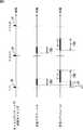
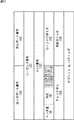
かかる共通のデータ送受信スケジュール(以下通信スケジュールとも称する)の一例が、図2に示されている。 An example of such a common data transmission / reception schedule (hereinafter also referred to as a communication schedule) is shown in FIG.
図2中一番上のタイミングチャートは、データ通信装置1−1によるタイミングパケットTPの送信タイミングの一例を示している。図2の例では、タイミングパケットTPは、時刻t(n)、t(n+1)、t(n+2)、・・・のタイミングで周期的にブロードキャストされている。 The top timing chart in FIG. 2 shows an example of the transmission timing of the timing packet TP by the data communication apparatus 1-1. In the example of FIG. 2, the timing packet TP is periodically broadcast at timings t (n), t (n + 1), t (n + 2),.
データ通信装置1−2乃至1−6は、このタイミングパケットTPを受信し、時刻t(n)、t(n+1)、t(n+2)、・・・に個々のタイマを同期する。具体的には例えば本実施の形態では、後述するように、PLL部34が出力信号rtを出力すること(図5や図6等)が、タイマの同期に相当する。 The data communication apparatuses 1-2 to 1-6 receive this timing packet TP and synchronize the individual timers at times t (n), t (n + 1), t (n + 2),. Specifically, in the present embodiment, for example, as described later, the output of the output signal rt by the PLL unit 34 (FIGS. 5 and 6 and the like) corresponds to timer synchronization.
図2中中央(上から2番目)のタイミングチャートは、データ通信装置1−2乃至1−6における、タイマの示す時刻に基づく送信スケジュールの設定例を示している。また、図2中一番下のタイミングチャートは、データ通信装置1−2乃至1−6における、タイマの示す時刻に基づく受信スケジュールの設定例を示している。データ通信装置1−2乃至1−6における送信機能および受信機能に対応するアプリケーションプログラムは、これらの通信スケジュールに従って動作する。 The timing chart at the center (second from the top) in FIG. 2 shows a transmission schedule setting example based on the time indicated by the timer in the data communication apparatuses 1-2 to 1-6. The timing chart at the bottom in FIG. 2 shows an example of setting a reception schedule based on the time indicated by the timer in the data communication apparatuses 1-2 to 1-6. Application programs corresponding to the transmission function and the reception function in the data communication apparatuses 1-2 to 1-6 operate according to these communication schedules.
送信スケジュールにおいて、時刻t(n)、t(n+1)、t(n+2)、・・・毎に設定されている所定時間TRSは、リアルタイム性を保証すべきデータパケットの送出区間(時間的区間)を示している。そこで、以下、かかる所定時間TRSを、RTP送出区間TRSと称する。 In the transmission schedule, the predetermined time TRS set for each of the times t (n), t (n + 1), t (n + 2),... Is a data packet transmission section (time section) for which real-time performance should be guaranteed. Is shown. Therefore, hereinafter, the predetermined time TRS is referred to as an RTP transmission section TRS.
また、以下、リアルタイム性を保証すべきデータパケットを、リアルタイムパケットRTPという。即ち、リアルタイパケットRTPとは、所定時間内の送受信保証が要求されるデータの一例である。例えば、制御コマンド等が、リアルタイムパケットRTPとして採用可能である。 Hereinafter, a data packet whose real-time property should be guaranteed is referred to as a real-time packet RTP. That is, the real tie packet RTP is an example of data for which transmission / reception guarantee within a predetermined time is required. For example, a control command or the like can be adopted as the real time packet RTP.
一方、受信スケジュールにおいて、時刻t(n)、t(n+1)、t(n+2)、・・・毎に設定されている所定時間TRRは、リアルタイムパケットRTPの受信区間(時間的区間)を示している。そこで、以下、かかる所定時間TRRを、RTP受信区間TRRと称する。 On the other hand, in the reception schedule, the predetermined time TRR set for each of the times t (n), t (n + 1), t (n + 2),... Indicates the reception interval (temporal interval) of the real-time packet RTP. Yes. Therefore, hereinafter, the predetermined time TRR is referred to as an RTP reception period TRR.
RTP送信区間TRSは、例えば、リアルタイムパケットRTPの送信量に応じて設定することができる。一方、RTP受信区間TRRは、LAN(使用する非同期ネットワーク)に固有のパケット到達遅延時間、受信機能のアプリケーションプログラムで設定されるT ’(n)、T ’(n+1)、・・・のタイムアウト、応答確認および通信失敗時の再送処理を実行する通信プロトコルを利用したデータパケット送信の場合における処理時間余裕等に応じて設定することができる。 The RTP transmission section TRS can be set according to the transmission amount of the real-time packet RTP, for example. On the other hand, the RTP reception section TRR is a packet arrival delay time specific to the LAN (asynchronous network to be used), a timeout of T ′ (n), T ′ (n + 1),. It can be set according to a processing time margin or the like in the case of data packet transmission using a communication protocol that executes response confirmation and retransmission processing at the time of communication failure.
ちなみに、期間Δ 1 は、データ通信装置1−1における時刻t(n)、t(n+1)、t(n+2)、・・・に対する、データ通信装置1−2乃至1−6のアプリケーションプログラムが利用するタイマの誤差である。 Incidentally, the
また、期間Δ 2 は、リアルタイムパケットRTPの送出時刻に対する、データ通信装置1−2乃至1−6の受信機能のアプリケーションプログラムにおける受信確認時刻の誤差である。 The
いずれの誤差も、理想的にはゼロであることが望ましい。以下、説明の簡略上、いずれの誤差もゼロであるとして説明していく。 Both errors are ideally zero. In the following, for the sake of simplicity, the description will be made assuming that all errors are zero.
なお、タイミングパケットTPの送信タイミングである時刻t(n)、t(n+1)、t(n+2)、・・・は、必ずしも周期的に発生させる必要はない。例えば、受信機能のアプリケーションプログラムで受信のタイムアウトT ’(n)、T ’(n+1)、・・・の設定が必要となる場合に対応させて非周期的に発生させても良い。 Note that the times t (n), t (n + 1), t (n + 2),... That are the transmission timings of the timing packet TP are not necessarily generated periodically. For example, it may be generated aperiodically in correspondence with the case where it is necessary to set a reception timeout T ′ (n), T ′ (n + 1),.
また、RTP送出区間TRSおよびRTP受信区間TRRは、時刻t(n)、t(n+1)、t(n+2)、・・・毎に、必ずしも一つ設定する必要はない。例えば、複数のデータ通信装置において、時刻t(n)、t(n+1)、t(n+2)、・・・毎に、複数のRTP送出区間TRSと複数のRTP受信区間TRRをそれぞれ個別に設定するように取り決めても良い。 Further, it is not always necessary to set one RTP sending section TRS and RTP receiving section TRR for each time t (n), t (n + 1), t (n + 2),. For example, in a plurality of data communication devices, a plurality of RTP transmission sections TRS and a plurality of RTP reception sections TRR are individually set for each of times t (n), t (n + 1), t (n + 2),. You may negotiate as follows.
このように、非同期ネットワークを利用する情報処理システム(例えば図1)は、1台のデータ通信装置から送出されるタイミングパケットTPで特定される標準時刻を利用して、各データ通信装置における通信スケジュール(例えば図2)を設定し、その通信スケジュールに基づいてデータの送受信を行うことができる。その結果、所定時間内の送受信保証が要求されるデータ(例えばリアルタイムパケットRTP等)の通信が可能になる。 As described above, an information processing system (for example, FIG. 1) using an asynchronous network uses a standard time specified by a timing packet TP transmitted from one data communication device, and uses a communication schedule in each data communication device. (For example, FIG. 2) can be set, and data can be transmitted and received based on the communication schedule. As a result, communication of data (for example, real-time packet RTP) requiring transmission / reception guarantee within a predetermined time becomes possible.
以上説明したように、図1の例では、データ通信装置1−1が、外部からのタイミング信号Rsにより時刻同期情報を得て、それに対応するタイミングパケットTPを送信する装置(以下、TP送信装置と称する)に該当する。一方、データ通信装置1−2乃至1−6が、非同期ネットワークからタイミングパケットTPを受信し、それより時刻同期情報を得る装置(以下、TP受信装置と称する)に該当する。 As described above, in the example of FIG. 1, the data communication device 1-1 obtains time synchronization information from the external timing signal Rs and transmits a timing packet TP corresponding thereto (hereinafter referred to as a TP transmission device). It corresponds to). On the other hand, the data communication devices 1-2 to 1-6 correspond to devices (hereinafter referred to as TP receiving devices) that receive the timing packet TP from the asynchronous network and obtain time synchronization information therefrom.
ただし、データ通信装置1−2乃至1−6も、タイミング信号Rsが入力されれば、TP送信装置として機能することもできるし、データ通信装置1−1もTP受信装置として機能することもできる。即ち、データ通信装置1−1乃至1−6は、TP送信装置としてもTP受信装置としても機能し得るが、タイミング信号Rsが入力される場合にはTP送信装置として機能して、それ以外の場合にはTP受信装置として機能することになる。 However, if the timing signal Rs is input, the data communication devices 1-2 to 1-6 can also function as a TP transmission device, and the data communication device 1-1 can also function as a TP reception device. . That is, the data communication apparatuses 1-1 to 1-6 can function as both a TP transmission apparatus and a TP reception apparatus, but function as a TP transmission apparatus when the timing signal Rs is input. In this case, it functions as a TP receiver.
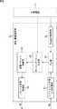
そこで、以下、データ通信装置1−1乃至1−6を個々に区別する必要がない場合、単にデータ通信装置1と称する。かかるデータ通信装置1の機能的構成例が図3に示されている。 Therefore, hereinafter, the data communication apparatuses 1-1 to 1-6 are simply referred to as the
図3の例では、データ通信装置1は、主制御部11、時刻情報送信部12、およびデータ送受信部13から構成されている。 In the example of FIG. 3, the
主制御部11は、このデータ通信装置1全体の動作を制御する。その制御に際して、主制御部11は、図示はしないが、上述した受信機能や送信機能の他各種の機能を実現させる各種アプリケーションプログラムを必要に応じて適宜実行する。 The
時刻情報送信部12は、外部からのリファレンス信号Rsに基づいてタイミングパケットTPを生成して、マルチキャストまたはブロードキャスト通信により他のデータ通信装置に送信する。なお、時刻情報送信部12の詳細については図4を参照して後述する。 The time
データ送受信部13は、他のデータ通信装置から送信された、タイミングパケットTPを含む各種データパケット(以下、他のデータ通信装置からのパケットをまとめてパケットPrと称する)を受信し、そのパケットPrを主制御部11に提供したり、そのパケットPrに基づく各種処理を適宜実行する。また、データ送受信部13は、タイミングパケットTPを除く各種パケットを主制御部11から取得したり自身で生成して、そのパケット(以下、パケットPsと称する)を他のデータ通信装置に送信する。なお、データ送受信部13の詳細については図5乃至図12を参照して後述する。 The data transmitting / receiving
次に、図4を参照して、時刻情報送信部12の詳細について説明する。即ち、図4は、時刻情報送信部12の詳細な機能的構成例を示している。 Next, the details of the time
図4の例では、時刻情報送信部12は、リファレンス信号入力処理部21乃至パケット送信処理部26から構成されている。 In the example of FIG. 4, the time
リファレンス信号入力処理部21は、外部からのリファレンス信号Rsを入力し、必要に応じて各種信号処理を適宜施し、PLL部23に提供する。 The reference signal
PLL動作設定部22は、主制御部11から提供される各種設定に関する制御情報に基づいて、PLL部23の動作を設定するための制御情報(以下、PLL部制御情報と称する)を生成して、PLL部23に提供する。 The PLL
PLL部23は、PLL動作設定部22からのPLL部制御情報に基づく制御、即ち、例えばここでは、リファレンス信号入力処理部21の出力信号を比較信号として設定し、出力信号(以下、PLL出力信号と称する)を比較信号と同期させる制御を行う。このPLL出力信号は、タイミングパケット生成部24に提供される。 The
タイミングパケット生成部24は、PLL部23のPLL出力信号に基づいて、タイミングパケットTPを生成して、送信パケット制御部25に提供する。なお、本実施の形態では、タイミングパケットTPには、例えば、後述する図5等のPLL部34の動作に必要なタイミング情報(例えばクロックリファレンス等)やタイミングパケットペイロードの記載情報が含まれており、これらの情報のうちの少なくとも一部は主制御部11から提供される。 The
送信パケット制御部25は、タイミングパケット生成部24からのタイミングパケットTPを、出力タイミングを調整した上でパケット送信処理部26に提供する。 The transmission
パケット送信処理部26は、送信パケット制御部25からのタイミングパケットTPを、非同期ネットワークに適合する形態に変換した上で、当該非同期ネットワークを介して他のデータ通信装置に出力する。なお、非同期ネットワークに適合する形態に変換するとは、例えば、非同期ネットワークがイーサネット(登録商標)である場合には、MACヘッダ等を付加することをいう。 The packet
次に、図5乃至図12を参照して、データ送受信部13の詳細について説明する。 Next, details of the data transmitting / receiving
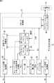
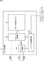
図5は、データ送受信部13の詳細な機能的構成例を示している。 FIG. 5 shows a detailed functional configuration example of the data transmitting / receiving
パケット受信処理部31は、他のデータ通信装置から送信されたパケットPrを、非同期ネットワークを介して受信し、パケットフィルタ部32に提供する。 The packet
パケットフィルタ部32は、予め設定されたアドレス情報に基づいて、パケット受信処理部31からのパケットPrを、タイミングパケットTPとその他のパケットPaとに分離し、タイミングパケットTPをタイミングパケット検出部33に、その他のパケットPaをTCP/IP処理部37に、それぞれ提供する。 The
タイミングパケット検出部33は、パケットフィルタ部32からのタイミングパケットTPから、PLL部34の動作に必要なタイミング情報およびタイミングパケットペイロードの記載情報を検出し、その検出情報等をPLL部制御情報としてPLL部34に提供する。 The
PLL部34は、タイミングパケット検出部33からのPLL部制御情報に基づく制御、即ち、例えばここでは、タイミングパケット検出部33からのタイミング情報を比較信号として設定し、PLL出力信号を比較信号と同期させる制御を行う。このPLL出力信号は、再生タイミング信号rtとして、リアルタイムパケットキューイング用メモリ制御信号生成部35に提供される。 The
リアルタイムパケットキューイング用メモリ制御信号生成部35は、PLL部34からの再生タイミング信号rtに基づいて、リアルタイムパケットキューイング用メモリ36の書き込みや読出しタイミングを制御するための制御信号(以下、メモリ制御信号と称する)を生成して、リアルタイムパケットキューイング用メモリ36に提供する。 The real-time packet queuing memory control signal generation unit 35 controls a write signal and a read timing of the real-time
リアルタイムパケットキューイング用メモリ36は、リアルタイムパケットキューイング用メモリ制御信号生成部35からのメモリ制御信号に基づいて、TCP/IP処理部37から適宜提供される各リアルタイムパケットRTPのそれぞれを書き込む書き込み動作や、その各リアルタイムパケットRTPをRTP送出区間TRS内で読み出す読み出し動作を行う。このような書き込み動作や読み出し動作により、RTP送出区間TRSに送信タイミングが調整された各リアルタイムパケットRTPは、リアルタイムパケットキューイング用メモリ36から送信パケット制御部38に転送される。 The real-time
送信パケット制御部38は、リアルタイムパケットキューイング用メモリ36からのリアルタイムパケットRTPと、TCP/IP処理部37からの非リアルタイムパケットNRTPとを、送信タイミングをそれぞれ調整して、パケット送信処理部39に提供する。ここに、非リアルタイムパケットNRTPとは、リアルタイム性を保証する必要のないデータパケットのことをいう。即ち、非リアルタイパケットNRTPとは、所定時間内の送受信保証が要求されないデータの一例である。例えば、いわゆるメールのデータや、Webサーバとのやり取り(ファイル転送等)を行うためのデータ等が、非リアルタイパケットNRTPとして採用可能である。 The transmission
また、その際、送信パケット制御部38は、RTP送出区間TRSに送信タイミングが調整されたリアルタイムパケットRTPの入力を優先するためのバッファ動作を行う。 At that time, the transmission
パケット送信処理部39は、送信パケット制御部38からのリアルタイムパケットRTPまたは非リアルタイムパケットNRTPを、非同期ネットワークに適合する形態に変換した上で、パケットPsとして当該非同期ネットワークを介して他のデータ通信装置に出力する。 The packet
TCP/IP処理部37は、その名称の通り、いわゆるTCP/IP(Transmission Control Protocol/Internet Protocol)処理、即ち、TCP層とIP層との間のデータ転送に伴う各種処理等を実行する。この例では、TCP/IP処理部37が、いわゆるTCPパケットを生成し、そのTCPパケットをリアルタイムパケットRTPと非リアルタイムパケットNRTPとに区別して、リアルタイムパケットRTPをリアルタイムパケットキューイング用メモリ36に提供し、また、非リアルタイムパケットNRTPを送信パケット制御部38に提供する。 As the name implies, the TCP /
なお、本実施の形態では、リアルタイムパケットRTPと非リアルタイムパケットNRTPとを区別して指示する情報は、主制御部11が実行するアプリケーションプログラムから与えられ、アプリケーションインタフェース部40を介してTCP/IP処理部37に提供される。そして、TCP/IP処理部37は、かかる情報に基づいて、リアルタイムパケットRTPと非リアルタイムパケットNRTPとを区別する。 In the present embodiment, the information for distinguishing and instructing the real-time packet RTP and the non-real-time packet NRTP is given from the application program executed by the
即ち、アプリケーションインタフェース部40は、主制御部11が実行するユーザーアプリケーションプログラム(アプリケーション層)とTCP/IP処理部37との間の通信を行うための機構である。 That is, the
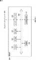
次に、図6を参照して、図5の例のデータ送受信部13の動作の一例を説明する。 Next, an example of the operation of the data transmitting / receiving
ステップS1においては、各再生タイミング信号rtが、周期的な各タイミングパケットTPの受信タイミングに応じて、PLL部34により周期的にその都度生成されて出力される。即ち、図6の例とは、タイミングパケットTPが周期的に受信される例であって、再生タイミング信号rtが、周期的な時刻同期情報として利用される例である。 In step S1, each reproduction timing signal rt is periodically generated and output by the
上述したように、この再生タイミング信号rtに基づいて、メモリ制御信号が、リアルタイムパケットキューイング用メモリ制御信号生成部35により生成されて、リアルタイムパケットキューイング用メモリ36に提供される。 As described above, based on the reproduction timing signal rt, a memory control signal is generated by the real-time packet queuing memory control signal generator 35 and provided to the real-time
本実施の形態では、このメモリ用制御信号には、RTP送出区間TRSを特定するための情報が含まれており、ステップS2において、周期的なRTP送出区間TRSがリアルタイムパケットキューイング用メモリ36により設定される。RTP送出区間TRSは、図6の例では、2つの再生タイミング信号rtの出力時点間のうちの、最初の再生タイミング信号rtの出力時点から所定の時間が経過するまでの間とされている。ただし、RTP送出区間TRSは、図6の例に限定されず、上述した通信時間の条件が満たされれば任意の時間的区間でよい。 In the present embodiment, the memory control signal includes information for specifying the RTP transmission section TRS, and the periodic RTP transmission section TRS is determined by the real-time
一方、上述したステップS1とS2とは独立して(特に同期せずに)、ステップS3において、複数のリアルタイムパケットRTPがTCP/IP処理部37により逐次生成されて、リアルタイムパケットキューイング用メモリ36に提供されてくる。 On the other hand, independent of the above-described steps S1 and S2 (without particular synchronization), in step S3, a plurality of real-time packets RTP are sequentially generated by the TCP /
即ち、図6の例では、リアルタイムパケットRTP自体は、RTP送出区間TRSとは無関係に発生されるとした。これは、本実施の形態のTCP/IP処理部37には通信スケジュール管理機能がないこと、また、ユーザアプリケーションに通信スケジュール管理機能を実装することによるユーザアプリケーションのリソース割当に対する負担増加を避けることに起因する。 That is, in the example of FIG. 6, the real-time packet RTP itself is generated regardless of the RTP transmission section TRS. This is because the TCP /
ステップS4において、TCP/IP処理部37からの複数のリアルタイムパケットRTPのそれぞれは、次の周期のRTP送出区間TRSが開始されるまでの間、リアルタイムパケットキューイング用メモリ36にバッファリングされる。 In step S4, each of the plurality of real-time packets RTP from the TCP /
なお、リアルタイムパケットキューイング用メモリ制御信号生成部35からのメモリ用制御信号には、リアルタイムパケットキューイング用メモリ36における、複数のリアルタイムパケットRTPの書き込みアドレス(書き込み指令)が含まれている。 The memory control signal from the real-time packet queuing memory control signal generator 35 includes write addresses (write commands) for a plurality of real-time packets RTP in the real-time
そして、次の周期のRTP送出区間TRSが開始されると、ステップS5において、その直前の周期においてリアルタイムパケットキューイング用メモリ36にバッファリングされている1以上のリアルタイムパケットRTP(図6の例では、2乃至3個のリアルタイムパケットRTP)が、リアルタイムパケットキューイング用メモリ36から読み出され、送信パケット制御部38とパケット送信処理部39とを介して、パケットPsとして非同期ネットワークに送信される。 Then, when the RTP transmission section TRS of the next cycle is started, in step S5, one or more real-time packets RTP (in the example of FIG. 6) buffered in the real-time
なお、リアルタイムパケットキューイング用メモリ制御信号生成部35からのメモリ用制御信号には、リアルタイムパケットキューイング用メモリ36における、次の周期のRTP送出区間TRSに送信すべき1以上のリアルタイムパケットRTPの読み出しアドレス(読み出し指令)が含まれている。 The memory control signal from the real-time packet queuing memory control signal generator 35 includes one or more real-time packet RTPs to be transmitted in the RTP transmission section TRS of the next cycle in the real-time
以上、本発明が適用されるデータ通信装置1のデータ送受信部13の実施の形態として、図5の機能的構成を有するデータ送受信部13について説明した。ただし、データ送受信部13は、図5の例に限定されず、その他様々な実施の形態を取ることが可能である。 The data transmission /
具体的には例えば、図7、図8、および図10のそれぞれには、データ送受信部13の他の実施の形態の機能ブロック図が示されている。なお、図7、図8、および図10のそれぞれにおいて、他の実施の形態と対応する部分(機能ブロックや信号)には対応する符号を付しており、それらの説明については同様の説明となるため、最初に登場する実施の形態において説明し、それ以降の実施の形態においては説明を省略する。即ち、図5の例の実施の形態において説明済みのものは、以下、その説明は省略する。 Specifically, for example, in each of FIGS. 7, 8, and 10, functional block diagrams of other embodiments of the data transmitting / receiving
図7の例のデータ送受信部13では、図5の例の構成に対して、PLL比較信号選択部52がさらに設けられている。 In the data transmission /
PLL比較信号選択部52は、タイミングパケット検出部33の検出情報(図5の例ではPLL部制御情報とされていた情報)、図視せぬ外部からのタイミング信号(PLL比較信号選択部52に引かれている4本の矢印のうちの左から2番目の矢印)、および、アプリケーションインタフェース部51からの内部タイミング信号(PLL比較信号選択部52に引かれている4本の矢印のうちの左から3番目の矢印)を入力し、そのうちの1つを選択して、PLL部制御情報としてPLL部34に提供する。かかるPLL部制御情報の選択は、アプリケーションインタフェース部51からのPLL比較信号選択制御信号(PLL比較信号選択部52に引かれている4本の矢印のうちの一番右側の矢印)に基づいて行われる。 The PLL comparison
このように、図7の例のデータ送受信部13は、タイミングパケットTPのみならず、それ以外の情報(外部または内部タイミング信号等)を、時刻同期情報として利用することができる。ただし、図7の例のデータ送受信部13は、タイミングパケットTP以外の情報を時刻同期情報として利用可能な実施の形態の例示に過ぎず、上述した3つの入力の全てが揃っていることは必須条件ではない。即ち、例えば、外部タイミング信号のみで動作するデータ送受信部13であってもよい。 As described above, the data transmission /
なお、図7の例のデータ送受信部13の動作は、上述した図6を参照して説明した図5の例の動作と基本的に同様であるので、ここでは、その説明については省略する。 Note that the operation of the data transmitting / receiving
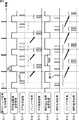
また、図8の例のデータ送受信部13では、図5の例の構成に対して、キューイング用メモリ制御信号生成部35の代わりにキューイング用メモリ制御信号生成部61が設けられ、さらに、非リアルタイムパケットキューイング用メモリ62が設けられている。 Further, in the data transmission /
即ち、図8の例のデータ送受信部13は、リアルタイムパケットキューイング用メモリ36と非リアルタイムパケットキューイング用メモリ62との2つの送信データ蓄積部を有する。 That is, the data transmission /
このため、リアルタイムパケットキューイング用メモリ制御信号生成部61は、PLL部34からの再生タイミング信号rtに基づいて、リアルタイムパケットキューイング用メモリ36に対するメモリ制御信号をリアルタイムパケットキューイング用メモリ36に提供する他、さらに、非リアルタイムパケットキューイング用メモリ62の書き込みや読出しタイミングを制御するためのメモリ制御信号を生成して、非リアルタイムパケットキューイング用メモリ62に提供する。 Therefore, the real-time packet queuing memory
この場合、リアルタイムパケットキューイング用メモリ36は、図5の例と同様に、リアルタイムパケットキューイング用メモリ制御信号生成部61からのメモリ制御信号に基づいて、TCP/IP処理部37から適宜提供される各リアルタイムパケットRTPのそれぞれを書き込む書き込み動作や、その各リアルタイムパケットRTPをRTP送出区間TRS内で読み出す読み出し動作を行う。このような書き込み動作や読み出し動作により、RTP送出区間TRSに送信タイミングが調整された各リアルタイムパケットRTPは、リアルタイムパケットキューイング用メモリ36から送信パケット制御部38に転送される。 In this case, the real-time
一方、非リアルタイムパケットキューイング用メモリ62は、キューイング用メモリ制御信号生成部61からのメモリ制御信号に基づいて、TCP/IP処理部37から適宜提供される各非リアルタイムパケットNRTPのそれぞれを書き込む書き込み動作や、その各非リアルタイムパケットNRTPを、RTP送出区間TRSとは重複しない別の時間的区間(以下、NRTP送出区間TNRSと称する)内で読み出す読み出し動作を行う。このような書き込み動作や読み出し動作により、NRTP送出区間TNRSに送信タイミングが調整された各非リアルタイムパケットNRTPは、非リアルタイムパケットキューイング用メモリ62から送信パケット制御部38に転送される。 On the other hand, the non-real-time
このように、図8の例のデータ送受信部13は、2つのメモリを2つ有し、各々に、リアルタイムパケットRTP、非リアルタイムパケットNRTPをそれぞれ一時蓄積させることができる。ただし、図8の例のデータ送受信部13は、送信データを一時蓄積するメモリを複数有する実施の形態の例示に過ぎず、図8の機能的構成は必須条件ではない。即ち、例えば、リアルタイムパケットRTPをさらに2分類化し、送信データの一時蓄積メモリ部を3つ有するように、データ送受信部13を構成してもよい。 As described above, the data transmission /
次に、図9を参照して、図8の例のデータ送受信部13の動作の一例を説明する。 Next, an example of the operation of the data transmitting / receiving
なお、図9のステップS11乃至S15の処理は、即ち、リアルタイムパケットRTPを送信するまでの一連の処理は、上述した図6のステップS1乃至S5の処理と基本的に同様であるため、ここでは、その説明は省略する。 Note that the processing in steps S11 to S15 in FIG. 9, that is, the series of processing until the real-time packet RTP is transmitted is basically the same as the processing in steps S1 to S5 in FIG. The description is omitted.
上述したように、再生タイミング信号rtに基づいて、非リアルタイムパケットキューイング用メモリ62に対するメモリ制御信号が、キューイング用メモリ制御信号生成部61により生成されて、非リアルタイムパケットキューイング用メモリ62に提供される。 As described above, based on the reproduction timing signal rt, a memory control signal for the non-real time
本実施の形態では、このメモリ用制御信号には、NRTP送出区間TNRSを特定するための情報が含まれており、ステップS16において、周期的なNRTP送出区間TNRSが非リアルタイムパケットキューイング用メモリ62により設定される。NRTP送出区間TNRSは、図6の例では、2つの再生タイミング信号rtの出力時点間のうちの、RTP送出区間TRS終了時点から次の再生タイミング信号rtの出力時点までの間とされている。ただし、NRTP送出区間TNRSは、図9の例に限定されず、RTP送出区間TRSと重複しなければ任意の時間的区間でよい。 In the present embodiment, the memory control signal includes information for specifying the NRTP transmission period TNRS. In step S16, the periodic NRTP transmission period TNRS is changed to the non-real-time
一方、上述したステップS11乃至S16とは独立して(特に同期せずに)、ステップS17において、複数の非リアルタイムパケットNRTPがTCP/IP処理部37により逐次生成されて、非リアルタイムパケットキューイング用メモリ62に提供されてくる。 On the other hand, independently of the above-described steps S11 to S16 (without particular synchronization), in step S17, a plurality of non-real-time packets NRTP are sequentially generated by the TCP /
ステップS18において、TCP/IP処理部37からの複数の非リアルタイムパケットNRTPのそれぞれは、次の周期のNRTP送出区間TNRSが開始されるまでの間、非リアルタイムパケットキューイング用メモリ62にバッファリングされる。 In step S18, each of the plurality of non-real-time packets NRTP from the TCP /
なお、キューイング用メモリ制御信号生成部61から非リアルタイムパケットキューイング用メモリ62へのメモリ制御信号には、非リアルタイムパケットキューイング用メモリ62における、複数の非リアルタイムパケットNRTPの書き込みアドレス(書き込み指令)が含まれている。 Note that a memory control signal from the queuing memory
そして、次の周期のNRTP送出区間TNRSが開始されると、ステップS19において、その直前の周期において非リアルタイムパケットキューイング用メモリ62にバッファリングされている1以上の非リアルタイムパケットNRTP(図9の例では、2乃至3個の非リアルタイムパケットNRTP)が、非リアルタイムパケットキューイング用メモリ62から読み出され、送信パケット制御部38とパケット送信処理部39とを介して、パケットPsとして非同期ネットワークに送信される。 Then, when the NRTP transmission section TNRS of the next cycle is started, in step S19, one or more non-real time packets NRTP (FIG. 9) buffered in the non-real time
なお、キューイング用メモリ制御信号生成部61から非リアルタイムパケットキューイング用メモリ62へのメモリ制御信号には、非リアルタイムパケットキューイング用メモリ62における、次の周期のNRTP送出区間TNRSに送信すべき1以上の非リアルタイムパケットNRTPの読み出しアドレス(読み出し指令)が含まれている。 The memory control signal from the queuing memory
このように、図9の動作の実行により、非リアルタイムパケットNRTPの送信タイミングが、リアルタイムパケットRTPの送信タイミングであるRTP送出区間TRSと重ならないように、NRTP送出区間TNRSの設定が可能になる。 As described above, the execution of the operation in FIG. 9 makes it possible to set the NRTP transmission section TNRS so that the transmission timing of the non-real-time packet NRTP does not overlap with the RTP transmission section TRS that is the transmission timing of the real-time packet RTP.
また、図10の例のデータ送受信部13では、図5の例の構成に対して、TCP/IP処理部37の代わりにTCP/IP処理部71が設けられている。 Further, in the data transmitting / receiving
TCP/IP処理部71は、非リアルタイムパケットNRTPの他に、一時蓄積するリアルタイムパケットRTP(以下、蓄積型リアルタイムパケットRTPbと称する)と一時蓄積しないリアルタイムパケットRTP(以下、非蓄積型リアルタイムパケットRTPaと称する)の2種類のリアルタイムパケットRTPを出力する。蓄積型リアルタイムパケットRTPbは、リアルタイムパケットキューイング用メモリ36に提供される。一方、非蓄積型リアルタイムパケットRTPaは、送信パケット制御部38に提供される。 In addition to the non-real-time packet NRTP, the TCP /
この場合、送信パケット制御部38における送信の優先順位としては、例えば、非蓄積型リアルタイムパケットRTPa、蓄積型リアルタイムパケットRTPb、非リアルタイムパケットNRTPの順に設定されているとする。即ち、蓄積型リアルタイムパケットRTPbに着目すると、リアルタイムパケットキューイング用メモリ36から送信パケット制御部38に蓄積型リアルタイムパケットRTPbが提供されている場合、換言すると、リアルタイムパケットキューイング用メモリ36に蓄積型リアルタイムパケットRTPbが1以上記録されている場合、非蓄積型リアルタイムパケットRTPaが割り込んで送信パケット制御部38に提供されてきたときには、非蓄積型リアルタイムパケットRTPaが優先的に送信パケット制御部38から出力される。これに対して、非リアルタイムパケットNRTPが割り込んで送信パケット制御部38に提供されてきたときには、全ての蓄積型リアルタイムパケットRTPbが出力し終わるまで、非リアルタイムパケットNRTPの出力は禁止される。 In this case, it is assumed that the transmission priority order in the transmission
具体的には例えば図11に示されるように、TCP/IP処理部71は、TCP/IP処理部(コア)81乃至パケット分離制御部84から構成することができる。即ち、図11は、TCP/IP処理部71の機能的構成の詳細例を示している。ただし、図11においては、TCP/IP処理部71が有する各種機能のうち、リアルタイムパケットRTPと非リアルタイムパケットNRTPとの分離機能を実現するための機能ブロックのみが図示されており、その他の機能を実現するための機能ブロックの図示は省略されている。 Specifically, for example, as shown in FIG. 11, the TCP /
TCP/IP処理部(コア)81は、各パケットPを適宜生成してパケット分離部82に提供する。 The TCP / IP processing unit (core) 81 appropriately generates each packet P and provides it to the
パケット分離部82は、パケット分離制御部84の制御に基づいて、TCP/IP処理部(コア)81からの各パケットPを、リアルタイムパケットRTPと非リアルタイムパケットNRTPとに分離し、非リアルタイムパケットNRTPを送信パケット制御部38(図10)に提供する一方、リアルタイムパケットRTPをパケット分離部83に提供する。 Based on the control of the packet
パケット分離部83は、パケット分離制御部84の制御に基づいて、パケット分離部82からの各リアルタイムパケットRTPを、非蓄積型リアルタイムパケットRTPaと蓄積型リアルタイムパケットRTPbとに分離し、非蓄積型リアルタイムパケットRTPaを送信パケット制御部38(図10)に提供する一方、蓄積型リアルタイムパケットRTPbをリアルタイムパケットキューイング用メモリ36(図10)に提供する。 Based on the control of the packet
パケット分離制御部84は、アプリケーションインタフェース部40から提供されるパケット分離制御情報に基づいて、非リアルタイムパケットNRTPとリアルタイムパケットRTPとを特定して分離するための情報(以下、第1のパケット分離情報と称する)を生成し、パケット分離部82に提供する。即ち、パケット分離部82は、第1のパケット分離情報に基づいて、各パケットPを、リアルタイムパケットRTPと非リアルタイムパケットNRTPとに分離する処理を実行する。 The packet
また、パケット分離制御部84は、アプリケーションインタフェース部40から提供されるパケット分離制御情報に基づいて、非蓄積型リアルタイムパケットRTPaと蓄積型リアルタイムパケットRTPbとを特定して分離するための情報(以下、第2のパケット分離情報と称する)を生成し、パケット分離部83に提供する。即ち、パケット分離部83は、第2のパケット分離情報に基づいて、各リアルタイムパケットRTPを、非蓄積型リアルタイムパケットRTPaと蓄積型リアルタイムパケットRTPbとに分離する処理を実行する。 Further, the packet
例えば、リアルタイムパケットRTPが、図12のTCPヘッダ部を有するTCPパケットである場合には、パケット分離制御部84は、図12のTCPヘッダ部のコードビット(図12中灰色表示されている、URG、ACK、PSH、RST、SNY、FINの6ビット)のうち、所定の組み合わせを蓄積型として指示する旨の情報を、第2のパケット分離情報として生成して、パケット分離部83に提供する。 For example, when the real-time packet RTP is a TCP packet having the TCP header portion of FIG. 12, the packet
この場合、パケット分離部83は、分離対象のリアルタイムパケットRTPがTCPパケットの場合、そのパケットのTCPヘッダ部のコードビットが、第2のパケット分離情報が指示する組み合わせであるか否かを判定し、指示する組み合わせであると判定したときには、分離対象のリアルタイムパケットRTPを蓄積型リアルタイムパケットRTPbとして出力し、また、指示する組み合わせでないと判定したときには、分離対象のリアルタイムパケットRTPを非蓄積型リアルタイムパケットRTPaとして出力する。 In this case, when the real-time packet RTP to be separated is a TCP packet, the
また、パケット分離部83は、分離対象のリアルタイムパケットRTPがTCPパケット以外の場合、その分離対象のリアルタイムパケットRTPを非蓄積型リアルタイムパケットRTPaとして出力する。 Further, when the real-time packet RTP to be separated is other than a TCP packet, the
以上説明したTCP/IP処理部71を有する図10の例のデータ送受信部13を採用することで、例えば次のような効果を奏することが可能になる。即ち、例えば、リアルタイムパケットRTPがTCPパケットである場合、コネクション開設時における3シェークハンド動作(SYNパケット−SYN ACKパケット−ACKパケットの通信動作)を実現する場合、これらのパケットを一時蓄積して通信すると通信周期として3周期必要となる。かかる3シェークハンド動作はコネクション閉設時にも発生する。そこで、コネクション開閉を頻繁に行うTCPパケットをリアルタイムパケットRTPとする場合、図10の例のデータ送受信部13を採用することで、即ち、蓄積型リアルタイムパケットRTPbと非蓄積型リアルタイムパケットRTPaとを区別して使用することで、3周期必要であった通信周期は1周期で済むことになり、その結果、3シェークハンド動作をより一段と高速に実現できる、という効果を奏することが可能になる。 By adopting the data transmitting / receiving
以上、本発明が適用される情報処理システムの実施の形態として、図1に示される構成のシステムについて説明したが、本発明は、図1の例に限定されず、その他様々な実施の形態を取ることが可能である。 As described above, the system having the configuration shown in FIG. 1 has been described as an embodiment of the information processing system to which the present invention is applied. However, the present invention is not limited to the example of FIG. It is possible to take.
具体的には例えば、図13と図14のそれぞれには、本発明が適用される情報処理システムの他の実施の形態の機能ブロック図が示されている。 Specifically, for example, each of FIGS. 13 and 14 shows a functional block diagram of another embodiment of an information processing system to which the present invention is applied.
即ち、図13は、非同期ネットワークシステムの他の実施の形態としての、映像信号切換システムへの適用例を示ている。 That is, FIG. 13 shows an application example to a video signal switching system as another embodiment of an asynchronous network system.
図13の例では、垂直同期情報送信装置101、映像信号切替制御装置102、および、映像信号切替装置104−1乃至104−4がLAN-SW103に接続されて構成されている。 In the example of FIG. 13, the vertical synchronization
即ち、図13は、図1の例のデータ通信装置1−1として垂直同期情報送信装置101を採用し、データ通信装置1−2として映像信号切替制御装置102を採用し、かつ、データ通信装置1−3乃至1−6として映像信号切替装置104−1乃至104−4を採用した場合の情報処理システムの構成例を示している。 That is, FIG. 13 employs the vertical synchronization
映像信号切換装置104−1乃至104−4は、3つの映像入力信号(図13中、各装置を示すブロックに入力される矢印)を選択対象とし、選択した2つの映像信号を映像出力信号(図13中、各装置を示すブロックから出力される矢印)として出力する機能を有する。 The video signal switching devices 104-1 to 104-4 select three video input signals (arrows input to blocks indicating the respective devices in FIG. 13) as selection targets, and the two selected video signals as video output signals ( In FIG. 13, it has a function of outputting as an arrow) output from a block indicating each device.
図13の例では、垂直同期信号がタイミングパケットTPとして垂直同期情報送信装置101から出力され、LAN経由で(LAN-SW103を介して)、映像信号切替制御装置102および映像信号切替装置104−1乃至104−4に与えられる。その結果、この情報処理システムにおいて、共通の垂直同期信号が再生される。この垂直同期信号を共通の時刻情報として、映像信号切換制御装置102および映像信号切換装置104−1乃至104−4は動作する。 In the example of FIG. 13, the vertical synchronization signal is output from the vertical synchronization
ここでは、映像信号切換装置104−1乃至104−4における映像信号の切換は、垂直同期信号のタイミングに連動して実行されるとする。この場合、映像信号切換制御装置102は、映像信号の切替を制御するための制御コマンドを生成し、その制御コマンドをリアルタイムパケットRTPとして、LAN経由で(LAN-SW103を介して)、映像信号切替装置104−1乃至104−4に送信する。即ち、映像信号切替装置104−1乃至104−4は、リアルタイムパケットRTPとして受信される制御コマンドに基づいて動作し、制御コマンドに応じた映像信号の切換処理を実行する。 Here, it is assumed that the video signal switching in the video signal switching devices 104-1 to 104-4 is executed in conjunction with the timing of the vertical synchronization signal. In this case, the video signal
即ち、図13の例では、映像信号の切換を制御する制御コマンドが、所定時間内の送受信保証が要求されるデータの一例である。 That is, in the example of FIG. 13, the control command for controlling the switching of the video signal is an example of data for which transmission / reception guarantee within a predetermined time is required.
また、図13の情報処理システムにおいて、映像信号切替制御装置102として、モニタ機能付きの装置を採用し、映像信号切替装置104−1乃至104−4として、モニタ対応機能付き装置を採用することもできる。 In the information processing system of FIG. 13, a device with a monitor function may be employed as the video signal
ここに、モニタ対応機能とは、映像入力信号及び映像出力信号の中から、モニタ機能付きの映像信号切換制御装置102により指定された映像信号をパケット化して送信する機能のことをいう。また、モニタ機能とは、パケット化した映像信号を受信して表示する機能をいみする。 Here, the monitor corresponding function refers to a function of packetizing and transmitting a video signal designated by the video signal
ここで、表示画像は、垂直同期情報送信装置101からタイミングパケットTPとして送信される垂直同期情報に従って表示されるとする。もっとも、表示画像の切換タイミングは、フィールド単位程度の誤差を許容するものとする。この場合、この映像信号パケットも、リアルタイムパケットTPとして取り扱うことが可能になるが、上述したリアルタイム性を保証すべき制御コマンドとは性質の異なるデータパケットとして取扱うことが可能となる。 Here, it is assumed that the display image is displayed according to the vertical synchronization information transmitted as the timing packet TP from the vertical synchronization
また、図14の例では、情報処理システムの構成要素自体は、上述した他の例と同様に、6台のデータ通信装置1−1乃至1−6とLAN-SW2とされているが、データ通信装置1−1はLAN-SW2に接続されておらず、データ通信装置1−2乃至1−6のみがLAN-SW2に接続されている。 Further, in the example of FIG. 14, the components of the information processing system are the six data communication apparatuses 1-1 to 1-6 and the LAN-
即ち、データ通信装置1−1から送信されたタイミングパケットTPは、LAN-SW2を介さずに直接、データ通信装置1−2乃至1−6に提供される。 That is, the timing packet TP transmitted from the data communication device 1-1 is provided directly to the data communication devices 1-2 to 1-6 without going through the LAN-SW2.
この場合、データ通信装置1−1にとって、データ送受信部13(図3)は必須な構成要素ではない。即ち、データ通信装置1−1は、TP送信装置の専用装置として構成してもよい。 In this case, the data transmitter / receiver 13 (FIG. 3) is not an essential component for the data communication apparatus 1-1. That is, the data communication device 1-1 may be configured as a dedicated device for the TP transmission device.
その他、本発明は、次の(a)乃至(g)で示されるような様々な情報処理システムにも適用可能である。 In addition, the present invention can be applied to various information processing systems as shown in the following (a) to (g).
(a)前述の形態例では、リアルタイム性を保証すべきデータパケットと、リアルタイム性の保証が不要なデータパケットの受信又は送信機能の両方を有するデータ通信装置から構成されるシステムについて説明した。しかしながら、リアルタイム性を保証すべきデータパケットだけを送受信する情報処理装置と、リアルタイム性の保証が不要なデータパケットだけを送受信する情報処理装置から構成される非同期ネットワークシステムにも適用できる。 (A) In the above-described embodiment, a system constituted by a data communication apparatus having both a data packet for which real-time property is to be guaranteed and a data packet reception or transmission function that does not require real-time property has been described. However, the present invention can also be applied to an asynchronous network system including an information processing apparatus that transmits and receives only data packets that should guarantee real-time performance and an information processing apparatus that transmits and receives only data packets that do not require real-time performance guarantee.
(b)前述の形態例では、映像機器として映像信号切換装置とその切換制御装置が接続されている場合について説明した。しかし、他の映像機器が接続されても良い。例えば、撮像カメラ、監視カメラその他の撮像装置とその制御装置が接続されていても良い。また例えば、ビデオサーバー、ビテオテープレコーダーその他のストレージ装置が接続されていても良い。 (B) In the above-described embodiment, the case where the video signal switching device and the switching control device thereof are connected as the video equipment has been described. However, other video equipment may be connected. For example, an imaging camera, a monitoring camera, or other imaging device and its control device may be connected. Further, for example, a video server, a video tape recorder, or other storage devices may be connected.
(c)前述の形態例では、非同期ネットワークシステムの一例として映像信号切換システムを説明した。そして、非同期ネットワークシステムを構成する情報処理装置の一例として映像機器を接続する場合について説明した。しかし、非同期ネットワークシステムを構成する情報処理装置は他の電子機器でも良い。例えば、スピーカ、チューナー、アンプ、スイッチャその他の音声機器でも良い。 (C) In the above-described embodiment, the video signal switching system has been described as an example of the asynchronous network system. And the case where a video equipment was connected as an example of the information processing apparatus which comprises an asynchronous network system was demonstrated. However, the information processing apparatus constituting the asynchronous network system may be another electronic device. For example, a speaker, a tuner, an amplifier, a switcher, or other audio equipment may be used.
(d)非同期ネットワークシステムは、民生用のネットワークシステムにも、事業者用のネットワークシステムにも応用できる。例えば、放送局システム(すなわち、映像機器として放送機器が接続される場合)や宅内システムにも適用できる。また、拠点間を接続する基幹システムにも適用できる。 (D) The asynchronous network system can be applied to both a consumer network system and an operator network system. For example, the present invention can be applied to a broadcasting station system (that is, when a broadcasting device is connected as a video device) or a home system. It can also be applied to a backbone system that connects bases.
(e)前述の形態例に係る送受信機能は、その応用システムに応じた情報処理装置に搭載できる。例えば、コンピュータ、印刷装置、デジタルカメラ、ゲーム機器、スキャナ、携帯情報端末(携帯型のコンピュータ、携帯電話機、携帯型ゲーム機、電子書籍等)、時計
、画像再生装置(例えば、光ディスク装置、ホームサーバー)、モニタ、テレビジョン受
像器にも搭載できる。なお、送受信機能は、処理ボード、半導体チップその他のハードウエアとして搭載される他、コンピュータ上で実行されるプログラムの形態としても搭載し得る。(E) The transmission / reception function according to the above-described embodiment can be installed in an information processing apparatus corresponding to the application system. For example, a computer, a printing device, a digital camera, a game machine, a scanner, a portable information terminal (a portable computer, a mobile phone, a portable game machine, an electronic book, etc.), a clock, an image reproducing device (for example, an optical disk device, a home server) ), Can also be installed in monitors and television receivers. The transmission / reception function can be mounted as a processing board, a semiconductor chip, or other hardware, or as a program executed on a computer.
(f)前述の形態例では、時刻同期情報データ送信装置と情報処理装置が別の場合について説明した。しかし、時刻同期情報データ送信装置は、いずれかの情報処理装置内に搭載されていても良い。 (F) In the above-described embodiment, the case where the time synchronization information data transmission device and the information processing device are different has been described. However, the time synchronization information data transmission device may be mounted in any information processing device.
(g)前述の形態例には、発明の趣旨の範囲内で様々な変形例が考えられる。また、本明細書の記載に基づいて創作される各種の変形例及び応用例も考えられる。 (G) Various modifications can be considered for the above-described embodiments within the scope of the gist of the invention. Various modifications and application examples created based on the description of the present specification are also conceivable.
ところで、上述した一連の処理(或いはそのうちの一部分の処理)は、ハードウエアにより実行させることもできるが、ソフトウエアにより実行させることもできる。 By the way, the above-described series of processes (or a part of them) can be executed by hardware, but can also be executed by software.
この場合、上述した各種情報処理システムの一構成要素、例えば、図1のデータ通信装置1−1乃至1−6の全体若しくはその一部分は、例えば、図15に示されるようなコンピュータで構成することができる。 In this case, one component of the various information processing systems described above, for example, the whole or a part of the data communication apparatuses 1-1 to 1-6 in FIG. 1 is configured by, for example, a computer as shown in FIG. Can do.
図15において、CPU(Central Processing Unit)201は、ROM(Read Only Memory)202に記録されているプログラム、または記憶部208からRAM(Random Access Memory)203にロードされたプログラムに従って各種の処理を実行する。RAM203にはまた、CPU201が各種の処理を実行する上において必要なデータなども適宜記憶される。 In FIG. 15, a CPU (Central Processing Unit) 201 executes various processes according to a program recorded in a ROM (Read Only Memory) 202 or a program loaded from a
CPU201、ROM202、およびRAM203は、バス204を介して相互に接続されている。このバス204にはまた、入出力インターフェース205も接続されている。 The
入出力インターフェース205には、キーボード、マウスなどよりなる入力部206、ディスプレイなどよりなる出力部207、ハードディスクなどより構成される記憶部208、および、通信部209が接続されている。 Connected to the input /
通信部209は、CPU201から供給されるデータを、LAN−SW2を介して、それに接続されている他の機器(上述した例では、他のデータ通信装置1)に送信したり、他の機器から送信されてくるデータを受信し、CPU201に供給したりする。また、通信部209は、例えば、TCP/IP(Transmission Control Protocol/Internet Protocol)などのプロトコルスタックの処理(プロトコルスタックに関する所定の処理)を行う。 The
かかる通信部209は、例えば図16に示すように構成することができる。即ち、図16は、通信部209のハードウエアの構成例を示している。 The
通信部209は、CPU301、ROM302、RAM303、記録部305、インターフェース306、および送受信処理部307を含むようにして構成される。CPU301、ROM302、RAM303、記録部305、インターフェース306、および送受信処理部307のそれぞれは、バス304を介して相互に接続されている。 The
図16の例の通信部309において、CPU301は、ROM302に記憶されているプログラム、または記録部305からRAM303にロードされたプログラムにしたがって各種の処理を実行する。RAM303にはまた、CPU301が各種の処理を実行する上において必要なデータなども適宜記憶される。 In the communication unit 309 in the example of FIG. 16, the
送受信処理部307は、CPU301の制御の基に、例えば、LAN−SW2を介して、他の機器にデータを送信したり、他の機器から送信されてくるデータを受信したりするための所定の処理を行う。 Based on the control of the
通信部209が、図16のようなハードウエア構成を有している場合には、上述した図3の時刻情報送信部12とデータ送受信部13の機能を通信部209に搭載することもできる。即ち、通信部209のCPU301が、時刻情報送信部12とデータ送受信部13との機能を実現するための処理を実行することができる。 When the
この場合、通信部209は、データ通信装置1の一構成要素と把握してもよいが、1つの装置として把握することも可能である。即ち、例えば、図16の通信部209を、図15のデータ通信装置1から着脱自在な装置として構成することも可能である。この場合、通信部209は、データ通信装置1のみならず様々な機器に装着されて、ネットワーク通信を行うための上述した各種処理を実行することができる。 In this case, the
図15に戻り、入出力インターフェース205にはまた、必要に応じてドライブ210が接続され、磁気ディスク、光ディスク、光磁気ディスク、或いは半導体メモリなどよりなるリムーバブル記録媒体211が適宜装着され、それらから読み出されたコンピュータプログラムが、必要に応じて記憶部208にインストールされる。 Returning to FIG. 15, a
一連の処理をソフトウエアにより実行させる場合には、そのソフトウエアを構成するプログラムが、専用のハードウエアに組み込まれているコンピュータ、または、各種のプログラムをインストールすることで、各種の機能を実行することが可能な、例えば汎用のパーソナルコンピュータなどに、ネットワークや記録媒体からインストールされる。 When a series of processing is executed by software, a program constituting the software executes various functions by installing a computer incorporated in dedicated hardware or various programs. For example, a general-purpose personal computer is installed from a network or a recording medium.
このようなプログラムを含む記録媒体は、図15や図16に示されるように、装置本体とは別に、ユーザにプログラムを提供するために配布される、プログラムが記録されている磁気ディスク(フロッピディスクを含む)、光ディスク(CD-ROM(Compact Disk-Read Only Memory),DVD(Digital Versatile Disk)を含む)、光磁気ディスク(MD(Mini-Disk)を含む)、もしくは半導体メモリなどよりなるリムーバブルメディア(パッケージメディア)211により構成されるだけでなく、装置本体に予め組み込まれた状態でユーザに提供される、プログラムが記録されている図15のROM202,図16のROM302や、図15の記憶部208,図16の記録部305に含まれるハードディスクなどで構成される。 As shown in FIGS. 15 and 16, the recording medium containing such a program is distributed to provide a program to the user separately from the apparatus main body, and is a magnetic disk (floppy disk) on which the program is recorded. Media), optical disks (including compact disk-read only memory (CD-ROM), DVDs (digital versatile disk)), magneto-optical disks (including MD (mini-disk)), or semiconductor memory (Package medium) 211. The
なお、本明細書において、記録媒体に記録されるプログラムを記述するステップは、その順序に沿って時系列的に行われる処理はもちろん、必ずしも時系列的に処理されなくとも、並列的あるいは個別に実行される処理をも含むものである。 In the present specification, the step of describing the program recorded on the recording medium is not limited to the processing performed in chronological order according to the order, but is not necessarily performed in chronological order, either in parallel or individually. The process to be executed is also included.
また、上述したように、本明細書において、システムとは、複数の処理装置や処理部により構成される装置全体を表すものである。 In addition, as described above, in this specification, the system represents the entire apparatus including a plurality of processing apparatuses and processing units.
また、送信データを一時的に蓄積するメモリ(図5等のリアルタイムパケットユーイング用メモリ36や、図7の非リアルタイムパケットキューイング用メモリ62)の配置位置は、上述した例ではTCP/IP処理部37または71の後段、即ち、いわゆるTCP/IPにおけるIP層とされているが、上述した例に限定されず、任意の位置でよい。ただし、好適な位置は、上述した例のように、TCP/IPにおけるIP層よりも下層レイヤの位置となる。メモリに蓄積するデータ量が少なくなるというメリットと、TCP/IP処理部に近いので、TCP/IP処理部と同一のデバイスにメモリを納めることができるというメリットとがあるからである。 In addition, in the above-described example, the arrangement position of the memory for temporarily storing transmission data (the real-time
1,1−1乃至1−6 データ通信装置, 2 LAN-SW, 11 主制御部, 12 時刻情報送信部, 13 データ送受信部, 31 パケット受信処理部, 32 パケットフィルタ部, 33 タイミングパケット検出部, 34 PLL部, 35 リアルタイムパケットキューイング用メモリ制御信号生成部, 36 リアルタイムパケットキューイング用メモリ, 37 TCP/IP処理部, 38 送信パケット制御部, 39 パケット送信処理部, 40,51 アプリケーションインタフェース部, 52 PLL比較信号選択部, 61 キューイング用メモリ制御信号生成部, 62 非リアルタイムパケットキューイング用メモリ, 71 TCP/IP処理部,81 TCP/IP処理部(コア), 82 パケット分離部, 83 パケット分離部, 84 パケット分離制御部, 101 垂直同期情報送信装置, 102 映像信号切替制御装置, 103 LAN-SW, 104−1乃至104−4 映像信号切替装置, 201 CPU, 202 ROM, 203 RAM, 208 記憶部, 209 通信部, 211 リムーバブルメディア, 301 CPU, 302 ROM, 303 RAM, 308 記録部 1, 1-1 to 1-6 Data communication device, 2 LAN-SW, 11 Main control unit, 12 Time information transmission unit, 13 Data transmission / reception unit, 31 Packet reception processing unit, 32 Packet filter unit, 33 Timing packet detection unit , 34 PLL section, 35 Real-time packet queuing memory control signal generation section, 36 Real-time packet queuing memory, 37 TCP / IP processing section, 38 Transmission packet control section, 39 Packet transmission processing section, 40, 51 Application interface section , 52 PLL comparison signal selection unit, 61 Queuing memory control signal generation unit, 62 Non-real time packet queuing memory, 71 TCP / IP processing unit, 81 TCP / IP processing unit (core), 82 Packet separation unit, 83 Packet separation unit, 84 packet separation system Control unit, 101 vertical synchronization information transmission device, 102 video signal switching control device, 103 LAN-SW, 104-1 to 104-4 video signal switching device, 201 CPU, 202 ROM, 203 RAM, 208 storage unit, 209 communication unit , 211 Removable media, 301 CPU, 302 ROM, 303 RAM, 308 Recording unit
Claims (8)
Translated fromJapanese前記時刻同期情報に基づいて、送信データの送信タイミングを含むスケジュールを設定する設定手段と、
前記設定手段により設定された前記スケジュールにおける前記送信タイミングまでの間、前記送信データを一時蓄積する蓄積手段と、
前記設定手段により設定された前記スケジュールにおける前記送信タイミングで、前記送信データを前記蓄積手段から読み出して、送信することを制御する送信制御手段と
を備える情報処理装置。In an information processing system configured by connecting a plurality of information processing devices having a time synchronization information sharing function via an asynchronous network, one of the plurality of information processing devices,
Setting means for setting a schedule including transmission timing of transmission data based on the time synchronization information;
Storage means for temporarily storing the transmission data until the transmission timing in the schedule set by the setting means;
An information processing apparatus comprising: a transmission control unit that controls reading and transmission of the transmission data from the storage unit at the transmission timing in the schedule set by the setting unit.
前記蓄積手段は、前記TCP/IPにおけるIP層よりも下層レイヤに配置される
請求項1に記載の情報処理装置。The communication protocol of the asynchronous network system is TCP / IP (Transmission Control Protocol / Internet Protocol),
The information processing apparatus according to claim 1, wherein the storage unit is arranged in a lower layer than an IP layer in the TCP / IP.
前記情報処理装置は、前記送信データを前記蓄積手段に蓄積させるか否かの選択をTCPパケット単位で行う選択手段をさらに備え、
前記送信制御手段は、さらに、前記選択手段により蓄積させないと選択された前記TCPパケットについては、所定の規則に従って送信することを制御する
請求項2に記載の情報処理装置。The storage means stores the transmission data in the form of TCP packets,
The information processing apparatus further comprises selection means for selecting whether to store the transmission data in the storage means on a TCP packet basis,
The information processing apparatus according to claim 2, wherein the transmission control unit further controls transmission of the TCP packet selected not to be accumulated by the selection unit according to a predetermined rule.
前記蓄積手段は、前記複数種類のそれぞれの送信データを個別に蓄積する複数の個別蓄積手段を有する
請求項1に記載の情報処理装置。The transmission data is classified into a plurality of types with different transmission timings,
The information processing apparatus according to claim 1, wherein the storage unit includes a plurality of individual storage units that individually store the plurality of types of transmission data.
前記情報処理装置の外部から与えられた前記時刻同期情報を取得する取得手段と、
前記時刻同期情報を発生させる発生手段と
をさらに備える請求項1に記載の情報処理装置。The time synchronization information is a timing signal generated outside the information processing apparatus or inside the information processing apparatus,
Acquisition means for acquiring the time synchronization information given from outside the information processing apparatus;
The information processing apparatus according to claim 1, further comprising: generating means for generating the time synchronization information.
前記時刻同期情報を受信する受信手段
をさらに備える請求項1に記載の情報処理装置。The time synchronization information is information transmitted as a packet from another information processing device among the plurality of information processing devices via the asynchronous network,
The information processing apparatus according to claim 1, further comprising: a receiving unit that receives the time synchronization information.
前記時刻同期情報に基づいて、送信データの送信タイミングを含むスケジュールを設定し、
前記スケジュールにおける前記送信タイミングまでの間、前記送信データを一時蓄積し、
前記スケジュールにおける前記送信タイミングで、それまでの間一時蓄積されていた前記送信データを送信する
ステップを含む情報処理方法。In an information processing system configured by connecting a plurality of information processing devices having a time synchronization information sharing function via an asynchronous network, the information processing method is one of the plurality of information processing devices,
Based on the time synchronization information, set a schedule including the transmission timing of transmission data,
Until the transmission timing in the schedule, temporarily store the transmission data,
An information processing method including a step of transmitting the transmission data that has been temporarily stored until then at the transmission timing in the schedule.
前記時刻同期情報に基づいて、送信データの送信タイミングを含むスケジュールを設定し、
前記スケジュールにおける前記送信タイミングまでの間、制御対象の前記情報処理装置が前記送信データを一時蓄積することを制御し、
前記スケジュールにおける前記送信タイミングで、制御対象の前記情報処理装置が、それまでの間一時蓄積されていた一時蓄積していた前記送信データを送信することを制御する
ステップを含むプログラム。A program that is executed by a computer that controls one of a plurality of information processing apparatuses in an information processing system configured by connecting a plurality of information processing apparatuses having a time synchronization information sharing function via an asynchronous network. And
Based on the time synchronization information, set a schedule including the transmission timing of transmission data,
Controls that the information processing apparatus to be controlled temporarily stores the transmission data until the transmission timing in the schedule,
A program including a step of controlling the information processing apparatus to be controlled to transmit the transmission data that has been temporarily accumulated until then at the transmission timing in the schedule.
Priority Applications (1)
| Application Number | Priority Date | Filing Date | Title |
|---|---|---|---|
| JP2006017206AJP2007201757A (en) | 2006-01-26 | 2006-01-26 | Information processing apparatus and method, and program |
Applications Claiming Priority (1)
| Application Number | Priority Date | Filing Date | Title |
|---|---|---|---|
| JP2006017206AJP2007201757A (en) | 2006-01-26 | 2006-01-26 | Information processing apparatus and method, and program |
Publications (1)
| Publication Number | Publication Date |
|---|---|
| JP2007201757Atrue JP2007201757A (en) | 2007-08-09 |
Family
ID=38455899
Family Applications (1)
| Application Number | Title | Priority Date | Filing Date |
|---|---|---|---|
| JP2006017206AWithdrawnJP2007201757A (en) | 2006-01-26 | 2006-01-26 | Information processing apparatus and method, and program |
Country Status (1)
| Country | Link |
|---|---|
| JP (1) | JP2007201757A (en) |
Cited By (1)
| Publication number | Priority date | Publication date | Assignee | Title |
|---|---|---|---|---|
| CN111095137A (en)* | 2018-01-22 | 2020-05-01 | 欧姆龙株式会社 | Control device, control method, and control program |
- 2006
- 2006-01-26JPJP2006017206Apatent/JP2007201757A/ennot_activeWithdrawn
Cited By (2)
| Publication number | Priority date | Publication date | Assignee | Title |
|---|---|---|---|---|
| CN111095137A (en)* | 2018-01-22 | 2020-05-01 | 欧姆龙株式会社 | Control device, control method, and control program |
| CN111095137B (en)* | 2018-01-22 | 2023-08-08 | 欧姆龙株式会社 | Control device, control method, and storage medium |
Similar Documents
| Publication | Publication Date | Title |
|---|---|---|
| JP4186911B2 (en) | Asynchronous network system, information processing apparatus, data communication management method, and program | |
| EP2628305B1 (en) | Distributed playback architecture for media data using beacon packets for synchronisation | |
| US9479584B2 (en) | Synchronous media rendering of demuxed media components across multiple devices | |
| JP5005895B2 (en) | Strategies for transmitting in-band control information | |
| EP2413564B1 (en) | Method and apparatus for transmitting and receiving streaming data based on RTSP sessions | |
| EP3868043B1 (en) | Wireless audio synchronization | |
| JP4514798B2 (en) | Relay device, relay method, and relay processing program | |
| JP2007201756A (en) | Information processing apparatus and method, and program | |
| JP4564350B2 (en) | Signal processing device | |
| US20170019353A1 (en) | Two tier multiple sliding window mechanism for multidestination media applications | |
| JP2007201757A (en) | Information processing apparatus and method, and program | |
| KR20140066208A (en) | Method of saving content to a file on a server and corresponding device | |
| JP5562436B2 (en) | Video signal output method and video information reproducing apparatus | |
| JP4482043B2 (en) | Digital broadcast retransmission apparatus and method | |
| JP2019211638A (en) | Processing device, output device, synchronization control system, and these control methods, as well as programs | |
| JP6684433B2 (en) | Transmission device, transmission method, and program | |
| JP2023025728A (en) | Material transfer device, material transfer method and material transfer program | |
| JP5472948B2 (en) | Video server | |
| KR20080024310A (en) | Packetizer, Depacketizer, and Playback Time Processing Method in Wireless Networks | |
| JP2005039705A (en) | Asynchronous camera system | |
| JP2008016905A (en) | Content transmission device, content reception device, and content distribution method | |
| JP2008092391A (en) | Recording stream generating method, reproducing method thereof, recording apparatus, and reproducing apparatus | |
| JP2006135613A (en) | Asynchronous network system, synchronous information transmission device, and synchronizing method and program of asynchronous network system | |
| JP2005167800A (en) | Data communication device | |
| JP2010219669A (en) | Video server |
Legal Events
| Date | Code | Title | Description |
|---|---|---|---|
| A300 | Application deemed to be withdrawn because no request for examination was validly filed | Free format text:JAPANESE INTERMEDIATE CODE: A300 Effective date:20090407 |