JP2007201727A - Portable telephone with television telephone function - Google Patents
Portable telephone with television telephone functionDownload PDFInfo
- Publication number
- JP2007201727A JP2007201727AJP2006016809AJP2006016809AJP2007201727AJP 2007201727 AJP2007201727 AJP 2007201727AJP 2006016809 AJP2006016809 AJP 2006016809AJP 2006016809 AJP2006016809 AJP 2006016809AJP 2007201727 AJP2007201727 AJP 2007201727A
- Authority
- JP
- Japan
- Prior art keywords
- camera
- display unit
- mobile phone
- microphone
- videophone
- Prior art date
- Legal status (The legal status is an assumption and is not a legal conclusion. Google has not performed a legal analysis and makes no representation as to the accuracy of the status listed.)
- Withdrawn
Links
- 238000004891communicationMethods0.000claimsabstractdescription28
- 238000001514detection methodMethods0.000claimsdescription26
- 230000005540biological transmissionEffects0.000claimsdescription9
- 230000005236sound signalEffects0.000claimsdescription6
- 238000000034methodMethods0.000claimsdescription3
- 230000002194synthesizing effectEffects0.000claims1
- 238000010586diagramMethods0.000description9
- 230000001413cellular effectEffects0.000description2
- 238000005516engineering processMethods0.000description2
- 241000282412HomoSpecies0.000description1
- 230000003213activating effectEffects0.000description1
Images


Landscapes
- Mobile Radio Communication Systems (AREA)
- Telephone Function (AREA)
- Telephonic Communication Services (AREA)
- Two-Way Televisions, Distribution Of Moving Picture Or The Like (AREA)
Abstract
Description
Translated fromJapanese本発明は、テレビ電話機能付き携帯電話機に関し、特に、電話機筐体の正面側と背面側にそれぞれカメラ及び表示部を備えたテレビ電話機能付き携帯電話機におけるカメラ及び表示部の切り換え技術に関する。 The present invention relates to a mobile phone with a videophone function, and more particularly, to a technology for switching between a camera and a display unit in a mobile phone with a videophone function that includes a camera and a display unit on the front side and the back side of a telephone housing.
最近のテレビ電話機能付き携帯電話機は、電話機筐体の正面側と背面側にそれぞれカメラ及び表示部を備えているものが多く、利用者はテレビ電話中にキー操作にて、正面側のカメラと背面側のカメラを切り換えることができ、正面側のカメラは利用者自身の撮影用、背面側のカメラは風景等の撮影用に用途が分かれている。また、このような2つのカメラを搭載するテレビ電話機能付き携帯電話機では、これら2つのカメラを異なる性能とし、背面側に搭載されているカメラを高性能なカメラとしているものが多い。 Many recent mobile phones with a videophone function are equipped with a camera and a display on the front side and the back side of the phone casing, respectively. The camera on the back side can be switched, and the camera on the front side is divided for the user's own shooting, and the camera on the back side is divided for shooting the landscape. Further, in many mobile phones with a videophone function equipped with such two cameras, these two cameras have different performances, and the camera mounted on the back side is a high-performance camera.
通常、テレビ電話機能付き携帯電話機によるテレビ電話では、電話機筐体正面側のカメラと表示部が起動され、電話機筐体正面と対向する利用者を正面側のカメラで撮影するとともに、正面側の表示部に通信相手側の画像および利用者を表示する状態で使用される。そのため、テレビ電話中に背面側の高性能なカメラで利用者自身を撮影しながらテレビ電話をしようとしても、通常、背面側の表示部には通話の相手及び利用者自身が映らないので、背面側のカメラで利用者自身を撮影しながら通話を行うには不便であり、また、2つのカメラの切り換えを行うにはその都度切り換え操作をしなければならず、操作も面倒である。 Usually, in a videophone using a mobile phone with a videophone function, a camera and a display unit on the front side of the phone case are activated, and a user facing the front side of the phone case is photographed with a front side camera and a front side display is displayed. It is used in a state where the image and user of the communication partner are displayed on the part. Therefore, even if you try to make a videophone call while taking a picture of the user with a high-performance camera on the back side during a videophone call, usually the other party and the user are not shown on the display on the backside. It is inconvenient to make a call while photographing the user with the camera on the side, and to switch between the two cameras, the switching operation must be performed each time, and the operation is troublesome.
例えば、特許文献1では、筐体の正面側と背面側にそれぞれカメラを備えたテレビ電話機能付き携帯電話機を用いてテレビ電話をしようとする際に、そのいずれか一方のカメラあるいは両方のカメラを、使用カメラとして適宜選択できるように構成し、テレビ電話中に、周りの風景を撮って相手に送りたくなれば、撮影ボタンを操作することにより背面側のカメラで風景を撮影すると同時に、その新たに撮影された画像を確認しながら相手に送信することを可能とし、また、TV会議システムとして使用して、背面側のカメラで会議場全体の画像を映している場合に、撮影ボタンを押して発言者が発話することにより正面側のカメラで発言者を撮影し、相手には発言者の画像がウインドウ表示されることにより誰が発言しているのかを容易に確認できるようにする技術が示されている。 For example, in
特許文献1に記載の発明によれば、筐体正面側のカメラで自分を撮影しながらテレビ電話をしている最中に、周りの風景を撮って相手に送りたくなれば、撮影ボタンを操作することにより背面側のカメラで風景を撮影すると同時に、その新たに撮影された画像を確認しながら相手に送信することができ、また、TV会議システムとして使用して、背面側のカメラで会議場全体の画像を映している場合に、撮影ボタンを押して発言者が発話することにより正面側のカメラで発言者を撮影し、相手に送ることはできるが、この発明では、テレビ電話中に撮影された画像は筐体表面側に設けられた表示画面で表示される構成となっているので、テレビ電話中に筐体背面側のカメラで利用者自身を撮影しながらテレビ電話を行うのは、極めて不便である。 According to the invention described in
特許文献1ではそのような使用形態については考慮されておらず、また、カメラの切り替えを行う際には手動で切り替え操作を行うことを前提としている。さらに、当該携帯電話機側にいる2人の話者が、正面側のカメラと背面側のカメラを同時に使用して、相手側との間で3者によるテレビ電話をするような使用形態については全く考慮されていない。
本発明の目的は、電話機筐体の正面側と背面側にそれぞれカメラ及び表示部を備えたテレビ電話機能付き携帯電話機でテレビ電話をする際に、正面側および背面側のどちらのカメラでも任意に使用してかつ違和感なくテレビ電話通話を行うことができる手段を提供することにある。 The object of the present invention is to arbitrarily use either the front side camera or the back side camera when making a videophone call with a mobile phone with a videophone function that includes a camera and a display unit on the front side and the back side of the phone case. It is an object of the present invention to provide a means that can be used and can make a videophone call without feeling uncomfortable.
本発明の他の目的は、例えば2人の人間が、当該携帯電話機の正面側のカメラと背面側のカメラでそれぞれ自らを撮影しながら、相手側携帯電話機との間で3者によるテレビ電話をするような使用形態にも対応可能な手段を提供することにある。 Another object of the present invention is that, for example, two people take a videophone call with a partner mobile phone while taking a picture of themselves with the front camera and the rear camera of the mobile phone. It is an object of the present invention to provide means that can cope with such usage patterns.
本発明のテレビ電話機能付き携帯電話機は、電話機筐体の正面側に配置された、第1のカメラ、第1の表示部、第1のマイク、および該正面と対向する所定範囲内に位置している人間を検出したときに検出信号を出力する第1の動態センサと、前記電話機筐体の背面側に配置された、第2のカメラ、第2の表示部、第2のマイク、および該背面と対向する所定範囲内に位置している人間を検出したときに検出信号を出力する第2の動態センサと、テレビ電話通信中に、前記第1の動態センサから前記検出信号が出力されているときには前記第1のカメラおよび第1の表示部を起動して画像信号を処理し、前記第2の動態センサから前記検出信号が出力されているときには前記第2のカメラおよび第2の表示部を起動して画像信号を処理する画像処理手段と、前記第1及び第2のマイクで集音された音声信号を処理する音声処理手段を備えていることを特徴としている。 The mobile phone with a videophone function of the present invention is located within a predetermined range facing the front, the first camera, the first display unit, the first microphone, which are arranged on the front side of the phone casing. A first dynamic sensor that outputs a detection signal when a human being is detected, a second camera, a second display unit, a second microphone, and A second dynamic sensor that outputs a detection signal when a person located within a predetermined range facing the back surface is detected; and the detection signal is output from the first dynamic sensor during videophone communication. The first camera and the first display unit are activated to process the image signal, and when the detection signal is output from the second dynamic sensor, the second camera and the second display unit To start image processing A processing unit, is characterized in that it comprises a speech processing means for processing the audio signal collected by the first and second microphones.
本発明のテレビ電話機能付き携帯電話機によれば、利用者の使用シーンに応じて、電話機筐体の正面側と背面側にそれぞれ配置されたカメラ及び表示部の使用を自動的に切り換えることができ、テレビ電話の利便性を改善することができる。 According to the mobile phone with a videophone function of the present invention, it is possible to automatically switch the use of the camera and the display unit respectively arranged on the front side and the back side of the phone case according to the usage scene of the user. , Video phone convenience can be improved.
また、前記音声処理手段は、前記第1の動態センサから前記検出信号が出力されているときには前記第1のマイクで集音した音声信号を送話信号として出力し、前記第2の動態センサから前記検出信号が出力されているときには前記第2のマイクで集音した音声信号を送話信号として出力する機能を有する構成とすることができる。 The voice processing means outputs a voice signal collected by the first microphone as a transmission signal when the detection signal is outputted from the first dynamic sensor, and from the second dynamic sensor. When the detection signal is output, the audio signal collected by the second microphone can be output as a transmission signal.
また、前記画像処理手段は、テレビ電話通信中、前記第1の動態センサおよび前記第2の動態センサから前記検出信号が出力されているときには、前記第1のカメラ、第1の表示部、および前記第2のカメラ、第2の表示部の両方を起動し、前記第1の表示部には通信相手側から送信された画像と前記第1のカメラで撮影された画像を表示し、前記第2の表示部には前記通信相手側から送信された画像と前記第2のカメラで撮影された画像を表示する機能を有する構成とすることができる。 Further, the image processing means is configured such that, during the videophone communication, when the detection signal is output from the first dynamic sensor and the second dynamic sensor, the first camera, the first display unit, and Both the second camera and the second display unit are activated, and the first display unit displays an image transmitted from the communication partner side and an image taken by the first camera, and The second display unit may have a function of displaying an image transmitted from the communication partner side and an image photographed by the second camera.
また、前記第1のカメラ、第1の表示部、および前記第2のカメラ、第2の表示部の両方が起動されているときには、前記画像処理手段は、前記第1のカメラと前記第2のカメラで撮影した画像信号を、通信相手側のテレビ電話機能付き携帯電話機の表示部に並べて表示するように合成して送信する機能を有する構成とすることができる。 In addition, when both the first camera, the first display unit, the second camera, and the second display unit are activated, the image processing unit includes the first camera and the second camera. The image signal captured by the camera can be combined and transmitted so as to be displayed side by side on the display unit of the mobile phone with the videophone function on the communication partner side.
また、前記第1のカメラ、第1の表示部、および前記第2のカメラ、第2の表示部の両方が起動されているときには、前記音声処理手段は、前記第1のマイクと前記第2のマイクで集音した音声を合成した信号を通信相手側への送話信号として出力する機能を有する構成とすることができる。 In addition, when both the first camera, the first display unit, the second camera, and the second display unit are activated, the sound processing means includes the first microphone and the second microphone. It can be set as the structure which has a function which outputs the signal which synthesize | combined the audio | voice collected with this microphone as a transmission signal to the communicating party side.
本発明のテレビ電話機能付き携帯電話機では、テレビ電話機能付き携帯電話機の正面側と背面側にそれぞれ備えられたカメラ、表示部、およびマイクを、テレビ電話機能付き携帯電話機を使用する利用者の位置によって、正面側のカメラ、表示部、およびマイク、または、背面側のカメラ、表示部、およびマイクに自動的に切り換わるので、利用者は、携帯電話機の正面側と背面側にそれぞれ備えられたカメラ、表示部、およびマイクのどちらを使用しても全く違和感なくテレビ電話をすることができるため、利用者の利便性を改善することができる。 In the mobile phone with a videophone function of the present invention, the camera, the display unit, and the microphone provided on the front side and the back side of the mobile phone with the videophone function are respectively positioned by the user who uses the mobile phone with the videophone function. Automatically switches to the front camera, display, and microphone, or the rear camera, display, and microphone, so that the user is provided on the front and back sides of the mobile phone respectively. Even if any of the camera, the display unit, and the microphone is used, a videophone call can be made without any sense of incongruity, so that convenience for the user can be improved.
また、第1及び第2の動態センサにより携帯電話機の正面側および背面側の両方に人間が検知されているときには、正面側のカメラ、表示部、およびマイクと、背面側のカメラ、表示部、およびマイクが同時に動作状態に制御されるので、例えば2人の人間が、当該携帯電話機を挟んで当該携帯電話機の正面側のカメラと背面側のカメラで自らを撮影しながら、相手側携帯電話機との間で3者によるテレビ電話を行うことができ、テレビ電話機能付き携帯電話機の使用形態を拡げることができる。 Further, when humans are detected on both the front side and the back side of the mobile phone by the first and second dynamic sensors, the front side camera, the display unit, and the microphone, and the back side camera, the display unit, Since the microphone and the microphone are controlled to operate simultaneously, for example, two people take a picture of themselves with the camera on the front side and the camera on the back side of the mobile phone while sandwiching the mobile phone, The three parties can make a videophone call, and the usage modes of the mobile phone with a videophone function can be expanded.
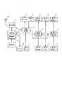
図1は、本発明の実施形態を示すテレビ電話機能付き携帯電話機のブロック図であり、図2は、本実施形態のテレビ電話機能付き携帯電話機の外観図である。 FIG. 1 is a block diagram of a mobile phone with a videophone function according to an embodiment of the present invention, and FIG. 2 is an external view of the mobile phone with a videophone function according to the present embodiment.
本発明のテレビ電話機能付き携帯電話機は、図2のテレビ電話機能付き携帯電話機の外観図に示されているように、正面側(図2(a))にはLCD等からなる第1の表示部1、第1のカメラ3、第1の動態センサ5、第1のマイク7、レシーバ10、キーボードを有する操作部15を備えている。背面側(図2(c))にはLCD等からなる第2の表示部2、第2のカメラ4、第2の動態センサ6、第2のマイク8、スピーカ9を備えている。第1、第2の動態センサとしては、これら動態センサに面する所定の範囲内に位置している人体を検出可能な適宜のセンサ(例えば特許文献2に開示されているような赤外線センサ等)を用いることができる。 As shown in the external view of the mobile phone with a videophone function in FIG. 2, the mobile phone with a videophone function of the present invention has a first display comprising an LCD or the like on the front side (FIG. 2 (a)). 1, a first camera 3, a first
図1において、第1のカメラ3、第1の表示部1、第2のカメラ4、および第2の表示部2は、画像処理部11に接続され、第1のマイク7、第2のマイク8、スピーカ9、およびレシーバ10は、音声処理部12に接続される。また、第1の動態センサ5と第2の動態センサ6は、動態センサ検出部13に接続され、動態センサ検出部13は、前記画像処理部11と音声処理部12に接続される。画像処理部11、音声処理部12、操作部15、およびアンテナ18と接続された送受信部17は、制御部16に接続される。 In FIG. 1, a first camera 3, a
制御部16は、操作部15からの操作指示に基づき、記憶部19に格納されている制御プログラムに従って、本発明のテレビ電話機能付き携帯電話機が有する各種機能を制御する。記憶部19は、本発明のテレビ電話機能付き携帯電話機が有する各種機能を実現するための制御プログラムの記憶、音声あるいは画像データ等制御部16による演算処理に用いられる各種データの一時記憶、電話番号等を登録するために、ROM、RAM、フラッシュメモリ等を含む構成となっている。 Based on an operation instruction from the
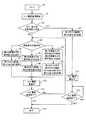
図3は、本実施形態の動作を示すフロー図であり、図4は、本実施形態のテレビ電話機能付き携帯電話機30の、第1のカメラ3、第2のカメラ4、第1の表示部1、第2の表示部2、第1のマイク7、第2のマイク8と使用者40、使用者41の位置関係を示す図である。また、図5〜図7は、本実施形態の動作を説明する概念図である。以下、本実施形態の動作について図1〜図7を参照して説明する。 FIG. 3 is a flowchart showing the operation of the present embodiment. FIG. 4 shows the first camera 3, the
利用者は、本実施形態のテレビ電話機能付き携帯電話機をテレビ電話として使用する際に、第1のカメラ3と第2のカメラ4、第1の表示部1と第2の表示部2を自動で切り換えるモードを利用するか否かを、予め操作部15から設定(ONまたはOFF)する。使用者が設定した内容は制御部16内の記憶部19に記憶される。 When the user uses the cellular phone with the video phone function of the present embodiment as a video phone, the user automatically uses the first camera 3 and the
使用者が、本実施形態のテレビ電話機能付き携帯電話機30の操作部15からテレビ電話通信を開始すると(S2)、テレビ電話機能付き携帯電話機のカメラ、表示部自動切り換え設定がされているか否かが判定され(S3)、カメラ、表示部自動切り換え設定がOFFとされている場合には、音声処理部13は、第1のマイク7、スピーカ9を起動させ、画像処理部11は、携帯電話機30の正面側に配置された第1のカメラ3、第1の表示部1を起動させる(S4)ことにより、通常の使用形態でのテレビ電話通信が行われる(S14)。そしてテレビ電話通信が終了する(S15-YES)と、終了となる(S16)。なお、テレビ電話通信は表示部を見ながら通信を行う関係上、携帯電話機本体は耳から離した状態で使用されるので、受話にはスピーカ9が用いられる。 When the user starts videophone communication from the
一方、(S3)において、カメラ、表示部自動切り換え設定がONとされている場合には使用者の位置判定が行われる(S5)。第1の動態センサ5が使用者a40を感知しているとき(S6)は、この感知信号が動態センサ検出部13に入力され、動態センサ検出部13は検出信号aを画像処理部11と音声処理部12に送出する。画像処理部11は、この検出信号aを受けたときには、筐体正面側に配置されている第1のカメラ3と第1の表示部1を起動させる(S7)。また、音声処理部12は筐体正面側に配置されている第1のマイク7を起動させるとともに、スピーカ9を起動させ、テレビ電話通信が行われる(S12)。 On the other hand, if the camera / display automatic switching setting is ON in (S3), the position of the user is determined (S5). When the
図5はこの時のテレビ電話通信中を示す概念図である。使用者a40により使用されているテレビ電話機能付き携帯電話機A30と使用者c42により使用されているテレビ電話機能付き携帯電話機B31の間で基地局32を介して送受信しており、テレビ電話機能付き携帯電話機A30の第1の表示部1には、通話の相手である使用者c42と、使用者a40(本人)が表示されている。一方、テレビ電話機能付き携帯電話機B31の表示部50には、通話の相手である使用者a40と、使用者c42(本人)が表示されている。 FIG. 5 is a conceptual diagram showing the videophone communication at this time. Transmission / reception is performed between the mobile phone A30 with videophone function used by the user a40 and the mobile phone B31 with videophone function used by the user c42 via the
(S5)において、第2の動態センサ6が使用者b41を感知しているとき(S8)は、この感知信号が動態センサ検出部13に入力され、動態センサ検出部13は検出信号bを画像処理部11と音声処理部12に送出する。画像処理部11はこの検出信号bを受けたときには、筐体背面側に配置されている第2のカメラ4、第2の表示部2を起動させる(S9)。また、音声処理部12は筐体背面側に配置されている第2のマイク8を起動させるとともに、スピーカ9を起動させ、テレビ電話通信中となる(S12)。 In (S5), when the second
図6はこの時のテレビ電話通信中を示す概念図である。使用者b41により使用されているテレビ電話機能付き携帯電話機A30と使用者c42により使用されているテレビ電話機能付き携帯電話機B31の間で基地局32を介して送受信しており、テレビ電話機能付き携帯電話機A30の第2の表示部2には、通話の相手である使用者c42と、使用者b41(本人)が表示されている。一方、テレビ電話機能付き携帯電話機B31の表示部50には、通話の相手である使用者b41と、使用者c42(本人)が表示されている。 FIG. 6 is a conceptual diagram showing the videophone communication at this time. The mobile phone with videophone function is transmitted / received between the mobile phone A30 with videophone function used by the user b41 and the mobile phone B31 with videophone function used by the user c42 via the
また(S5)において、第1の動態センサ5が使用者a40を感知し、第2の動態センサ6が使用者b41を感知しているとき(S10)は、両方の感知信号が動態センサ検出部13に入力され、動態センサ検出部13は検出信号cを画像処理部11と音声処理部12に送出する。画像処理部11はこの検出信号cを受けたときには、筐体の正面側および背面側に配置されている第1のカメラ3および第2のカメラ4、第1の表示部1および第2の表示部2を起動させる(S11)。また、音声処理部12は、筐体の正面側および背面側に配置されている第1のマイク7および第2のマイク8を起動させるとともに、スピーカ9を起動させ、テレビ電話通信中となる(S12)。 In (S5), when the first
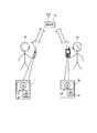
図7はこの時のテレビ電話通信中を示す概念図である。使用者a40及び使用者b41により使用されているテレビ電話機能付き携帯電話機A30と使用者c42により使用されているテレビ電話機能付き携帯電話機B31の間で基地局32を介して送受信しており、テレビ電話機能付き携帯電話機A30の第1の表示部1には通話の相手である使用者c42と使用者a40(本人)が表示され、テレビ電話機能付き携帯電話機A30の第2の表示部2には同じ通話の相手である使用者c42と使用者b41(本人)が表示されている。一方、テレビ電話機能付き携帯電話機B31の表示部50には、通話の相手である使用者a40および使用者b41と、使用者c42(本人)が表示されている。 FIG. 7 is a conceptual diagram showing the videophone communication at this time. The mobile phone A30 with videophone function used by the user a40 and the user b41 and the mobile phone B31 with videophone function used by the user c42 are transmitting and receiving via the
上記第1の動態センサ5と第2の動態センサ6及び動態センサ検出部13により使用者の位置を監視してカメラ、表示部、及びマイクを切り替え制御する動作は、カメラ、表示部自動切り換え設定がONとされているときにはテレビ電話通信が継続されている間実行され、テレビ電話通信が終了する(S13-YES)と、終了となる(S16)。 The first
従って本実施形態によれば、例えば図5に示す使用形態でテレビ電話通信を行っているときに、背面側に搭載されている高性能なカメラ(第2のカメラ4)で撮影した使用者本人a40の画像を通話の相手である使用者c42に送信したい場合、本テレビ電話機能付き携帯電話機を裏返して、該携帯電話機の背面側を使用者本人a40と対向させれば、背面側のカメラ4と表示部2が自動的に起動され、正面側の表示部1に表示されていた通話の相手である使用者c42と使用者b41(本人)の表示も、背面側の表示部2に自動的に切り替わるので、使用者は、テレビ電話使用中に、全く違和感なく携帯電話機の正面側および背面側のカメラを適宜変更して使用しながらテレビ電話を行うことができる。 Therefore, according to the present embodiment, the user himself / herself photographed with the high-performance camera (second camera 4) mounted on the back side, for example, when performing videophone communication in the usage pattern shown in FIG. When it is desired to transmit the image of a40 to the user c42 who is the other party of the call, if the mobile phone with the videophone function is turned over and the back side of the mobile phone faces the user a40, the
また、図7に示すように、当該携帯電話機側にいる2人の話者と相手側との間で3者によるテレビ電話するような使用形態の場合、当該携帯電話機側にいる2人の話者は、携帯電話機を挟んで互いに対面する位置で通話することができるので、2人が正面側のカメラと表示部のみを用いて通話する場合のような窮屈な姿勢を採らされることがなく、楽な姿勢で3者によるテレビ電話をすることができる。 In addition, as shown in FIG. 7, in the case of a usage mode in which a three-party videophone call is made between two speakers on the mobile phone side and the other party, the talks of the two people on the mobile phone side Since the person can talk at a position facing each other with the mobile phone in between, the two persons do not take a cramped posture as in the case of talking using only the front camera and the display unit. You can make a videophone call by 3 parties in an easy posture.
なお上記実施形態では、動態センサ検出部13から出力される判定信号で第1のマイクと第2のマイクも切り替え制御しているが、音声処理部12には動態センサ検出部13から出力される判定信号を入力しないで、第1のマイクと第2のマイクは常時動作状態とし、音声処理部12からは、常時第1のマイクと第2のマイクで集音した音声信号を合成して出力するようにしてもよい。 In the above embodiment, the first microphone and the second microphone are also controlled to be switched by the determination signal output from the dynamic
1 第1の表示部
2 第2の表示部
3 第1のカメラ
4 第2のカメラ
5 第1の動態センサ
6 第2の動態センサ
7 第1のマイク
8 第2のマイク
9 スピーカ
10 レシーバ
11 画像処理部
12 音声処理部
13 動態センサ検出部
15 操作部
16 制御部
17 送受信部
18 アンテナ
19 記憶部
30 テレビ電話装置A
31 相手側テレビ電話装置B
32 基地局
34 ヒンジ部
35 上部筐体
36 下部筐体
40 使用者a
41 使用者b
42 使用者c
50 相手側テレビ電話装置Bの表示部DESCRIPTION OF
31 Opposite videophone device B
32 Base station 34 Hinge part 35 Upper housing 36
41 User b
42 User c
50 Display part of the other party's videophone B
Claims (5)
Translated fromJapaneseWhen the first camera, the first display unit, the second camera, and the second display unit are both activated, the sound processing unit is configured to perform the first microphone and the second microphone. 5. The mobile phone with a videophone function according to claim 3 or 4, wherein the mobile phone has a function of outputting a signal obtained by synthesizing the voice collected in step 1 as a transmission signal.
Priority Applications (1)
| Application Number | Priority Date | Filing Date | Title |
|---|---|---|---|
| JP2006016809AJP2007201727A (en) | 2006-01-25 | 2006-01-25 | Portable telephone with television telephone function |
Applications Claiming Priority (1)
| Application Number | Priority Date | Filing Date | Title |
|---|---|---|---|
| JP2006016809AJP2007201727A (en) | 2006-01-25 | 2006-01-25 | Portable telephone with television telephone function |
Publications (1)
| Publication Number | Publication Date |
|---|---|
| JP2007201727Atrue JP2007201727A (en) | 2007-08-09 |
Family
ID=38455870
Family Applications (1)
| Application Number | Title | Priority Date | Filing Date |
|---|---|---|---|
| JP2006016809AWithdrawnJP2007201727A (en) | 2006-01-25 | 2006-01-25 | Portable telephone with television telephone function |
Country Status (1)
| Country | Link |
|---|---|
| JP (1) | JP2007201727A (en) |
Cited By (22)
| Publication number | Priority date | Publication date | Assignee | Title |
|---|---|---|---|---|
| JP2009044510A (en)* | 2007-08-09 | 2009-02-26 | Ntt Docomo Inc | Mobile device, server, and video playback method in mobile device |
| EP2039399A2 (en) | 2007-08-29 | 2009-03-25 | Nintendo Co., Limited | Imaging apparatus |
| US20100053083A1 (en)* | 2008-09-01 | 2010-03-04 | Jun-Sik Hwang | Portable devices and controlling method thereof |
| US7817142B2 (en) | 2007-08-29 | 2010-10-19 | Nintendo Co., Ltd. | Imaging apparatus |
| US8177441B2 (en) | 2007-08-29 | 2012-05-15 | Nintendo Co., Ltd. | Imaging apparatus |
| US8359547B2 (en) | 2008-10-01 | 2013-01-22 | Nintendo Co., Ltd. | Movable user interface indicator of at least one parameter that is adjustable with different operations for increasing and decreasing the parameter and/or methods of providing the same |
| JP2013524684A (en)* | 2010-04-07 | 2013-06-17 | アップル インコーポレイテッド | Establishing a video conference during a call |
| JP2014003349A (en)* | 2012-06-15 | 2014-01-09 | Kyocera Corp | Terminal device |
| US8848100B2 (en) | 2008-10-01 | 2014-09-30 | Nintendo Co., Ltd. | Information processing device, information processing system, and launch program and storage medium storing the same providing photographing functionality |
| US8913172B2 (en) | 2008-06-13 | 2014-12-16 | Nintendo Co., Ltd. | Information processing apparatus and computer-readable storage medium recording information processing program |
| US9135026B2 (en) | 2008-06-13 | 2015-09-15 | Nintendo Co., Ltd. | Information-processing apparatus having photography applications |
| US9264694B2 (en) | 2007-08-29 | 2016-02-16 | Nintendo Co., Ltd. | Hand-held imaging apparatus and storage medium storing program |
| US11388370B1 (en)* | 2021-03-31 | 2022-07-12 | Motorola Mobility Llc | Dual display dual facing camera video call system |
| US12242707B2 (en) | 2017-05-15 | 2025-03-04 | Apple Inc. | Displaying and moving application views on a display of an electronic device |
| US12242702B2 (en) | 2021-05-15 | 2025-03-04 | Apple Inc. | Shared-content session user interfaces |
| US12267622B2 (en) | 2021-09-24 | 2025-04-01 | Apple Inc. | Wide angle video conference |
| US12265696B2 (en) | 2020-05-11 | 2025-04-01 | Apple Inc. | User interface for audio message |
| US12301979B2 (en) | 2021-01-31 | 2025-05-13 | Apple Inc. | User interfaces for wide angle video conference |
| US12363219B2 (en) | 2016-06-10 | 2025-07-15 | Apple Inc. | Displaying and updating a set of application views |
| US12368946B2 (en) | 2021-09-24 | 2025-07-22 | Apple Inc. | Wide angle video conference |
| US12381924B2 (en) | 2021-05-15 | 2025-08-05 | Apple Inc. | Real-time communication user interface |
| US12405631B2 (en) | 2022-06-05 | 2025-09-02 | Apple Inc. | Displaying application views |
- 2006
- 2006-01-25JPJP2006016809Apatent/JP2007201727A/ennot_activeWithdrawn
Cited By (38)
| Publication number | Priority date | Publication date | Assignee | Title |
|---|---|---|---|---|
| JP2009044510A (en)* | 2007-08-09 | 2009-02-26 | Ntt Docomo Inc | Mobile device, server, and video playback method in mobile device |
| US9894344B2 (en) | 2007-08-29 | 2018-02-13 | Nintendo Co., Ltd. | Camera device |
| US9344706B2 (en) | 2007-08-29 | 2016-05-17 | Nintendo Co., Ltd. | Camera device |
| US7817142B2 (en) | 2007-08-29 | 2010-10-19 | Nintendo Co., Ltd. | Imaging apparatus |
| US8177441B2 (en) | 2007-08-29 | 2012-05-15 | Nintendo Co., Ltd. | Imaging apparatus |
| US8608392B2 (en) | 2007-08-29 | 2013-12-17 | Nintendo Co., Ltd. | Imaging apparatus |
| US9325967B2 (en) | 2007-08-29 | 2016-04-26 | Nintendo Co., Ltd. | Imaging apparatus |
| US9264694B2 (en) | 2007-08-29 | 2016-02-16 | Nintendo Co., Ltd. | Hand-held imaging apparatus and storage medium storing program |
| US8917985B2 (en) | 2007-08-29 | 2014-12-23 | Nintendo Co., Ltd. | Imaging apparatus |
| EP2039399A2 (en) | 2007-08-29 | 2009-03-25 | Nintendo Co., Limited | Imaging apparatus |
| US10509538B2 (en) | 2008-06-13 | 2019-12-17 | Nintendo Co., Ltd. | Information processing apparatus having a photographing-enabled state |
| US8913172B2 (en) | 2008-06-13 | 2014-12-16 | Nintendo Co., Ltd. | Information processing apparatus and computer-readable storage medium recording information processing program |
| US9135026B2 (en) | 2008-06-13 | 2015-09-15 | Nintendo Co., Ltd. | Information-processing apparatus having photography applications |
| US9256449B2 (en) | 2008-06-13 | 2016-02-09 | Nintendo Co., Ltd. | Menu screen for information processing apparatus and computer-readable storage medium recording information processing program |
| US10437424B2 (en) | 2008-06-13 | 2019-10-08 | Nintendo Co., Ltd. | Information processing apparatus and computer-readable storage medium recording information processing program |
| US8970494B2 (en)* | 2008-09-01 | 2015-03-03 | Lg Electronics Inc. | Portable electronic device and method of controlling the same |
| US20100053083A1 (en)* | 2008-09-01 | 2010-03-04 | Jun-Sik Hwang | Portable devices and controlling method thereof |
| US9630099B2 (en) | 2008-10-01 | 2017-04-25 | Nintendo Co., Ltd. | Information processing device, information processing system, and launch program and storage medium storing the same providing photographing functionality |
| US8359547B2 (en) | 2008-10-01 | 2013-01-22 | Nintendo Co., Ltd. | Movable user interface indicator of at least one parameter that is adjustable with different operations for increasing and decreasing the parameter and/or methods of providing the same |
| US8848100B2 (en) | 2008-10-01 | 2014-09-30 | Nintendo Co., Ltd. | Information processing device, information processing system, and launch program and storage medium storing the same providing photographing functionality |
| US10124247B2 (en) | 2008-10-01 | 2018-11-13 | Nintendo Co., Ltd. | System and device for communicating images |
| US10525334B2 (en) | 2008-10-01 | 2020-01-07 | Nintendo Co., Ltd. | System and device for communicating images |
| US12302035B2 (en) | 2010-04-07 | 2025-05-13 | Apple Inc. | Establishing a video conference during a phone call |
| JP2020017995A (en)* | 2010-04-07 | 2020-01-30 | アップル インコーポレイテッドApple Inc. | Establish a video conference during a call |
| US11025861B2 (en) | 2010-04-07 | 2021-06-01 | Apple Inc. | Establishing a video conference during a phone call |
| JP2013524684A (en)* | 2010-04-07 | 2013-06-17 | アップル インコーポレイテッド | Establishing a video conference during a call |
| JP2014003349A (en)* | 2012-06-15 | 2014-01-09 | Kyocera Corp | Terminal device |
| US12363219B2 (en) | 2016-06-10 | 2025-07-15 | Apple Inc. | Displaying and updating a set of application views |
| US12242707B2 (en) | 2017-05-15 | 2025-03-04 | Apple Inc. | Displaying and moving application views on a display of an electronic device |
| US12265696B2 (en) | 2020-05-11 | 2025-04-01 | Apple Inc. | User interface for audio message |
| US12301979B2 (en) | 2021-01-31 | 2025-05-13 | Apple Inc. | User interfaces for wide angle video conference |
| US11388370B1 (en)* | 2021-03-31 | 2022-07-12 | Motorola Mobility Llc | Dual display dual facing camera video call system |
| US12260059B2 (en) | 2021-05-15 | 2025-03-25 | Apple Inc. | Shared-content session user interfaces |
| US12242702B2 (en) | 2021-05-15 | 2025-03-04 | Apple Inc. | Shared-content session user interfaces |
| US12381924B2 (en) | 2021-05-15 | 2025-08-05 | Apple Inc. | Real-time communication user interface |
| US12267622B2 (en) | 2021-09-24 | 2025-04-01 | Apple Inc. | Wide angle video conference |
| US12368946B2 (en) | 2021-09-24 | 2025-07-22 | Apple Inc. | Wide angle video conference |
| US12405631B2 (en) | 2022-06-05 | 2025-09-02 | Apple Inc. | Displaying application views |
Similar Documents
| Publication | Publication Date | Title |
|---|---|---|
| JP2007201727A (en) | Portable telephone with television telephone function | |
| JP4203246B2 (en) | Portable communication device | |
| JPWO2004084527A1 (en) | Mobile device having broadcast receiving function and telephone communication function | |
| JPWO2008010510A1 (en) | Mobile device | |
| US7227565B2 (en) | Electronic apparatus equipped with image capturing device and microphone | |
| JP2008294724A (en) | Image receiving device | |
| JP2009218950A (en) | Portable terminal device with camera | |
| JP5294889B2 (en) | Imaging apparatus and imaging method | |
| JP2007312039A (en) | Mobile terminal with videophone function | |
| JP4469265B2 (en) | TV door phone device | |
| JP4440079B2 (en) | Communication terminal | |
| KR20060019412A (en) | Mobile communication terminal with video call function | |
| JP4379078B2 (en) | Mobile phone equipment | |
| JP2002107805A (en) | Mobile device with camera | |
| JP6372078B2 (en) | Wireless device and control method thereof | |
| JP4213495B2 (en) | Mobile device | |
| JP4563831B2 (en) | TV door phone device | |
| KR101432588B1 (en) | Portable terminal | |
| JP2011114734A (en) | Television intercom device | |
| JPH05207449A (en) | Desk top type video conference terminal | |
| KR101129563B1 (en) | Mobile phone having photographing function | |
| JP2006108982A (en) | Image pickup device | |
| JP2009095052A (en) | Mobile phone equipment | |
| KR100617832B1 (en) | Mobile terminal with rotatable folder | |
| JP2003283650A (en) | Portable apparatus |
Legal Events
| Date | Code | Title | Description |
|---|---|---|---|
| A621 | Written request for application examination | Free format text:JAPANESE INTERMEDIATE CODE: A621 Effective date:20081212 | |
| RD01 | Notification of change of attorney | Free format text:JAPANESE INTERMEDIATE CODE: A7421 Effective date:20090629 | |
| A761 | Written withdrawal of application | Free format text:JAPANESE INTERMEDIATE CODE: A761 Effective date:20100122 |