JP2007200731A - Cradle equipped with electronic equipment freely - Google Patents
Cradle equipped with electronic equipment freelyDownload PDFInfo
- Publication number
- JP2007200731A JP2007200731AJP2006018436AJP2006018436AJP2007200731AJP 2007200731 AJP2007200731 AJP 2007200731AJP 2006018436 AJP2006018436 AJP 2006018436AJP 2006018436 AJP2006018436 AJP 2006018436AJP 2007200731 AJP2007200731 AJP 2007200731A
- Authority
- JP
- Japan
- Prior art keywords
- cradle
- conductive member
- static electricity
- main body
- discharge gap
- Prior art date
- Legal status (The legal status is an assumption and is not a legal conclusion. Google has not performed a legal analysis and makes no representation as to the accuracy of the status listed.)
- Withdrawn
Links
- 230000003068static effectEffects0.000claimsabstractdescription38
- 230000005611electricityEffects0.000claimsabstractdescription31
- 238000007599dischargingMethods0.000claims1
- 238000006748scratchingMethods0.000description3
- 230000002393scratching effectEffects0.000description3
- 210000000078clawAnatomy0.000description2
- 230000008030eliminationEffects0.000description2
- 238000003379elimination reactionMethods0.000description2
- 239000002184metalSubstances0.000description2
- 229920000139polyethylene terephthalatePolymers0.000description2
- 239000005020polyethylene terephthalateSubstances0.000description2
- 230000000694effectsEffects0.000description1
- 230000001771impaired effectEffects0.000description1
- 238000003780insertionMethods0.000description1
- 230000037431insertionEffects0.000description1
- 238000009413insulationMethods0.000description1
- 230000007257malfunctionEffects0.000description1
- 238000012986modificationMethods0.000description1
- 230000004048modificationEffects0.000description1
- -1polyethylene terephthalatePolymers0.000description1
Images


Landscapes
- Studio Devices (AREA)
- Elimination Of Static Electricity (AREA)
Abstract
Description
Translated fromJapanese本発明は、電子機器が着脱自在に装着される給電機器、具体的にはデジタルカメラ、PDA、携帯音楽プレーヤ等の小型電子機器が着脱自在に装着されてデータ転送や充電ができるクレードルに関する。 The present invention relates to a power supply device to which an electronic device is detachably mounted, specifically to a cradle that can be detachably mounted with a small electronic device such as a digital camera, a PDA, or a portable music player to transfer or charge data.
電子機器と該電子機器にデータ転送や充電を行うクレードルを接続する場合、電子機器の外観を構成する部品に帯電した静電気が、クレードルに伝わり、クレードル内の電子素子を破壊し、又は誤動作させる虞れがある。電子機器自体に静電気対策が施されているものの、電子機器とクレードルを接続した状態で、電子機器を操作する場合を考えると、クレードル側にも静電気対策を施こす必要がある。
斯種対策として、図6及び図7に示す構成が提案されている(特許文献1参照)。これはハードディスクを内蔵した携帯型の機器本体(2)と、該機器本体(2)に給電するシステムであるクレードル(1)を組み合わせるものであり、機器本体(2)はクレードル(1)に開設された長孔(19)に挿入される。機器本体(2)の挿入側端部には、コネクタ(5)が設けられ、長孔(19)の奥部には該コネクタ(5)が嵌合するソケット(55)が設けられている。
機器本体(2)の上下面には、除電ブラシ(7)が設けられ、長孔(19)の上下面には該除電ブラシ(7)に接して静電気を放電する案内レール(70)が設けられている。When an electronic device and a cradle for data transfer or charging are connected to the electronic device, static electricity charged on the components that make up the exterior of the electronic device may be transmitted to the cradle, causing the electronic elements in the cradle to be destroyed or malfunctioning. There is. Although the electronic device itself has anti-static measures, considering the case where the electronic device is operated with the electronic device and the cradle connected, it is necessary to take anti-static measures on the cradle side as well.
As such countermeasures, configurations shown in FIGS. 6 and 7 have been proposed (see Patent Document 1). This is a combination of a portable device body (2) with a built-in hard disk and a cradle (1) which is a system for supplying power to the device body (2). The device body (2) is opened in the cradle (1). Is inserted into the elongated hole (19). A connector (5) is provided at the insertion side end of the device body (2), and a socket (55) into which the connector (5) is fitted is provided at the back of the long hole (19).
A static elimination brush (7) is provided on the upper and lower surfaces of the device body (2), and guide rails (70) are provided on the upper and lower surfaces of the long hole (19) to discharge static electricity in contact with the static elimination brush (7). It has been.
長孔(19)に機器本体(2)を挿入すると、除電ブラシ(7)が案内レール(70)に接しながら、長孔(19)内部に押し込まれる。除電ブラシ(7)が案内レール(70)に接しながら進むことにより、機器本体(2)に帯電した静電気は徐々に放電する。機器本体(2)が挿入完了したときは、コネクタ(5)とソケット(55)を除き、機器本体(2)とクレードル(1)は十分な空間を開けて電気的に絶縁されている。これによって、静電気によるクレードル(1)内の電子素子の破損を防いでいる。
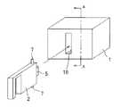
また、図8に示すように、機器本体(2)の内側に、PET(ポリエチレンテレフタレート)等から構成された絶縁部材(8)を設けて、静電気がクレードル(1)に流れることを防ぐ構成も提案されている。When the device body (2) is inserted into the long hole (19), the static eliminating brush (7) is pushed into the long hole (19) while being in contact with the guide rail (70). As the static eliminating brush (7) advances while contacting the guide rail (70), the static electricity charged in the device body (2) is gradually discharged. When the device body (2) is completely inserted, the device body (2) and the cradle (1) are electrically insulated with a sufficient space, except for the connector (5) and the socket (55). This prevents the electronic elements in the cradle (1) from being damaged by static electricity.
In addition, as shown in FIG. 8, an insulating member (8) made of PET (polyethylene terephthalate) or the like is provided inside the device body (2) to prevent static electricity from flowing into the cradle (1). Proposed.
小型の電子機器にあっては、機器本体(2)とクレードル(1)との間に絶縁用の十分な空間を設けたり、除電ブラシ(7)を設けるスペースが無い場合がある。また、機器本体(2)が小型であるから、機器本体(2)の内側に絶縁部材(8)を設けることができない場合もある。
本発明の目的は、機器本体又はクレードルに、除電ブラシや絶縁部材を設けるスペースが無い場合でも、効果的に静電気を放電することにある。In a small electronic device, there may be no sufficient space for insulation between the device main body (2) and the cradle (1) or there is no space for disposing the charge eliminating brush (7). Moreover, since the apparatus main body (2) is small, the insulating member (8) may not be provided inside the apparatus main body (2).
An object of the present invention is to effectively discharge static electricity even when there is no space for providing a static eliminating brush or an insulating member in the apparatus main body or the cradle.
クレードル(1)は、電子機器の機器本体(2)が着脱自在に載置される載置面(11)と、該載置面(11)の内側にて載置面(11)とは放電ギャップHだけ離れた第1の導電性部材(3)又は回路基板(30)を設けている。
第1の導電性部材(3)又は回路基板(30)は、載置面(11)に当接した機器本体(2)上の第2の導電性部材(4)に帯電した静電気を放電ギャップHを介して放電させる。The cradle (1) includes a mounting surface (11) on which a device main body (2) of an electronic device is detachably mounted, and a mounting surface (11) inside the mounting surface (11) is discharged. A first conductive member (3) or a circuit board (30) separated by a gap H is provided.
The first conductive member (3) or the circuit board (30) discharges static electricity charged in the second conductive member (4) on the device body (2) in contact with the mounting surface (11) to the discharge gap. Discharge through H.
本発明に於いては、クレードル(1)の第1の導電性部材(3)と、機器本体(2)の第2の導電性部材(4)との間に放電ギャップHを形成していることにより、静電気を放電できる。これにより、静電気によるクレードル(1)又は機器本体(2)内の電子素子の破損が防止でき、又はノイズ低減が図れる。
更に、クレードル(1)の第1の導電性部材(3)と、機器本体(2)との間に、放電ギャップHを形成していることにより、機器本体(2)がクレードル(1)に繰り返し着脱される場合にあっても、第1の導電性部材(3)によって機器本体(2)に傷が付き、又は機器本体(2)が破損する虞れを防止できる。
また、回路基板(30)上に第1の導電性部材(3)を設けることにより静電対策としているので、クレードル(1)を小型化できる。即ち、従来のように、機器本体(2)又はクレードル(1)に、除電ブラシや絶縁部材を設けるスペースが無い場合でも、効果的に静電気を放電することができる。In the present invention, a discharge gap H is formed between the first conductive member (3) of the cradle (1) and the second conductive member (4) of the device body (2). Therefore, static electricity can be discharged. Thereby, damage to the electronic element in the cradle (1) or the device main body (2) due to static electricity can be prevented, or noise can be reduced.
Further, since the discharge gap H is formed between the first conductive member (3) of the cradle (1) and the device main body (2), the device main body (2) is attached to the cradle (1). Even in the case of repeated attachment and detachment, it is possible to prevent the first conductive member (3) from scratching the equipment body (2) or damaging the equipment body (2).
In addition, since the first conductive member (3) is provided on the circuit board (30) as a countermeasure against static electricity, the cradle (1) can be reduced in size. That is, static electricity can be effectively discharged even when the device main body (2) or the cradle (1) does not have a space for providing a static eliminating brush or an insulating member as in the prior art.
(第1実施例)
以下、本発明の一実施例を図を用いて、詳述する。
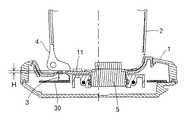
図1は、本例に於ける電子機器の機器本体(2)とクレードル(1)の斜視図であり、図2は図1のクレードル(1)の分解斜視図である。本例にあっては、電子機器としてデジタルカメラを示すが、これに限定されず、PDA、携帯音楽プレーヤ等であってもよい。機器本体(2)はクレードル(1)に載置されて接続され、充電等がされる。クレードル(1)の側面には、電源ケーブル(6)と画像信号用ケーブル(60)(61)が接続される。
クレードル(1)は上面に機器本体(2)の下端部外面に接する4つの爪片(10)(10)(10)(10)を具え、該爪片(10)(10)(10)(10)の内側は機器本体(2)の下面が載る載置面(11)を構成する。該載置面(11)内に、小孔(12)と大孔(13)を開設している。クレードル(1)の内部、即ち載置面(11)の下方には回路基板(30)が配備され、該回路基板(30)上に機器本体(2)と着脱自在に嵌合するコネクタ(5)と、金属製の第1の導電性部材(3)と、前記ケーブル(6)(60)(61)用のソケット(55)(55)(55)が搭載されている。第1の導電性部材(3)は回路基板(30)のグラウンド面に電気的に繋がる。第1の導電性部材(3)の先端部が小孔(12)の内側に対向し、コネクタ(5)が大孔(13)から突出する。第1の導電性部材(3)は小孔(12)から僅かに見える程度の大きさであり、クレードル(1)の見映えを損なわない。(First embodiment)
Hereinafter, an embodiment of the present invention will be described in detail with reference to the drawings.
FIG. 1 is a perspective view of an apparatus main body (2) and a cradle (1) of an electronic apparatus in this example, and FIG. 2 is an exploded perspective view of the cradle (1) of FIG. In this example, a digital camera is shown as an electronic device. However, the present invention is not limited to this, and a PDA, a portable music player, or the like may be used. The device body (2) is placed on and connected to the cradle (1) and charged. A power cable (6) and image signal cables (60) and (61) are connected to the side surface of the cradle (1).
The cradle (1) has four claw pieces (10) (10) (10) (10) in contact with the outer surface of the lower end of the device body (2) on the upper surface, and the claw pieces (10) (10) (10) ( The inner side of 10) constitutes a mounting surface (11) on which the lower surface of the device body (2) is placed. A small hole (12) and a large hole (13) are opened in the mounting surface (11). A circuit board (30) is disposed inside the cradle (1), that is, below the mounting surface (11), and a connector (5) that is detachably fitted to the device body (2) on the circuit board (30). ), A metal first conductive member (3), and sockets (55) (55) (55) for the cables (6) (60) (61). The first conductive member (3) is electrically connected to the ground surface of the circuit board (30). The tip of the first conductive member (3) faces the inside of the small hole (12), and the connector (5) protrudes from the large hole (13). The first conductive member (3) has a size that is slightly visible from the small hole (12), and does not impair the appearance of the cradle (1).
図3は、機器本体(2)とクレードル(1)の接続箇所を、図1のB−B線を含む面にて破断し、矢視した断面図である。機器本体(2)はその外観、具体的には底面部に金属から成る第2の導電性部材(4)を設け、該第2の導電性部材(4)がクレードル(1)の載置面(11)に載る。クレードル(1)の第1の導電性部材(3)と載置面(11)との間には、上下隙間である放電ギャップHが形成されている。クレードル(1)の小孔(12)は、第2の導電性部材(4)の上端部からコネクタ(5)に至るまでの静電気の流路上に形成されるが、この理由及び静電気の放電動作を以下に示す。 FIG. 3 is a cross-sectional view of the connection portion between the device main body (2) and the cradle (1), taken along the line BB of FIG. The device main body (2) is provided with a second conductive member (4) made of metal on its exterior, specifically on the bottom surface, and the second conductive member (4) is a mounting surface for the cradle (1). (11) A discharge gap H that is a vertical gap is formed between the first conductive member (3) of the cradle (1) and the placement surface (11). The small hole (12) of the cradle (1) is formed on the static electricity flow path from the upper end of the second conductive member (4) to the connector (5). Is shown below.
使用者が機器本体(2)を把持することにより、機器本体(2)が静電気を帯びることがある。かかる静電気は第2の導電性部材(4)の上端部から、第2の導電性部材(4)を下向きに流れて、コネクタ(5)に向かう。しかし、第1の導電性部材(3)が放電ギャップHだけ離れて、第2の導電性部材(4)に対向しているから、静電気は第1の導電性部材(3)に向かって流れ放電する。即ち、第1の導電性部材(3)は静電気の逃げ場所であり、放電ギャップHの空気抵抗により静電気の電圧を減圧することができる。また、放電された静電気は、クレードル(1)内の電子素子の破損や誤動作が生じない程度の電圧に下がり、回路基板(30)のグラウンドに落ちる。即ち、放電ギャップHが、第2の導電性部材(4)の上端部からコネクタ(5)に至るまでの静電気の流路上に形成されているから、静電気がコネクタ(5)に至るまでに放電され、コネクタ(5)には流れない。これにより、コネクタ(5)に繋がった電子素子が静電気によって損傷する虞れが低くなり、また、ケーブル(6)(60)(61)へのノイズも低減される。
更に、第1の導電性部材(3)は載置面(11)よりも、クレードル(1)の内部である奥側に位置しているから、機器本体(2)がクレードル(1)に繰り返し着脱される場合にあっても、第1の導電性部材(3)によって機器本体(2)に傷が付き、又は機器本体(2)が破損する虞れを防止できる。When the user grips the device main body (2), the device main body (2) may be charged with static electricity. Such static electricity flows downward from the upper end of the second conductive member (4) through the second conductive member (4) toward the connector (5). However, since the first conductive member (3) is separated by the discharge gap H and faces the second conductive member (4), static electricity flows toward the first conductive member (3). Discharge. That is, the first conductive member (3) is a place where static electricity escapes, and the static electricity voltage can be reduced by the air resistance of the discharge gap H. The discharged static electricity is lowered to a voltage that does not cause damage or malfunction of the electronic elements in the cradle (1), and falls to the ground of the circuit board (30). That is, since the discharge gap H is formed on the static electricity flow path from the upper end of the second conductive member (4) to the connector (5), the static electricity is discharged before reaching the connector (5). And does not flow to the connector (5). Thereby, the possibility that the electronic element connected to the connector (5) is damaged by static electricity is reduced, and noise to the cables (6), (60), (61) is also reduced.
Furthermore, since the first conductive member (3) is located behind the placement surface (11), which is inside the cradle (1), the device body (2) is repeatedly placed on the cradle (1). Even in the case of being attached and detached, it is possible to prevent the first conductive member (3) from scratching the equipment body (2) or damaging the equipment body (2).
(第2実施例)
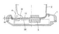
図4は、別の実施例に於けるクレードル(1)の断面図である。これは、回路基板(30)のグラウンド面の一部を、上向きに延びた突起(31)として、該突起(31)の先端部と機器本体(2)の第2の導電性部材(4)との間に、放電ギャップHを形成している。該放電ギャップHにより、第2の導電性部材(4)に帯電した静電気が回路基板(30)のグラウンド面に放電される。(Second embodiment)
FIG. 4 is a cross-sectional view of the cradle (1) in another embodiment. This is because part of the ground surface of the circuit board (30) is formed as a protrusion (31) extending upward, and the tip of the protrusion (31) and the second conductive member (4) of the device body (2). Between the two, a discharge gap H is formed. Due to the discharge gap H, the static electricity charged in the second conductive member (4) is discharged to the ground surface of the circuit board (30).
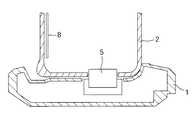
(第3実施例)
図5は、別の実施例に於けるクレードル(1)の断面図である。これは、コネクタ(5)に第1の導電性部材(3)を挿入し、該第1の導電性部材(3)の先端部と、機器本体(2)の第2の導電性部材(4)との間に、放電ギャップHを形成している。該放電ギャップHにより、第2の導電性部材(4)に帯電した静電気が回路基板(30)のグラウンド面に放電される。(Third embodiment)
FIG. 5 is a cross-sectional view of the cradle (1) in another embodiment. This is because the first conductive member (3) is inserted into the connector (5), the tip of the first conductive member (3), and the second conductive member (4) of the device body (2). ), A discharge gap H is formed. Due to the discharge gap H, the static electricity charged in the second conductive member (4) is discharged to the ground surface of the circuit board (30).
(本例の効果)
本例に於いては、クレードル(1)の第1の導電性部材(3)と、機器本体(2)の第2の導電性部材(4)との間に放電ギャップHを形成していることにより、静電気を放電できる。これにより、静電気によるクレードル(1)又は機器本体(2)内の電子素子の破損やケーブル(6)(60)(61)へのノイズ低減が図れる。
更に、クレードル(1)の第1の導電性部材(3)と、機器本体(2)との間に、放電ギャップHを形成していることにより、機器本体(2)がクレードル(1)に繰り返し着脱される場合にあっても、第1の導電性部材(3)によって機器本体(2)に傷が付き、又は機器本体(2)が破損する虞れを防止できる。
また、第1の導電性部材(3)は小孔(12)の内側にあり目立たないから、クレードル(1)の見映えを損なわない。また、回路基板(30)上に第1の導電性部材(3)を設けることにより静電対策としているので、クレードル(1)を小型化できる。即ち、従来のように、機器本体(2)又はクレードル(1)に、除電ブラシや絶縁部材を設けるスペースが無い場合でも、効果的に静電気を放電することができる。(Effect of this example)
In this example, a discharge gap H is formed between the first conductive member (3) of the cradle (1) and the second conductive member (4) of the device body (2). Therefore, static electricity can be discharged. Thereby, damage to the electronic elements in the cradle (1) or the device main body (2) due to static electricity and noise reduction to the cables (6), (60), (61) can be achieved.
Further, since the discharge gap H is formed between the first conductive member (3) of the cradle (1) and the device main body (2), the device main body (2) is attached to the cradle (1). Even in the case of repeated attachment and detachment, it is possible to prevent the first conductive member (3) from scratching the equipment body (2) or damaging the equipment body (2).
Further, since the first conductive member (3) is not conspicuous inside the small hole (12), the appearance of the cradle (1) is not impaired. In addition, since the first conductive member (3) is provided on the circuit board (30) as a countermeasure against static electricity, the cradle (1) can be reduced in size. That is, static electricity can be effectively discharged even when the device main body (2) or the cradle (1) does not have a space for providing a static eliminating brush or an insulating member as in the prior art.
上記実施例の説明は、本発明を説明するためのものであって、特許請求の範囲に記載の発明を限定し、或は範囲を減縮する様に解すべきではない。又、本発明の各部構成は上記実施例に限らず、特許請求の範囲に記載の技術的範囲内で種々の変形が可能であることは勿論である。 The above description of the embodiments is for explaining the present invention, and should not be construed as limiting the invention described in the claims or reducing the scope thereof. In addition, the configuration of each part of the present invention is not limited to the above embodiment, and various modifications can be made within the technical scope described in the claims.
(1) クレードル
(2) 機器本体
(3) 第1の導電性部材
(4) 第2の導電性部材
(5) コネクタ
(11) 載置面
(30) 回路基板(1) Cradle
(2) Device body
(3) First conductive member
(4) Second conductive member
(5) Connector
(11) Mounting surface
(30) Circuit board
Claims (2)
Translated fromJapanese第1の導電性部材(3)又は回路基板(30)は、載置面(11)に当接した機器本体(2)上の第2の導電性部材(4)に帯電した静電気を放電ギャップHを介して放電させることを特徴とするクレードル。The mounting surface (11) on which the device main body (2) of the electronic device is detachably mounted and the mounting surface (11) inside the mounting surface (11) are separated by a discharge gap H. 1 conductive member (3) or circuit board (30) is provided,
The first conductive member (3) or the circuit board (30) discharges static electricity charged in the second conductive member (4) on the device body (2) in contact with the mounting surface (11) to the discharge gap. A cradle characterized by discharging through H.
Priority Applications (1)
| Application Number | Priority Date | Filing Date | Title |
|---|---|---|---|
| JP2006018436AJP2007200731A (en) | 2006-01-27 | 2006-01-27 | Cradle equipped with electronic equipment freely |
Applications Claiming Priority (1)
| Application Number | Priority Date | Filing Date | Title |
|---|---|---|---|
| JP2006018436AJP2007200731A (en) | 2006-01-27 | 2006-01-27 | Cradle equipped with electronic equipment freely |
Publications (1)
| Publication Number | Publication Date |
|---|---|
| JP2007200731Atrue JP2007200731A (en) | 2007-08-09 |
Family
ID=38455126
Family Applications (1)
| Application Number | Title | Priority Date | Filing Date |
|---|---|---|---|
| JP2006018436AWithdrawnJP2007200731A (en) | 2006-01-27 | 2006-01-27 | Cradle equipped with electronic equipment freely |
Country Status (1)
| Country | Link |
|---|---|
| JP (1) | JP2007200731A (en) |
Cited By (2)
| Publication number | Priority date | Publication date | Assignee | Title |
|---|---|---|---|---|
| JP2015215983A (en)* | 2014-05-08 | 2015-12-03 | 株式会社マキタ | Powered work machine |
| WO2020129848A1 (en)* | 2018-12-19 | 2020-06-25 | 株式会社ソニー・インタラクティブエンタテインメント | Charging device, control device, and apparatus system |
- 2006
- 2006-01-27JPJP2006018436Apatent/JP2007200731A/ennot_activeWithdrawn
Cited By (6)
| Publication number | Priority date | Publication date | Assignee | Title |
|---|---|---|---|---|
| JP2015215983A (en)* | 2014-05-08 | 2015-12-03 | 株式会社マキタ | Powered work machine |
| WO2020129848A1 (en)* | 2018-12-19 | 2020-06-25 | 株式会社ソニー・インタラクティブエンタテインメント | Charging device, control device, and apparatus system |
| CN113195069A (en)* | 2018-12-19 | 2021-07-30 | 索尼互动娱乐股份有限公司 | Charging device, control device and equipment system |
| JPWO2020129848A1 (en)* | 2018-12-19 | 2021-10-21 | 株式会社ソニー・インタラクティブエンタテインメント | Charging device, control device and equipment system |
| JP7049484B2 (en) | 2018-12-19 | 2022-04-06 | 株式会社ソニー・インタラクティブエンタテインメント | Charging device, control device and equipment system |
| CN113195069B (en)* | 2018-12-19 | 2023-02-28 | 索尼互动娱乐股份有限公司 | Charging device, control device and equipment system |
Similar Documents
| Publication | Publication Date | Title |
|---|---|---|
| CN102074824B (en) | Magnetic connector with integral housing | |
| US8215983B2 (en) | Electronic device | |
| US7453692B2 (en) | Computer device with a modular transmission interface, the modular transmission interface, and an adaptor board | |
| US7621753B1 (en) | Magnetic power socket and plug and combination thereof | |
| US7813113B2 (en) | Expansion interface module having protection circuit | |
| JP7082678B2 (en) | Data cable device with cable battery | |
| US9060441B2 (en) | Electronic device and power supply positioining apparatus thereof | |
| CN101650582A (en) | Electronic equipment and interface protective cover thereof | |
| JP2015511380A (en) | Connector receptacle with side ground contact | |
| US20140146492A1 (en) | Power supply unit | |
| JP2007200731A (en) | Cradle equipped with electronic equipment freely | |
| CN106164782A (en) | Electrical equipment | |
| US20090190297A1 (en) | Motherboard expansion device | |
| CN102468568A (en) | Connector assembly and accommodating device thereof | |
| JP5268032B2 (en) | Unit device | |
| US7192314B1 (en) | Power connector assembly device | |
| CN107565647B (en) | Portable mobile power supply | |
| US9952641B1 (en) | Electronic device | |
| TW201707517A (en) | Electro-static discharge protection structure and electronic device | |
| CN104103919A (en) | Electric connector assembly | |
| CN102623836A (en) | audio connector | |
| CN106785652A (en) | A kind of protection socket | |
| US20130316597A1 (en) | Power connector and center terminal | |
| JP4978164B2 (en) | Insulating structure and electronic device using the same | |
| CN109375719A (en) | A kind of computer box with sound equipment |
Legal Events
| Date | Code | Title | Description |
|---|---|---|---|
| A300 | Application deemed to be withdrawn because no request for examination was validly filed | Free format text:JAPANESE INTERMEDIATE CODE: A300 Effective date:20090407 |