JP2007200192A - Tire management system - Google Patents
Tire management systemDownload PDFInfo
- Publication number
- JP2007200192A JP2007200192AJP2006020514AJP2006020514AJP2007200192AJP 2007200192 AJP2007200192 AJP 2007200192AJP 2006020514 AJP2006020514 AJP 2006020514AJP 2006020514 AJP2006020514 AJP 2006020514AJP 2007200192 AJP2007200192 AJP 2007200192A
- Authority
- JP
- Japan
- Prior art keywords
- sensor module
- request signal
- module
- data request
- tire
- Prior art date
- Legal status (The legal status is an assumption and is not a legal conclusion. Google has not performed a legal analysis and makes no representation as to the accuracy of the status listed.)
- Withdrawn
Links
- 238000005259measurementMethods0.000claimsabstractdescription43
- 238000004891communicationMethods0.000claimsabstractdescription30
- 230000005540biological transmissionEffects0.000description25
- 238000000034methodMethods0.000description8
- 238000010586diagramMethods0.000description6
- 238000001228spectrumMethods0.000description3
- 238000001514detection methodMethods0.000description2
- 238000005065miningMethods0.000description2
- 230000005856abnormalityEffects0.000description1
- 230000008054signal transmissionEffects0.000description1
Images


Classifications
- B—PERFORMING OPERATIONS; TRANSPORTING
- B60—VEHICLES IN GENERAL
- B60C—VEHICLE TYRES; TYRE INFLATION; TYRE CHANGING; CONNECTING VALVES TO INFLATABLE ELASTIC BODIES IN GENERAL; DEVICES OR ARRANGEMENTS RELATED TO TYRES
- B60C23/00—Devices for measuring, signalling, controlling, or distributing tyre pressure or temperature, specially adapted for mounting on vehicles; Arrangement of tyre inflating devices on vehicles, e.g. of pumps or of tanks; Tyre cooling arrangements
- B60C23/02—Signalling devices actuated by tyre pressure
- B60C23/04—Signalling devices actuated by tyre pressure mounted on the wheel or tyre
- B60C23/0408—Signalling devices actuated by tyre pressure mounted on the wheel or tyre transmitting the signals by non-mechanical means from the wheel or tyre to a vehicle body mounted receiver
- B60C23/0422—Signalling devices actuated by tyre pressure mounted on the wheel or tyre transmitting the signals by non-mechanical means from the wheel or tyre to a vehicle body mounted receiver characterised by the type of signal transmission means
- B60C23/0433—Radio signals
- B60C23/0435—Vehicle body mounted circuits, e.g. transceiver or antenna fixed to central console, door, roof, mirror or fender
- B60C23/0438—Vehicle body mounted circuits, e.g. transceiver or antenna fixed to central console, door, roof, mirror or fender comprising signal transmission means, e.g. for a bidirectional communication with a corresponding wheel mounted receiver
- B60C23/0442—Vehicle body mounted circuits, e.g. transceiver or antenna fixed to central console, door, roof, mirror or fender comprising signal transmission means, e.g. for a bidirectional communication with a corresponding wheel mounted receiver the transmitted signal comprises further information, e.g. instruction codes, sensor characteristics or identification data
- B—PERFORMING OPERATIONS; TRANSPORTING
- B60—VEHICLES IN GENERAL
- B60C—VEHICLE TYRES; TYRE INFLATION; TYRE CHANGING; CONNECTING VALVES TO INFLATABLE ELASTIC BODIES IN GENERAL; DEVICES OR ARRANGEMENTS RELATED TO TYRES
- B60C23/00—Devices for measuring, signalling, controlling, or distributing tyre pressure or temperature, specially adapted for mounting on vehicles; Arrangement of tyre inflating devices on vehicles, e.g. of pumps or of tanks; Tyre cooling arrangements
- B60C23/02—Signalling devices actuated by tyre pressure
- B60C23/04—Signalling devices actuated by tyre pressure mounted on the wheel or tyre
- B60C23/0408—Signalling devices actuated by tyre pressure mounted on the wheel or tyre transmitting the signals by non-mechanical means from the wheel or tyre to a vehicle body mounted receiver
- B60C23/0422—Signalling devices actuated by tyre pressure mounted on the wheel or tyre transmitting the signals by non-mechanical means from the wheel or tyre to a vehicle body mounted receiver characterised by the type of signal transmission means
- B60C23/0433—Radio signals
- B60C23/0447—Wheel or tyre mounted circuits
- B60C23/0455—Transmission control of wireless signals
- B60C23/0462—Structure of transmission protocol
Landscapes
- Engineering & Computer Science (AREA)
- Mechanical Engineering (AREA)
- Computer Networks & Wireless Communication (AREA)
- Arrangements For Transmission Of Measured Signals (AREA)
- Measuring Fluid Pressure (AREA)
Abstract
Translated fromJapaneseDescription
Translated fromJapanese本発明は、車両に装着されたタイヤの内側に取り付けられ、タイヤ内圧を含むタイヤ状態量を測定するセンサモジュールと、車体側に取り付けられ、センサモジュールから送信された測定データを受信する受信モジュールとを具えたタイヤ管理システムの改良に関するものである。 The present invention includes a sensor module that is attached to the inside of a tire mounted on a vehicle and that measures a tire state quantity including tire internal pressure, and a reception module that is attached to a vehicle body and receives measurement data transmitted from the sensor module. Is related to the improvement of the tire management system.
鉱山用車両等の運行中のタイヤの管理を行うため、タイヤの内圧や温度等のタイヤ状態量を測定するセンサモジュールをタイヤの内部に取り付けて、このセンサモジュールからの測定データを車体側の受信モジュールで受信し、受信したデータを、複数の車両を管理する車両運行管理センターに送信するよう構成されたタイヤ管理システムを車両に搭載することが提案されていて、この提案は、各車両のタイヤ管理システムのデータに基づき、もし車両が故障を起こす可能性があると判断される場合には、車両運行管理センターから運転者に必要な処置を指示することにより危険な状況を未然に防止することを目的とするものである(例えば、特許文献1)。 In order to manage tires during operation of mining vehicles, etc., a sensor module that measures tire state quantities such as tire internal pressure and temperature is installed inside the tire, and measurement data from this sensor module is received on the vehicle body side. It has been proposed that a vehicle be equipped with a tire management system configured to receive the module and transmit the received data to a vehicle operation management center that manages a plurality of vehicles. Based on the data of the management system, if it is determined that there is a possibility that the vehicle will break down, the dangerous situation should be prevented by instructing the driver the necessary measures from the vehicle operation management center. (For example, Patent Document 1).
このようなタイヤ管理システムでは、各受信モジュールから、所定周期で、対応するセンサモジュールにデータ要求信号が送信され、センサモジュールは、データ要求信号を受信したタイミングにあわせて、タイヤ状態量の測定を行い、測定結果を受信モジュールに送信するよう構成されており、受信モジュールは、このようにして、センサモジュールから測定データを取得することができる。
ところで、受信モジュールとセンサモジュールとの間の信号の送受信のために、一定の周波数帯が一般に開放されているが、周波数帯のうち特定のチャンネルについては、鉱山によっては、その鉱山特有の事情によって使用できないことがある。例えば、妨害電波のあるチャンネルとか、他の機器が使用しているチャンネルについては使用できない。そのため、上述したタイヤ管理システムでは、複数のチャンネルを用意しておいて、通信に失敗したら異なるチャンネルに切り替える機能も有している。しかしながら、初めからこのような妨害電波等のあるチャンネルを受信モジュールが選択できないようにしておけば、受信確率の向上が期待できる。そのため、予めスペクトルアナライザを用いて妨害電波等のあるチャンネルを検出することも行われているが、スペクトルアナライザを用いる方法では、時間と手間がかかるという問題があった。 By the way, a certain frequency band is generally open for the transmission and reception of signals between the receiving module and the sensor module, but a specific channel in the frequency band may depend on the situation specific to the mine depending on the mine. It may not be usable. For example, it cannot be used for channels with jamming waves or channels used by other devices. Therefore, the tire management system described above has a function of preparing a plurality of channels and switching to a different channel when communication fails. However, if the receiving module cannot select such a channel with jamming waves from the beginning, an improvement in reception probability can be expected. For this reason, a spectrum analyzer is used in advance to detect a channel such as a jamming radio wave. However, the method using the spectrum analyzer has a problem that it takes time and effort.
本発明は、このような問題点に鑑みてなされたものであり、その目的は、スペクトルアナライザを用いることなく妨害電波等のあるチャンネルを検出し、受信モジュールがセンサモジュールにデータ要求信号を送信する際に、妨害電波等のあるチャンネルの周波数を選択できないようにし、センサモジュールにとって受信確率の高い周波数を選択できるようにすることによって、受信モジュールが速やかにセンサモジュールと信号の送受信を行えるタイヤ管理システムを提供することにある。 The present invention has been made in view of such problems, and an object of the present invention is to detect a channel having a jamming wave or the like without using a spectrum analyzer, and the receiving module transmits a data request signal to the sensor module. In this case, the frequency of a channel with a jamming wave or the like cannot be selected, and a frequency with a high reception probability for the sensor module can be selected so that the receiving module can quickly transmit and receive signals to and from the sensor module. Is to provide.
上記目的を達成するため本発明は、車両に装着されたタイヤの内側に取り付けられ、タイヤ状態量を測定しこの測定データを車体側に送信するセンサモジュールと、車体側に設けられ、所定の周期で、センサモジュールに前記測定データを要求するデータ要求信号を送信するとともに、センサモジュールから送信された測定データを取得する受信モジュールとを具えたタイヤ管理システムにおいて、前記受信モジュールが、前記センサモジュールとの通信に所定回数失敗した通信チャンネル以外の通信チャンネルの周波数で、前記センサモジュールにデータ要求信号を送信するように構成されていることを特徴とする。 In order to achieve the above object, the present invention provides a sensor module that is mounted on the inside of a tire mounted on a vehicle, measures a tire state quantity, and transmits the measurement data to the vehicle body side, and is provided on the vehicle body side, and has a predetermined cycle. Then, in the tire management system comprising a receiving module for transmitting the data request signal for requesting the measurement data to the sensor module and acquiring the measurement data transmitted from the sensor module, the receiving module includes the sensor module and A data request signal is transmitted to the sensor module at a frequency of a communication channel other than a communication channel that has failed a predetermined number of times.
前記所定回数は、確実に使用できないチャンネルであると判定できる回数であることが好ましい。。 The predetermined number of times is preferably the number of times that it can be determined that the channel cannot be reliably used. .
また、本発明は、車両に装着されたタイヤの内側に取り付けられ、タイヤ状態量を測定しこの測定データを車体側に送信するセンサモジュールと、車体側に設けられ、所定の周期で、センサモジュールに前記測定データを要求するデータ要求信号を送信するとともに、センサモジュールから送信された測定データを取得する受信モジュールとを具えたタイヤ管理システムにおいて、前記受信モジュールが、通信チャンネルでの通信失敗回数が上位N(Nは1以上の自然数)番目までの通信チャンネル以外の通信チャンネルの周波数で、前記センサモジュールにデータ要求信号を送信するように構成されていることを特徴とする。 The present invention also includes a sensor module that is attached to the inside of a tire mounted on a vehicle, measures a tire state quantity, and transmits the measurement data to the vehicle body side. The sensor module is provided on the vehicle body side at a predetermined cycle. In the tire management system including a reception module for acquiring the measurement data transmitted from the sensor module and transmitting a data request signal for requesting the measurement data, the reception module has a communication channel number of communication failures. A data request signal is transmitted to the sensor module at a frequency of a communication channel other than the upper N (N is a natural number equal to or greater than 1) communication channel.
本発明のタイヤ管理システムは、受信モジュールが、センサモジュールとの通信に所定回数失敗した通信チャンネルや、通信チャンネルでの通信失敗回数が上位N(Nは1以上の自然数)番目までの通信チャンネルを選択できないようにして、センサモジュールにとって受信確率の高いチャンネルの周波数でセンサモジュールにデータ要求信号を送信するようにしたので、受信モジュールが速やかにセンサモジュールと信号の送受信を行うことができる。 In the tire management system according to the present invention, the receiving module is configured to select a communication channel in which communication with the sensor module has failed a predetermined number of times, or a communication channel having the highest N (N is a natural number equal to or greater than 1) communication channel. Since the data request signal is transmitted to the sensor module at a frequency of a channel having a high reception probability for the sensor module so that the selection is not possible, the reception module can promptly transmit and receive signals to and from the sensor module.
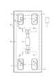
次に、本発明の実施形態について図面に基づいて説明する。図1は、本発明のタイヤ管理システムの構成を示す概略配置図である。センサモジュール3は、車両6に装着されたそれぞれのタイヤ4に取り付けられる。 Next, embodiments of the present invention will be described with reference to the drawings. FIG. 1 is a schematic layout diagram showing a configuration of a tire management system of the present invention. The
センサモジュール3は、タイヤ4の内面に焼き付けて取り付けられ、走行中のタイヤが荷重下で変形してもタイヤから隔離したり壊れたりしないよう設けられている。また、センサモジュール3は、タイヤ内圧等を検知する検知手段、受信モジュール1との送受信を司るアンテナ3aやトランスミッタ、および、これらを制御する制御手段を具えて構成される。検知手段としては、タイヤ内圧の他にタイヤ温度を検知するものも含むことができる。なお、センサモジュール3は、タイヤ内側空間においてホイールに取り付けたり、タイヤ内側空間に別途の手段で保持したりすることも可能である。 The
タイヤ管理システム10は、車両6のそれぞれのタイヤ4内に取り付けられたセンサモジュール3と、センサモジュール3からの温度や圧力のデータを含む無線信号を受信するアンテナ1aを備えてアンテナ1aから温度や圧力のデータを取得する受信モジュール1と、受信モジュール1にセンサモジュール3からのデータ取得を指令する中央制御モジュール5と、中央制御モジュール5から無線で送信される信号を受信してタイヤの走行状況を監視する車両運行管理センター7から構成されている。なお、受信モジュール3は、中央制御モジュールの内部に配置するようにすることも可能である。 The
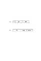
図2(a)は、受信モジュール1がセンサモジュール3に対して、測定データの送信を要求するデータ要求信号Dの送信タイミングを示すタイミングチャートである。データ要求信号Dの送信周期は、周期Tとして定めることができ、データ要求信号Dの送信処理は、周期Tの時間間隔で繰り返し行われる。 FIG. 2A is a timing chart showing the transmission timing of the data request signal D for requesting the
図2(b)は、センサモジュール3が測定データ信号を送信するタイミングを示すタイミングチャートである。センサモジュール3は、受信モジュール1から周期Tの時間間隔で送られてくるデータ要求信号Dを検知した場合、タイヤの内圧等のタイヤ状態量を測定する測定処理を行い、測定結果としての測定データ信号Aをアンテナ3a,1aを介して受信モジュール1に送信する送信処理を行う。 FIG. 2B is a timing chart showing the timing at which the
図3は、図2(a)におけるデータ要求信号Dを拡大して示すタイミングチャートである。受信モジュール1が送信するデータ要求信号Dは、所定の周期で送信されるデータ要求信号Eが、図3に示すように、複数個集まったものであり、受信モジュール1は、周波数F1で送信したデータ要求信号Eに対して、所定の時間内にセンサモジュール3からデータ送信がない場合には、再びデータ要求信号Eを送信し、センサモジュールからのデータ送信を待つ。更にデータ要求信号Eに定められた送信回数の上限値m(図3ではm=4)に達するまでデータ要求信号Eを繰り返して送信してもセンサモジュール3からデータ送信がない場合には、異なる周波数F2のデータ要求信号Eを送信し、センサモジュールからのデータ送信を待つ。このデータ要求信号Eの送信動作は、センサモジュール3からのデータ送信が確認されると停止される。したがって、データ要求信号Eの個数はセンサモジュールからのデータ送信の有無によって変化する。FIG. 3 is an enlarged timing chart showing the data request signal D in FIG. The data request signal D transmitted by the receiving
図4は、受信モジュール1およびセンサモジュール3が、それぞれデータの送信に使用する周波数帯域を示す概念図であり、横軸は周波数を示す。受信モジュール1およびセンサモジュール3が送信に使用する周波数帯域は、図示の所定周波数領域ΔFを互いに重ならないよう分割して予め定められる。図示の例においては、RMで示した合計53個のチャンネルは、受信モジュール1からセンサモジュール3へのデータ要求信号送信用に割り当てられ、SMで示した合計14個のチャンネルは、センサモジュール3から受信モジュール1への測定データ信号送信用に割り当てられる。 FIG. 4 is a conceptual diagram showing frequency bands used by the
センサモジュール3が測定データ信号の送信に使用するチャンネルの識別符号は、受信モジュールが送信するデータ要求信号の一部としてセンサモジュール3に送信され、この信号を受けたセンサモジュールは、そこに指定されているチャンネルの周波数を用いて測定データ信号を送信することになる。 The identification code of the channel used by the
図5は、データ構造を示す図であり、図5(a)は、受信モジュールが送信するデータ要求信号を示し、このデータ要求信号は、データ送信要求を表わす指令CMD、送信対象となるセンサモジュール3の自己識別符号IDのほか、上述した通り、センサモジュール3が測定データ信号の送信に使用すべきチャンネルを表わす識別符号fよりなっており、一方、図5(b)は、センサモジュール3が送信する測定データ信号の構造を示し、この信号は、測定データDATA、異常フラグOK/NG、および、送信するセンサモジュール3のIDよりなっている。 FIG. 5 is a diagram showing a data structure. FIG. 5A shows a data request signal transmitted by the receiving module. The data request signal includes a command CMD indicating a data transmission request and a sensor module to be transmitted. In addition to the self-
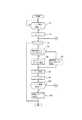
次に、本発明のタイヤ管理システムにおける受信モジュールの動作について詳細に説明する。図6および図7は、受信モジュール1の第1実施例の処理を示すフローチャートである。 Next, the operation of the receiving module in the tire management system of the present invention will be described in detail. 6 and 7 are flowcharts showing the processing of the receiving
ステップs1において、受信モジュール1は、センサモジュール3へ前回データ要求信号を送信した時から周期Tの時間が経過したか否かを判定する。周期Tの時間が経過していない場合は、周期Tになるまで、ステップs1を繰り返す。周期Tになれば、カウンタnを0に設定する(ステップs2)。カウンタnは、ある周波数のデータ要求信号の送信回数を表すカウンタである。 In step s1, the receiving
次に、ステップs3において、データ要求信号の送信回数であるカウンタnが、データ要求信号に定められた送信回数の上限値m以下であるか、mより大きいかを判定する。この場合、カウンタnは1に設定されており、m以下であるので、ステップs4において、使用禁止チャンネルが有るか、無いかを判定する。もし、使用禁止チャンネルが無ければ、データ要求信号の使用周波数を、全てのチャンネルから選択し(ステップs5)、使用禁止チャンネルが有れば、データ要求信号の使用周波数を、使用禁止チャンネル以外から選択する(ステップs6)。 Next, in step s3, it is determined whether the counter n, which is the number of transmissions of the data request signal, is less than or equal to the upper limit m of the number of transmissions defined in the data request signal. In this case, since the counter n is set to 1 and is equal to or less than m, it is determined in step s4 whether or not there is a use-prohibited channel. If there is no use prohibition channel, the use frequency of the data request signal is selected from all channels (step s5). If there is a use prohibition channel, the use frequency of the data request signal is selected from other than the use prohibition channel. (Step s6).
次に、ステップs7において、受信モジュール1は、選択したチャンネルの周波数でデータ要求信号をセンサモジュール3に送信し、ステップs8において、データ要求信号の送信回数を表すカウンタnを1だけ増加させる。 Next, in step s7, the receiving
次に、ステップs9において、受信モジュール1は、センサモジュール3からの測定データの取得に成功したかを判定する。ステップs9において、測定データの取得に成功した場合は、センサモジュール3から取得した測定データを保存する(ステップs14)。 Next, in step s9, the receiving
センサモジュール3からの測定データの取得に失敗した場合は、センサモジュール3が受信モジュール1からデータ要求信号を受信できなかったとして、通信に失敗したデータ要求信号の使用周波数の通信チャンネルのカウンタAxを1だけ増加させる(ステップs10)。カウンタAxは、通信チャンネルでの通信失敗回数を格納するカウンタであり、通信チャンネル毎に設けられる。次に、ステップs11において、カウンタAxがカウンタ上限値B以上であるか、Bより小さいかを判定する。このカウンタ上限値Bは、妨害電波等があるために確実に使用できないチャンネルであると判定できる回数の値である。 If acquisition of the measurement data from the
カウンタAxがカウンタ上限値B以上であれば、次に、ステップs12において、使用禁止チャンネルの設定個数が上限か否かを判断し、使用禁止チャンネルの設定個数が上限でない場合は、ステップs13において、この測定データ取得失敗時のチャンネルを使用禁止チャンネルに設定する。使用禁止チャンネルの設定個数に上限を設けたのは、使用禁止チャンネルを無制限に設定できるようにすると、使用禁止チャンネルの設定個数が、受信モジュールの本来の使用可能なチャンネル数を超えてしまった場合に、受信モジュールが選択できるチャンネルがなくなってしまうからである。したがって、使用禁止チャンネルの設定個数は、本来の使用可能なチャンネル数より小さい値となる。 If the counter Ax is greater than or equal to the counter upper limit value B, then in step s12, it is determined whether or not the set number of use-prohibited channels is the upper limit. If the set number of use-prohibited channels is not the upper limit, in step s13, The channel when measurement data acquisition fails is set as a use-prohibited channel. The upper limit is set for the number of prohibited channels that can be set if the number of prohibited channels exceeds the number of channels that can be used by the receiving module. This is because there are no channels that can be selected by the receiving module. Accordingly, the set number of use-prohibited channels is smaller than the original number of usable channels.
そして、ステップs11において、カウンタAxがBより小さい場合、および、ステップs12において、使用禁止チャンネルの設定個数が上限である場合、および、ステップs13において、使用禁止チャンネルを設定した後は、ステップs3に戻る。 In step s11, if the counter Ax is smaller than B, if the set number of use-prohibited channels is the upper limit in step s12, and after setting the use-prohibited channel in step s13, the process proceeds to step s3. Return.
ステップs3において、カウンタnがm以下であるか、mより大きいかを判定し、m以下であれば、再び、ステップs4において、使用禁止チャンネルが有るか、無いかを判定する。 In step s3, it is determined whether the counter n is equal to or less than m or greater than m. If it is equal to or less than m, it is determined again in step s4 whether there is a use-prohibited channel.
ステップs3において、カウンタnがmより大きい場合、および、ステップs14において、センサモジュール3から測定データの取得に成功し、取得した測定データを保存した場合は、上述した処理ルーチンを終了する。そして、他の受信モジュールに切り替えて、他の受信モジュールとセンサモジュールとの間で改めて上述した処理ルーチンを開始する。 In step s3, when the counter n is larger than m, and in step s14, when the measurement data is successfully acquired from the
次に、受信モジュールの第2実施例の動作について詳細に説明する。図8は、受信モジュールの第2実施例の処理を示すフローチャートである。 Next, the operation of the second embodiment of the receiving module will be described in detail. FIG. 8 is a flowchart showing the process of the second embodiment of the receiving module.
ステップs1において、受信モジュール1は、センサモジュール3へ前回データ要求信号を送信した時から周期Tの時間が経過したか否かを判定する。周期Tの時間が経過していない場合は、周期Tになるまで、ステップs21を繰り返す。周期Tになれば、カウンタnを0に設定する(ステップs22)。カウンタnは、ある周波数のデータ要求信号の送信回数を表すカウンタである。 In step s1, the receiving
次に、ステップs23において、データ要求信号の送信回数であるカウンタnが、データ要求信号に定められた送信回数の上限値m以下であるか、mより大きいかを判定する。この場合、カウンタnは1に設定されており、m以下であるので、ステップs24において、使用禁止チャンネルが有るか、無いかを判定する。もし、使用禁止チャンネルが無ければ、データ要求信号の使用周波数を、全てのチャンネルから選択し(ステップs25)、使用禁止チャンネルが有れば、データ要求信号の使用周波数を、通信チャンネルでの通信失敗回数を格納するカウンタAxの上位N(Nは自然数)番目までのチャンネルを除外して、それ以外のチャンネルから選択する(ステップs26)。 Next, in step s23, it is determined whether the counter n, which is the number of transmissions of the data request signal, is less than or equal to the upper limit m of the number of transmissions determined in the data request signal. In this case, since the counter n is set to 1 and is equal to or less than m, it is determined in step s24 whether there is a use-prohibited channel. If there is no use-prohibited channel, the use frequency of the data request signal is selected from all channels (step s25). If there is a use-prohibited channel, the use frequency of the data request signal is set to the communication channel failure. The channels up to the top N (N is a natural number) of the counter Ax that stores the number of times are excluded and selected from the other channels (step s26).
次に、ステップs27において、受信モジュール1は、選択したチャンネルの周波数でデータ要求信号をセンサモジュール3に送信し、ステップs28において、データ要求信号の送信回数を表すカウンタnを1だけ増加させる。 Next, in step s27, the receiving
次に、ステップs29において、受信モジュール1は、センサモジュール3からの測定データの取得に成功したかを判定する。ステップs29において、測定データの取得に成功した場合は、センサモジュール3から取得した測定データを保存する(ステップs31)。 Next, in step s29, the receiving
センサモジュール3からの測定データの取得に失敗した場合は、ステップs30において、センサモジュール3が受信モジュール1からデータ要求信号を受信できなかったとして、通信に失敗したデータ要求信号の使用周波数の通信チャンネルのカウンタAxを1だけ増加させ、ステップs23に戻る。 If acquisition of measurement data from the
ステップs23において、カウンタnがm以下であるか、mより大きいかを判定し、m以下であれば、再び、ステップs24において、使用禁止チャンネルが有るか、無いかを判定する。 In step s23, it is determined whether the counter n is equal to or less than m or greater than m. If it is equal to or less than m, it is determined again in step s24 whether there is a use-prohibited channel.
ステップs23において、カウンタnがmより大きい場合、および、ステップs31において、センサモジュール3から測定データの取得に成功し、取得した測定データを保存した場合は、上述した処理ルーチンを終了する。そして、他の受信モジュールに切り替えて、他の受信モジュールとセンサモジュールとの間で改めて上述した処理ルーチンを開始する。 In step s23, when the counter n is larger than m, and in step s31, when the measurement data is successfully acquired from the
上述したように本発明のタイヤ管理システムによれば、受信モジュールが、センサモジュールとの通信に所定回数失敗した通信チャンネルや、通信チャンネルでの通信失敗回数が上位N(Nは1以上の自然数)番目までの通信チャンネルを選択できないようにして、センサモジュールにとって受信確率の高いチャンネルの周波数でセンサモジュールにデータ要求信号を送信するようにしたので、受信モジュールが速やかにセンサモジュールと信号の送受信を行うことができる。 As described above, according to the tire management system of the present invention, the receiving module is the communication channel in which communication with the sensor module has failed a predetermined number of times, or the communication channel number of communication failures is the top N (N is a natural number of 1 or more). Since the first communication channel cannot be selected and the data request signal is transmitted to the sensor module at the frequency of the channel having a high reception probability for the sensor module, the receiving module promptly transmits and receives signals to and from the sensor module. be able to.
なお、本発明は、センサモジュールが、受信モジュールに測定データ信号を送信する場合にも適用できるものである。 The present invention can also be applied when the sensor module transmits a measurement data signal to the receiving module.
この発明は、鉱山用車両に用いられるタイヤだけでなく、乗用車を含めたすべての種類のタイヤの状態情報をリアルタイムで測定するシステムに用いることができる。 The present invention can be used not only for tires used for mining vehicles but also for systems that measure in real time the status information of all types of tires including passenger cars.
1 受信モジュール
1a、3a アンテナ
3 センサモジュール
4 タイヤ
5 中央制御モジュール
6 車両
7 車両運行管理センター
10 タイヤ管理システムDESCRIPTION OF
Claims (3)
Translated fromJapanese前記受信モジュールは、前記センサモジュールとの通信に所定回数失敗した通信チャンネル以外の通信チャンネルの周波数で、前記センサモジュールにデータ要求信号を送信するように構成されていることを特徴とするタイヤ管理システム。A sensor module that is attached to the inside of a tire mounted on a vehicle, measures a tire state quantity and transmits the measurement data to the vehicle body side, and is provided on the vehicle body side, and requests the measurement data from the sensor module at a predetermined cycle. In a tire management system comprising a receiving module that transmits a data request signal to be acquired and obtains measurement data transmitted from the sensor module,
The tire management system, wherein the receiving module is configured to transmit a data request signal to the sensor module at a frequency of a communication channel other than a communication channel that has failed to communicate with the sensor module a predetermined number of times. .
前記受信モジュールは、通信チャンネルでの通信失敗回数が上位N(Nは1以上の自然数)番目までの通信チャンネル以外の通信チャンネルの周波数で、前記センサモジュールにデータ要求信号を送信するように構成されていることを特徴とするタイヤ管理システム。A sensor module that is attached to the inside of a tire mounted on a vehicle, measures a tire state quantity and transmits the measurement data to the vehicle body side, and is provided on the vehicle body side, and requests the measurement data from the sensor module at a predetermined cycle. In a tire management system comprising a receiving module that transmits a data request signal to be acquired and obtains measurement data transmitted from the sensor module,
The receiving module is configured to transmit a data request signal to the sensor module at a frequency of a communication channel other than the communication channel up to the top N (N is a natural number of 1 or more) in the communication channel. Tire management system characterized by that.
Priority Applications (4)
| Application Number | Priority Date | Filing Date | Title |
|---|---|---|---|
| JP2006020514AJP2007200192A (en) | 2006-01-30 | 2006-01-30 | Tire management system |
| CA002576351ACA2576351C (en) | 2006-01-30 | 2007-01-26 | Tire management system |
| US11/698,841US7679502B2 (en) | 2006-01-30 | 2007-01-29 | Tire management system |
| AU2007200390AAU2007200390B2 (en) | 2006-01-30 | 2007-01-30 | Tire management system |
Applications Claiming Priority (1)
| Application Number | Priority Date | Filing Date | Title |
|---|---|---|---|
| JP2006020514AJP2007200192A (en) | 2006-01-30 | 2006-01-30 | Tire management system |
Publications (1)
| Publication Number | Publication Date |
|---|---|
| JP2007200192Atrue JP2007200192A (en) | 2007-08-09 |
Family
ID=38326354
Family Applications (1)
| Application Number | Title | Priority Date | Filing Date |
|---|---|---|---|
| JP2006020514AWithdrawnJP2007200192A (en) | 2006-01-30 | 2006-01-30 | Tire management system |
Country Status (4)
| Country | Link |
|---|---|
| US (1) | US7679502B2 (en) |
| JP (1) | JP2007200192A (en) |
| AU (1) | AU2007200390B2 (en) |
| CA (1) | CA2576351C (en) |
Cited By (1)
| Publication number | Priority date | Publication date | Assignee | Title |
|---|---|---|---|---|
| JP2013208421A (en)* | 2012-03-02 | 2013-10-10 | Nippon Koden Corp | Receiving device, medical system having the receiving device, and channel setting method |
Families Citing this family (16)
| Publication number | Priority date | Publication date | Assignee | Title |
|---|---|---|---|---|
| JP2008270978A (en)* | 2007-04-17 | 2008-11-06 | Toshiba Tec Corp | Wireless communication device |
| CN103112324B (en) | 2007-07-03 | 2016-01-27 | 欧陆汽车系统美国有限公司 | universal tire pressure monitoring sensor |
| US7994905B2 (en)* | 2008-12-10 | 2011-08-09 | GM Global Technology Operations LLC | Tire pressure monitoring (TPM) system and method of operating the same |
| US8659412B2 (en)* | 2009-12-10 | 2014-02-25 | Continental Automotive Systems, Inc. | Tire pressure monitoring apparatus and method |
| US8751092B2 (en) | 2011-01-13 | 2014-06-10 | Continental Automotive Systems, Inc. | Protocol protection |
| EP2741930B1 (en) | 2011-08-09 | 2015-11-18 | Continental Automotive Systems, Inc. | Protocol misinterpretation avoidance apparatus and method for a tire pressure monitoring system |
| US8576060B2 (en) | 2011-08-09 | 2013-11-05 | Continental Automotive Systems, Inc. | Protocol arrangement in a tire pressure monitoring system |
| EP2741928B1 (en) | 2011-08-09 | 2019-10-09 | Continental Automotive Systems, Inc. | Tire pressure monitoring apparatus and method |
| US9676238B2 (en) | 2011-08-09 | 2017-06-13 | Continental Automotive Systems, Inc. | Tire pressure monitor system apparatus and method |
| CN103874592B (en) | 2011-08-09 | 2018-01-30 | 大陆汽车系统公司 | Device and method for activating a positioning procedure of a tire pressure monitor |
| CN103284692B (en)* | 2012-03-02 | 2016-07-27 | 日本光电工业株式会社 | Receive device, there is the medical system and channel setting method that receive device |
| US9446636B2 (en) | 2014-02-26 | 2016-09-20 | Continental Automotive Systems, Inc. | Pressure check tool and method of operating the same |
| US9517664B2 (en) | 2015-02-20 | 2016-12-13 | Continental Automotive Systems, Inc. | RF transmission method and apparatus in a tire pressure monitoring system |
| CN106143117B (en)* | 2015-04-01 | 2018-12-07 | 上海中科深江电动车辆有限公司 | A kind of wheel drive system |
| DE102016213290A1 (en) | 2015-08-03 | 2017-02-09 | Continental Automotive Systems, Inc. | Apparatus, system and method for configuring a tire information sensor with a transmission protocol based on vehicle trigger characteristics |
| JP6924102B2 (en)* | 2017-08-24 | 2021-08-25 | 日立Astemo株式会社 | Information sharing method for wireless communication systems, radio stations and mobiles |
Family Cites Families (8)
| Publication number | Priority date | Publication date | Assignee | Title |
|---|---|---|---|---|
| EP0488173A3 (en)* | 1990-11-27 | 1993-04-28 | Canon Kabushiki Kaisha | Wireless communication channel selecting method |
| US6278363B1 (en)* | 2000-07-14 | 2001-08-21 | Motorola, Inc | Method and system for monitoring air pressure of tires on a vehicle |
| DE60142907D1 (en)* | 2000-07-26 | 2010-10-07 | Bridgestone Americas Tire | ELECTRONIC TIRE HANDLING SYSTEM |
| US6441728B1 (en)* | 2001-01-02 | 2002-08-27 | Trw Inc. | Tire condition sensor communication with tire location provided via vehicle-mounted identification units |
| JP2004299463A (en)* | 2003-03-28 | 2004-10-28 | Pacific Ind Co Ltd | Tire condition monitoring device |
| US7202777B2 (en)* | 2004-01-09 | 2007-04-10 | Denso Corporation | Tire condition monitoring system |
| WO2005123422A1 (en) | 2004-06-16 | 2005-12-29 | Bridgestone Corporation | Tire management system |
| US7406349B2 (en)* | 2004-08-09 | 2008-07-29 | Cardiac Pacemakers, Inc. | Dynamic telemetry link selection for an implantable device |
- 2006
- 2006-01-30JPJP2006020514Apatent/JP2007200192A/ennot_activeWithdrawn
- 2007
- 2007-01-26CACA002576351Apatent/CA2576351C/ennot_activeExpired - Fee Related
- 2007-01-29USUS11/698,841patent/US7679502B2/ennot_activeExpired - Fee Related
- 2007-01-30AUAU2007200390Apatent/AU2007200390B2/ennot_activeCeased
Cited By (2)
| Publication number | Priority date | Publication date | Assignee | Title |
|---|---|---|---|---|
| JP2013208421A (en)* | 2012-03-02 | 2013-10-10 | Nippon Koden Corp | Receiving device, medical system having the receiving device, and channel setting method |
| JP2016104213A (en)* | 2012-03-02 | 2016-06-09 | 日本光電工業株式会社 | Receiving device, medical system having receiving device, and channel setting method |
Also Published As
| Publication number | Publication date |
|---|---|
| US7679502B2 (en) | 2010-03-16 |
| CA2576351C (en) | 2009-11-17 |
| CA2576351A1 (en) | 2007-07-30 |
| AU2007200390A1 (en) | 2007-08-16 |
| US20070194898A1 (en) | 2007-08-23 |
| AU2007200390B2 (en) | 2009-05-14 |
Similar Documents
| Publication | Publication Date | Title |
|---|---|---|
| JP2007200192A (en) | Tire management system | |
| WO2006087924A1 (en) | Tire management system | |
| US8335599B2 (en) | System and method for detecting radio frequency signals and controlling vehicle operations in response thereto | |
| EP3078000B1 (en) | Protocols for remote vehicle access systems | |
| US20140215567A1 (en) | Communication system and communication device | |
| JP4175306B2 (en) | Tire pressure monitoring system | |
| US7991527B2 (en) | Multiple protocol reception and differentiation | |
| US20080150712A1 (en) | Tire pressure monitoring (tpm) and remote keyless entry (rke) system | |
| JP2008538265A (en) | Frequency hopping for passive start / ride systems | |
| US8630749B2 (en) | Vehicle control system, electronic control device, and communication method | |
| US9035757B2 (en) | Communication system and communication device | |
| AU2005254356B2 (en) | Tire management system | |
| US20110254677A1 (en) | Smart antenna system and method for tire pressure monitoring and smart tire pressure monitoring system | |
| EP1880872A2 (en) | Tire state monitoring apparatus | |
| EP1956571A1 (en) | Tire pressure monitor device | |
| US7881836B2 (en) | Tire state monitoring apparatus | |
| JP2007253709A (en) | Tire pressure monitoring system | |
| JP2015074958A (en) | Keyless entry system | |
| JP7332394B2 (en) | tire pressure monitoring system | |
| EP3085588A1 (en) | Electronic key system | |
| JP4787546B2 (en) | Tire management system | |
| JP2015189245A (en) | Portable device, control device, and vehicle control system | |
| JP6265480B2 (en) | In-vehicle composite system and in-vehicle device | |
| JP5195374B2 (en) | Unauthorized device detection system, roadside communication device, and unauthorized device detection method | |
| JP2017087802A (en) | Air pressure monitoring system and monitoring device |
Legal Events
| Date | Code | Title | Description |
|---|---|---|---|
| A300 | Application deemed to be withdrawn because no request for examination was validly filed | Free format text:JAPANESE INTERMEDIATE CODE: A300 Effective date:20090407 |