JP2007198959A - Differential scanning calorimeter - Google Patents
Differential scanning calorimeterDownload PDFInfo
- Publication number
- JP2007198959A JP2007198959AJP2006019122AJP2006019122AJP2007198959AJP 2007198959 AJP2007198959 AJP 2007198959AJP 2006019122 AJP2006019122 AJP 2006019122AJP 2006019122 AJP2006019122 AJP 2006019122AJP 2007198959 AJP2007198959 AJP 2007198959A
- Authority
- JP
- Japan
- Prior art keywords
- cooling block
- coil spring
- storage chamber
- differential scanning
- scanning calorimeter
- Prior art date
- Legal status (The legal status is an assumption and is not a legal conclusion. Google has not performed a legal analysis and makes no representation as to the accuracy of the status listed.)
- Granted
Links
Images


Classifications
- G—PHYSICS
- G01—MEASURING; TESTING
- G01N—INVESTIGATING OR ANALYSING MATERIALS BY DETERMINING THEIR CHEMICAL OR PHYSICAL PROPERTIES
- G01N25/00—Investigating or analyzing materials by the use of thermal means
- G01N25/20—Investigating or analyzing materials by the use of thermal means by investigating the development of heat, i.e. calorimetry, e.g. by measuring specific heat, by measuring thermal conductivity
- G01N25/48—Investigating or analyzing materials by the use of thermal means by investigating the development of heat, i.e. calorimetry, e.g. by measuring specific heat, by measuring thermal conductivity on solution, sorption, or a chemical reaction not involving combustion or catalytic oxidation
- G01N25/4846—Investigating or analyzing materials by the use of thermal means by investigating the development of heat, i.e. calorimetry, e.g. by measuring specific heat, by measuring thermal conductivity on solution, sorption, or a chemical reaction not involving combustion or catalytic oxidation for a motionless, e.g. solid sample
- G01N25/4866—Investigating or analyzing materials by the use of thermal means by investigating the development of heat, i.e. calorimetry, e.g. by measuring specific heat, by measuring thermal conductivity on solution, sorption, or a chemical reaction not involving combustion or catalytic oxidation for a motionless, e.g. solid sample by using a differential method
Landscapes
- Chemical & Material Sciences (AREA)
- Engineering & Computer Science (AREA)
- Chemical Kinetics & Catalysis (AREA)
- Combustion & Propulsion (AREA)
- Physics & Mathematics (AREA)
- Health & Medical Sciences (AREA)
- Life Sciences & Earth Sciences (AREA)
- Analytical Chemistry (AREA)
- Biochemistry (AREA)
- General Health & Medical Sciences (AREA)
- General Physics & Mathematics (AREA)
- Immunology (AREA)
- Pathology (AREA)
- Investigating Or Analyzing Materials Using Thermal Means (AREA)
Abstract
Description
Translated fromJapanese本発明は、試料の物性が温度と共にどのように変化するかを測定する熱分析装置に関するものである。特に、温度を変化させたときに、試料が基準物質に比べて余分に放出又は吸収する熱量を、試料と基準物質との温度差(示差熱)に基づいて測定する示差走査熱量計に関するものである。 The present invention relates to a thermal analyzer that measures how the physical properties of a sample change with temperature. In particular, it relates to a differential scanning calorimeter that measures the amount of heat released or absorbed by a sample in comparison with a reference material based on the temperature difference (differential heat) between the sample and the reference material when the temperature is changed. is there.
示差走査熱量計は、試料と基準物質(熱的に安定な物質、例えばアルミナ等)とを並べて配置し、両者の温度を一定の速度で変化させたときに、基準物質に比べて試料が余分に放出又は吸収する熱量を示差的に検出する装置である。
この種の装置は、様々なものが提供されているが、その1つとして、試料及び基準物質を収容する収容室の温度を加熱するだけでなく、冷却させる冷却機構を有するものが知られている。The differential scanning calorimeter has an extra sample compared to the reference material when the sample and the reference material (thermally stable material such as alumina) are arranged side by side and the temperature of both is changed at a constant rate. This is a device that differentially detects the amount of heat released or absorbed in the device.
Various devices of this type are provided, and one of them is known to have a cooling mechanism that not only heats the temperature of the storage chamber containing the sample and the reference material but also cools it. Yes.
例えば、試料を加熱する加熱炉の周囲に冷媒を供給し、加熱炉を介して試料の周囲を冷却する冷却装置(電気冷却装置)を有するものが知られている(例えば、特許文献1参照)。
また、別の装置として、試料を収容する試料室(収容室)内に、液化窒素等を気化させた極低温(例えば、−196℃)のガスを供給し、試料室内を冷却する冷却装置(ガス冷却装置)を有するものも知られている(例えば、特許文献2参照)。
更には、液化窒素等を気化させた極低温のガスにより冷却を行うガス冷却装置と、コンプレッサにより冷媒を圧縮、断熱膨張させて冷却を行う電気冷却装置とを併用して、試料を収容するヒートシンク(収容室)を冷却するものも知られている(例えば、特許文献3参照)。For example, what has a cooling device (electric cooling device) which supplies a refrigerant around the heating furnace which heats a sample, and cools the circumference of a sample via a heating furnace is known (for example, refer to patent documents 1). .
As another device, a cryogenic device (for example, −196 ° C.) in which liquefied nitrogen or the like is vaporized is supplied into a sample chamber (accommodating chamber) for accommodating a sample, and the sample chamber is cooled ( One having a gas cooling device is also known (for example, see Patent Document 2).
Furthermore, a heat sink that contains a sample by using a gas cooling device that cools by cryogenic gas vaporized liquefied nitrogen and the like, and an electric cooling device that compresses and adiabatically expands the refrigerant to cool the refrigerant. What cools (accommodating chamber) is also known (for example, refer patent document 3).
このように、示差走査熱量計は、各種の冷却装置により温度を自在にコントロールして、様々な温度条件下での試料の分析を行っている。
しかしながら、上記従来の方法では、以下の課題が残されている。
即ち、冷却装置を有する示差走査熱量計は、試料を収容する収容室、例えば、ヒートシンクと冷却装置とを機械的に接続して、熱の流れ道である熱流路を確保している。効率良くヒートシンクを加熱及び冷却するためである。
ところが、ヒートシンクと冷却装置とは、全く同じ材質の材料で作製されているのではなく、一般的には異なる材質の材料を利用してそれぞれ作製されている。つまり、異種金属同士が機械的に接続されて熱流路が形成されている。そのため、試料を分析にするにあたって、加熱又は冷却を繰り返し行うと、熱膨張率の違いにより接合面に歪みやズレ等が生じてしまっていた。その結果、熱の流れが途中で変化してしまい、試料の分析を正確に行えない可能性があった。また、この歪みやズレは、その時の条件に応じて刻々と変化するので、再現性が悪く測定結果を補正等することができなかった。However, the following problems remain in the conventional method.
That is, a differential scanning calorimeter having a cooling device mechanically connects a storage chamber for storing a sample, for example, a heat sink and a cooling device, to ensure a heat flow path as a heat flow path. This is for efficiently heating and cooling the heat sink.
However, the heat sink and the cooling device are not made of the same material, but are generally made of different materials. That is, the dissimilar metals are mechanically connected to form the heat flow path. For this reason, when the sample is analyzed, if heating or cooling is repeatedly performed, distortion or deviation or the like occurs on the joint surface due to a difference in thermal expansion coefficient. As a result, the heat flow may change during the process, and the sample may not be accurately analyzed. Further, since the distortion and deviation change every moment according to the conditions at that time, the reproducibility is poor and the measurement result cannot be corrected.
本発明は、このような事情に考慮してなされたもので、その目的は、加熱又は冷却を繰り返し行ったとしても安定した熱流路を維持することができ、被測定試料の測定を高精度に行うことができる示差走査熱量計を提供することである。 The present invention has been made in view of such circumstances, and its purpose is to maintain a stable heat flow path even when heating or cooling is repeated, and to measure a sample to be measured with high accuracy. It is to provide a differential scanning calorimeter that can be performed.
本発明は、前記課題を解決するために以下の手段を提供する。
本発明の示差走査熱量計は、被測定試料と基準物質とを内部に収納する収納室と、該収納室の周囲を囲むように取り付けられて、収納室を加熱するヒータと、前記収納室内に設けられ、前記被測定試料と前記基準物質との温度差を検知すると共に、検知した温度差を熱流差信号として出力する示差熱流検出器と、前記収納室の下方に一定距離離間して配置され、所定の温度に冷却制御される冷却ブロックと、所定の熱抵抗を有するように形成され、前記冷却ブロックと前記収納室との間に介装されて両者を機械的に接続すると共に、冷却ブロックと収納室との間の熱流路を形成する熱抵抗体と、前記冷却ブロックを支持する支持手段と、前記冷却ブロックに対して、前記熱抵抗体を一定の弾性力で付勢しながら押し付けて固定する第1の固定手段と、前記熱抵抗体に対して、前記収納室を一定の弾性力で付勢しながら押し付けて固定する第2の固定手段とのうち、少なくともいずれか一方の固定手段とを備えていることを特徴とするものである。The present invention provides the following means in order to solve the above problems.
The differential scanning calorimeter of the present invention includes a storage chamber for storing a sample to be measured and a reference material therein, a heater attached to surround the storage chamber and heating the storage chamber, and a storage chamber. A differential heat flow detector provided to detect a temperature difference between the sample to be measured and the reference material and to output the detected temperature difference as a heat flow difference signal; A cooling block that is controlled to be cooled to a predetermined temperature, and a cooling block that is formed to have a predetermined thermal resistance, and is interposed between the cooling block and the storage chamber to mechanically connect the cooling block and the cooling block. A heat resistor that forms a heat flow path between the housing and the storage chamber, a support means that supports the cooling block, and the heat resistor is pressed against the cooling block while being urged with a certain elastic force. First fixing to fix At least one fixing means is provided among the step and the second fixing means that presses and fixes the storage chamber with a predetermined elastic force against the thermal resistor. It is characterized by.
この発明に係る示差走査熱量計においては、ヒータ及び冷却ブロックを有しているので、収納室内に収納された被測定対象物及び基準物質を、加熱又は冷却して所望する温度条件を容易に作り出すことができる。そして、示差熱流検出器が、収納室内の温度を変化させた際の被測定試料と基準物質との温度差を検知すると共に、検知した温度差を熱流差信号として出力する。この熱流差信号を得ることで、基準物質に対して被測定試料が余分に放出又は吸収する熱量を示差的に検出でき、被測定試料の熱分析を行うことができる。 In the differential scanning calorimeter according to the present invention, since the heater and the cooling block are provided, the object to be measured and the reference material stored in the storage chamber are heated or cooled to easily create a desired temperature condition. be able to. The differential heat flow detector detects the temperature difference between the sample to be measured and the reference material when the temperature in the storage chamber is changed, and outputs the detected temperature difference as a heat flow difference signal. By obtaining this heat flow difference signal, it is possible to differentially detect the amount of heat released or absorbed by the sample to be measured relative to the reference material, and to perform thermal analysis of the sample to be measured.
ここで、ヒータを作動させた場合には、収納室が直接加熱されて内部の温度が上がり、収納されている被測定試料及び基準物質の温度が上がる。また、この熱は、収納室から熱抵抗体を通って冷却ブロックに伝わって放熱される。つまり、熱抵抗体は、収納室と冷却ブロックとの間に流れる熱の流れ道、即ち、熱流路となっている。また、支持手段によって支持された冷却ブロックを所定の温度(例えば、−190℃位)に冷却した場合には、熱が効率良く熱交換されるので、収納室に収納されている被測定物質及び基準物質を速やかに冷却することができる。このように、加熱及び冷却を適時行うことで、温度範囲を広くできると共に、短時間で所望の温度条件にすることができる。 Here, when the heater is operated, the storage chamber is directly heated to increase the internal temperature, and the temperature of the sample to be measured and the reference material stored therein is increased. In addition, this heat is transferred from the storage chamber through the thermal resistor to the cooling block and dissipated. That is, the thermal resistor is a heat flow path between the storage chamber and the cooling block, that is, a heat flow path. Further, when the cooling block supported by the support means is cooled to a predetermined temperature (for example, about −190 ° C.), the heat is efficiently exchanged, so that the substance to be measured stored in the storage chamber and The reference material can be quickly cooled. Thus, by performing heating and cooling in a timely manner, the temperature range can be widened and desired temperature conditions can be achieved in a short time.
特に、加熱及び冷却を繰り返すと、収納室、熱抵抗体及び冷却ブロックは、それぞれ膨張収縮を繰り返すことになる。この際、収納室、熱抵抗体及び冷却ブロックは、通常それぞれ熱膨張率が異なるので、互いの接合面、即ち、熱抵抗体と収納室との接合面、熱抵抗体と冷却ブロックとの接合面に歪みや位置ずれ等が生じる。 In particular, when heating and cooling are repeated, the storage chamber, the thermal resistor, and the cooling block each repeat expansion and contraction. At this time, the storage chamber, the thermal resistor, and the cooling block usually have different coefficients of thermal expansion. Therefore, the bonding surfaces of each other, that is, the bonding surface between the thermal resistor and the storage chamber, and the bonding between the thermal resistor and the cooling block The surface is distorted or displaced.
ところが、第1の固定手段又は第2の固定手段の少なくともいずれか一方の固定手段を備えているので、上述した歪みや位置ずれ等に起因する不具合をなくすことができる。即ち、第1の固定手段を備えた場合には、熱抵抗体が一定の弾性力で付勢されながら冷却ブロックに押し付けられた状態で固定される。そのため、熱抵抗体と冷却ブロックとの熱膨張率の違いにより、冷却ブロックに対して熱抵抗体が歪んだり、位置ずれ等が生じたりしても、これらに起因する応力を弾性力によって緩和することができる。つまり、歪み等に起因する応力を弾性力で吸収して、冷却ブロックと熱抵抗体との固定状態を常に一定の状態に維持することができる。 However, since at least one of the first fixing means and the second fixing means is provided, it is possible to eliminate the problems caused by the above-described distortion and displacement. That is, when the first fixing means is provided, the thermal resistor is fixed while being pressed against the cooling block while being urged by a certain elastic force. Therefore, even if the thermal resistor is distorted or misaligned with respect to the cooling block due to the difference in thermal expansion coefficient between the thermal resistor and the cooling block, the stress caused by these is alleviated by elastic force. be able to. That is, the stress caused by strain or the like can be absorbed by the elastic force, and the fixed state between the cooling block and the thermal resistor can be always maintained in a constant state.
また、第2の固定手段を備えた場合には、収納室が一定の弾性力で付勢されながら熱抵抗体に押し付けられた状態で固定される。そのため、収納室と熱抵抗体との熱膨張率の違いにより、収納室に対して熱抵抗体が歪んだり、位置ずれ等が生じたりしても、これらに起因する応力を弾性力によって緩和することができる。よって、同様に収納室と熱抵抗体との固定状態を常に一定の状態に維持することができる。 Further, when the second fixing means is provided, the storage chamber is fixed while being pressed against the thermal resistor while being urged by a certain elastic force. Therefore, even if the thermal resistor is distorted or misaligned with respect to the storage chamber due to the difference in thermal expansion coefficient between the storage chamber and the thermal resistor, the stress caused by these is alleviated by elastic force. be able to. Therefore, similarly, the fixed state between the storage chamber and the thermal resistor can always be kept constant.
このように、少なくともいずれか一方の固定手段を備えているので、加熱、冷却を繰り返したとしても、従来のものとは異なり、熱抵抗体と収納室との間、又は、熱抵抗体と冷却ブロックとの間の少なくともいずれか一方の熱流路を、常に安定的に維持することができる。その結果、再現性のある熱流差信号を確実に得ることができる。よって、被測定試料を高精度に測定することができ、信頼性を向上することができる。
なお、両固定手段を同時に備えることが好ましい。Thus, since at least one of the fixing means is provided, even if heating and cooling are repeated, unlike the conventional one, between the thermal resistor and the storage chamber, or between the thermal resistor and the cooling. At least one of the heat flow paths between the blocks can always be stably maintained. As a result, a reproducible heat flow difference signal can be obtained with certainty. Therefore, the sample to be measured can be measured with high accuracy, and the reliability can be improved.
In addition, it is preferable to provide both fixing means simultaneously.
また、本発明の示差走査熱量計は、上記本発明の示差走査熱量計において、前記第1の固定手段が、前記冷却ブロックの上面と下面とを貫く貫通孔と、該貫通孔内に移動自在に挿通されて、一端が前記熱抵抗体に固定されると共に、他端が貫通孔内から外方に突出する軸体と、該軸体の前記他端側に螺合されたナットと、前記螺合体と前記冷却ブロックとの間に挟まれた状態で前記軸体の周囲を囲むように軸体に被せられ、軸体を前記他端側に向けて弾性力により付勢するコイルバネとを備え、前記ナットを螺合により前記軸体の軸方向に移動させることで、前記コイルバネの弾性力が調整可能とされていることを特徴とするものである。 Further, the differential scanning calorimeter of the present invention is the differential scanning calorimeter of the present invention, wherein the first fixing means is a through-hole penetrating the upper surface and the lower surface of the cooling block, and is movable in the through-hole. A shaft body having one end fixed to the thermal resistor and the other end protruding outward from the inside of the through hole, a nut screwed to the other end side of the shaft body, A coil spring that covers the shaft body so as to surround the shaft body in a state of being sandwiched between the screwed body and the cooling block, and that biases the shaft body toward the other end side by an elastic force. The elastic force of the coil spring can be adjusted by moving the nut in the axial direction of the shaft body by screwing.
この発明に係る示差走査熱量計においては、熱抵抗体と冷却ブロックとが、軸体を介して接続固定されている。この際、冷却ブロックの下面とナットとの間にはコイルバネが
配されているので、コイルバネの弾性力がナットを介して、貫通孔内を移動自在な軸体に伝わる。これにより軸体は、他端側に向けて常に付勢されている状態となっている。また、この弾性力は、ナットを螺合により軸体の軸方向に移動させることでコイルバネの圧縮量が変化するので、調整を行うことができる。その結果、コイルバネの弾性力を予め一定の弾性力に調整することができる。
このように軸体は、他端側に向けて付勢されているので、該軸体の一端側に固定されている熱抵抗体が冷却ブロック側に引っ張られる。これにより熱抵抗体は、冷却ブロックに対して一定の弾性力で付勢されながら押し付けられて固定されている。In the differential scanning calorimeter according to the present invention, the thermal resistor and the cooling block are connected and fixed via a shaft. At this time, since the coil spring is disposed between the lower surface of the cooling block and the nut, the elastic force of the coil spring is transmitted to the movable shaft body through the nut. Thereby, the shaft body is always urged toward the other end side. This elastic force can be adjusted because the amount of compression of the coil spring changes by moving the nut in the axial direction of the shaft body by screwing. As a result, the elastic force of the coil spring can be adjusted in advance to a constant elastic force.
Since the shaft body is biased toward the other end side in this way, the thermal resistor fixed to the one end side of the shaft body is pulled toward the cooling block side. Thus, the thermal resistor is pressed and fixed while being urged against the cooling block with a certain elastic force.
そして、加熱、冷却の繰り返しにより、冷却ブロックに対して熱抵抗体が歪んだり、位置ずれ等が生じたりしても、それに応じてコイルバネが伸縮して歪み等に起因する応力を吸収する。よって、熱抵抗体と冷却ブロックとの固定状態を一定にすることができ、熱流路を安定させることができる。
特に、特別な機構を用いずとも、コイルバネ、軸体やナット等により第1の固定手段を構成できるので、構成の簡略化及び低コスト化を図ることができる。And even if a thermal resistor is distorted with respect to the cooling block or a positional shift occurs due to repeated heating and cooling, the coil spring expands and contracts accordingly to absorb the stress caused by the distortion. Therefore, the fixed state of the thermal resistor and the cooling block can be made constant, and the heat flow path can be stabilized.
In particular, since the first fixing means can be configured by a coil spring, a shaft body, a nut, and the like without using a special mechanism, the configuration can be simplified and the cost can be reduced.
この発明に係る示差走査熱量計は、上記本発明の示差走査熱量計において、前記コイルバネが、耐熱合金製材料により形成されていることを特徴とするものである。 The differential scanning calorimeter according to the present invention is characterized in that, in the differential scanning calorimeter of the present invention, the coil spring is made of a heat-resistant alloy material.
この発明に係る示差走査熱量計においては、コイルバネが耐熱合金、例えば、インコネル等のニッケル基耐熱合金であるので、冷却ブロックの温度自体が、例えば400℃程度に上昇したとしても、熱による機械的性質が変化することはない。よって、所定の弾性力で熱抵抗体を付勢することができ、信頼性を高めることができる。 In the differential scanning calorimeter according to the present invention, since the coil spring is a heat-resistant alloy, for example, a nickel-based heat-resistant alloy such as Inconel, even if the temperature of the cooling block itself rises to, for example, about 400 ° C. The property does not change. Therefore, the thermal resistor can be biased with a predetermined elastic force, and the reliability can be improved.
また、本発明の示差走査熱量計は、上記本発明の示差走査熱量計において、前記軸体には、前記コイルバネと前記冷却ブロックとの間に挟まれた状態で軸体の周囲を囲むように、セラミックからなる環状のブッシングが被せられていることを特徴とするものである。 The differential scanning calorimeter of the present invention is the above-described differential scanning calorimeter, wherein the shaft body surrounds the shaft body in a state of being sandwiched between the coil spring and the cooling block. An annular bushing made of ceramic is covered.
この発明に係る示差走査熱量計においては、コイルバネと冷却ブロックとの間にブッシングが介在しているので、コイルバネが直接冷却ブロックに接触することはない。つまり、冷却ブロックからコイルバネに直接熱が伝わることがなく、コイルバネの温度上昇を極力防止することができる。よって、過度の熱によるコイルバネの機械的性質の変化をより確実に防ぐことができる。また、コイルバネへの熱影響を極力低減できるので、材料の選択性を増やすことができる。 In the differential scanning calorimeter according to the present invention, since the bushing is interposed between the coil spring and the cooling block, the coil spring does not directly contact the cooling block. That is, heat is not directly transferred from the cooling block to the coil spring, and the temperature rise of the coil spring can be prevented as much as possible. Therefore, a change in the mechanical properties of the coil spring due to excessive heat can be prevented more reliably. Moreover, since the thermal influence on the coil spring can be reduced as much as possible, the selectivity of the material can be increased.
また、本発明の示差走査熱量計は、上記本発明のいずれかの示差走査熱量計において、前記第2の固定手段が、前記熱抵抗体に形成された開口と、前記冷却ブロックの上面と下面とを貫く第2の貫通孔と、前記開口及び前記第2の貫通孔内に共に移動自在に挿通され、一端が前記収納室に固定されると共に他端が前記支持手段に固定されて、収納室を前記熱抵抗体に向けて弾性力により付勢する第2のコイルバネとを備え、該第2のコイルバネが、自身の弾性力が調整可能に前記支持手段に固定されていることを特徴とするものである。 Further, the differential scanning calorimeter of the present invention is the differential scanning calorimeter of any of the present invention described above, wherein the second fixing means includes an opening formed in the thermal resistor, and an upper surface and a lower surface of the cooling block. And a second through hole penetrating through the opening, and the opening and the second through hole are both movably inserted, and one end is fixed to the storage chamber and the other end is fixed to the support means. A second coil spring that urges the chamber toward the thermal resistor by an elastic force, and the second coil spring is fixed to the support means so that its own elastic force can be adjusted. To do.
この発明に係る示差走査熱量計においては、収納室と支持手段とが、開口及び第2の貫通孔内を移動自在に挿通する第2のコイルバネを介して接続固定されている。この際、コイルバネは、収納室を引っ張っている。そのため収納室は、熱抵抗体に対して一定の弾性力で付勢されながら押し付けられて固定されている。なお、第2のコイルバネは、自身の弾性力が調整可能に支持手段に固定されているので、予め一定の弾性力に調整することができる。そして、加熱、冷却の繰り返しにより、収納室に対して熱抵抗体が歪んだり、位置ずれ等が生じたりしても、それに応じて第2のコイルバネが伸縮して歪み等に起因する応力を吸収する。よって、収納室と熱抵抗体との固定状態を一定にすることができ、熱流路を安定させることができる。
また、特別な機構を用いずとも、コイルバネ等により第2の固定手段を構成できるので、構成の簡略化及び低コスト化を図ることができる。In the differential scanning calorimeter according to the present invention, the storage chamber and the support means are connected and fixed via a second coil spring that is movably inserted through the opening and the second through hole. At this time, the coil spring pulls the storage chamber. Therefore, the storage chamber is pressed and fixed while being biased with a certain elastic force against the thermal resistor. Since the second coil spring is fixed to the support means so that its own elastic force can be adjusted, it can be adjusted to a predetermined elastic force in advance. Even if the thermal resistor is distorted or misaligned due to repeated heating and cooling, the second coil spring expands and contracts accordingly to absorb the stress caused by the distortion. To do. Therefore, the fixed state of the storage chamber and the thermal resistor can be made constant, and the heat flow path can be stabilized.
Further, since the second fixing means can be configured by a coil spring or the like without using a special mechanism, the configuration can be simplified and the cost can be reduced.
また、本発明の示差走査熱量計は、上記本発明の示差走査熱量計において、前記収納室と前記コイルバネとが、耐熱性を有する線材を介して固定されており、収納室とコイルバネとの間が所定距離離間していることを特徴とするものである。 Further, the differential scanning calorimeter of the present invention is the differential scanning calorimeter of the present invention, wherein the storage chamber and the coil spring are fixed via a heat-resistant wire, and the space between the storage chamber and the coil spring. Are separated by a predetermined distance.
この発明に係る示差走査熱量計においては、2のコイルバネが線材を介して収納室に接続されているので、第2のコイルバネと収納室との距離が一定の距離だけ離間している。そのため、ヒータによって直接加熱される収納室の温度が、例えば、700℃程度に上昇したとしても、この熱が直接第2のコイルバネに伝わることがなく、第2のコイルバネの温度上昇を極力防止することができる。よって、過度の熱による第2のコイルバネの機械的性質の変化を、防ぐことができる。その結果、所定の弾性力により収納室を熱抵抗体に向けて付勢することができ、信頼性を向上することができる。 In the differential scanning calorimeter according to the present invention, since the two coil springs are connected to the storage chamber via the wire, the distance between the second coil spring and the storage chamber is separated by a certain distance. Therefore, even if the temperature of the storage chamber directly heated by the heater rises to, for example, about 700 ° C., this heat is not directly transmitted to the second coil spring, and the temperature rise of the second coil spring is prevented as much as possible. be able to. Therefore, a change in mechanical properties of the second coil spring due to excessive heat can be prevented. As a result, the storage chamber can be biased toward the thermal resistor by a predetermined elastic force, and the reliability can be improved.
本発明に係る示差走査熱量計によれば、加熱、冷却を繰り返したとしても、熱抵抗体と収納室との間、又は、熱抵抗体と冷却ブロックとの間の少なくともいずれか一方の熱流路を、常に安定的に維持することができるので、再現性のある熱流差信号を確実に得ることができる。よって、被測定試料を高精度に測定することができ、信頼性を向上することができる。 According to the differential scanning calorimeter according to the present invention, even if heating and cooling are repeated, at least one of the heat flow paths between the heat resistor and the storage chamber or between the heat resistor and the cooling block. Can always be stably maintained, so that a reproducible heat flow difference signal can be reliably obtained. Therefore, the sample to be measured can be measured with high accuracy, and the reliability can be improved.
以下、本発明に係る示差走査熱量計の一実施形態を、図1から図3を参照して説明する。
本実施形態の示差走査熱量計1は、図1に示すように、被測定試料及び基準物質(共に不図示)を、内部に収納するヒートシンク(収納室)2と、該ヒートシンク2の周囲を囲むように取り付けられて、ヒートシンク2を加熱するヒータ3と、ヒートシンク2内に設けられ、被測定試料と基準物質との温度差を検知すると共に、検知した温度差を熱流差信号として出力する示差熱流検出器4と、ヒートシンク2の下方に一定距離離間して配置され、所定の温度に冷却制御される冷却ブロック5と、所定の熱抵抗を有するように形成され、冷却ブロック5とヒートシンク2との間に介装されて両者を機械的に接続すると共に、冷却ブロック5とヒートシンク2との間の熱流路を形成する熱抵抗体6と、冷却ブロック5を支持する支持手段7と、冷却ブロック5に対して、熱抵抗体6を一定の弾性力で付勢しながら押し付けて固定する第1の固定手段8と、熱抵抗体6に対して、ヒートシンク2を一定の弾性力で付勢しながら押し付けて固定する第2の固定手段9とを備えている。Hereinafter, an embodiment of a differential scanning calorimeter according to the present invention will be described with reference to FIGS. 1 to 3.
As shown in FIG. 1, the
上記ヒートシンク2は、円筒状に形成されており、着脱自在な蓋10によって図示しないパージガス排気用の小穴を除いて内部を封止できるようになっている。このように、外気が内部へ自由に侵入することを防止することで、対流による温度揺らぎを抑えて、均熱化を図っている。また、ヒートシンク2及び蓋10は、ヒータ3及び冷却ブロック5からの熱流を、被測定試料及び基準物質に均衡に供給するように、高熱伝導性に優れた純銀等により作製されている。なお、純銀は、例えば−150℃〜+725℃の範囲内で使用することが可能である。
また、ヒートシンク2の外周には、絶縁被膜付きの上記ヒータ3が巻回されている。さらにこのヒータ3の周囲を覆うように、例えばステンレス製のカバー11が取り付けられている。ヒータ3は、このカバー11によって保護されている。The
The
また、ヒートシンク2の側面には、ヒートシンク2の温度を測定する制御熱電対12が取り付けられており、測定したヒートシンク2の温度を、温度信号に変換してPID演算制御部13に出力するようになっている。また、ヒータ3は、電力供給部14に接続されており、該電力供給部14からの出力指示に基づいて、加熱するようになっている。これらPID演算制御部13及び電力供給部14については、後に詳細に説明する。 A
ヒートシンク2内には、底面の略中心に形成された窪み2aを塞ぐように、熱緩衝板20が載置されている。この熱緩衝板20は、例えば、耐熱性が高く、銀に比べて熱導電率が低いインコネル等により作製されている。また、熱緩衝板20上には、例えば、銀等でカップ状に形成された下側保持板21が載置されている。下側保持板21には、伝熱板22が間に挟まれた状態で、例えば、銀等で環状に形成された上側保持板23が載置されている。これら上側保持板23、伝熱板22、下側保持板21及び熱緩衝板20は、図示しないねじ等によりヒートシンク2に一体的に固定されている。下側保持板21及び上側保持板23は、共に外周が円形に形成されていると共に、内周が楕円形に抉られている。
また、下側保持板21及び熱緩衝板20には、それぞれ略中心に2つの開口20a、21aが形成されている。また、ヒートシンク2の窪み2aにも同様に、略中心に2つの開口2bが形成されていると共に、これら開口2bの内側にさらに2つの微小開口2cが形成されている。A heat buffer plate 20 is placed in the
In addition, the
伝熱板22は、例えば、コンスタンタン製のプレートであり、周縁が下側保持板21と上側保持板23との間に挟まれた状態で、銀ろう等によりろう付けされている。この伝熱板22の略中心には、2つの凸状部22aが対称に設けられている。そして、これら2つの凸状部22a上に、上記被測定試料及び基準物質をそれぞれ収納する試料ホルダ24及び基準物質ホルダ25が載置されている。 The
また、2つの凸状部22aの下面には、それぞれクロメル板26が、例えば、スポット溶接等により固定されている。これらクロメル板26には、熱電対細線27が溶接されている。そしてクロメル板26は、検知した被測定試料と基準物質との温度差を、熱電対細線27を介して熱流差信号として外部に出力している。即ち、これらクロメル板26、伝熱板22及び熱電対細線27は、上記示差熱流検出器4を構成している。
また、熱電対細線27は、下側保持板21及び熱緩衝板20の開口20a、21a内に挿通された、二芯絶縁管28を通ってヒートシンク2の窪み2a内に一旦引き出された後、窪み2aに形成された開口2bを通ってヒートシンク2の外部に引き出されている。Further,
The thermocouple
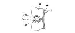
ヒートシンク2は、上記熱抵抗体6を介して冷却ブロック5上に載置されている。この熱抵抗体6は、断面ハット状に形成されている。即ち、熱抵抗体6は、ヒートシンク2を載置する円板状の天板6aと、該天板6aの周縁から略90度折曲された断面円形の周壁部6bと、該周壁部6bからさらに略90度折曲された環状のフランジ部6cとで構成されている。また、天板6aの中心には、開口6dが形成されている。
更に、この熱抵抗体6は、天板6aの周縁付近から周壁部6b及びフランジ部6cにかけて、周方向に向けて90度毎に4本の図示しないスリットが形成されている。これにより、周壁部6b及びフランジ部6cは、周方向に4分割されている状態となっている。
また、4分割されたフランジ部6cには、図2及び図3に示すように、それぞれ後述する
長ねじ(軸体)35が挿通される開口6eが形成されている。なお、この開口6eは、熱抵抗体6の半径方向に向かって長穴に形成されている。The
Further, the
Moreover, as shown in FIG.2 and FIG.3, the
また、本実施形態の熱抵抗体6は、ステンレス合金により作製されている。ここで、冷却ブロック5には、コンプレッサによって冷媒を圧縮、断熱膨張させて冷却する電気冷却方式を利用する場合があるが、その際の測定可能な温度範囲を広くする工夫が必要とされている。また、熱抵抗体6は、ヒートシンク2から冷却ブロック5へ向かう熱流の経路となっているが、この経路の断面積、距離及び素材の熱伝導率から、熱抵抗体6の熱抵抗値が決まる。この熱抵抗値が大きすぎると、ヒートシンク2の加熱効率は良いが冷却効率が悪化する。また、熱抵抗値が小さすぎると、その逆となってしまう。よって、熱抵抗体6は、バランスの良い熱抵抗値になるように設計されている。 Further, the
冷却ブロック5は、例えば、内部に空間を有した状態で外形が直方体状になるように形成されており、四隅に固定された4つの支柱30によってベース31上に載置されている。即ち、これら支柱30及びベース31は、上記支持手段7を構成している。
なお、この冷却ブロック5は、熱抵抗体6及びヒートシンク2に均等に熱流入させるため、高熱伝導性材料により作製することが望ましい。また、ヒートシンク2の昇降温速度も、示差走査熱量計にとって重要な性能の1つとなるため、冷却ブロック5自身の熱容量も小さいことが望ましい。本実施形態では、これらの理由に加え、価格及び耐熱性等を総合的に考慮して、純アルミニウムにより作製している。
上述したように、ヒートシンク2、熱抵抗体6及び冷却ブロック5は、それぞれ熱膨張率の異なる異種金属により作製されている。For example, the
The
As described above, the
冷却ブロック5の側面には、液化窒素を気化させた極低温のガスを内部の空間に供給するガス供給口32と、内部の空間で熱交換した後のガスを排出させるガス排気口33とが形成されている。更に、冷却ブロック5の側面には、これらガス供給口32及びガス排気口33に加え、図示しない電気冷却器の冷却ヘッドの挿入口34も形成されている。
つまり、この冷却ブロック5は、極低温のガスによって冷却が行われるガス冷却方式と、コンプレッサにより冷媒を圧縮、断熱膨張させて冷却が行われる電気冷却方式との2方式により、所定の温度(例えば、−90℃〜−190℃の範囲内)に冷却制御されるようになっている。On the side surface of the
That is, the
また、冷却ブロック5には、図1に示すように、上面と下面とを貫く貫通孔5aが四隅に4つ形成されていると共に、これら貫通孔5aよりも径の大きな貫通孔(第2の貫通孔)5bが中心に形成されている。4つの貫通孔5a内には、図1及び図2に示すように、一端にヘッド部35aを有する長ねじ35が移動可能に挿通されている。この長ねじ35は、ヘッド部35aが熱抵抗体6側に位置するように、熱抵抗体6の開口6e及び貫通孔5a内に挿通されており、他端が冷却ブロック5の外方に突出する長さに形成されている。また、長ねじ35の他端が、ねじ切られたねじ部35bとなっており、ナット36が螺合されるようになっている。 Further, as shown in FIG. 1, the
また、長ねじ35には、ナット36と冷却ブロック5との間に挟まれた状態で、長ねじ35の周囲を囲むようにコイルバネ37が被せられている。このコイルバネ37は、耐熱合金材料であるニッケル基耐熱合金のインコネル製のバネである。そして、コイルバネ37は、長ねじ35を他端側に向けて弾性力により常に付勢している。これにより、熱抵抗体6は、ヘッド部35aを介して長ねじ35によって引っ張られるので、冷却ブロック5に対して一定の弾性力で押し付けられている。
なお、ナット36を螺合により長ねじ35の軸方向に移動させることで、コイルバネ37の圧縮量を変化させることができ、コイルバネ37の弾性力を調整することができるようになっている。The
In addition, by moving the
また、長ねじ35には、コイルバネ37と冷却ブロック5との間に挟まれた状態で長ねじ35の周囲を囲むように、セラミックからなる環状のブッシング38が被せられている。このブッシング38は、例えば、大径部38aと該大径部38aの挟んで両側に形成された2つの縮径部38bとで一体的に構成されている。一方の縮径部38bは、冷却ブロック5の貫通孔5a内に挿入されており、長ねじ35を安定にサポートしている。また、他方の縮径部38bは、コイルバネ37の内側に挿入されており、コイルバネ37を安定にサポートしている。また、大径部38aは、コイルバネ37の外径及び貫通孔5aの内径より大きなサイズの径に形成されており、ブッシング38を位置決めさせると共に、コイルバネ37を確実に当接させている。 The
更に、長ねじ35の他端には、上述したブッシング38と同様に、コイルバネ37とナット36との間に挟まれた状態で長ねじ35の周囲を囲む環状のブッシング39が被せられている。このブッシング39は、大径部39aと1つの縮径部39bとで一体的に構成され、大径部39aがナット36側に位置するように取り付けられている。そして、縮径部39bが、コイルバネ37の内側に挿入されて、該コイルバネ37を安定にサポートしている。
上述した貫通孔5a、長ねじ35、ナット36、コイルバネ37及びブッシング38、39は、上記第1の固定手段8を構成している。Further, the other end of the
The above-described through
また、冷却ブロック5の貫通孔5b及び熱抵抗体6の開口6dには、耐熱性を有するインコネル製のワイヤ(線材)40が移動自在に挿通されており、一端側がヒートシンク2に固定されていると共に、他端側が冷却ブロック5とベース31との間で固定金具41に接続されている。このワイヤ40は、固定金具41からヒートシンク2に形成された一方の微小開口2cを通って、該ヒートシンク2内に入ると共に、他方の微小開口2cを通ってヒートシンク2外に出た後、固定金具41にて固定されている。つまり、ループ状になった先端でヒートシンク2を引っ掛けた状態で固定している。
また、固定金具41は、ベース31に対向する側の先端部41aが鉤形状になっている。また、ベース31上にも固定金具41と同様に鉤形状になった先端部42aを有する固定金具42が設けられている。この固定金具42は、基端側がねじ切られたねじ部42bとなっており、ベース31に形成されたねじ溝内に螺合により固定されている。In addition, a heat-resistant Inconel wire (wire) 40 is movably inserted into the through
In addition, the fixing
そして、両固定金具41、42は、ぞれぞれの先端部41a、42aに着脱自在に固定されたコイルバネ(第2のコイルバネ)43を介して接続されている。このコイルバネ43は、冷却ブロック5の貫通孔5b及び熱抵抗体6の開口6dを移動自在に挿通されている。また、コイルバネ43とヒートシンク2との間は、ワイヤ40によって所定距離だけ離間した状態となっている。 Both the
コイルバネ43は、ワイヤ40を介してヒートシンク2を熱抵抗体6に向けて弾性力により常に付勢している。これにより、ヒートシンク2は、コイルバネ43によって引っ張られるので、熱抵抗体6に対して一定の弾性力で押し付けられている。なお、ベース31に螺合された固定金具42の捩じ込み量を変化させることでコイルバネ43の圧縮量を変えることができ、コイルバネ43の弾性力を自在に調整することができるようになっている。 The
上記PID演算制御部13は、上述した制御熱電対12に加え、温度プログラム設定器45に接続されている。温度プログラム設定器45は、測定者によって入力された任意の温度プログラムに基づいてプログラム設定を行い、設定した温度信号をPID演算制御部13に出力している。そして、PID演算制御部13は、温度プログラム設定器45から出力された温度信号と、制御熱電対12から出力された温度信号との差から、PID(比例、微分、積分)演算を行い、適切なヒーターパワー出力をだすように電力供給部14に信号を送る。そして、電力供給部14が、この信号を受けてヒータ3に電力を供給するようになっている。これにより、ヒートシンク2は、PID演算のフィードバックループにより精密に温度制御されるようになっている。 The PID
次に、このように構成された示差走査熱量計1により、被測定試料の熱分析を行う場合について説明する。
本実施形態の示差走査熱量計1は、ヒータ3及び冷却ブロック5を備えているので、ヒートシンク2内に密閉収納された被測定試料及び基準物質を、加熱又は冷却して所望する温度条件を容易に作りだすことができる。
始めに、ヒータ3を作動させてヒートシンク2を加熱する場合について、説明する。まず測定者は、自身で決定した任意の温度プログラムを温度プログラム設定器45に入力する。温度プログラム設定器45は、この入力されたデータに基づいてプログラム設定された温度信号をPID演算制御部13に出力する。PID演算制御部13は、温度プログラム設定器45から出力された温度信号と、制御熱電対12から出力された温度信号との差から、PID演算を行い、適切なヒーターパワー出力をだすように電力供給部14に信号を送る。これを受けて、ヒータ3が作動してヒートシンク2を加熱し始める。Next, a case where the sample to be measured is subjected to thermal analysis using the
Since the
First, the case where the
ヒートシンク2は、ヒータ3によって加熱されて、例えば、700℃前後まで温度が上昇する。この熱は、ヒートシンク2、熱緩衝板20、下側保持板21及び伝熱板22を介して、試料ホルダ24及び基準物質ホルダ25に伝わる。その結果、試料ホルダ24及び基準物質ホルダ25に収納されている、被測定試料及び基準物質の温度も上昇する。そして、示差熱流検出器4は、被測定試料と基準物質との温度差を検知すると共に、検知した温度差を熱流差信号として熱電対細線27を介して出力する。この熱流差信号を得ることで、基準物質に対して被測定試料が余分に放出又は吸収する熱量を示差的に検出することができる。その結果、被測定試料の熱分析を行うことができる。特に、ヒートシンク2を、上述したようにPID制御によって高精度に温度制御しているので、熱分析を正確に行える。 The
ここで、ヒートシンク2の熱の一部は、熱抵抗体6を通って冷却ブロック5に伝わり、放熱されている。つまり、熱抵抗体6は、ヒートシンク2と冷却ブロック5との間に流れる熱の流れ道、即ち、熱流路となっている。この際、熱抵抗体6のフランジ部6cの温度、即ち、熱抵抗体6と冷却ブロック5との接合面の温度は、例えば、400℃前後となっている。 Here, part of the heat of the
次に、冷却ブロック5を、極低温のガスを利用したガス冷却方式、若しくは、冷媒を利用した電気冷却方式により、例えば−190℃に冷却を行った場合には、ヒートシンク2の熱を効率良く熱交換することができるので、ヒートシンク2に収納されている被測定試料及び基準物質を速やかに冷却することができる。この場合、ヒータ3の加熱を停止すると、ヒートシンク2を例えば−160℃前後まで冷却することができる。
このように、本実施形態の示差走査熱量計1は、加熱及び冷却を単独又は同時に行えるので、測定温度範囲を広範囲にすることができると共に、短時間で所望する温度条件にすることができる。Next, when the
Thus, since the
特に、加熱及び冷却を繰り返すと、ヒートシンク2、熱抵抗体6及び冷却ブロック5は、それぞれ膨張収縮を繰り返すことになる。この際、これらヒートシンク2、熱抵抗体6及び冷却ブロック5は、それぞれ異なる材料で形成された異種金属同士であるので、互いの接合面、即ち、ヒートシンク2と熱抵抗体6との接合面、熱抵抗体6と冷却ブロック5との接合面に、歪みや位置ずれ等が生じる。 In particular, when heating and cooling are repeated, the
ところが、本実施形態の熱抵抗体6は、第1の固定手段8によって一定の弾性力で付勢されながら冷却ブロック5に押し付けられた状態で固定されている。そのため、熱抵抗体6と冷却ブロック5との熱膨張率の違いにより、冷却ブロック5に対して熱抵抗体6が歪んだり、位置ずれ等が生じたりしても、これらに起因する応力を弾性力によって緩和することができる。つまり、歪み等に起因する応力を弾性力で吸収して、冷却ブロック5と熱抵抗体6との固定状態を常に一定の状態に維持することができる。 However, the
ここで、この第1の固定手段8についてより詳細に説明する。
まず、熱抵抗体6と冷却ブロック5とは、長ねじ35を介して接続されている。この際、冷却ブロック5の下面とナット36との間には、コイルバネ37が配されているので、コイルバネ37の弾性力がブッシング39及びナット36を介して長ねじ35に伝わっている。これにより長ねじ35は、他端側に向けて常に付勢されている。そのため熱抵抗体6は、冷却ブロック5側に引っ張られて、上述したように冷却ブロック5に対して一定の弾性力で付勢されながら押し付けられて固定されている。
そして、加熱、冷却の繰り返しにより、冷却ブロック5に対して熱抵抗体6が歪んだり、位置ずれ等が生じたりしても、それに応じてコイルバネ37が伸縮して歪み等に起因する応力を吸収する。よって、上述したように、熱抵抗体6と冷却ブロック5との固定状態を一定にすることができる。Here, the first fixing means 8 will be described in more detail.
First, the
Even if the
また、本実施形態の熱抵抗体6は、4本のスリットにより周方向に向けて4分割されているので、分割された周壁部6b及びフランジ部6cがそれぞれ歪み易くなっている。つまり、歪み等に起因する応力を分散している。そして、4分割されたフランジ部6cに、それぞれ長ねじ35が固定されているので、分散した応力を確実に吸収し易い。その結果、熱抵抗体6と冷却ブロック5との固定状態をより確実に一定状態にすることができる。また、長ねじ35が挿通されるフランジ部6cの開口6eが、半径方向に向けて長穴に形成されていることも、歪み等に起因する応力の吸収に貢献している。 Moreover, since the
更に、本実施形態のヒートシンク2は、第2の固定手段9によって一定の弾性力で付勢されながら熱抵抗体6に押し付けられた状態で固定されている。そのため、ヒートシンク2と熱抵抗体6との熱膨張率の違いにより、ヒートシンク2に対して熱抵抗体6が歪んだり、位置ずれ等が生じたりしても、これらに起因する応力を弾性力によって緩和することができる。よって、同様にヒートシンク2と熱抵抗体6との固定状態を常に一定の状態に維持することができる。 Furthermore, the
ここで、この第2の固定手段9についてより詳細に説明する。
まず、ヒートシンク2とベース31とは、ワイヤ40、コイルバネ43及び固定金具41を介して接続固定されている。この際、コイルバネ43は、ワイヤ40を介してヒートシンク2を引っ張っている。そのためヒートシンク2は、上述したように熱抵抗体6に対して一定の弾性力で付勢されながら押し付けられて固定されている。
そして、加熱、冷却の繰り返しにより、ヒートシンク2に対して熱抵抗体6が歪んだり、位置ずれ等が生じたりしても、それに応じてコイルバネ43が伸縮して歪み等に起因する応力を吸収する。よって、上述したように、熱抵抗体6と冷却ブロック5との固定状態を一定にすることができる。Here, the second fixing means 9 will be described in more detail.
First, the
Even if the
このように、本実施形態の示差走査熱量計1は、加熱、冷却を繰り返したとしても、従来のものとは異なり、熱抵抗体6とヒートシンク2との間、及び、熱抵抗体6と冷却ブロック5との間の固定状態を一定の状態に維持できるので、熱流路を安定的に維持することができる。その結果、再現性のある熱流差信号を確実に得ることができる。よって、被測定試料を高精度に測定することができ、信頼性を向上することができる。 As described above, the
特に、第1の固定手段8を構成するコイルバネ37は、インコネル製であるので、冷却ブロック5の温度がヒートシンク2からの熱により400℃程度に上昇したとしても、熱による機械的性質が変化することはない。よって、所定の弾性力で熱抵抗体6を冷却ブロック5に向けて付勢することができ、信頼性を高めることができる。
また、コイルバネ37と冷却ブロック5との間には、セラミックス製のブッシング38が介在しているので、コイルバネ37が冷却ブロック5に直接接触する必要がない。つまり、冷却ブロック5からコイルバネ37に直接熱が伝わることがなく、コイルバネ37の温度上昇を極力防止することができる。よって、過度の熱によるコイルバネ37の機械的性質の変化をより確実に防ぐことができる。また、コイルバネ37への熱影響を極力低減できるので、コイルバネ37の材料の選択性を増やすことができる。
更に、特別な機構を用いずとも、コイルバネ37、長ねじ35やナット36等により第1の固定手段8を構成できるので、構成の簡略化を図ることができると共に低コスト化を図ることができる。In particular, since the
In addition, since the
Furthermore, since the first fixing means 8 can be configured by the
また、第2の固定手段9を構成するコイルバネ43は、ワイヤ40を介してヒートシンク2に接続されて、該ヒートシンク2から所定距離だけ離間した状態となっている。そのため、ヒータ3によって直接加熱されるヒートシンク2が、例えば、725℃程度に上昇したとしても、この熱が直接コイルバネ43に伝わることがなく、コイルバネ43の温度上昇を極力防止することができる。よって、上記コイルバネ37と同様に、過度の熱によるコイルバネ43の機械的性質の変化を防ぐことができる。よって、所定の弾性力でヒートシンク2を熱抵抗体6に向けて付勢することができ、信頼性を高めることができる。
また、第1の固定手段8と同様に、特別な機構を用いずとも、コイルバネ43やワイヤ40等により第2の固定手段9を構成できるので、構成の簡略化を図ることができると共に低コスト化を図ることができる。Further, the
Further, similarly to the first fixing means 8, the second fixing means 9 can be configured by the
なお、本発明の技術範囲は上記実施の形態に限定されるものではなく、本発明の趣旨を逸脱しない範囲において種々の変更を加えることが可能である。 The technical scope of the present invention is not limited to the above embodiment, and various modifications can be made without departing from the spirit of the present invention.
例えば、上記実施形態では、第1の固定手段及び第2の固定手段を、両方を備えた構成にしたが、この場合に限られず、少なくともいずれか一方の固定手段のみを備えても構わない。こうすることで、熱抵抗体とヒートシンクとの間、又は、熱抵抗体と冷却ブロックとの間の少なくともいずれか一方の固定状態を一定の状態に維持でき、熱流路を安定的に維持することができる。
但し、上記実施形状のように、第1の固定手段及び第2の固定手段を共に備えることが好ましい。For example, in the above-described embodiment, the first fixing unit and the second fixing unit are provided with both. However, the present invention is not limited to this, and at least one of the fixing units may be provided. By doing so, the fixed state of at least one of the thermal resistor and the heat sink or between the thermal resistor and the cooling block can be maintained in a constant state, and the heat flow path can be stably maintained. Can do.
However, it is preferable to provide both the first fixing means and the second fixing means as in the above embodiment.
1 示差走査熱量計
2 ヒートシンク(収納室)
3 ヒータ
4 示差熱流検出器
5 冷却ブロック
5a 冷却ブロックの貫通孔
5b 冷却ブロックの第2の貫通孔
6 熱抵抗体
6d 熱抵抗体の開口
7 支持手段
8 第1の固定手段
9 第2の固定手段
35 長ねじ(軸体)
36 ナット
37 コイルバネ
38 ブッシング
40 ワイヤ(線材)
43 第2のコイルバネ
1
DESCRIPTION OF
36
43 Second coil spring
Claims (6)
Translated fromJapanese該収納室の周囲を囲むように取り付けられて、収納室を加熱するヒータと、
前記収納室内に設けられ、前記被測定試料と前記基準物質との温度差を検知すると共に、検知した温度差を熱流差信号として出力する示差熱流検出器と、
前記収納室の下方に一定距離離間して配置され、所定の温度に冷却制御される冷却ブロックと、
所定の熱抵抗を有するように形成され、前記冷却ブロックと前記収納室との間に介装されて両者を機械的に接続すると共に、冷却ブロックと収納室との間の熱流路を形成する熱抵抗体と、
前記冷却ブロックを支持する支持手段と、
前記冷却ブロックに対して、前記熱抵抗体を一定の弾性力で付勢しながら押し付けて固定する第1の固定手段と、前記熱抵抗体に対して、前記収納室を一定の弾性力で付勢しながら押し付けて固定する第2の固定手段とのうち、少なくともいずれか一方の固定手段とを備えていることを特徴とする示差走査熱量計。A storage chamber for storing a sample to be measured and a reference material therein;
A heater attached to surround the storage chamber and heating the storage chamber;
A differential heat flow detector that is provided in the storage chamber, detects a temperature difference between the sample to be measured and the reference material, and outputs the detected temperature difference as a heat flow difference signal;
A cooling block which is arranged at a certain distance below the storage chamber and is controlled to be cooled to a predetermined temperature;
Heat that is formed to have a predetermined thermal resistance, is interposed between the cooling block and the storage chamber, mechanically connects both, and forms a heat flow path between the cooling block and the storage chamber A resistor,
Support means for supporting the cooling block;
A first fixing means that presses and fixes the thermal resistor against the cooling block while urging with a constant elastic force, and the storage chamber is attached to the thermal resistor with a constant elastic force. A differential scanning calorimeter, comprising: at least one of the second fixing means that is pressed and fixed while being pressed.
前記第1の固定手段は、
前記冷却ブロックの上面と下面とを貫く貫通孔と、
該貫通孔内に移動自在に挿通されて、一端が前記熱抵抗体に固定されると共に他端が貫通孔内から前記冷却ブロックの外方に突出する軸体と、
該軸体の前記他端側に螺合されたナットと、
該ナットと前記冷却ブロックとの間に挟まれた状態で前記軸体の周囲を囲むように軸体に被せられ、軸体を前記他端側に向けて弾性力により付勢するコイルバネとを備え、
前記ナットを螺合により前記軸体の軸方向に移動させることで、前記コイルバネの弾性力が調整可能とされていることを特徴とする示差走査熱量計。The differential scanning calorimeter according to claim 1,
The first fixing means includes
A through-hole penetrating the upper and lower surfaces of the cooling block;
A shaft body that is movably inserted into the through hole, one end of which is fixed to the thermal resistor, and the other end projects from the through hole to the outside of the cooling block;
A nut screwed into the other end of the shaft;
A coil spring that covers the shaft body so as to surround the shaft body in a state of being sandwiched between the nut and the cooling block, and biases the shaft body toward the other end side by an elastic force. ,
The differential scanning calorimeter, wherein the elastic force of the coil spring can be adjusted by moving the nut in the axial direction of the shaft body by screwing.
前記コイルバネは、耐熱合金製材料により形成されていることを特徴とする示差走査熱量計。The differential scanning calorimeter according to claim 2,
The differential scanning calorimeter, wherein the coil spring is made of a heat-resistant alloy material.
前記軸体には、前記コイルバネと前記冷却ブロックとの間に挟まれた状態で軸体の周囲を囲むように、セラミックからなる環状のブッシングが被せられていることを特徴とする示差走査熱量計。The differential scanning calorimeter according to claim 2 or 3,
A differential scanning calorimeter, wherein the shaft body is covered with an annular bushing made of ceramic so as to surround the shaft body in a state of being sandwiched between the coil spring and the cooling block. .
前記第2の固定手段は、
前記熱抵抗体に形成された開口と、
前記冷却ブロックの上面と下面とを貫く第2の貫通孔と、
前記開口及び前記第2の貫通孔内に共に移動自在に挿通され、一端が前記収納室に固定されると共に他端が前記支持手段に固定されて、収納室を前記熱抵抗体に向けて弾性力により付勢する第2のコイルバネとを備え、
該第2のコイルバネは、自身の弾性力が調整可能に前記支持手段に固定されていることを特徴とする示差走査熱量計。In the differential scanning calorimeter according to any one of claims 1 to 4,
The second fixing means includes
An opening formed in the thermal resistor;
A second through-hole penetrating the upper and lower surfaces of the cooling block;
Both the opening and the second through hole are movably inserted, and one end is fixed to the storage chamber and the other end is fixed to the support means, and the storage chamber is elastically directed toward the thermal resistor. A second coil spring biased by force,
The differential scanning calorimeter, wherein the second coil spring is fixed to the support means so that its elastic force can be adjusted.
前記収納室と前記コイルバネとが、耐熱性を有する線材を介して固定されており、収納室とコイルバネとの間が所定距離離間していることを特徴とする示差走査熱量計。The differential scanning calorimeter according to claim 5,
The differential scanning calorimeter, wherein the storage chamber and the coil spring are fixed via a heat-resistant wire, and the storage chamber and the coil spring are separated by a predetermined distance.
Priority Applications (2)
| Application Number | Priority Date | Filing Date | Title |
|---|---|---|---|
| JP2006019122AJP4868305B2 (en) | 2006-01-27 | 2006-01-27 | Differential scanning calorimeter |
| US11/657,271US7455449B2 (en) | 2006-01-27 | 2007-01-24 | Differential scanning calorimeter |
Applications Claiming Priority (1)
| Application Number | Priority Date | Filing Date | Title |
|---|---|---|---|
| JP2006019122AJP4868305B2 (en) | 2006-01-27 | 2006-01-27 | Differential scanning calorimeter |
Publications (2)
| Publication Number | Publication Date |
|---|---|
| JP2007198959Atrue JP2007198959A (en) | 2007-08-09 |
| JP4868305B2 JP4868305B2 (en) | 2012-02-01 |
Family
ID=38368409
Family Applications (1)
| Application Number | Title | Priority Date | Filing Date |
|---|---|---|---|
| JP2006019122AExpired - Fee RelatedJP4868305B2 (en) | 2006-01-27 | 2006-01-27 | Differential scanning calorimeter |
Country Status (2)
| Country | Link |
|---|---|
| US (1) | US7455449B2 (en) |
| JP (1) | JP4868305B2 (en) |
Cited By (6)
| Publication number | Priority date | Publication date | Assignee | Title |
|---|---|---|---|---|
| CN101813652A (en)* | 2009-02-20 | 2010-08-25 | 精工电子纳米科技有限公司 | Differential scanning calorimetry |
| JP2011523060A (en)* | 2008-06-06 | 2011-08-04 | パーキンエルマー・ヘルス・サイエンシズ・インコーポレーテッド | Calorimeter, method using the same, and control system therefor |
| JP2013178275A (en)* | 2013-05-24 | 2013-09-09 | Hitachi High-Tech Science Corp | Differential scanning calorimeter |
| CN108931552A (en)* | 2017-05-26 | 2018-12-04 | 株式会社理学 | Apparatus for thermal analysis |
| CN113390918A (en)* | 2020-03-12 | 2021-09-14 | 日本株式会社日立高新技术科学 | Thermal analysis device |
| JP2022074017A (en)* | 2020-10-30 | 2022-05-17 | アントン パール ゲーエムベーハー | Measuring device having electrothermal transducer for adjusting thermal resistance, and method of operating the same |
Families Citing this family (16)
| Publication number | Priority date | Publication date | Assignee | Title |
|---|---|---|---|---|
| GB0415968D0 (en)* | 2004-07-16 | 2004-08-18 | Heath Scient Co Ltd | Calorimeter |
| JP4831487B2 (en)* | 2006-12-21 | 2011-12-07 | エスアイアイ・ナノテクノロジー株式会社 | Differential scanning calorimeter |
| US20090081721A1 (en)* | 2007-04-11 | 2009-03-26 | The Regents Of The University Of California | High-throughput cell assays |
| US8147133B2 (en)* | 2009-05-26 | 2012-04-03 | The United States Of America As Represented By The Secretary Of The Navy | Top loaded twin cell calorimeter system with removable reference |
| US20110164652A1 (en)* | 2010-01-05 | 2011-07-07 | Refalo Lee A | Differential Thermoelectric Cooler Calorimeter |
| JP5642525B2 (en)* | 2010-02-02 | 2014-12-17 | 株式会社日立ハイテクサイエンス | Differential scanning calorimeter |
| US8764289B2 (en)* | 2011-12-21 | 2014-07-01 | Unison Industries, Llc | Expandable/retractable thermocouple |
| RU2529455C1 (en) | 2013-07-30 | 2014-09-27 | Шлюмберже Текнолоджи Б.В. | Method to determine thermal volume expansion coefficient of liquid |
| US10617891B2 (en) | 2015-04-23 | 2020-04-14 | Sun Nuclear Corporation | Radiation detector calibration |
| WO2018160763A1 (en) | 2017-02-28 | 2018-09-07 | Sun Nuclear Corporation | Radiation therapy treatment verification with electronic portal imaging device transit images |
| US11278744B2 (en) | 2018-09-28 | 2022-03-22 | Sun Nuclear Corporation | Systems and methods to account for tilt of a radiation measurement system |
| US11474054B2 (en)* | 2018-10-22 | 2022-10-18 | Equistar Chemicals, Lp | Temperature control apparatuses and methods |
| US12011616B2 (en) | 2019-07-10 | 2024-06-18 | Sun Nuclear Corporation | Image-based radiation therapy quality assurance |
| US11378700B2 (en) | 2019-07-10 | 2022-07-05 | Sun Nuclear Corporation | Scintillator-based radiation therapy quality assurance |
| US11600004B2 (en) | 2019-07-10 | 2023-03-07 | Sun Nuclear Corporation | Image-based radiation therapy quality assurance |
| US12201850B2 (en) | 2022-06-16 | 2025-01-21 | Sun Nuclear Corporation | High dose rate radiation therapy systems and dosimetry |
Citations (5)
| Publication number | Priority date | Publication date | Assignee | Title |
|---|---|---|---|---|
| JPH05223764A (en)* | 1992-02-07 | 1993-08-31 | Rigaku Corp | Furnace unit of differential scanning calorimeter |
| JPH0635171Y2 (en)* | 1988-06-15 | 1994-09-14 | セイコー電子工業株式会社 | Thermal analyzer |
| JP2002310965A (en)* | 2001-01-26 | 2002-10-23 | Ta Instruments Waters Llc | Thermal analysis assembly having dispersively arrayed heat resistor and integrated flange for mounting various coolers |
| WO2005003992A1 (en)* | 2003-07-04 | 2005-01-13 | Mettler-Toledo Gmbh | Method and device for a thermoanalytical material analysis |
| JP2005147928A (en)* | 2003-11-18 | 2005-06-09 | Sii Nanotechnology Inc | Differential scanning calorimeter with second heater |
Family Cites Families (11)
| Publication number | Priority date | Publication date | Assignee | Title |
|---|---|---|---|---|
| US3267728A (en)* | 1964-08-25 | 1966-08-23 | Honeywell Inc | Dynamic automatically controlled calorimeter and melting point device |
| US3384819A (en)* | 1965-03-19 | 1968-05-21 | Gen Microwave Corp | Microwave power calorimeter using a thin-film thermopile load |
| US3451267A (en)* | 1966-02-07 | 1969-06-24 | Richard G Wiegert | Calorimeter |
| CH639199A5 (en)* | 1979-05-09 | 1983-10-31 | Marcel Birukoff | DEVICE FOR MEASURING THE HEATING CONDUCT OF A COMPONENT. |
| JPH07122619B2 (en) | 1988-10-13 | 1995-12-25 | セイコー電子工業株式会社 | Analysis equipment |
| JPH0765974B2 (en) | 1988-10-26 | 1995-07-19 | セイコー電子工業株式会社 | Cooling device for heating furnace of thermal analyzer |
| US5551282A (en)* | 1995-03-20 | 1996-09-03 | Badger Meter, Inc. | Method and apparatus for measuring volume correction using molar quantities |
| US6146013A (en)* | 1995-05-19 | 2000-11-14 | Mettler-Toledo Gmbh | Differential thermal analysis system including dynamic mechanical analysis |
| JP4011531B2 (en) | 2003-09-04 | 2007-11-21 | エスアイアイ・ナノテクノロジー株式会社 | Thermal analyzer with cooling mechanism |
| JP4812017B2 (en)* | 2006-07-26 | 2011-11-09 | エスアイアイ・ナノテクノロジー株式会社 | Thermal analysis apparatus and drying method thereof |
| JP4831487B2 (en)* | 2006-12-21 | 2011-12-07 | エスアイアイ・ナノテクノロジー株式会社 | Differential scanning calorimeter |
- 2006
- 2006-01-27JPJP2006019122Apatent/JP4868305B2/ennot_activeExpired - Fee Related
- 2007
- 2007-01-24USUS11/657,271patent/US7455449B2/ennot_activeExpired - Fee Related
Patent Citations (5)
| Publication number | Priority date | Publication date | Assignee | Title |
|---|---|---|---|---|
| JPH0635171Y2 (en)* | 1988-06-15 | 1994-09-14 | セイコー電子工業株式会社 | Thermal analyzer |
| JPH05223764A (en)* | 1992-02-07 | 1993-08-31 | Rigaku Corp | Furnace unit of differential scanning calorimeter |
| JP2002310965A (en)* | 2001-01-26 | 2002-10-23 | Ta Instruments Waters Llc | Thermal analysis assembly having dispersively arrayed heat resistor and integrated flange for mounting various coolers |
| WO2005003992A1 (en)* | 2003-07-04 | 2005-01-13 | Mettler-Toledo Gmbh | Method and device for a thermoanalytical material analysis |
| JP2005147928A (en)* | 2003-11-18 | 2005-06-09 | Sii Nanotechnology Inc | Differential scanning calorimeter with second heater |
Cited By (13)
| Publication number | Priority date | Publication date | Assignee | Title |
|---|---|---|---|---|
| JP2011523060A (en)* | 2008-06-06 | 2011-08-04 | パーキンエルマー・ヘルス・サイエンシズ・インコーポレーテッド | Calorimeter, method using the same, and control system therefor |
| CN101813652A (en)* | 2009-02-20 | 2010-08-25 | 精工电子纳米科技有限公司 | Differential scanning calorimetry |
| JP2010190807A (en)* | 2009-02-20 | 2010-09-02 | Sii Nanotechnology Inc | Differential scanning calorimeter |
| JP2013178275A (en)* | 2013-05-24 | 2013-09-09 | Hitachi High-Tech Science Corp | Differential scanning calorimeter |
| JP2018200207A (en)* | 2017-05-26 | 2018-12-20 | 株式会社リガク | Thermal analyzer |
| KR20180129626A (en) | 2017-05-26 | 2018-12-05 | 가부시키가이샤 리가쿠 | Thermal analysis equipment |
| CN108931552A (en)* | 2017-05-26 | 2018-12-04 | 株式会社理学 | Apparatus for thermal analysis |
| KR102328943B1 (en)* | 2017-05-26 | 2021-11-22 | 가부시키가이샤 리가쿠 | Thermal analysis equipment |
| CN108931552B (en)* | 2017-05-26 | 2022-03-11 | 株式会社理学 | Thermal analysis device |
| CN113390918A (en)* | 2020-03-12 | 2021-09-14 | 日本株式会社日立高新技术科学 | Thermal analysis device |
| JP2021144016A (en)* | 2020-03-12 | 2021-09-24 | 株式会社日立ハイテクサイエンス | Thermal analyzer |
| JP7407051B2 (en) | 2020-03-12 | 2023-12-28 | 株式会社日立ハイテクサイエンス | Thermal analyzer |
| JP2022074017A (en)* | 2020-10-30 | 2022-05-17 | アントン パール ゲーエムベーハー | Measuring device having electrothermal transducer for adjusting thermal resistance, and method of operating the same |
Also Published As
| Publication number | Publication date |
|---|---|
| US20070189357A1 (en) | 2007-08-16 |
| US7455449B2 (en) | 2008-11-25 |
| JP4868305B2 (en) | 2012-02-01 |
Similar Documents
| Publication | Publication Date | Title |
|---|---|---|
| JP4868305B2 (en) | Differential scanning calorimeter | |
| JP4831487B2 (en) | Differential scanning calorimeter | |
| JP5642525B2 (en) | Differential scanning calorimeter | |
| EP2572252B1 (en) | Heating in material testing apparatus | |
| JP5212407B2 (en) | Thermal fatigue test equipment | |
| KR102328943B1 (en) | Thermal analysis equipment | |
| JP4181776B2 (en) | Thermal analysis assembly with distributed thermal resistors and integrated flange for mounting various cooling devices | |
| JP2003031884A (en) | Apparatus and method for controlling temperature of semiconductor module | |
| JP5187663B2 (en) | Insulated calorimeter | |
| JP4116526B2 (en) | Differential scanning calorimeter with second heater | |
| JP4011531B2 (en) | Thermal analyzer with cooling mechanism | |
| JP5283535B2 (en) | Differential scanning calorimeter | |
| US20240261790A1 (en) | Device for controlling the temperature of a measuring cell and method for operating the device | |
| WO2008153913A1 (en) | System and method for thermal analysis using variable thermal resistance | |
| JP5942889B2 (en) | Heat transfer mechanism and thermal analysis apparatus having the same | |
| JP2013050640A (en) | Temperature controller | |
| US20060266895A1 (en) | Temperature controlled, universal mounting assembly | |
| JP5551811B2 (en) | Differential scanning calorimeter | |
| JP3147015U (en) | Differential scanning calorimeter | |
| JP2009150661A (en) | Thermal analyzer | |
| JP2001165880A (en) | Sample container for thermal analysis and manufacturing method of the container | |
| JP2002181679A (en) | High temperature hardness tester | |
| JPH06102216A (en) | Thermal analyzer | |
| JP2022126562A (en) | Constant temperature device and piezoelectric constant d33 measurement method | |
| CN113933143A (en) | Diamond pressure cavity pressurizing device |
Legal Events
| Date | Code | Title | Description |
|---|---|---|---|
| A621 | Written request for application examination | Free format text:JAPANESE INTERMEDIATE CODE: A621 Effective date:20080828 | |
| A131 | Notification of reasons for refusal | Free format text:JAPANESE INTERMEDIATE CODE: A131 Effective date:20110830 | |
| A521 | Request for written amendment filed | Free format text:JAPANESE INTERMEDIATE CODE: A523 Effective date:20111006 | |
| TRDD | Decision of grant or rejection written | ||
| A01 | Written decision to grant a patent or to grant a registration (utility model) | Free format text:JAPANESE INTERMEDIATE CODE: A01 Effective date:20111025 | |
| A01 | Written decision to grant a patent or to grant a registration (utility model) | Free format text:JAPANESE INTERMEDIATE CODE: A01 | |
| RD03 | Notification of appointment of power of attorney | Free format text:JAPANESE INTERMEDIATE CODE: A7423 Effective date:20111104 | |
| A61 | First payment of annual fees (during grant procedure) | Free format text:JAPANESE INTERMEDIATE CODE: A61 Effective date:20111104 | |
| R150 | Certificate of patent or registration of utility model | Ref document number:4868305 Country of ref document:JP Free format text:JAPANESE INTERMEDIATE CODE: R150 Free format text:JAPANESE INTERMEDIATE CODE: R150 | |
| FPAY | Renewal fee payment (event date is renewal date of database) | Free format text:PAYMENT UNTIL: 20141125 Year of fee payment:3 | |
| S531 | Written request for registration of change of domicile | Free format text:JAPANESE INTERMEDIATE CODE: R313531 | |
| S533 | Written request for registration of change of name | Free format text:JAPANESE INTERMEDIATE CODE: R313533 | |
| R350 | Written notification of registration of transfer | Free format text:JAPANESE INTERMEDIATE CODE: R350 | |
| FPAY | Renewal fee payment (event date is renewal date of database) | Free format text:PAYMENT UNTIL: 20141125 Year of fee payment:3 | |
| R371 | Transfer withdrawn | Free format text:JAPANESE INTERMEDIATE CODE: R371 | |
| R250 | Receipt of annual fees | Free format text:JAPANESE INTERMEDIATE CODE: R250 | |
| R250 | Receipt of annual fees | Free format text:JAPANESE INTERMEDIATE CODE: R250 | |
| R250 | Receipt of annual fees | Free format text:JAPANESE INTERMEDIATE CODE: R250 | |
| R250 | Receipt of annual fees | Free format text:JAPANESE INTERMEDIATE CODE: R250 | |
| R250 | Receipt of annual fees | Free format text:JAPANESE INTERMEDIATE CODE: R250 | |
| LAPS | Cancellation because of no payment of annual fees | ||
| R250 | Receipt of annual fees | Free format text:JAPANESE INTERMEDIATE CODE: R250 | |
| R250 | Receipt of annual fees | Free format text:JAPANESE INTERMEDIATE CODE: R250 | |
| LAPS | Cancellation because of no payment of annual fees |