JP2007197206A - Printing apparatus and printing method - Google Patents
Printing apparatus and printing methodDownload PDFInfo
- Publication number
- JP2007197206A JP2007197206AJP2006020971AJP2006020971AJP2007197206AJP 2007197206 AJP2007197206 AJP 2007197206AJP 2006020971 AJP2006020971 AJP 2006020971AJP 2006020971 AJP2006020971 AJP 2006020971AJP 2007197206 AJP2007197206 AJP 2007197206A
- Authority
- JP
- Japan
- Prior art keywords
- sheet
- printing
- print job
- sheets
- sheet bundle
- Prior art date
- Legal status (The legal status is an assumption and is not a legal conclusion. Google has not performed a legal analysis and makes no representation as to the accuracy of the status listed.)
- Pending
Links
Images


Classifications
- G—PHYSICS
- G06—COMPUTING OR CALCULATING; COUNTING
- G06K—GRAPHICAL DATA READING; PRESENTATION OF DATA; RECORD CARRIERS; HANDLING RECORD CARRIERS
- G06K15/00—Arrangements for producing a permanent visual presentation of the output data, e.g. computer output printers
- G06K15/02—Arrangements for producing a permanent visual presentation of the output data, e.g. computer output printers using printers
- B—PERFORMING OPERATIONS; TRANSPORTING
- B41—PRINTING; LINING MACHINES; TYPEWRITERS; STAMPS
- B41J—TYPEWRITERS; SELECTIVE PRINTING MECHANISMS, i.e. MECHANISMS PRINTING OTHERWISE THAN FROM A FORME; CORRECTION OF TYPOGRAPHICAL ERRORS
- B41J3/00—Typewriters or selective printing or marking mechanisms characterised by the purpose for which they are constructed
- B41J3/60—Typewriters or selective printing or marking mechanisms characterised by the purpose for which they are constructed for printing on both faces of the printing material
Landscapes
- Engineering & Computer Science (AREA)
- General Engineering & Computer Science (AREA)
- Physics & Mathematics (AREA)
- General Physics & Mathematics (AREA)
- Theoretical Computer Science (AREA)
- Accessory Devices And Overall Control Thereof (AREA)
- Paper Feeding For Electrophotography (AREA)
- Controlling Sheets Or Webs (AREA)
- Registering Or Overturning Sheets (AREA)
- Folding Of Thin Sheet-Like Materials, Special Discharging Devices, And Others (AREA)
Abstract
Translated fromJapaneseDescription
Translated fromJapanese本発明は、印刷装置及び印刷方法に関する。 The present invention relates to a printing apparatus and a printing method.
従来から、シートに印刷処理をして排紙トレイ等の積載部にシートを排出する印刷装置が知られている。そして、印刷処理されたシートの積載部への排出方法(排出モード)としては、次の2方法が知られている。第1の方法は、印刷処理された面を上向きにしてシートを排出するフェイスアップ(FU)排出方法である。第2の方法は、印刷処理された面を下向きにしてシートを排出するフェイスダウン(FD)排出方法である。印刷装置は、シートに印刷処理する印刷処理部は通常1箇所しか持たないので、フェイスアップ排出方法とフェイスダウン排出方法を、シートを反転させることにより切り替えている。 2. Description of the Related Art Conventionally, printing apparatuses that print a sheet and discharge the sheet to a stacking unit such as a discharge tray are known. The following two methods are known as a discharge method (discharge mode) of the printed sheet to the stacking unit. The first method is a face-up (FU) discharge method that discharges a sheet with the printed surface facing upward. The second method is a face-down (FD) discharge method in which the sheet is discharged with the printed surface facing downward. Since the printing apparatus usually has only one print processing unit for performing printing processing on a sheet, the face-up discharge method and the face-down discharge method are switched by inverting the sheet.
以上のようなフェイスアップ排出方法とフェイスダウン排出方法を、操作者の指示により切り替える印刷装置が知られている(例えば、特許文献1参照。)。 There is known a printing apparatus that switches between the face-up discharge method and the face-down discharge method as described above according to an instruction from an operator (for example, see Patent Document 1).
上記の従来技術では、印刷装置の操作者が、フェイスアップ排出方法とフェイスダウン排出方法のうち所望の排出方法を選択することが可能である。しかし、上記の従来技術では以下のような問題が生じることが考えられる。 In the above-described conventional technology, the operator of the printing apparatus can select a desired discharge method among the face-up discharge method and the face-down discharge method. However, the following problems may occur in the above-described conventional technology.
印刷装置が備える積載部に複数の印刷ジョブにかかる複数のシート束を積載する場合、上記の従来技術では、以下のような指示が可能である。それは、1番目に実行する印刷ジョブにかかるシート束の排出方法をフェイスダウン排出方法とし、2番目に実行する印刷ジョブにかかるシート束の排出方法をフェイスアップ排出方法とする指示である。この場合、印刷装置が備える積載部には、フェイスダウン排出方法で排出されたシート束と、フェイスアップ排出方法で排出されたシート束とが混在することとなる。例えば、印刷装置にて印刷処理された複数の印刷ジョブにかかる複数のシート束を、印刷装置とは異なるシート処理装置で一括して処理する場合に問題が生じる。その問題とは、フェイスダウン排出方法で排出されたシート束と、フェイスアップ排出方法で排出されたシート束とが混在することにより一括したシート処理を実行すると不具合が生じるという問題である。例えば、シート処理装置にてシートの一端を断裁する断裁処理を実行する場合、フェイスダウン排出方法で排出したシート束と、フェイスアップ排出方法で排出したシート束とを適切に並び換えないと不具合が生じる。その不具合とは、あるシート束では印刷処理された面の右端部が断裁され、あるシート束では印刷処理された面の左端部が断裁されてしまうという不具合である。 In the case of stacking a plurality of sheet bundles related to a plurality of print jobs on the stacking unit provided in the printing apparatus, the above-described conventional technique can give the following instructions. It is an instruction that the sheet bundle discharge method for the first executed print job is the face-down discharge method, and the sheet bundle discharge method for the second executed print job is the face-up discharge method. In this case, a sheet bundle discharged by the face-down discharge method and a sheet bundle discharged by the face-up discharge method are mixed in the stacking unit included in the printing apparatus. For example, a problem occurs when a plurality of sheet bundles related to a plurality of print jobs subjected to print processing by the printing apparatus are collectively processed by a sheet processing apparatus different from the printing apparatus. The problem is that a problem occurs when batch sheet processing is performed due to a mixture of sheet bundles discharged by the face-down discharge method and sheet bundles discharged by the face-up discharge method. For example, when a sheet processing apparatus performs a cutting process for cutting one end of a sheet, the sheet bundle discharged by the face-down discharge method and the sheet bundle discharged by the face-up discharge method are not properly rearranged. Arise. The defect is a defect that the right end portion of the printed surface is cut in a certain sheet bundle and the left end portion of the printed surface is cut in a certain sheet bundle.
本願発明は、上記の問題点を鑑みてなされたものであり、積載手段にシートを反転させて排出する第1の排出モードとシートを反転させることなく排出する第2の排出モードのいずれかにてシートを排出可能な印刷装置において、積載手段に連続して排出される複数の印刷ジョブにかかるシート束の排出状態を同一にすることを目的とする。 The present invention has been made in view of the above-described problems, and is either a first discharge mode in which sheets are reversed and discharged by a stacking unit or a second discharge mode in which sheets are discharged without being reversed. In a printing apparatus capable of discharging sheets, it is an object to make the discharge state of sheet bundles related to a plurality of print jobs discharged continuously to the stacking means the same.
上記目的を達成するために、本発明の印刷装置は、複数ページの画像データを含む印刷ジョブを入力する入力手段と、前記入力手段により入力された印刷ジョブに基づいて、複数のシートに印刷処理する印刷手段と、前記印刷手段により印刷処理された複数のシートをシート束として積載する積載手段と、前記シート束にかかるシートを、前記積載手段に積載される前に反転させる反転手段と、前記シート束にかかるシートを前記反転手段により反転処理させて前記積載手段に排出する第1の排出モードと、前記シート束にかかるシートを前記反転手段により反転処理させることなく前記積載手段に排出する第2の排出モードのいずれかのモードを選択する選択手段とを有し、前記選択手段は、前記第1の印刷ジョブに引き続き第2の印刷ジョブに基づいて印刷処理を実行する場合、前記第1の印刷ジョブにかかるシート束の排出のために選択した排出モードを、前記第2の印刷ジョブにかかるシート束の排出のために選択することを特徴とする。 In order to achieve the above object, a printing apparatus according to the present invention includes an input unit that inputs a print job including image data of a plurality of pages, and print processing on a plurality of sheets based on the print job input by the input unit. Printing means, stacking means for stacking a plurality of sheets printed by the printing means as a sheet bundle, reversing means for reversing the sheets on the sheet bundle before being stacked on the stacking means, A first discharge mode in which the sheet on the sheet bundle is reversed by the reversing unit and discharged to the stacking unit; and the sheet on the sheet bundle is discharged to the stacking unit without being reversed by the reversing unit. Selecting means for selecting any one of the two discharge modes, wherein the selecting means continues to the second print job after the first print job. When the print processing is executed based on the print job, the discharge mode selected for discharging the sheet bundle related to the first print job is selected for discharging the sheet bundle related to the second print job. It is characterized by.
また、本発明の印刷方法は、複数ページの画像データを含む印刷ジョブを入力する入力工程と、前記入力工程により入力された印刷ジョブに基づいて、複数のシートに印刷処理する印刷手段と、前記シート束にかかるシートを、反転させる反転工程と、前記シート束にかかるシートを前記反転工程により反転処理させて前記積載部に排出する第1の排出モードと、前記シート束にかかるシートを前記反転工程により反転処理させることなく前記積載部に排出する第2の排出モードのいずれかのモードを選択する選択工程と、前記印刷工程により印刷処理された複数のシートを前記選択工程にて選択した排出モードにて排出させて積載部に積載する積載工程とを有し、前記選択工程は、前記第1の印刷ジョブに引き続き第2の印刷ジョブに基づいて印刷処理を実行する場合、前記第1の印刷ジョブにかかるシート束の排出のために選択した排出モードを、前記第2の印刷ジョブにかかるシート束の排出のために選択することを特徴とする。 Further, the printing method of the present invention includes an input step for inputting a print job including image data of a plurality of pages, a printing unit for performing print processing on a plurality of sheets based on the print job input in the input step, A reversing step of reversing the sheets on the sheet bundle, a first discharge mode for reversing the sheets on the sheet bundle by the reversing step and discharging the sheets to the stacking unit, and the reversing of the sheets on the sheet bundle A selection step of selecting any one of the second discharge modes to be discharged to the stacking unit without performing a reversal process in the step, and a discharge in which a plurality of sheets printed in the printing step are selected in the selection step A stacking process for discharging in the mode and stacking on the stacking unit, and the selection process is based on a second print job following the first print job. When executing the printing process, the discharge mode selected for discharging the sheet bundle related to the first print job is selected for discharging the sheet bundle related to the second print job. To do.
本発明によれば、積載手段(積載部)にシートを反転させて排出する第1の排出モードとシートを反転させることなく排出する第2の排出モードのいずれかにてシートを排出可能な印刷装置及び印刷方法において、積載手段(積載部)に連続して排出される複数の印刷ジョブにかかるシート束の排出状態を同一にすることができる。 According to the present invention, printing capable of discharging a sheet in either the first discharge mode in which the sheet is reversed and discharged to the stacking unit (stacking unit) or the second discharge mode in which the sheet is discharged without being reversed. In the apparatus and the printing method, it is possible to make the discharge state of the sheet bundle related to a plurality of print jobs discharged continuously to the stacking unit (stacking unit) the same.
以下、添付図面を参照して本発明の実施の形態を説明する。 Embodiments of the present invention will be described below with reference to the accompanying drawings.
(第1の実施形態)
<印刷システム(印刷装置)の全体構成>
図1は、本発明の実施形態に対応する印刷システム(広義の印刷装置)の全体構成を示す図である。(First embodiment)
<Overall configuration of printing system (printing apparatus)>
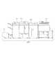
FIG. 1 is a diagram illustrating an overall configuration of a printing system (a printing device in a broad sense) corresponding to an embodiment of the present invention.
図1において、105は印刷装置であり、画像データに基づいてシートに印刷処理をするとともに、印刷処理されたシートをスタッカ装置104へ搬送する。スタッカ装置104は、印刷装置105から搬送されたシートをスタックトレイ(不図示)に積載する。また、スタッカ装置104は、印刷装置105から搬送されたシートをスタックトレイに積載することなく、くるみ製本装置103へ搬送することもできる。くるみ製本装置103は、印刷装置105からスタッカ装置104を介して搬送される複数のシートSを後述する集積トレイ42にシート束S1として積載する。そして、集積トレイ42に積載されたシート束S1を後述するカバーシート積載トレイ70に積載されたカバーシートS2でくるむことでくるみ製本物を作成する。 In FIG. 1,
なお、くるみ製本装置103は、スタッカ装置104から搬送されたシートSを集積トレイ42に積載することなく、中綴じ製本装置102へ搬送することもできる。中綴じ製本装置102は、印刷装置105からくるみ製本装置103を介して搬送される複数のシートSからなるシート束S1に対してステイプル処理を実行することで中綴じ製本物を作成する。なお、中綴じ製本装置102にて作成された中綴じ製本物は、断裁装置101に搬送され断裁処理が実行される。なお、断裁処理とは、複数枚のシートで構成されるシート束の少なくとも一端を切断するシート処理をいう。 Note that the
なお、図1では印刷システム(印刷装置)2000を、印刷装置105、スタッカ装置104、くるみ製本装置103、中綴じ製本装置102及び断裁装置101で構成したが他の構成であってもよい。少なくとも印刷装置105とスタッカ装置104を組み合わせることで、本実施形態に対応する印刷システム(印刷装置)2000を構成することができる。 In FIG. 1, the printing system (printing apparatus) 2000 includes the
<印刷装置の制御構成>
図2は、本発明の実施形態に対応する印刷装置105の制御構成を示すブロック図である。<Control configuration of printing device>
FIG. 2 is a block diagram showing a control configuration of the
図2において201はスキャナ部であり、複数枚の原稿(紙等のシートに画像が印刷されたもの)を光学的に読み取って画像データを生成するとともに、読み取られた画像データに対して画像処理(例えば、シェーディング補正処理)を実行する。そして、スキャナ部201は、画像処理が実行された複数ページの画像データを1つの印刷ジョブとしてハードディスク(HDD)209へ記憶させる。202は外部I/Fであり、印刷装置105にネットワーク232を介して接続されたコンピュータ端末233から複数ページの画像データを含む印刷ジョブを受信する。そして、外部I/F202は、コンピュータ端末233から受信した印刷ジョブをハードディスク209へ記憶させる。203はプリンタ部であり、ハードディスク209に記憶された印刷ジョブに基づいて、複数のシートSに印刷処理を実行する。なお、印刷ジョブは複数ページの画像データから構成されているので、複数の画像データが複数のシートSの各々に印刷処理される。204は操作部であり、印刷装置105の操作者による各種の指示を受け付け、受け付けた指示をメモリコントローラ部206へ伝えることで印刷装置105に各種の設定を行うものである。また、外部I/F202は、ネットワーク232を介してオフラインくるみ製本装置234及びオフライン断裁装置235に接続されている。前述したくるみ製本装置103は、印刷装置105から搬送された印刷済みのシートSを直接的に受け入れる方式(以下、オンライン方式)であった。それに対して、オフラインくるみ製本装置234は、印刷システム2000のスタッカ装置104に印刷処理されたシートを排紙した後に、印刷システム2000の操作者により運搬されたシート束を処理するものである。このように、印刷装置105が印刷処理したシートを直接的に受け入れるのではなく、操作者により運搬されたシート束を受け入れる方式をオフライン方式という。また、前述した断裁装置101は、印刷装置105から搬送された印刷済みのシートSを直接的に受け入れる方式(以下、オンライン方式)であった。それに対して、オフライン断裁装置235は、印刷システム2000のスタッカ装置104に印刷処理されたシートを排紙した後に、印刷システム2000の操作者により運搬されたシート束を断裁処理するものである。なお、オフラインくるみ製本装置234は、通常はオフライン断裁装置235にて断裁処理されたシート束に対してくるみ製本処理を施す。従って、第1の実施形態のシステムでは、スタッカ装置104に排紙されたシート束を操作者がオフライン断裁装置235へ運搬して断裁処理を施す。その後、オフライン断裁装置235にて断裁処理が施されたシート束を操作者がオフラインくるみ製本装置234へ運搬してくるみ製本処理を施す。なお、オフラインくるみ製本装置234は、印刷装置と直接的に接続されていない点を除いては、くるみ製本装置103と同様の構造であるものとする。また、オフライン断裁装置235は、印刷装置と直接的に接続されていない点を除いては、断裁装置101と同様の構造であるものとする。 In FIG. 2, a
CPU205は、ROM207から読み込んだプログラムをRAM208へ書き込み、RAM208を用いてプログラムを実行することで印刷装置105を含む印刷システム2000の全体を制御する。なお、ROM207には、外部I/F202が外部装置から印刷ジョブとして受信したPDL(Page Description language:ページ記述言語)コードデータを解釈するためのプログラムが記憶されている。さらに、ROM207には、PDLコードデータを解釈した後にプリント部203にて印刷可能なデータを生成するためのプログラムが記憶されている。メモリコントローラ部206は、ROM207、RAM208、及びハードディスク209に対する、各部からのアクセスを制御する。 The CPU 205 controls the
圧縮伸長部210は、JBIGやJPEG等といった各種圧縮方式によってRAM208、ハードディスク209に記憶されている画像データに圧縮処理を実行することができる。また、圧縮伸長部210は、各種圧縮方式により圧縮処理された画像データを伸長する伸長処理を実行することができる。 The compression /
回転部231は、ハードディスク209に記憶された画像データをプリンタ部203へ送信して印刷処理を実行させるにあたって、画像データを回転させる必要がある場合に、回転処理を実行するものである。回転部231は、回転処理として、画像データの天地方向を逆転させる180°回転処理や、90°回転処理等の、任意の角度の回転処理を実行することができる。なお、回転部231が実行する回転処理の回転角度の設定等は、CPU205からできるものとする。 The rotation unit 231 executes the rotation process when the image data needs to be rotated when the image data stored in the
オプションI/F230は、CPU205が、印刷装置105に接続されるオプション装置としてのスタッカ装置104、くるみ製本装置103、中綴じ製本装置102及び断裁装置101と通信するためのインターフェースである。スタッカ装置104、くるみ製本装置103、中綴じ製本装置102及び断裁装置101は各々内部の動作を制御するためのCPU(不図示)を有する。そして、印刷装置105のCPU205は、オプションI/F230を介して各オプション装置のCPUを制御するための制御コマンドを送信することにより、スタッカ装置104、くるみ製本装置103、中綴じ製本装置102及び断裁装置101を制御する。 The option I /
<印刷装置の構成>
次に、印刷装置105の構成について、図3を用いて説明する。<Configuration of printing device>
Next, the configuration of the
印刷装置105は、大きく分けてスキャナ部201およびプリンタ部203から構成される。スキャナ部201は、原稿給送ユニット250に積載されたシート束をその積載順に従って先頭(最上部)から順次1枚ずつプラテンガラス211上に給送する。そして原稿給送ユニット250は、スキャナユニット220による読み取り動作が終了した後、排出トレイ219に排出する。スキャナユニット210は、プラテンガラス211上に原稿シートが搬送されると、ランプ212を点灯して光学ユニット213の移動を開始させ、シート状の原稿を下方から照射しながら走査する。原稿からの反射光が複数のミラー214、215、216およびレンズ217を通ってCCDイメージセンサ(以下、CCD)218に導かれ、走査された原稿上の画像はCCD218によって画像データとして読み取られる。CCD218で読み取られた画像データは、所定の画像処理が施された後、ハードディスク209に記憶される。 The
プリンタ部203は、ハードディスク209から読み出される画像データに対応するレーザ光を、レーザドライバ321によって駆動されるレーザ発光部322から出力する。レーザ光を照射された感光ドラム323にはレーザ光に応じた静電潜像が形成され、現像器324は静電潜像の部分に現像剤(例えば、トナー)を付着させる。 The
一方、レーザ光の照射開始と同期したタイミングで、カセット311、カセット312、カセット313、カセット314、手差しトレイ315の何れかからシートSを給紙し、搬送路331を経由して転写部325まで搬送する。ここで、手差しトレイ315には、シートSが載置されたことを検知するシート検知センサ315aが設けられている。転写部325は感光ドラム323に付着している現像剤をシートS上に転写する。現像剤が転写されたシートSは搬送ベルト326によって定着部327に搬送され、定着部327にて加熱される。それによりシートS上の現像剤は、シートSに定着される。現像剤が定着したシートSは、搬送路335、334を経由してスタッカ装置104に搬送される。スタッカ装置104にシートSを搬送する(排出する)にあたっては、フェイスアップ排出モードとフェイスダウン排出モードとがある。フェイスアップ排出モードは、印刷処理がされた面を上向きにして排出するモードであり、搬送路335から搬送されたシートSを反転させることなく搬送路334から排出する。一方、フェイスダウン排出モードは、印刷処理がされた面を下向きにして排出するモードであり、搬送路335から搬送されたシートSを反転させてから搬送路334へ搬送する。具体的には、CPU205は定着部327を経由したシートSを搬送路335へ搬送せずに搬送路336、338まで導くようプリンタ部203を制御する。そしてその後に、シートSを逆方向に搬送し、搬送路337、334を経由してスタッカ装置104にシートを排出する。印刷装置105は、CPU205の指示により、フェイスダウン排出モード又はフェイスアップ排出モードのいずれかを用いてシートSをスタッカ装置104へ排出することができる。 On the other hand, the sheet S is fed from any one of the
<スタッカ装置の構成>
次に、スタッカ装置104の構成について、図13を用いて説明する。<Configuration of stacker device>
Next, the configuration of the
スタッカ装置104は、右側に設置された印刷装置105から印刷処理されたシートを受け入れる。スタッカ装置104が印刷装置105から受け入れたシートSは、搬送路1301を経てスタッカトレイ1304に積載される。なお、印刷装置105から搬送されたシートSがスタッカトレイ1304に積載されるのは、後述する図9においてシートSの排紙方法として“スタッカ”が選択された場合である。図9において、シートSの排紙方法として“くるみ製本”や“中綴じ製本”が選択された場合、シートSは搬送路1305を経てくるみ製本装置103へ排出される。また、1302は、ばね部材であり、スタッカトレイ1304に積載されるシートSの重量により縮むものである。スタッカトレイ1304の垂直方向の位置は、積載されるシートSの重量(枚数)が多くなるに従って下方へ下がることで、スタッカトレイ1304の最上面に位置するシートと搬送路1301との位置関係を一定に保たれる。1303は、台車であり、ばね部材1302及びスタッカトレイ1304が固着されている。スタッカ装置104に積載されたシートSは、台車とともに運搬することが可能であるので、操作者がシート束を持ち上げることなく、容易にオフラインくるみ製本装置234やオフライン断裁装置に運搬できる。1307は、搬送路であり、例えば印刷システム2000にてシートの搬送不良が発生した場合に、印刷装置105内の印刷済みのシートSを排出するための搬送路である。搬送路1307を経たシートSは、エスケープトレイ1306へ搬送される。1308は、シート検知センサであり、スタッカトレイ1304にシートSが積載されているか否か検知するものである。スタッカ装置104は、シート検知センサが、シートSがスタッカトレイ1304に積載されていることを検知している場合は、その旨を示す情報をオプションI/F230を介してCPU205へ送信する。一方、スタッカ装置104は、シート検知センサが、シートSがスタッカトレイ1304に積載されていないことを検知している場合は、その旨を示す情報をオプションI/F230を介してCPU205へ送信する。これにより、CPU205は、スタッカ装置104のスタッカトレイ1304にシートSが積載されているか否かを判定することが可能となる。 The
<操作部の構成>
次に、図4を用いて印刷装置105が備える操作部204の構成について説明する。<Configuration of operation unit>
Next, the configuration of the operation unit 204 provided in the
操作部204は、各種ハードキー4−241〜4−246を含むハードキー群4−240を備える。また、操作部204は、液晶表示装置からなるドットマトリックスで構成される液晶表示部4−250を有する。液晶表示部4−250は表面にタッチパネルを備えている。操作部204は、印刷装置105の操作者がキー表示部を押下したことによりキー入力がされたことを検知し、CPU205へキー入力に応じた信号を送信する。そして、CPU205は、ROM207に記憶されたプログラムに基づいて印刷装置105を制御し、受信した信号に応じた動作を実行する。 The operation unit 204 includes a hard key group 4-240 including various hard keys 4-241 to 4-246. The operation unit 204 includes a liquid crystal display unit 4-250 configured with a dot matrix formed of a liquid crystal display device. The liquid crystal display unit 4-250 has a touch panel on the surface. The operation unit 204 detects that a key input has been made by the operator of the
キー4−243は電源キーで、電源のON/OFFをする為のキーである。キー4−244は節電キーで、節電モードにする/節電モードを解除する為のキーである。スタートキー4−241は、スキャナ部201による原稿上の画像の読み取り動作を開始させる指示等の各種処理をスタートさせる指示を操作者に入力させる為のキーである。ストップキー4−242は、印刷装置105を含む印刷システム2000により実行中の動作を中止させる指示を操作者に入力させる為のキーである。 A key 4-243 is a power key for turning the power ON / OFF. A key 4-244 is a power saving key, and is a key for setting the power saving mode / releasing the power saving mode. A start key 4-241 is a key for causing an operator to input an instruction to start various processes such as an instruction to start an image reading operation on an original by the
また、キー群4−245は、コピー枚数、ズーム倍率等を入力させる0〜9までのテンキーとその入力をクリアするためのクリアキーを有する。このキー郡4−245で入力されたコピー部数は、液晶表示部4−253に表示される。リセットキー4−246は、液晶表示部4−250やハードキー群4−240を介して操作者により設定された設定条件を初期状態に戻すためのキーである。 The key group 4-245 has ten keys from 0 to 9 for inputting the number of copies, zoom magnification, etc. and a clear key for clearing the input. The number of copies input in the key group 4-245 is displayed on the liquid crystal display unit 4-253. The reset key 4-246 is a key for returning the setting conditions set by the operator via the liquid crystal display unit 4-250 and the hard key group 4-240 to the initial state.
液晶表示部4−250は、CPU205からの指示により、印刷システム2000の動作状態等を表示する。液晶表示部4−250には、タッチキーも表示される。液晶表示部4−250において、キー4−252は、印刷装置105が印刷処理に用いるシートS(用紙)が積載されたカセットを選択するキーである。CPU205は、このキーが操作者により押下されると、液晶表示部4−250に用紙選択画面を表示するよう操作部204を制御する。 The liquid crystal display unit 4-250 displays an operation state of the
<コンピュータ端末から印刷装置への印刷ジョブの送信処理>
次に、コンピュータ端末から印刷装置への印刷ジョブの送信処理を説明する。<Transmission processing of print job from computer terminal to printing device>
Next, a print job transmission process from a computer terminal to a printing apparatus will be described.
図5、コンピュータ端末233の構成を示す図である。
図5おいて、コンピュータ端末233は、ROM903のプログラム用ROMあるいは外部メモリ911に記憶された文書処理プログラム等に基づいて図形、イメージ、文字、表(表計算等を含む)等が混在した文書処理を実行するCPU901を備える。CPU901は、システムバス904に接続される各バスデバイスを総括的に制御する。また、ROM903のプログラム用ROMあるいは外部メモリ911には、CPU901の制御プログラムであるオペレーティングシステムプログラム(以下OS)や後述するプリンタドライバ等が記憶されている。ROM903のフォント用ROMあるいは外部メモリ911には文書処理の際に使用するフォントデータ等が記憶されている。また、ROM903のデータ用ROMあるいは外部メモリ911には文書処理等を行う際に使用する各種データが記憶される。RAM902は、CPU901の主メモリ、ワークエリア等として機能する。FIG. 5 is a diagram illustrating a configuration of the
In FIG. 5, the
キーボードコントローラ(KBC)905は、キーボード909や不図示のポインティングデバイスからのキー入力を制御する。CRTコントローラ(CRTC)906は、CRTディスプレイ(CRT)910の表示を制御する。ディスクコントローラ(DKC)907は、ハードディスク(HD)、フロッピー(登録商標)ディスク(FD)等の外部メモリ911とのアクセスを制御する。外部メモリ911は、ブートプログラム、各種のアプリケーション、プリンタ制御コマンド生成プログラム(以下プリンタドライバ)等を記憶する。プリンタコントローラ(PRTC)908は、ネットワーク232を介して印刷装置105に接続されて、印刷装置105との通信処理を実行する。 A keyboard controller (KBC) 905 controls key input from a
図6、コンピュータ端末233のソフトウェア構成図である。アプリケーション1001、グラフィックエンジン1002、プリンタドライバ1003、およびシステムスプーラ1004は、外部メモリ911に保存されたプログラムとして存在する。 FIG. 6 is a software configuration diagram of the
外部メモリ911に保存されているアプリケーション1001は、RAM902にロードされて実行される。そして、アプリケーション1001から印刷装置105に対して印刷ジョブを送信する際には、RAM902にロードされ実行可能となっているグラフィックエンジン1002を利用して出力(描画)を行う。 The
グラフィックエンジン1002が出力したデータは、プリンタドライバ1003に渡される。プリンタドライバ1003は、外部メモリ911からRAM2にロードされ、CPU901により実行されるものである。そして、プリンタドライバ1003は、グラフィックエンジン1002から渡されたデータを印刷装置105が解釈可能な制御コマンド(例えば、PDLコマンド)に変換する。制御コマンドは、OSによってRAM902にロードされたシステムスプーラ1004を経てネットワーク232経由で印刷装置105へ出力される仕組みとなっている。そして、このような制御コマンドを、印刷ジョブと呼ぶものとする。 Data output from the
なお、プリンタドライバ1003による印刷ジョブの生成を行うためには、印刷装置105における印刷処理条件(印刷処理に用いるシートの種類、両面・片面印刷の指定等)を設定する必要がある。この設定は、通常プリンタドライバ203が提供するウィンドウ(CRT910上に表示するもの)から行う。そして、プリンタドライバ203は、ウィンドウを介してコンピュータ端末233の操作者が設定した内容を印刷ジョブに印刷処理条件として付加する。 Note that in order to generate a print job by the
図7は、コンピュータ端末233にインストールされているプリンタドライバ1003が印刷処理条件を設定するためのウィンドウを示す図である。 FIG. 7 is a view showing a window for the
コンピュータ端末233は、アプリケーション1001にて文書を作成している際に、プリンタドライバ1003を起動させることで図7の設定画面をCRT910に表示させる。 The
図7の設定画面において、コンピュータ端末233の操作者(作業者)は、プリンタ名選択ボックス701を不図示のポインティングデバイス等を用いて操作する。この操作により、コンピュータ端末233が印刷ジョブを送信する送信先として、印刷装置105又は他の印刷装置が選択される。図7においてコンピュータ端末233は、印刷装置105を選択している。また、コンピュータ端末233を操作する操作者は、印刷範囲選択ボックス702を、ポインティングデバイス等を用いて操作する。これにより、アプリケーション1001が生成する文書のうち所望のページが印刷装置105にて印刷すべき範囲として決定する。プリンタドライバ1003は、操作者が「すべて」を選択した場合には、アプリケーション1001が生成した文書の全てのページを印刷対象とする。また、プリンタドライバ1003は、操作者が「現在のページ」を選択した場合には、アプリケーション1001が生成した複数ページの文書のうち現在CRT910上に表示されているページを印刷対象とする。また、プリンタドライバ1003は、操作者が「ページ指定」を選択した場合には、アプリケーション1001が生成した複数ページの文書のうちエディットボックス703に入力されているページを印刷対象とする。また、プリンタドライバ1003は、操作者が印刷部数設定ボックス704に入力した部数を印刷対象の部数にする。 In the setting screen of FIG. 7, the operator (worker) of the
そして、コンピュータ端末233の操作者は、印刷装置105へ送信する印刷ジョブの印刷処理条件の設定が終了したならばOKボタン706を押下する。それにより、プリンタドライバ1003は、印刷ジョブの生成を開始する。なお、コンピュータ端末233の操作者は、印刷ジョブの生成を中止する場合には、キャンセルボタン707を押下する。 Then, the operator of the
図8は、図7のプリンタドライバのプロパティ設定画面においてプロパティボタン705を押下したときに表示される画面を示す図である。 FIG. 8 is a diagram showing a screen displayed when the
コンピュータ端末233を操作する操作者は、原稿サイズ選択ボックス801を不図示のポインティングデバイス等を用いて操作する。この操作により、プリンタドライバ1003は、アプリケーション1001が編集する文書における各ページの原稿サイズを選択する。なお、通常はアプリケーション1001が編集する文書には原稿サイズが指定されているので、この原稿サイズが自動的に選択される(図8ではA4)。また、プリンタドライバ1003は、操作者が出力用紙サイズ選択ボックス802について「原稿サイズと同じ」を選択した場合には、印刷装置105にて印刷処理(出力処理)に用いるシートのサイズとしてA4サイズを選択する。なお、操作者は出力用紙サイズとして、「原稿サイズと同じ」を選択する以外にも「A3サイズ」、「B5サイズ」等の所望のシートサイズを選択することができる。ただし、この場合は、原稿サイズと異なるサイズが選択されるので、プリンタドライバ1003は、倍率を変更しつつ印刷ジョブを生成する。また、プリンタドライバ1003は、操作者が部数選択ボックス1203について所望の印刷部数を入力したことに応じて入力された部数を印刷ジョブに設定する。また、プリンタドライバ1003は、操作者が印刷方向指定ボックス804にて選択した印刷方向を入力する。 An operator who operates the
そして、操作者がOKボタン805を選択したことにより原稿サイズ選択ボックス801、出力用紙サイズ選択ボックス802、部数選択ボックス803、印刷方向指定ボックス804に入力されている値を確定する。一方、操作者がキャンセルボタン806を選択したことによりボックス801〜804に入力されている値を確定せずに予め定められている初期設定に戻す。 Then, when the operator selects the
図9は、図8のプリンタドライバ1003のプロパティ設定画面において仕上げタブ808が選択されたときに表示される画面を示す図である。 FIG. 9 is a diagram showing a screen displayed when the
コンピュータ端末233を操作する操作者は、印刷方法選択ボックス901を不図示のポインティングデバイス等を用いて操作する。この操作により、プリンタドライバ1003は、印刷ジョブを印刷装置105にて印刷処理させるときの印刷方法(印刷処理条件の1つ)を選択する。なお、印刷方法としては、シートの片面のみに印刷処理をする「片面印刷」、シートの両面に印刷処理をする「両面印刷」等がある。 An operator who operates the
また、コンピュータ端末233を操作する操作者は、シート排出方法選択ボックス904を不図示のポインティングデバイス等を用いて操作する。この操作により、プリンタドライバ1003は、印刷装置105にて印刷処理されたシートSの排紙方法を選択する。シートの排紙方法としては、ステイプル、断裁、中綴じ製本、くるみ製本、スタッカがある。“ステイプル”は、中綴じ製本装置102によりステイプル処理をして排紙する方法であり、印刷装置105が印刷処理した複数枚のシートの端部にステイプル処理して排紙(排出)する方法である。また、“中綴じ製本”は、中綴じ製本装置102により中綴じ製本処理をして排紙する方法であり、印刷装置105が印刷処理した複数枚のシートの中央部にステイプル処理を施すとともに、シートの中央部で折りたたんで排紙(排出)する方法である。また、“断裁”は、断裁装置101により断裁して排紙する方法であり、印刷装置105が印刷処理した複数枚のシートの端部を断裁して排紙(排出)する方法である。また、“くるみ製本”は、くるみ製本装置103によりくるみ製本処理して排紙する方法であり、印刷装置105が印刷処理した複数枚のシートを、カバーシートで包み込んで糊付けして排紙(排出)する方法である。 An operator who operates the
また、コンピュータ端末233を操作する操作者は、ボックス905を不図示のポインティングデバイス等を用いて操作する。ボックス905は、ボックス904にて“スタッカ”が選択された場合にのみ選択可能になるボックスである。この操作により、プリンタドライバ1003は、スタッカ装置104に排紙されたシート束に対するオフラインシート処理を選択する。オフラインシート処理の種類としては、オフラインシート処理をしない方法と、オフラインくるみ製本装置234を使用する方法と、オフライン断裁装置235を使用する方法とがある。 An operator who operates the
そして、操作者がOKボタン902を選択したことにより印刷方法選択ボックス901、シート排紙方法選択ボックス904及びオフラインシート処理選択ボックス905に入力されている値を確定する。一方、操作者がキャンセルボタン903を選択したことにより印刷方法選択ボックス901、シート排紙方法選択ボックス904及びオフラインシート処理選択ボックス905に入力されている値を確定せずに予め定められている初期設定に戻す。 Then, when the operator selects the
<印刷処理の実行手順−片面印刷>
次に、図10を用いて、第1の実施形態における印刷処理のフローを説明する。ここでは、図9のボックス904にて、シートの排紙方法としてスタッカが選択された場合に実行される印刷処理について説明する。また、図10は、図9のボックス901にてシートSの片面にのみ印刷処理をすると設定された場合の動作を示すものである。<Execution procedure of printing process-single-sided printing>
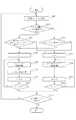
Next, the flow of printing processing in the first embodiment will be described with reference to FIG. Here, a printing process executed when a stacker is selected as a sheet discharge method in the
ステップS1001で、CPU205は、印刷ジョブの入力処理を実行する。ここで、入力処理は、コンピュータ端末233から印刷ジョブ(画像データ)を受信することにより実行される。具体的には、外部I/F202がコンピュータ端末233から印刷ジョブを受信したことにより印刷ジョブに制御コードとして含まれる画像データをハードディスク209へ書き込む。そして、メモリコントローラ部206は、ハードディスク209から印刷ジョブを読み出してプリンタ部203へ出力することで複数ページの画像データを入力する。 In step S1001, the CPU 205 executes print job input processing. Here, the input process is executed by receiving a print job (image data) from the
ステップS1002で、CPU205は、スタッカ装置104のスタッカトレイ1304にシートSが積載されているか否かを判別する。CPU205は、スタッカトレイ1304にシートSが積載されている場合はステップS1004に進み、積載されていない場合はステップS1003に進む。 In step S <b> 1002, the CPU 205 determines whether sheets S are stacked on the
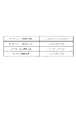
ステップS1003で、CPU205は、ステップS1001にて入力された印刷ジョブに含まれる印刷処理条件情報に基づいて、排紙モードとしてフェイスダウン排出モード又はフェイスアップ排出モードのいずれかを選択する。ここで、印刷ジョブに含まれる印刷処理条件情報とは、図14に示すような情報である。印刷処理条件情報としては、図7〜9にて、プリンタドライバ1003を介して操作者が入力した値が設定されている。また、図12は、印刷装置105のハードディスク209に記憶されているテーブルであり、オフラインシート処理の種類に対する排出モードの指定を示すものである。なお、CPU205は、ネットワーク232を介して、オフラインくるみ製本装置234及びオフライン断裁装置235から、図12のテーブルに示す情報を取得する。また、ハードディスク209に予め図12に示す情報を記憶させておいても良い。第1の実施形態においては、シートSをスタッカ装置105のスタッカトレイ1304に積載する場合に、オフラインシート処理の実行に関して以下の3種類の方法がある。1つ目は、シートSをスタッカ装置105のスタッカトレイ1304に積載するだけで、その後に何のシート処理も実行しない方法である。また、2つ目は、シートSをオフラインくるみ製本装置234にてくるみ製本処理させる方法である。3つ目は、シートSをオフライン断裁装置235にて断裁処理させる方法である。そして、図12には、各々の方法に対して、排出モードが設定されている。 In step S1003, the CPU 205 selects either the face-down discharge mode or the face-up discharge mode as the discharge mode based on the print processing condition information included in the print job input in step S1001. Here, the print processing condition information included in the print job is information as shown in FIG. As the print processing condition information, values input by the operator via the
図12では、オフラインシート処理をしない場合は、フェイスダウン排出モードが対応付けられている。フェイスダウン排出モードの場合、印刷装置105は印刷ジョブにかかる先頭ページから順に印刷処理をすることとなる。印刷装置105のCPU205は、印刷ジョブをコンピュータ端末233から受信しつつ順次印刷ジョブに含まれる制御データ(PDLデータ)を解析してプリンタ部203にて印刷可能な印刷データに変換する。なお、ここでは、印刷装置105は、印刷ジョブを受信するにあたって、先頭ページにかかるデータを先に受信し、その後に2、3、4と1ページずつ受信して最後に最終ページにかかるデータを受信するものとする。そして、印刷ジョブに複数ページの画像データが含まれている場合、CPU205は、先頭ページから順に制御データの解析を行うので、先頭ページから順に印刷データが生成される。フェイスダウン排出モードは、先頭ページから順に印刷処理するモードであるので、先頭ページの印刷データが生成され次第、すぐに印刷処理を開始できるメリットがある。 In FIG. 12, when the offline sheet processing is not performed, the face-down discharge mode is associated. In the face-down discharge mode, the
また、図12では、オフラインシート処理として、オフラインくるみ製本処理を実行する場合は、フェイスアップ排出モードが対応付けられている。フェイスアップ排出モードの場合、印刷装置105は印刷ジョブにかかる最終ページから順に印刷処理をすることとなる。フェイスアップ排出モードは、最終ページから順に印刷処理するモードであるので、最終ページの印刷データが生成されなければ、印刷処理を開始できないというデメリットがある。しかし、図2におけるオフラインくるみ製本装置234は、印刷処理された面を上向き(フェイスアップ)にてトレイ(不図示)にシート束を設置してくるみ製本処理を開始させるものとする。そうすると、スタッカ装置104のスタッカトレイ1304には、シートをフェイスアップにて積載させる必要がある。そこで、オフラインくるみ製本処理には、フェイスアップ排出モードが対応付けられているのである。 In FIG. 12, when offline case binding processing is executed as offline sheet processing, the face-up discharge mode is associated. In the face-up discharge mode, the
また、図12では、オフラインシート処理として、オフライン断裁処理を実行する場合は、フェイスダウン排出モードが対応付けられている。図2におけるオフライン断裁装置235は、印刷処理された面を下向き(フェイスダウン)にてトレイ(不図示)にシート束を設置して断裁処理を開始させるものとする。そうすると、スタッカ装置104のスタッカトレイ1304には、シートをフェイスダウンにて積載させる必要がある。そこで、オフライン断裁処理には、フェイスダウン排出モードが対応付けられているのである。 In FIG. 12, when offline cutting processing is executed as offline sheet processing, face-down discharge modes are associated with each other. The off-line cutting apparatus 235 in FIG. 2 sets a sheet bundle on a tray (not shown) with the printed surface facing downward (face down), and starts the cutting process. Then, it is necessary to stack the sheets face down on the
ここで、図10のステップS1003の説明に戻る。
図10のステップS1003で、CPU205は、図14の印刷処理条件情報にてくるみ製本処理が設定されており、図12にてくるみ製本処理はフェイスアップ排出モードに対応付けられていることから、ステップS1011へ進む。Here, the description returns to step S1003 in FIG.
In step S1003 in FIG. 10, the CPU 205 sets the case binding process in the print processing condition information in FIG. 14, and the case binding process in FIG. 12 is associated with the face-up discharge mode. The process proceeds to S1011.
ステップS1011で、CPU205は、複数ページの画像データの印刷順序を制御するためのページ識別情報Nとして、初期値の“1”を設定する。 In step S <b> 1011, the CPU 205 sets an initial value “1” as page identification information N for controlling the printing order of the image data of a plurality of pages.
CPU205は、ステップS1012で(M−N+1)ページ目の印刷処理をプリンタ部203に実行させる。ここで、(M−N+1)ページ目としているのは、Mページの印刷ジョブを印刷する場合に、最終ページであるMページ目から印刷処理させるためである。そして、フェイスアップ排出モードでは、フェイスダウン排出モードと異なりシートSの反転処理をさせない。これは、印刷処理されたシートSをスタッカトレイ1304に上面にフェイスアップ(印刷処理された面が上向きの状態)で集積させるためである。 In step S <b> 1012, the CPU 205 causes the
CPU205は、ステップ1013でページ識別情報Nをインクリメントしてステップ1014へ進む。ステップS1014でCPU205は、ページ識別情報NがM+1となったかを判定し、N=M+1であればステップS1010へ進み、そうでなければステップS1012へ戻る。ここで、Mは印刷ジョブのページ数であり、例えば10ページの画像データからなる印刷ジョブであれば10が設定される。 The CPU 205 increments the page identification information N in
CPU205は、以上のステップS1012からS1014を繰り返すことで、スタッカトレイ1304へ複数枚のシートSを集積させてシート束を生成する。なお、この場合にスタッカトレイ1304に積載されるシート束を模式的に示したものが図15である。図15は、3ページの画像データからなる印刷ジョブを実行した場合に対応し、スタッカトレイ1304にシートSがフェイスアップにて集積されている。なお、この場合印刷順序は、3ページ目が先頭となり、1ページ目が最後となる。 The CPU 205 repeats steps S1012 to S1014 described above, thereby stacking a plurality of sheets S on the
以上のステップS1011〜ステップS1014はフェイスアップ排出モードを示すものであった。次に、CPU205がステップS1003にてフェイスダウン排出モードを選択した場合に実行するステップS1005〜ステップS1009について説明する。 Steps S1011 to S1014 described above indicate the face-up discharge mode. Next, steps S1005 to S1009 executed when the CPU 205 selects the face-down discharge mode in step S1003 will be described.
なお、以下のステップS1005〜S1009は、Mページの画像データからなる印刷ジョブを1ページ目、2ページ目、・・・M−1ページ目、Mページ目と印刷処理するフローである。それに対してステップS1011〜S1014は、Mページ目、M−1ページ目・・・2ページ目、1ページ目と、印刷順序を逆順にして印刷処理するフローである。 The following steps S1005 to S1009 are a flow for printing a print job including M page image data as the first page, the second page,..., The M−1 page, and the M page. On the other hand, steps S1011 to S1014 are a flow in which the printing process is performed in the reverse order of the M page, the M-1 page, the second page, and the first page.
ステップS1005で、CPU205は、複数ページの画像データの印刷順序を制御するためのページ識別情報Nとして、初期値の“1”を設定する。なお、このページ識別情報NはRAM208へ記憶されCPU205が読み出し及び書き込みが可能な情報である。 In step S <b> 1005, the CPU 205 sets an initial value “1” as the page identification information N for controlling the printing order of the image data of a plurality of pages. The page identification information N is stored in the
CPU205は、ステップS1006でNページ目の印刷処理をプリンタ部203に実行させ、ステップS1007でシートSの反転処理をさせた後にシートSをスタッカ装置104へ排出させる。なお、シートSを反転処理させているのは、シートSの上面に印刷処理された状態(フェイスアップ)のシートSをスタッカトレイ1304に下面に印刷処理された状態(フェイスダウン)で集積させるためである。 In step S <b> 1006, the CPU 205 causes the
CPU205は、ステップ1008でページ識別情報Nに1を加算してステップ1009へ進む。ステップS1009でCPU205は、ページ識別情報NがM+1となったかを判定し、N=M+1であればステップS1010へ進み、そうでなければステップS1006へ戻る。 In step 1008, the CPU 205 adds 1 to the page identification information N and proceeds to step 1009. In step S1009, the CPU 205 determines whether the page identification information N is M + 1. If N = M + 1, the process proceeds to step S1010. Otherwise, the process returns to step S1006.
CPU205は、以上のステップS1006からS1009を繰り返すことで、スタッカトレイ1304へ複数枚のシートSを集積させてシート束を生成する。なお、この場合にスタッカトレイ1304に積載されるシート束を模式的に示したものが図16である。図16は、3ページの画像データからなる印刷ジョブを実行した場合に対応し、スタッカトレイ1304にシートSがフェイスダウン(印刷処理された面が下向きの状態)にて集積されている。なお、この場合の印刷順序は、1ページ目が先頭となり、3ページ目が最後となる。 The CPU 205 repeats the above steps S1006 to S1009, thereby stacking a plurality of sheets S on the
ステップS1010で、CPU205は、引き続き実行すべき印刷ジョブがあるか否かを判定し、印刷ジョブがあればステップS1001へ戻り、印刷ジョブがなければ処理を終了させる。 In step S1010, the CPU 205 determines whether there is a print job to be continuously executed. If there is a print job, the process returns to step S1001, and if there is no print job, the process ends.
ステップS1001へ戻った後に、CPU205は印刷ジョブの入力処理を実行し、ステップS1002へ進む。既に1つの印刷ジョブの印刷処理が終了している場合、スタッカトレイ1304にはシートSが積載されているので、ステップS1004へ進む。 After returning to step S1001, the CPU 205 executes a print job input process and proceeds to step S1002. If the printing process for one print job has already been completed, the sheet S is stacked on the
ステップS1004で、CPU205は、直前に実行された印刷ジョブの排出モードがフェイスダウン排出モードであったか否かを判定する。CPU205は直前に実行された印刷ジョブの排出モードがフェイスダウン排出モードであればステップS1005へ進み、フェイスアップ排出モードであればステップS1011へ進む。ステップS1004において、CPU205は、図12及び図15のテーブルを参照することなく、前の印刷ジョブの排出モードと同一の排出モードにて印刷処理を実行する。このようにしているのは、スタッカトレイ1304に、フェイスダウン排出方法で排出されたシート束と、フェイスアップ排出方法で排出されたシート束とが混在しないようにするためである。なお、ステップS1004でいうところの直前の印刷ジョブとは、シートの排紙方法として“スタッカ”を指定した印刷ジョブのことを示す。スタッカトレイ1304に積載されるシートの排出状態(フェイスアップかフェイスダウンか)を同一にするのが目的だからである。従って、シートの排紙方法として“スタッカ”を指定する第1印刷ジョブを実行し、“中綴じ製本”を指定する第2印刷ジョブを実行し、さらに引き続いて“スタッカを指定する第3印刷ジョブを実行する場合を考える。この場合、第3印刷ジョブにとっての”直前の印刷ジョブ“とは第1印刷ジョブとなる。 In step S1004, the CPU 205 determines whether the discharge mode of the print job executed immediately before is the face-down discharge mode. If the discharge mode of the print job executed immediately before is the face-down discharge mode, the CPU 205 proceeds to step S1005, and if it is the face-up discharge mode, the CPU 205 proceeds to step S1011. In step S1004, the CPU 205 executes print processing in the same discharge mode as the previous print job discharge mode without referring to the tables of FIGS. This is because the sheet bundle discharged by the face-down discharge method and the sheet bundle discharged by the face-up discharge method are not mixed in the
<製本処理の実行手順−両面印刷>
次に、図11を用いて、第1の実施形態における印刷処理のフローを説明する。ここでは、図9のボックス904にて、シートの排紙方法としてスタッカが選択された場合に実行される印刷処理について説明する。また、図11は、図9のボックス901にてシートSの両面に印刷処理をすると設定された場合の動作を示すものである。<Bookbinding Processing Procedure-Duplex Printing>
Next, the flow of printing processing in the first embodiment will be described with reference to FIG. Here, a printing process executed when a stacker is selected as a sheet discharge method in the
なお、図11のステップS1101〜1104及びS1119は、図10のステップS1001〜1004及びS1010と同様であるので説明を省略する。 Note that steps S1101 to 1104 and S1119 in FIG. 11 are the same as steps S1001 to 1004 and S1010 in FIG.
また、以下のステップS1105〜S1111は、Mページの画像データからなる印刷ジョブを1ページ目、・・・Mページ目と印刷処理するフローである。それに対してステップS1112〜S1118は、Mページ目、・・・1ページ目と、印刷順序を逆順にして印刷処理するフローである。なお、図11ではシートSの両面に印刷処理するので、1ページ目、2ページ目、3ページ目・・・と、ページを1ずつ順番に印刷処理する方法とは異なる。 Also, the following steps S1105 to S1111 are a flow for performing print processing of a print job including M page image data as the first page,... M page. On the other hand, steps S1112 to S1118 are a flow for performing the printing process by reversing the printing order from the Mth page to the first page. In FIG. 11, since printing is performed on both sides of the sheet S, the first page, the second page, the third page,... Are different from the method in which the pages are sequentially printed one by one.
ステップS1105で、CPU205は、ページ識別情報Nとして、初期値の“1”を設定する。 In step S <b> 1105, the CPU 205 sets the initial value “1” as the page identification information N.
ステップS1106で、CPU205は、ページ識別情報NがM以下であるかを判定し、M以下であればステップS1107へ進み、そうでなければステップS1108へ進む。 In step S1106, the CPU 205 determines whether the page identification information N is equal to or less than M. If the page identification information N is equal to or less than M, the process proceeds to step S1107. Otherwise, the process proceeds to step S1108.
ステップS1107で、CPU205は、カセットからシートSを給紙させ、そのシートSにNページ目の印刷処理を実行する。 In step S <b> 1107, the CPU 205 feeds the sheet S from the cassette, and executes printing processing for the Nth page on the sheet S.
ステップS1108で、CPU205は、N−3が0より大きいか否かを判定し、大きければステップS1109へ進み、そうでなければステップS1110へ進む。ステップS1109で、CPU205は、再給紙搬送路332から搬送されるシートSに(N−3)ページ目の印刷処理を実行する。ここで、“3”は印刷装置105が装置内に保持することができるシートSの枚数を示す。印刷装置105は、両面印刷を行うにあたって、カセットからシートSを3枚連続して給紙して印刷処理を実行する。その後は、再給紙搬送路332から搬送されるシートSに対する偶数ページの印刷処理と、カセットから給紙したシートSに対する奇数ページの印刷処理を交互に繰り返す。この繰り返しの印刷処理により、シートSの両面に印刷処理を行う。 In step S1108, the CPU 205 determines whether N-3 is larger than 0. If it is larger, the process proceeds to step S1109. Otherwise, the process proceeds to step S1110. In step S1109, the CPU 205 executes the printing process for the (N-3) th page on the sheet S conveyed from the refeed
ステップS1110で、CPU205はNに2を加算してステップS1111へ進む。ステップS1111で、CPU205は、ページ識別情報NがM+5となったかを判定し、N=M+5であればステップS1119へ進み、そうでなければステップS1106へ戻る。 In step S1110, the CPU 205 adds 2 to N and proceeds to step S1111. In step S1111, the CPU 205 determines whether the page identification information N is M + 5. If N = M + 5, the process proceeds to step S1119; otherwise, the process returns to step S1106.
ここで、S1105〜S1111においてCPU205がプリンタ部203に実行させる印刷処理における印刷順序について、印刷ジョブが10ページの画像データからなるものとして説明する。なお、カセットとしてカセット311が選択されているものとして説明する。 Here, the printing order in the printing process that the CPU 205 causes the
まず初めに、CPU205は、カセット311から3枚のシートSを給紙させ、各々に1、3、5ページ目の画像データの印刷処理を実行させる。また、CPU205は、1、3、5ページ目が印刷処理されたシートSを、再給紙搬送路332へ搬送させる。なお、再給紙搬送路332から搬送されるシートSは、印刷処理された面を下向きにして転写部325へ搬送される。 First, the CPU 205 feeds three sheets S from the
次に、CPU205は、1ページ目が印刷処理されたシートSを転写部325へ搬送させ、2ページ目の画像データの印刷処理を実行させる。その後にCPU205は、1ページ目と2ページ目の画像データの双方が印刷処理されたシートSをスタッカ装置104へ搬送させる。引き続き、CPU205は、カセット311から給紙したシートSへの7ページ目の画像データの印刷処理を実行させる。その後、CPU205は、3ページ目が印刷処理されたシートSを転写部325へ搬送させ、4ページ目の画像データの印刷処理を実行させる。次に、CPU205は、カセット311から給紙したシートSへの9ページ目の画像データの印刷処理を実行させる。引き続き、5、7及び9ページ目が印刷処理されたシートSを再給紙搬送路332から連続して転写部325へ搬送させる。そして、CPU205は、それらのシートSに6、8及び10ページ目の画像データの印刷処理を実行させる。 Next, the CPU 205 conveys the sheet S on which the first page has been printed to the
以上のように、複数ページの画像データの印刷順序は、1−3−5−2−7−4−9−6−8−10という順序になる。なお、この場合にスタッカトレイ1304に集積されるシート束を模式的に示したものが図17である。図17における数字はページ番号を模式的に示したものであり、実際には偶数に対応するページの画像がシートの上面に印刷処理されている。その一方で、奇数に対応するページの画像がシートの下面に印刷処理されている。 As described above, the printing order of the image data of a plurality of pages is the order of 1-3-5-2-7-4-9-6-8-10. In this case, FIG. 17 schematically shows sheet bundles stacked on the
次に、ステップS1104又はステップS1103にてCPU205がフェイスアップ排出モードを選択した場合に実行されるステップについて説明する。 Next, steps executed when the CPU 205 selects the face-up discharge mode in step S1104 or step S1103 will be described.
ステップS1112で、CPU205は、ページ識別情報Nとして、初期値の“1”を設定する。 In step S <b> 1112, the CPU 205 sets the initial value “1” as the page identification information N.
ステップS1113で、CPU205は、ページ識別情報NがM以下であるかを判定し、M以下であればステップS1114へ進み、そうでなければステップS1115へ進む。 In step S1113, the CPU 205 determines whether the page identification information N is equal to or less than M. If the page identification information N is equal to or less than M, the process proceeds to step S1114. Otherwise, the process proceeds to step S1115.
ステップS1114で、CPU205は、カセットからシートSを給紙させ、そのシートSに(M−N+1)ページ目の印刷処理を実行する。 In step S <b> 1114, the CPU 205 feeds the sheet S from the cassette, and executes the printing process for the (M−N + 1) th page on the sheet S.
ステップS1115で、CPU205は、N−3が0より大きいか否かを判定し、大きければステップS1116へ進み、そうでなければステップS1117へ進む。ステップS1116で、CPU205は、再給紙搬送路332から搬送されるシートSに(M−N+4)ページ目の印刷処理を実行する。その後は、再給紙搬送路332から搬送されるシートSに対する印刷処理と、カセットから給紙したシートSに対する印刷処理を交互に繰り返す。この繰り返しの印刷処理により、シートSの両面に印刷処理を行う。 In step S1115, the CPU 205 determines whether N-3 is larger than 0. If it is larger, the process proceeds to step S1116; otherwise, the process proceeds to step S1117. In step S <b> 1116, the CPU 205 executes the printing process for the (M−N + 4) th page on the sheet S conveyed from the refeed
ステップS1117で、CPU205はNに2を加算してステップS1118へ進む。ステップS1118で、CPU205は、ページ識別情報NがM+5となったかを判定し、N=M+5であればステップS1119へ進み、そうでなければステップS1113へ戻る。 In step S1117, the CPU 205 adds 2 to N and proceeds to step S1118. In step S1118, the CPU 205 determines whether the page identification information N is M + 5. If N = M + 5, the process proceeds to step S1119; otherwise, the process returns to step S1113.
ここで、S1112〜S1118においてCPU205がプリンタ部203に実行させる印刷処理における印刷順序について、印刷ジョブが10ページの画像データからなるものとして説明する。なお、カセットとしてカセット311が選択されているものとして説明する。 Here, the printing order in the printing process that the CPU 205 causes the
まず初めに、CPU205は、カセット311から3枚のシートSを給紙させ、各々に10、8、6ページ目の画像データの印刷処理を実行させる。また、CPU205は、10、8、6ページ目が印刷処理されたシートSを、再給紙搬送路332へ搬送させる。 First, the CPU 205 feeds three sheets S from the
次に、CPU205は、10ページ目が印刷処理されたシートSを転写部325へ搬送させ、9ページ目の画像データの印刷処理を実行させる。その後にCPU205は、10ページ目と9ページ目の画像データの双方が印刷処理されたシートSをスタッカ装置104へ搬送させる。引き続き、CPU205は、カセット311から給紙したシートSへの4ページ目の画像データの印刷処理を実行させる。その後、CPU205は、8ページ目が印刷処理されたシートSを転写部325へ搬送させ、7ページ目の画像データの印刷処理を実行させる。次に、CPU205は、カセット311から給紙したシートSへの2ページ目の画像データの印刷処理を実行させる。引き続き、6、4及び2ページ目が印刷処理されたシートSを再給紙搬送路332から連続して転写部325へ搬送させる。そして、CPU205は、それらのシートSに5、3及び1ページ目の画像データの印刷処理を実行させる。 Next, the CPU 205 conveys the sheet S on which the 10th page has been printed to the
以上のように、複数ページの画像データの印刷順序は、10−8−6−9−4−7−2−5−3−1という順序になる。この右開き製本モードにおける印刷順序は、左開き製本における印刷順序の逆順となっている。なお、この場合に集積トレイ42に集積されるシート束S1を模式的に示したものが図18である。図18における数字はページ番号を模式的に示したものであり、実際には奇数に対応するページの画像がシートの上面に印刷処理されている。その一方で、偶数に対応するページの画像がシートの下面に印刷処理されている。 As described above, the printing order of the image data of a plurality of pages is the order of 10-8-6-9-4-7-2-5-3-1. The printing order in the right-open bookbinding mode is the reverse of the printing order in the left-open bookbinding mode. In this case, FIG. 18 schematically shows the sheet bundle S1 stacked on the stacking tray 42. The numbers in FIG. 18 schematically indicate page numbers. In practice, an image of a page corresponding to an odd number is printed on the upper surface of the sheet. On the other hand, a page image corresponding to an even number is printed on the lower surface of the sheet.
以上説明したように、第1の実施形態によれば、印刷システム2000は、スタッカトレイ1304にシートSを反転させて排出するフェイスダウン排出モードとシートを反転させることなく排出するフェイスアップ排出モードのいずれかにてシートSを排出可能である。また、印刷システム2000は、スタッカトレイ1304に連続して排出される複数の印刷ジョブにかかるシート束の排出状態(フェイスアップ又はフェイスダウン)を同一にすることができる。 As described above, according to the first embodiment, the
なお、上記の説明においては、印刷ジョブはコンピュータ端末233から入力するものとして説明したが、他の態様であっても良い。例えば、印刷装置105が備えるスキャナ部201にて複数枚の原稿を画像データとして読み込むことで印刷ジョブを入力しても良い。この場合、図7〜9にてプリンタドライバ1003の設定を行っていたものを、操作部204を介して設定できるようにすればよい。 In the above description, the print job has been described as being input from the
(その他の実施形態)
また、本発明の目的は、前述した実施形態の機能を実現するソフトウェアのプログラムコードを記録した記憶媒体を、システムあるいは装置に供給することによっても達成される。この場合、そのシステムあるいは装置のコンピュータが記憶媒体に格納されたプログラムコードを読み出し実行すること前述した実施形態の機能を実現する。この場合、記憶媒体から読み出されたプログラムコード自体が前述した実施形態の機能を実現することになり、そのプログラムコードを記憶した記憶媒体は本発明を構成することになる。(Other embodiments)
The object of the present invention can also be achieved by supplying a storage medium storing software program codes for realizing the functions of the above-described embodiments to a system or apparatus. In this case, the function of the above-described embodiment is realized by reading and executing the program code stored in the storage medium by the computer of the system or apparatus. In this case, the program code itself read from the storage medium realizes the functions of the above-described embodiment, and the storage medium storing the program code constitutes the present invention.
101 断裁装置
102 中綴じ製本装置
103 くるみ製本装置
104 スタッカ装置
105 印刷装置
201 スキャナ部
203 プリンタ部
250 原稿給送ユニット
311〜315 カセット
332 再給紙搬送路
1304 スタッカトレイ
1308 シート検知センサ
2000 印刷システム
S シート
DESCRIPTION OF
Claims (7)
Translated fromJapanese前記入力手段により入力された印刷ジョブに基づいて、複数のシートに印刷処理する印刷手段と、
前記印刷手段により印刷処理された複数のシートをシート束として積載する積載手段と、
前記シート束にかかるシートを、前記積載手段に積載される前に反転させる反転手段と、
前記シート束にかかるシートを前記反転手段により反転処理させて前記積載手段に排出する第1の排出モードと、前記シート束にかかるシートを前記反転手段により反転処理させることなく前記積載手段に排出する第2の排出モードのいずれかのモードを選択する選択手段とを有し、
前記選択手段は、前記第1の印刷ジョブに引き続き第2の印刷ジョブに基づいて印刷処理を実行する場合、前記第1の印刷ジョブにかかるシート束の排出のために選択した排出モードを、前記第2の印刷ジョブにかかるシート束の排出のために選択することを特徴とする印刷装置。An input means for inputting a print job including image data of a plurality of pages;
Printing means for printing on a plurality of sheets based on the print job input by the input means;
Stacking means for stacking a plurality of sheets printed by the printing means as a sheet bundle;
Reversing means for reversing the sheets of the sheet bundle before being stacked on the stacking means;
A first discharge mode in which the sheet on the sheet bundle is reversed by the reversing unit and discharged to the stacking unit, and the sheet on the sheet bundle is discharged to the stacking unit without being reversed by the reversing unit. Selecting means for selecting any one of the second discharge modes;
When the selection unit executes a printing process based on a second print job subsequent to the first print job, the selection unit selects a discharge mode selected for discharging the sheet bundle related to the first print job. A printing apparatus selected for discharging a sheet bundle relating to a second print job.
前記第1の印刷ジョブは前記検知手段が前記積載手段にシートが積載されていないと検知している状態で入力される印刷ジョブであり、
前記選択手段は、前記検知手段が前記積載手段にシートが積載されていないと検知するまでは、前記第1の印刷ジョブにかかるシート束の排出のために選択した排出モードを、前記第1の印刷ジョブに引き続き入力される全ての印刷ジョブにかかるシート束の排出のために選択することを特徴とする請求項1に記載の印刷装置。Detecting means for detecting whether or not sheets are stacked on the stacking means;
The first print job is a print job that is input in a state where the detection unit detects that a sheet is not stacked on the stacking unit.
The selection unit selects the discharge mode selected for discharging the sheet bundle relating to the first print job until the detection unit detects that no sheet is stacked on the stacking unit. 2. The printing apparatus according to claim 1, wherein selection is made for discharging a sheet bundle relating to all the print jobs input subsequently to the print job.
前記選択手段は、前記取得手段が取得した情報に基づいて、前記第1の排出モードと前記第2の排出モードのいずれかを選択することを特徴とする請求項1又は2に記載の印刷装置。Obtaining means for obtaining information relating to a sheet processing apparatus that executes sheet processing using a sheet bundle printed by the printing apparatus;
The printing apparatus according to claim 1, wherein the selection unit selects one of the first discharge mode and the second discharge mode based on information acquired by the acquisition unit. .
前記取得手段は、前記通信媒体を介して前記シート処理装置から前記シート処理装置にかかる情報を取得することを特徴とする請求項3に記載の印刷装置。The sheet processing apparatus is connected to the printing apparatus via a communication medium,
The printing apparatus according to claim 3, wherein the acquisition unit acquires information on the sheet processing apparatus from the sheet processing apparatus via the communication medium.
前記入力工程により入力された印刷ジョブに基づいて、複数のシートに印刷処理する印刷手段と、
前記シート束にかかるシートを、反転させる反転工程と、
前記シート束にかかるシートを前記反転工程により反転処理させて前記積載部に排出する第1の排出モードと、前記シート束にかかるシートを前記反転工程により反転処理させることなく前記積載部に排出する第2の排出モードのいずれかのモードを選択する選択工程と、
前記印刷工程により印刷処理された複数のシートを前記選択工程にて選択した排出モードにて排出させて積載部に積載する積載工程とを有し、
前記選択工程は、前記第1の印刷ジョブに引き続き第2の印刷ジョブに基づいて印刷処理を実行する場合、前記第1の印刷ジョブにかかるシート束の排出のために選択した排出モードを、前記第2の印刷ジョブにかかるシート束の排出のために選択することを特徴とする印刷方法。
An input process for inputting a print job including image data of a plurality of pages;
Printing means for performing printing processing on a plurality of sheets based on the print job input in the input step;
A reversing step of reversing the sheets in the sheet bundle;
A first discharge mode for reversing the sheets on the sheet bundle by the reversing step and discharging the sheets to the stacking unit; and discharging the sheets on the sheet bundle to the stacking unit without performing reversal processing by the reversing step. A selection step of selecting any one of the second discharge modes;
A stacking step of discharging a plurality of sheets printed by the printing step in a discharge mode selected in the selection step and stacking the stacked sheets on a stacking unit;
In the selection step, when a print process is executed based on a second print job following the first print job, the discharge mode selected for discharging the sheet bundle related to the first print job is set to A printing method comprising selecting for discharging a sheet bundle relating to a second print job.
Priority Applications (2)
| Application Number | Priority Date | Filing Date | Title |
|---|---|---|---|
| JP2006020971AJP2007197206A (en) | 2006-01-30 | 2006-01-30 | Printing apparatus and printing method |
| US11/622,362US7924445B2 (en) | 2006-01-30 | 2007-01-11 | Printing apparatus and printing method |
Applications Claiming Priority (1)
| Application Number | Priority Date | Filing Date | Title |
|---|---|---|---|
| JP2006020971AJP2007197206A (en) | 2006-01-30 | 2006-01-30 | Printing apparatus and printing method |
Publications (1)
| Publication Number | Publication Date |
|---|---|
| JP2007197206Atrue JP2007197206A (en) | 2007-08-09 |
Family
ID=38321775
Family Applications (1)
| Application Number | Title | Priority Date | Filing Date |
|---|---|---|---|
| JP2006020971APendingJP2007197206A (en) | 2006-01-30 | 2006-01-30 | Printing apparatus and printing method |
Country Status (2)
| Country | Link |
|---|---|
| US (1) | US7924445B2 (en) |
| JP (1) | JP2007197206A (en) |
Cited By (1)
| Publication number | Priority date | Publication date | Assignee | Title |
|---|---|---|---|---|
| KR101943150B1 (en) | 2014-12-25 | 2019-01-28 | 캐논 가부시끼가이샤 | Print apparatus, method for controlling print apparatus, and storage medium |
Families Citing this family (4)
| Publication number | Priority date | Publication date | Assignee | Title |
|---|---|---|---|---|
| JP4513037B2 (en)* | 2008-04-28 | 2010-07-28 | ブラザー工業株式会社 | Printing system and printer driver |
| JP2012037928A (en)* | 2010-08-03 | 2012-02-23 | Canon Inc | Information processor, image forming device, control method thereof, and program |
| JP2017156832A (en)* | 2016-02-29 | 2017-09-07 | 富士ゼロックス株式会社 | Print control program and information processing device |
| JP2024061377A (en)* | 2022-10-21 | 2024-05-07 | キヤノン株式会社 | Control program, information processing device, printer and control method |
Family Cites Families (21)
| Publication number | Priority date | Publication date | Assignee | Title |
|---|---|---|---|---|
| JPH08278728A (en)* | 1995-04-10 | 1996-10-22 | Ricoh Co Ltd | Image forming device |
| JP3935252B2 (en)* | 1997-12-26 | 2007-06-20 | キヤノン株式会社 | Image forming apparatus and job processing method |
| JP3937666B2 (en)* | 1999-11-02 | 2007-06-27 | キヤノン株式会社 | Printing control method and apparatus |
| US6169873B1 (en)* | 1999-12-15 | 2001-01-02 | Hewlett-Packard Company | Automated face up and down detection of image information |
| JP2001175440A (en)* | 1999-12-20 | 2001-06-29 | Canon Inc | Data processing device, image recording device, control method of data processing device, control method of image recording device, and storage medium |
| JP2001205864A (en)* | 2000-01-27 | 2001-07-31 | Canon Inc | Image processing apparatus and method, and program storage medium |
| US6350072B1 (en)* | 2000-02-24 | 2002-02-26 | Xerox Corporation | Printer with plural mode integral module for document handling print output and print duplex inversion |
| US6397023B1 (en)* | 2000-06-06 | 2002-05-28 | Hewlett-Packard Company | Techniques for achieving correct order in printer output |
| US6671472B2 (en)* | 2001-03-15 | 2003-12-30 | Canon Kabushiki Kaisha | Image forming apparatus, control method thereof and control program therefor |
| JP5147152B2 (en)* | 2001-08-06 | 2013-02-20 | キヤノン株式会社 | Duplex printing device |
| JP3950727B2 (en)* | 2002-04-10 | 2007-08-01 | キヤノン株式会社 | Discharge processing apparatus and image forming apparatus |
| US20040156064A1 (en)* | 2003-02-07 | 2004-08-12 | Kevin Owen | Printing methods and apparatus |
| JP4532989B2 (en)* | 2003-06-12 | 2010-08-25 | キヤノン株式会社 | Image forming apparatus |
| JP2005121716A (en) | 2003-10-14 | 2005-05-12 | Canon Inc | Image forming apparatus, control method thereof, and program |
| JP3814626B2 (en)* | 2004-04-05 | 2006-08-30 | キヤノン株式会社 | Image forming system, control method, storage medium, program, and image forming apparatus |
| US6980767B1 (en)* | 2004-11-11 | 2005-12-27 | Lexmark International, Inc. | Method and apparatus for adhering sheets of print media together by use of toner in an electrophotographic printer |
| US7546056B2 (en)* | 2004-12-22 | 2009-06-09 | Canon Kabushiki Kaisha | Printing apparatus and method performing either automatic or manual duplex printing based on copy media attributes |
| JP4708993B2 (en)* | 2005-01-14 | 2011-06-22 | キヤノン株式会社 | Printing system, control method, and program |
| JP5031346B2 (en)* | 2006-01-20 | 2012-09-19 | キヤノン株式会社 | Printing system, job processing method, computer program |
| US7904015B2 (en)* | 2006-12-15 | 2011-03-08 | Xerox Corporation | Cut sheet media handling transport |
| JP4912166B2 (en)* | 2007-01-24 | 2012-04-11 | キヤノン株式会社 | Printing system and control method thereof |
- 2006
- 2006-01-30JPJP2006020971Apatent/JP2007197206A/enactivePending
- 2007
- 2007-01-11USUS11/622,362patent/US7924445B2/ennot_activeExpired - Fee Related
Cited By (1)
| Publication number | Priority date | Publication date | Assignee | Title |
|---|---|---|---|---|
| KR101943150B1 (en) | 2014-12-25 | 2019-01-28 | 캐논 가부시끼가이샤 | Print apparatus, method for controlling print apparatus, and storage medium |
Also Published As
| Publication number | Publication date |
|---|---|
| US20070177176A1 (en) | 2007-08-02 |
| US7924445B2 (en) | 2011-04-12 |
Similar Documents
| Publication | Publication Date | Title |
|---|---|---|
| JP5554982B2 (en) | Printing control apparatus, printing apparatus control method, and program | |
| JP5078496B2 (en) | Image forming apparatus, control method, and control program | |
| JP5435968B2 (en) | Sheet processing apparatus, sheet processing apparatus control method, storage medium, and program | |
| JP5538687B2 (en) | Sheet stacking apparatus, sheet stacking apparatus control method, and program | |
| JP5294656B2 (en) | Printing system, control method thereof, and program | |
| US9016680B2 (en) | Sheet processing apparatus, control method of sheet processing apparatus, and program | |
| JP5489481B2 (en) | Print control apparatus, print control method, and program | |
| JP2009249106A (en) | Printing device, controlling method of printing device, and recording medium and program | |
| JP5335533B2 (en) | Printing apparatus, printing apparatus control method, and program | |
| JP5328337B2 (en) | Image forming apparatus, image forming system, control method for image forming apparatus, and program | |
| JP4868814B2 (en) | Printing apparatus, printing method, and printing program | |
| JP5538755B2 (en) | Printing apparatus, printing apparatus control method, and program | |
| JP2007197206A (en) | Printing apparatus and printing method | |
| JP4684929B2 (en) | Post-processing apparatus and image forming system | |
| EP2465798B1 (en) | Sheet processing apparatus and method, as well as controlling apparatus | |
| JP5328963B2 (en) | Image forming apparatus, control method, and control program | |
| JP6077829B2 (en) | Sheet processing apparatus, control method thereof, and program | |
| US8976394B2 (en) | Printing system and control method using first and second user interfaces | |
| JP5791667B2 (en) | Image forming apparatus, control method, and control program | |
| JP2017042940A (en) | Image processing apparatus, information processing apparatus, information processing method, and program | |
| JP2007156903A (en) | Printing system and control method therefor, computer program, and storage medium | |
| JP2005088375A (en) | Printing device | |
| JP6761451B2 (en) | Printing equipment and its control method | |
| JP5615413B2 (en) | Image forming apparatus, image forming system, control method for image forming apparatus, and program |
Legal Events
| Date | Code | Title | Description |
|---|---|---|---|
| A977 | Report on retrieval | Free format text:JAPANESE INTERMEDIATE CODE: A971007 Effective date:20080905 | |
| A131 | Notification of reasons for refusal | Free format text:JAPANESE INTERMEDIATE CODE: A131 Effective date:20080909 | |
| A02 | Decision of refusal | Free format text:JAPANESE INTERMEDIATE CODE: A02 Effective date:20090120 |