JP2007185723A - Automatic alignment device and method - Google Patents
Automatic alignment device and methodDownload PDFInfo
- Publication number
- JP2007185723A JP2007185723AJP2006003937AJP2006003937AJP2007185723AJP 2007185723 AJP2007185723 AJP 2007185723AJP 2006003937 AJP2006003937 AJP 2006003937AJP 2006003937 AJP2006003937 AJP 2006003937AJP 2007185723 AJP2007185723 AJP 2007185723A
- Authority
- JP
- Japan
- Prior art keywords
- workpiece
- cathode
- electrode rod
- central axis
- robot
- Prior art date
- Legal status (The legal status is an assumption and is not a legal conclusion. Google has not performed a legal analysis and makes no representation as to the accuracy of the status listed.)
- Pending
Links
Images


Landscapes
- Automatic Assembly (AREA)
- Manipulator (AREA)
Abstract
Translated fromJapaneseDescription
Translated fromJapanese本発明は、複数のワークの中心軸を自動的に合せる自動調芯装置及び方法に関する。 The present invention relates to an automatic alignment apparatus and method for automatically aligning central axes of a plurality of workpieces.
ツールを交換して様々な作業に使用することができる汎用性を備えた産業用ロボットとして、多関節ロボットが知られている。この多関節ロボットには、アームを主に水平方向で移動させる水平多関節ロボット(スカラーロボット)や、アームを主に垂直方向で移動させる垂直多関節ロボット(多軸ロボット)等がある。多軸ロボットは、ツールを任意の姿勢にすることができ、スカラーロボットに比べ、より高い汎用性を備えている。 Articulated robots are known as industrial robots with versatility that can be used for various tasks by exchanging tools. The articulated robot includes a horizontal articulated robot (scalar robot) that moves an arm mainly in a horizontal direction, and a vertical articulated robot (multi-axis robot) that moves an arm mainly in a vertical direction. A multi-axis robot can have a tool in an arbitrary posture and has higher versatility than a scalar robot.
多関節ロボットに所定の動作を行なわせるために、撮像カメラと画像認識装置とからなる視覚センサでワークの位置や姿勢を検出し、この検出位置にロボットハンド等のツールを移動させて、ワークをハンドリングする手法が一般に用いられている。視覚センサで検出した位置にツールを精度よく移動させるには、視覚センサの検出位置座標系と、多関節ロボットのツール位置座標系とを高精度に対応させなければならない。この二つの座標系を対応させる作業は、一般にキャリブレーションと呼ばれている。 In order to cause the articulated robot to perform a predetermined operation, the position and posture of the workpiece are detected by a visual sensor composed of an imaging camera and an image recognition device, and a tool such as a robot hand is moved to this detection position to move the workpiece. A handling method is generally used. In order to accurately move the tool to the position detected by the visual sensor, the detection position coordinate system of the visual sensor and the tool position coordinate system of the articulated robot must be associated with high accuracy. The operation of making these two coordinate systems correspond is generally called calibration.
また、キャリブレーションを行っただけでは多関節ロボットを正確に動作させることができない。多関節ロボットを稼働させる前に基準となるワークの位置や、この基準となるワークに作業を行う際のツールの基準姿勢等を教えるティーチングが必要となる。そして、実際に多関節ロボットが稼働する際には、視覚センサによってワークの位置を検出し、このワークの検出位置をティーチングされた基準となるワークの位置と比較して差を求め、この差の分だけツールの基準姿勢をオフセットすることにより作業を行う。 In addition, the articulated robot cannot be operated accurately only by performing calibration. Prior to operating the multi-joint robot, teaching is required to teach the position of the reference workpiece, the reference posture of the tool when working on the reference workpiece, and the like. When the articulated robot actually operates, the position of the workpiece is detected by a visual sensor, and the difference between the detected position of the workpiece and the reference workpiece position that has been taught is obtained. Work by offsetting the reference posture of the tool by that amount.
従来のティーチングは、オペレータが多関節ロボットのツールを手で持って基準姿勢の位置に移動させたり、ティーチングペンダントと呼ばれるリモコンで多関節ロボットのアームを動かしてツールを基準姿勢に移動させ、その位置で基準姿勢と基準位置とを登録している。
しかし、上述した従来のティーチング方法では、ワークの基準位置とツールの基準姿勢との中心軸を合せること、いわゆる芯合せ作業(調芯作業)が非常に難しく、時間がかかるという問題があった。また、オペレータによる作業であるため、オペレータの能力によって精度に差が出てしまうという問題もある。 However, the above-described conventional teaching method has a problem that it is very difficult and time-consuming to align the center axes of the workpiece reference position and the tool reference posture, that is, so-called centering work (alignment work). In addition, since the operation is performed by the operator, there is a problem that the accuracy varies depending on the ability of the operator.
本発明は、上記課題を解決するためのもので、ティーチング時の調芯作業を短時間で精度良く行うことができる自動調芯装置及び方法を提供する。 The present invention is for solving the above-described problems, and provides an automatic alignment apparatus and method capable of performing alignment work during teaching with high accuracy in a short time.
上記課題を解決するために、本発明の自動調芯装置は、第1のワークが保持される保持手段と、第1のワークの中心軸ベクトルとその位置とを検出する検出手段と、第2のワークを保持し、検出手段の検出結果に基づいて移動して第1のワークに第2のワークを取り付ける可動アクチュエータとを有する組立装置に用いられ、可動アクチュエータを制御して第2のワークを検出手段の検出範囲内に移動させ、検出手段を制御して第1のワークの中心軸ベクトルおよびその位置と第2のワークの中心軸ベクトルおよびその位置とを検出させる制御手段と、検出手段の検出結果から、第1のワークの中心軸と第2のワークの中心軸との成す角およびその間隔が所定の範囲内にあるか否かを判定する判定手段と、第1のワークの中心軸と第2のワークの中心軸との成す角およびその間隔が所定の範囲内に無いときに、その誤差量を算出する演算手段とを備えており、制御手段は、第1のワークの中心軸ベクトルと第2のワークの中心軸ベクトルとの間隔が所定の範囲内に収まるまで、演算手段で算出された誤差量の分だけ第2のワークを移動させ、第1のワークの中心軸ベクトルおよびその位置と第2のワークの中心軸ベクトルおよびその位置とを検出させる動作を繰り返すようにしたものである。 In order to solve the above-described problems, an automatic alignment device of the present invention includes a holding unit that holds a first workpiece, a detection unit that detects a center axis vector of the first workpiece and a position thereof, and a second unit. Is used in an assembling apparatus having a movable actuator that moves based on the detection result of the detection means and attaches the second workpiece to the first workpiece. The second workpiece is controlled by controlling the movable actuator. Control means for moving the detection means within a detection range and controlling the detection means to detect the central axis vector of the first workpiece and its position and the central axis vector of the second workpiece and its position; A determination means for determining whether or not an angle formed by the central axis of the first workpiece and the central axis of the second workpiece and the interval thereof are within a predetermined range from the detection result; and the central axis of the first workpiece And the second word And an arithmetic means for calculating an error amount when the angle formed by the central axis and the distance between the central axis and the central axis are not within a predetermined range. The control means includes a central axis vector of the first workpiece and a second axis The second workpiece is moved by the amount of error calculated by the computing means until the interval with the center axis vector of the workpiece falls within a predetermined range, and the center axis vector of the first workpiece, its position, and the second The operation of detecting the center axis vector of the workpiece and its position is repeated.
また、検出手段として、視覚センサを用いたものである。更に、視覚センサとして、第1のワークと第2のワークとを異なる方向から撮像する第1の撮像手段と第2の撮像手段とを有するものである。また、第1の撮像手段は、第1、及び第2のワークを側方から撮像し、第2の撮像手段は、第2の撮像手段と直交する方向から該第1及び第2のワークの側方を撮像するようにしたものである。 Further, a visual sensor is used as the detection means. Further, the visual sensor includes a first imaging means and a second imaging means for imaging the first workpiece and the second workpiece from different directions. The first imaging means images the first and second workpieces from the side, and the second imaging means takes the first and second workpieces from a direction orthogonal to the second imaging means. The side is imaged.
また、可動アクチュエータとして、2軸以上、6軸以下の可動軸を有する多関節ロボットを用いたものである。 Further, as the movable actuator, an articulated robot having movable axes of 2 axes or more and 6 axes or less is used.
更に、第1のワークとして、キセノン管の電極棒を用い、第2のワークとして、電極棒に挿入されてかしめられるカソードを用いたものである。 Furthermore, a xenon tube electrode rod is used as the first workpiece, and a cathode inserted into the electrode rod and caulked is used as the second workpiece.
また、本発明の自動調芯方法は、第1のワークが保持される保持手段と、第1のワークの中心軸ベクトルとその位置とを検出する検出手段と、第2のワークを保持し、検出手段の検出結果に基づいて移動して第1のワークに第2のワークを取り付ける可動アクチュエータとを備える組立装置に用いられ、可動アクチュエータを制御して、第2のワークを検出手段の検出範囲内に移動させる第1のステップと、検出手段を制御して、第1のワークと第2のワークとの中心軸ベクトルとその位置とを検出させる第2のステップと、この検出結果から第1のワークの中心軸と第2のワークの中心軸との成す角およびその間隔が所定の範囲内にあるか否かを判定する第3のステップと、第1のワークの中心軸と第2のワークの中心軸との成す角およびその間隔が所定の範囲内に無いときに、その誤差量を算出する第4のステップと、この誤差量の分だけ第2のワークを移動させる第5のステップとを備え、第1のワークの中心軸と第2のワークの中心軸との成す角およびその間隔が所定の範囲内に収まるまで第2〜第5のステップを繰り返すようにしている。 The automatic alignment method of the present invention includes a holding unit that holds the first workpiece, a detection unit that detects a center axis vector of the first workpiece and its position, and a second workpiece. Used in an assembling apparatus including a movable actuator that moves based on the detection result of the detection means and attaches the second work to the first work, and controls the movable actuator so that the second work is detected by the detection means. A first step of moving the first workpiece inward, a second step of controlling the detection means to detect the center axis vector and the position of the first workpiece and the second workpiece, and a first result from the detection result. A third step of determining whether or not an angle formed by the central axis of the workpiece and the central axis of the second workpiece and the interval thereof are within a predetermined range; the central axis of the first workpiece; The angle formed with the center axis of the workpiece and When the interval is not within the predetermined range, a fourth step for calculating the error amount and a fifth step for moving the second workpiece by the error amount are provided. The second to fifth steps are repeated until the angle formed by the central axis and the central axis of the second workpiece and the interval thereof are within a predetermined range.
本発明によれば、第1のワークの中心軸と第2のワークの中心軸との成す角およびその間隔を自動的に所定の範囲内に収めることができるので、ロボットのティーチング時の調芯作業が精度よく、短時間で行うことができる。また、自動的に行われるので、オペレータによる作業の忘れや、作業ミスも発生しない。 According to the present invention, the angle formed by the center axis of the first workpiece and the center axis of the second workpiece and the distance between them can be automatically within a predetermined range. Work can be performed accurately and in a short time. Moreover, since it is performed automatically, the operator forgets the work and does not cause a work mistake.
図1及び図2は、本発明の自動調芯方法及び装置を用いた挿入・かしめ装置の構成を示す外観斜視図である。この挿入・かしめ装置2は、キセノン管の陰極側電極棒にカソードを挿入し、このカソードをかしめて陰極側電極棒に固着させる装置である。 1 and 2 are external perspective views showing the configuration of an insertion / caulking apparatus using the automatic alignment method and apparatus of the present invention. The insertion / caulking device 2 is a device for inserting a cathode into a cathode side electrode rod of a xenon tube and caulking the cathode to fix it to the cathode side electrode rod.
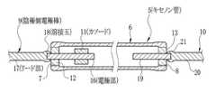
図3及び図4の断面図及び分解斜視図に示すように、ストロボ装置の光源として用いられるキセノン管5は、筒状の透明なガラス管6と、このガラス管6の両端に形成された開口部7,8に挿入される陰極側電極棒9及び陽極側電極棒10と、陰極側電極棒9に取り付けられるカソード11と、ガラス管6の開口部7,8を密封するガラスビーズ12,13と、ガラス管6内に封入されるキセノンガスから構成されている。 3 and 4, the xenon tube 5 used as the light source of the strobe device includes a cylindrical
陰極側電極棒9は、ガラス管6内に納められる電極部16と、ガラス管6外に突出されてプリント基板等への配線に使用されるリード部17とからなり、電極部16とリード部17との間には、略ボール形状の溶接玉18が設けられている。電極部16は、例えばタングステン(W)を用いて棒状に形成されている。リード部17は、例えばニッケル(Ni)を用いて形成されており、電極部16と径が同等、もしくは若干太くされている。溶接玉18は、電極部16とリード部17とを溶接して接合する際に、リード部17が溶けて電極部16の端部を包み込むことで形成される。陽極側電極棒10は、陰極側電極棒9と同様に、電極部19,リード部20,溶接玉21からなり、電極部19の長さが異なる以外は、同じ材質、同様の製造方法で製造される。 The cathode
ガラスビーズ12,13は、ガラスで略リング形状に形成されており、中央には電極棒9,10の電極部16,19が挿通される穴12a,13aが形成されている。このガラスビーズ12,13は、電極部16,19に挿入後、ヒーターで加熱されて電極棒9,10に溶着される。その後、ガラス管6の開口部7,8に挿入されてヒーターで加熱されることで溶融し、ガラス管6を密封する。 The
カソード11は、金属粉末を筒状に成型,焼結したものにセシウム化合物等を添加処理したもので、放電時の電子放出効率を高めるために用いられている。このカソード11は、ガラスビーズ12が溶着された後で電極部16の所定の位置に挿入され、外側からかしめられることにより電極部16に固着される。 The
挿入・かしめ装置2は、架台30の上部台板30aに設置されて加工を行う加工部32と、下部台板30bに設置されて加工部32を制御するハードウェアである制御部33と、この制御部33をソフトウェア的に制御する制御コンピュータ34とから構成されている。上部台板30aの側縁には、挿入・かしめ装置2の操作に用いられる各種スイッチやモニタを備えた操作盤35が設けられている。 The insertion / caulking device 2 includes a processing unit 32 that is installed on the
加工部32には、陰極側電極棒(以下、電極棒と省略する)9を供給する電極棒供給台39と、カソード11が取り付けられた電極棒9(以下、加工済み電極棒と呼ぶ)を集積する電極棒集積台41とが並んで配置されている。電極棒供給台39及び電極棒集積台41は、上面に設けられた多数の穴に電極棒9のリード部17を挿入させ、立てた状態で収納する。また、電極棒供給台39から取り出された電極棒9を保持して本かしめを行う組立台ユニット42と、この組立台ユニット42に保持された電極棒9とカソード11との位置座標と軸方向のベクトルとを検出するために撮像する第1電極棒認識カメラ43、第2電極棒認識カメラ44とが設けられている。 The processing section 32 includes an electrode
更に、組立台ユニット42の側方には、カソード11が供給されるカソード供給ユニット47が配置されている。また、電極棒供給台39から電極棒9を取り出して組立台ユニット42にセットし、カソード供給ユニット47からカソード11を取り出して組立台ユニット42の電極棒9に挿入して仮かしめを行ない、加工済み電極棒を組立台ユニット42から取り出して電極棒集積台41に集積するスカラーロボット48が設置されている。 Further, a
制御部33は、スカラーロボット48と、組立台ユニット42のロボシリンダとを制御するロボットコントローラ51と、ロボット以外を制御する多数の制御基板が組み込まれたコントロールボックス52とが設置されている。制御コンピュータ34は、このロボットコントローラ51とコントロールボックス52に接続されている。なお、下部台板30bには、カソード供給ユニット47を構成するカソード認識カメラ53も設置されている。 The controller 33 is provided with a robot controller 51 for controlling the scalar robot 48, the ROBO Cylinder of the assembly table unit 42, and a
図5は、組立台ユニット42の断面図である。組立台ユニット42は、上部台板30aに取り付けられる組立台本体55と、この組立台本体55の上部に取り付けられて電極棒9を保持する略円筒形状の組立台56と、電極棒9に仮かしめされたカソード11の外周を更に強く押圧してかしめる本かしめチャック57と、カソード11の高さ位置に合せて本かしめチャック57を昇降させるロボシリンダ58等から構成されてユニット化されており、品種変更の際には、このユニット42ごと交換することで迅速に対応することができる。 FIG. 5 is a cross-sectional view of the assembly table unit 42. The assembly base unit 42 includes an
組立台56の断面を表す図6に示すように、組立台56の上面中央には、溶接玉18よりも大きな径を有する円形の開口部56aが設けられ、その下方には、電極棒9のリード部17よりも径が大きく、かつ溶接玉18より小さな径を有する支持穴56bが形成されている。開口部56aと支持穴56bとの間は、テーパー面56cによって接続されている。 As shown in FIG. 6 showing a cross section of the assembly table 56, a
スカラーロボット48は、電極棒供給台39から1本の電極棒9を取り出して組立台ユニット42の上方に移動し、電極棒9のリード部17を組立台56の開口部56aに挿入する。組立台56に挿入された電極棒9は、リード部17が支持穴56bに収容され、溶接玉18がテーパー面56cに引っ掛かることにより、簡易に位置決めされて電極部16が組立台56の上方に突出される。なお、詳しくは図示しないが、支持穴56bに接続された通気穴56eにはエアポンプが接続されており、組立台56への電極棒9の挿入及び取り出しを空気の流れによってアシストする。 The scalar robot 48 takes out one
組立台ユニット42の周囲には、組立台56に保持された電極棒9とカソード11の中心軸ベクトルとその位置を検出するために撮像する第1電極棒認識カメラ43、第2電極棒認識カメラ44が設けられている。組立台56を挟んでこれらのカメラ43,44に正対する位置には、各カメラ43,44に対応して電極棒9とカソード11とを照明する第1電極棒照明62,第2電極棒照明63とが配置されている。これらのカメラ43,44及び照明62,63は、上部台板30aに取り付けられたブラケットによって保持されている。なお、図5に示す第2電極棒認識カメラ44及び第2電極棒照明63は、組立台ユニット42の断面方向と正確には合致していないが、第2電極棒認識カメラ44及び第2電極棒照明63による電極棒9とカソード11との撮像を模式的に表すため、図示している。 Around the assembly table unit 42, there are a first electrode
挿入・かしめ装置2の平面座標を図1に示すXY座標とし、このXY座標からなる面に垂直な座標をZ座標としたとき、第1電極棒認識カメラ43はX方向から、第2電極棒認識カメラ44はY方向から電極棒9とカソード11の全体とが納められる範囲を撮像し、第1電極棒照明62,第2電極棒照明63は、それぞれのカメラ43,44に対面する位置から電極棒9とカソード11とを照明する。第1電極棒認識カメラ43,第2電極棒認識カメラ44は、制御コンピュータ34に接続されており、制御コンピュータ34の指令で撮像を行なう。また、第1電極棒照明62,第2電極棒照明63は、照明コントローラ66を介して制御コンピュータ34に接続されており、制御コンピュータ34の指令で輝度調整、及び点灯/消灯する。なお、電極棒9の撮像時に外乱光の影響を防止する必要がある場合には、第1電極棒認識カメラ43,第2電極棒認識カメラ44にシャープカットフィルタを取り付けるとよい。 When the plane coordinate of the insertion / caulking device 2 is the XY coordinate shown in FIG. 1 and the coordinate perpendicular to the plane made up of the XY coordinate is the Z coordinate, the first electrode
カソード供給ユニット47は、ボールフィーダ70、行きラインフィーダ71、戻りラインフィーダ72と、ステージ照明73と、下部台板30bに設置されるカソード認識カメラ53等から構成されており、カソード11のストック及び供給を行う。ボールフィーダ70は、多数のカソード11をストックし、行きラインフィーダ71上に所定量のカソード11を送出する。詳しくは図示しないが、ボールフィーダ70のカソード搬送路中1箇所は、1個のカソード11が通過できる程度の幅となっており、カソード11が必要以上に送出されないようにしている。また、ボールフィーダ70の上部からは、カソード11の酸化を防ぐために窒素が供給される。 The
行きラインフィーダ71は、振動フィーダであり、所定量のカソード11が供給される搬送路76と、この搬送路76を振動させてカソード11を搬送する振動機構77とを備えている。搬送路76の上面の両側縁には、カソード11がこぼれ落ちるのを防止するために一段高くされたガイド76aが設けられている。このガイド76aは、スカラーロボット48によって搬送路76上のカソード11把持する際に、カソード11把持する爪に干渉しない高さである。戻りラインフィーダ72は、搬送路76の側面に取り付けられて一緒に振動される樋状の部材からなり、搬送路76上を搬送されてきたカソード11を受け取り、ボールフィーダ70に向けて搬送する。 The
振動機構77は、搬送路76上のカソード11を搬送させる搬送動作と、カソード11の位置を分散させ、かつ姿勢を変化させる分散動作とを同時に行う。スカラーロボット48によって搬送路76上のカソード11を把持する際に、位置及び姿勢が適当なカソード11がない場合には再び振動機構77を駆動させ、取り出しに適当なカソード11が見つかるまでこれを繰り返す。なお、分散効果を高めるために別の加振装置等による振動をあたえてもよい。 The
搬送路76の中央部分には、透明な材質で形成された板、例えばガラス板が嵌め込まれた取出しステージ80が設けられている。図7の断面図に示すように、上部台板30aには、取出しステージ80に対面する位置に開口81が設けられており、この開口81の下方には前述のカソード認識カメラ53が配置され、取出しステージ80上に供給されたカソード11が撮像できるようになっている。視覚センサを構成するカソード認識カメラ53は、制御コンピュータ34に接続されており、この制御コンピュータ34の指令によって、取出しステージ80上のカソード11を撮像し、得た画像を制御コンピュータ34に入力する。 In the central portion of the
ステージ照明73は、カソード認識カメラ53によって取出しステージ80上のカソード11を撮像する際に、取出しステージ80を照明する。ステージ照明73は、照明シリンダ84によって取出しステージ80上と、この取出しステージ80から退避する位置との間で移動され、スカラーロボット48によるカソード11取り出しを阻害しないようになっている。このステージ照明73は、制御コンピュータ34に接続されており、制御コンピュータ34の指令で輝度調整及び点灯/消灯が行われる。また、照明シリンダ84も制御コンピュータ34に接続されており、制御コンピュータ34の指令でステージ照明73を取出しステージ80上に挿脱する。なお、ステージ照明73をスカラーロボット48に干渉しない高い位置に設置する場合には、照明シリンダ84は必要ない。 The
図1に示すように、スカラーロボット48は、アームを水平方向で移動させる水平多間接ロボットであって、上部台板30aに固定される基台部48aと、この基台部48aに垂直に立設される円筒形状の支持部48bと、この支持部48bの上端に水平方向で回転自在に取り付けられる第1アーム48cと、この第1アーム48cの先端に回転自在に取り付けられる第2アーム48dと、この第2アーム48dの先端に回転及び昇降自在に設けられるリスト部48eと、このリスト部48eに取り付けられるロボットヘッド88とから構成されている。各アーム48c,48d及びリスト部48eは、モータやギヤ等からなる駆動機構によって駆動され、ロボットヘッド88は前述した加工部32上で移動される。 As shown in FIG. 1, the scalar robot 48 is a horizontal multi-indirect robot that moves the arm in the horizontal direction, and includes a
図8は、ロボットヘッド88の外観形状を示す斜視図である。このロボットヘッド88は、リスト部48eに取り付けられたオートツールチェンジャ91を介してスカラーロボット48に取り付けられる。オートツールチェンジャ91は、ロボットヘッド88を保持する保持機構と、この保持機構にロボットヘッド88の保持動作と解除動作とを行わせるアクチュエータとを備えたもので、ロボットヘッド88の自動交換に用いられる。 FIG. 8 is a perspective view showing the external shape of the
ロボットヘッド88は、内部が空洞なフレーム状に形成されて軽量化されたヘッド本体94と、このヘッド本体94の上部に取り付けられてオートツールチェンジャ91に保持されるチェンジャアタッチメント95と、ヘッド本体94の下部に取り付けられる3爪チャック96と、ヘッド本体94の側面に取り付けられるヘッドシリンダ97と、このヘッドシリンダ97に保持される吸着ヘッド98、検査ヘッド99、NG用チャック100と、ヘッドシリンダ97と反対側でヘッド本体94の側面に取り付けられるキャリブレーション用照明101とを備える。 The
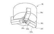
図9は、3爪チャック96を底面側から見た状態を示す斜視図である。3爪チャック96は、カソード供給ユニット47の取出しステージ80からカソード11の外周を3個の爪で把持して取り出し、組立台56に保持された電極棒9に挿入し、3個の爪の把持力を強くしてカソード11の外周を押圧して仮かしめを行う。3爪チャック96は、略円筒形状のチャック本体96aと、このチャック本体96aの下面に等角度で配置され、半径方向に移動自在とされた3個のスライド部材96bと、これらのスライド部材96bに取り付けられるチャック爪105と、チャック本体96a内に組み込まれてスライド部材96bを移動させる機構とを備えている。 FIG. 9 is a perspective view showing a state in which the 3-
チャック爪105は、スライド部材96bに取り付けられる爪本体105aと、この爪本体105aに取り付けられてカソード11把持する把持爪105bとから構成されている。把持爪105bの先端部105cは、カソード11を把持する際にカソード供給ユニット47のガイド76aとの干渉を防ぐため、下方に突出されている。図10は、把持爪105bによるカソード11の把持状態を示す底面図である。把持爪105bの先端部105cには、カソード11の外径に合せて切欠105dが設けられているため、カソード11を把持する際にカソード11の中心と3爪チャック96の中心とが多少ずれていても、カソード11は3爪チャック96の中心に位置決めされる。 The
吸着ヘッド98は、エア吸引によって電極棒9を吸着保持する機構であり、電極棒供給台39から電極棒9を吸着して取り出し、組立台56に挿入し、カソード11が組付けられた加工済み電極棒を組立台56から取り出して、電極棒集積台41に集積する。検査ヘッド99は、電極棒9に取り付けられたカソード11を軸方向で押圧して、締結力を検査する。NG用チャック100は、NG品と判断された電極棒9を組立台ユニット42から除去する。ヘッドシリンダ97は、吸着ヘッド98、検査ヘッド99、NG用チャック100を昇降させて、組立台ユニット42やカソード供給ユニット47と干渉するのを防止する。 The
キャリブレーション用照明101は、下面が点灯される照明であって、カソード認識カメラ53のカメラ座標と、スカラーロボット48のロボット座標とを対応付けるキャリブレーション時の指標として用いられる。従来のキャリブレーションでは、ロボットに設けられたキャリブレーション用の治具や、ロボットに持たせたワークの指標を照明し、これらをカメラで撮像してカメラ座標とロボット座標との対応付けを行なっていた。しかし、この方法では、大きな照明が必要であり、照明を設置するスペースも必要となるため、高コストであった。そこで、本実施形態では、ロボットヘッド88にそれ自体が指標となる照明を持たせることで、これらの問題を解決している。 The
第1電極棒認識カメラ43の両側方には、予備電極棒供給台109と、カソード排出台110とが設置されている。予備電極棒供給台109は、電極棒9を立てた状態で多数収容する台であり、組立台ユニット42でNGが発生したときに、そのNG品の電極棒に代わって新たな電極棒9を供給する。カソード排出台110は、3爪チャック96に保持されているカソード11を排出する際に使用される。 On both sides of the first electrode
制御コンピュータ34には、組立台ユニット42で電極棒9とカソード11の位置を検出する視覚センサを構成する組立部(以降K部と呼ぶ)画像処理プログラムと、カソード供給ユニット47でカソード11の位置及び姿勢を検出する視覚センサを構成するフィーダ部(以降F部と呼ぶ)画像処理プログラムとが組み込まれている。ロボットコントローラ51には、スカラーロボット48によって電極棒9を組み立てるロボットプログラムが組み込まれている。ロボットプログラムは、制御コンピュータ34によって算出された視覚センサのカメラ座標をロボット座標に変換し、このロボット座標に基づいてスカラーロボット48及びロボシリンダ58を動作させる。 The
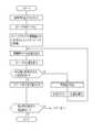
上記挿入・かしめ装置は、例えば次のように動作する。図11のフローチャートに示すように、オペレータは電極棒供給台39,予備電極棒供給台109に電極棒9がセットされていること、電極棒集積台41が空であること等を確認して操作盤35の自動運転スイッチを操作する。これにより、ロボットコントローラ51のロボットプログラムが起動する。 The insertion / caulking device operates as follows, for example. As shown in the flowchart of FIG. 11, the operator confirms that the
ロボットプログラムは、制御コンピュータ34にF部画像処理プログラムとK部画像処理プログラムとを起動させる。ここで、F部画像処理プログラムはカソード供給ユニット47を制御し、カソード認識カメラ53により取出しステージ80上に流れてきた力ソード11の姿勢と位置を認識して、力ソード11の座標をロボットコントローラ51へ返すF部タスクを実行する。また、K部画像処理プログラムは、第1電極棒認識カメラ43,第2電極棒認識カメラ44を制御し、組立台56にセットされた電極棒9及びカソード11の位置等の座標をロボットコントローラ51へ返すK部タスクを実行する。 The robot program causes the
次に、1つ目の組み立てに使用するカソード11を取得する。F部画像処理プログラムは、前回のタスクで画像サーチされた残りのカソード11があるかどうかの確認を行い、ある場合はそのまま画像取込を行い、無い場合はボールフィーダ70、行きラインフィーダ71を駆動させ、取出しステージ80上にカソード11を払い出し&供給を行う。行きラインフィーダ71は一定時間駆動後停止させ、カソード認識カメラ53により画像取込を行い取出しステージ80上に供給されたカソード11を検出する。 Next, the
カソード11が検出できない場合には、再びボールフィーダ70、行きラインフィーダ71を駆動させ、画像取込・カソード検出を繰り返す。検出された場合はカソード認識カメラ53により取得した画像を2値化し、まず取出しステージ80上にあるカソード8の個数を検出する。取出しステージ80上にあるカソード11の個数は、ボールフィーダ70内にストックしているカソード11の個数を反映しているため、その数が少ない場合には、「ボールフィーダ内のカソードの量が不足しています」等のメッセージを表示するための識別記号を出力座標に追加する。次に目標となるカソード11の周囲に他のカソードが無いかの検査(そのカソード11を取り出しに行くときに把持爪105bが他のカソードと干渉するのを防止するための検査)、また、カソード11の形状が欠けていないか等を検査し、これらの検査をクリアすればこのカソード11のカメラ座標(pixel値)をロボットコントローラ51へ送信する。 If the
これらの検査でNGとなった場合は、同画像にて検出された他のカソードについて同検査を再度実施することを繰り返す。検査にてすべてNGとなった場合には行きラインフィーダ71を駆動させて新たに取得できるカソード11を捜す。カソード11の座標出力が終わるとロボットプログラムは、受信したカメラ座標(pixel)をロボット座標(mm)に変換する等の計算をすることでカソード11の取出し位置を計算し、計算終了信号を出力する。なお、フローチャートには記載しないが、画像取込の際にはステージ照明73を取出しステージ80上に移動させ、点灯させている。座標出力後はカソード11の取り出しに邪魔にならない位置へ移動させ照明を消灯させる。 If these tests result in NG, the test is repeated for other cathodes detected in the same image. When all of the inspections are NG, the going
図12は、ロボット座標(X,Y)とカメラ座標(x,y)との関係を示している。2点鎖線で示す四角形Fは、カソード認識カメラ53による撮像範囲を示しており、取出しステージ80よりも僅かに大きな面積を有している。例えば、カメラ座標(x,y)の基準位置Osのロボット座標が(X0,Y0)であるときに、取出しステージ80上の検出位置座標(xa,ya)にあるカソード11は、ロボット座標(Xa,Ya)に位置することになる。 FIG. 12 shows the relationship between robot coordinates (X, Y) and camera coordinates (x, y). A square F indicated by a two-dot chain line indicates an imaging range of the
組立プログラムは、下記の座標変換式(1),(2)を使用して、カソード認識53によって検出されたカソード11のカメラ座標(xa,ya)から、ロボット座標(Xa,Ya)を算出する。なお、座標変換式(1),(2)のキャリブレーション係数α1,β1,α2,β2及び検出位置座標系の基準位置Osのツール位置座標(X0,Y0)は、座標変換精度に直接影響するパラメータである。
X=α1x+β1y+X0・・・式(1)
Y=α2x+β2y+Y0・・・式(2)The assembly program calculates the robot coordinates (Xa, Ya) from the camera coordinates (xa, ya) of the
X = α1x + β1y + X0 (1)
Y = α2x + β2y + Y0 Formula (2)
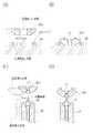
図13(A)に示すように、組立プログラムは、上記式で得られたロボット座標と、予め設定されているカソード11の基準取出位置(例えば、取出しステージ80の中央)のロボット座標とを比較し、その差分から補正量L1を算出する。そして、カソード11の基準取出位置に対応して設定されている基準取出姿勢に補正量L1を加算し、実際にカソード11を取り出すためにロボットヘッド88が移動されるロボット座標を算出し、ロボットヘッド88をその算出したロボット座標に移動させる。 As shown in FIG. 13A, the assembly program compares the robot coordinates obtained by the above equation with the robot coordinates of the reference extraction position of the
図13(B)に示すように、ロボットヘッド88は把持爪105bを開いた状態で下降され、把持爪105bを閉じてカソード11を把持する。このときの把持圧力は、カソード11を変形させない程度の圧力が用いられる。カソード11の取り出し後、ロボットヘッド88がステージ照明73の稼動範囲を抜けたところで再び次の組み立てのためのカソード検出を開始する。 As shown in FIG. 13B, the
以上のようにスカラーロボット48でカソード11を取り出している間、K部画像処理プログラムは、第1電極棒照明62,第2電極棒照明63を点灯させ、第1電極棒認識カメラ43,第2電極棒認識カメラ44で組立台56を撮像して電極棒9が残っていないことを確認する。前回のタスクの電極棒9が残っている場合には、NG用チャック100によってその電極棒9を組立台56から取り出して排出する。 As described above, while the
組立台56に電極棒9が残っていない場合、スカラーロボット48は、電極棒9を取り出すために電極棒供給台32の上方に移動し、吸着ヘッド98で電極棒96を吸い上げ、吸着した電極棒9を組立台56に挿入する。この時、吸着ヘッド98で吸着破壊を行うと同時に組立台56で吸着で吸うことで挿入を安定化させている。次にカソード11電極棒9に挿入するため、電極棒9の先端位置を検出するK部タスク1がスタートされる。 When the
K部タスク1では第1電極棒認識カメラ43及び第2電極棒認識カメラ44にてそれぞれ画像取込&サーチを行い、それぞれ電極棒9が検出されたか、また、検出された電極棒9が一定以上傾いていないかを検査したあと、問題がなければ電極棒9の先端の座標を、エラーがあればエラー内容をロボットコントローラ51へ送信する。座標/エラー出力が終わると組立プログラムは、受信したカメラ座標(pixel)をロボット座標(mm)に直す等の計算をすることでカソード11の挿入位置と挿入量を計算する。 In the K section task 1, the first electrode
第1電極棒認識カメラ43のカメラ座標(y,z)からロボット座標(Y,Z)への変換と、第2電極棒認識カメラ44のカメラ座標(x,z)からロボット座標(X,Z)への変換にも、上述した座標変換式(1)、(2)が用いられる。なお、座標変換式のキャリブレーション係数は、カメラごとに求められた固有の係数が用いられる。 Conversion from camera coordinates (y, z) of the first electrode
図13(C)に示すように、組立プログラムは、上記式で得られたロボット座標と、予め設定されている電極棒9の基準挿入位置のロボット座標とを比較し、その差分から補正量L2を算出する。そして、基準挿入位置に対応して設定されている基準挿入姿勢に補正量L2を加算し、実際に電極棒9にカソード11を挿入するためにロボットヘッド88が移動されるロボット座標を算出し、このロボット座標にロボットヘッド88を移動させる。 As shown in FIG. 13C, the assembly program compares the robot coordinates obtained by the above equation with the robot coordinates of the reference insertion position of the
図13(D)に示すように、ロボットヘッド88を下降させて電極棒9にカソード11を挿入し、一定の挿入量のところでロボットヘッド88を停止させた後、把持爪105bの把持圧力を上昇させ仮かしめを行う。仮かしめ後、把持爪105bを開き、ロボットヘッド88を退避させ、力ソード11の位置検出&本かしめを行うK部タスク2をスタートさせる。 As shown in FIG. 13 (D), the
K部タスク2では、仮かしめ後のカソード11の位置を検出し、その座標をロボットコントローラ51へ送信する。組立プログラムでは受信した座標より種々の計算を経て本かしめ位置を計算してロボシリンダ58を移動させ、本かしめを行う。本かしめの終了後、ロボシリンダ58は下降して待機位置へ戻る。 In the K section task 2, the position of the
一方、K部タスク2が行われている間に、スカラーロボット48は次の組み立てのためのカソード11の取り出しを行う。このカソード11の取り出しがスムーズに行えるように、K部タスクと並行してF部のタスクが行われている。 On the other hand, while the K section task 2 is being performed, the scalar robot 48 takes out the
力ソード11の取り出しを終えてさらにK部タスク2が終了すると、カソード11の押圧検査が行われる。スカラーロボット48は、検査ヘッド99でカソード11を下方に押圧し、バネ力にてある所定の力をかけた後検査ヘッド96が退避する。ロボットヘッド88が十分退避した後に突出量を測定するK部タスク3がスタートする。 When the extraction of the
K部タスク3では電極棒9の先端位置検出およびカソード11の上面の位置検出を行い、電極棒9の先端位置およびカソード11の上面が共に検出された場合それぞれのカメラ座標を、また、エラーが発生した場合エラー信号をロボットコントローラ51へ送信する。組立プログラムは、受信したそれぞれのカメラ座標(pixel)をロボット座標(mm)に変換し、その高さの差をとって突出量を計算する。そして、突出量が事前に定めた規定の範囲内であるかを判別し、OKであればOK品として吸着ヘッド98により組立台56から加工済み電極棒を取り出す。その後、加工済み電極棒の取り出しでミスが発生してないか検査するK部タスク4がスタートする。 In the K section task 3, the tip position of the
K部タスク4は加工済み電極棒の取り出し後、組立台56に何も残っていないかを確認するためのタスクであるので、取り込んだ画像にはミスが無ければ何も写らない。その確認方法として、取得した画像を2値化し、その2値化したものの中に色が反転した部分が存在するかどうかを検出し、その結果をロボットコントローラ51へ送信する。組立プログラムで結果を受信すると同時に、K部タスク4が終了する。 The K section task 4 is a task for confirming that nothing is left on the assembly table 56 after the processed electrode rod is taken out. Therefore, if there is no mistake in the captured image, nothing is shown. As a confirmation method, the acquired image is binarized, and it is detected whether or not the binarized portion has a color inverted portion, and the result is transmitted to the robot controller 51. At the same time that the result is received by the assembly program, the K section task 4 ends.
K部タスク4の結果より加工済み電極棒の取り出しミスが無ければ電極棒集積台41の指定位置に加工済み電極棒を集積する。その後1バッチ終了したか、あるいは停止SWが押されているかを確認し、どちらでもなければ次の電極棒9を取り出しに行き、どちらかであれば組み立てを終了し、把持しているカソード11をカソード排出台110で排出し待機位置に戻り自動組立を終了する。 If there is no mistake in taking out the processed electrode rod from the result of the K section task 4, the processed electrode rod is accumulated at the designated position of the electrode rod stacking table 41. After that, it is confirmed whether one batch has been completed or the stop SW is being pressed. If it is neither, the
上述したように、カソード11を電極棒9に精度良く取り付けるには、カメラ座標とロボット座標とが精度良く対応づけされている必要がある。そのため、挿入・かしめ装置では、定期的にカメラ座標とロボット座標とを対応させるキャリブレーションが行われる。例えば、カソード認識カメラ53のカメラ座標とロボット座標とのキャリブレーションには、本出願人により発明されたキャリブレーション方法(特願2004−268640号参照)が用いられる。以下、図14のフローチャートを参照してキャリブレーション方法について説明する。 As described above, in order to attach the
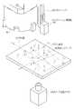
キャリブレーションは、ロボットコントローラ51に組み込まれているキャリブレーションプログラムによって制御される。図15に示すように、カソード認識カメラ53のカメラ座標とロボット座標とのキャリブレーションでは、ロボットヘッド88を取出しステージ80上に移動させ、ロボット座標上に予め設定されている4点のキャリブレーション位置C1〜C4にキャリブレーション用照明101を移動させる。そして、各キャリブレーション位置でキャリブレーション用照明101を撮像してカメラ座標を取得し、このキャリブレーション位置のカメラ座標と、予め設定されているキャリブレーション位置のロボット座標とから、前述した座標変換式(1),(2)のキャリブレーション係数を算出する。 The calibration is controlled by a calibration program incorporated in the robot controller 51. As shown in FIG. 15, in the calibration of the camera coordinates of the
なお、上記先願のキャリブレーション方法では、各キャリブレーション位置でロボットヘッドを回転させ、各回転位置の平均からキャリブレーション位置のカメラ座標を求めているが、これは、多軸ロボットによって様々な方向からワークを把持するためであり、スカラーロボット47を使用してカソード11を上方からのみ把持する本実施形態では、各キャリブレーション位置でロボットヘッド88を回転させる必要はない。 In the calibration method of the previous application, the robot head is rotated at each calibration position, and the camera coordinates of the calibration position are obtained from the average of the respective rotation positions. In this embodiment in which the
また、キャリブレーションにキャリブレーション用照明101を使用するのは、カソード供給ユニット47を小形化、低コスト化するためである。従来のキャリブレーションでは、ロボットに設けられたキャリブレーション用の治具や、ロボットに持たせたワークの指標を照明し、ロボット座標上に設定されたキャリブレーション位置に指標を移動させてカメラで撮像している。しかし、この方法では、移動された指標を確実に照明するために大きな照明が必要であり、この大きな照明を設置するスペースも必要となる。そこで、本実施形態では、ロボットヘッド88にそれ自体が指標となる照明101を持たせることで、これらの問題を解決している。 The reason why the
また、第1電極棒認識カメラ43のカメラ座標とロボット座標とのキャリブレーションと、第2電極棒認識カメラ44のカメラ座標とロボット座標とのキャリブレーションも同様の手法で、同時に行われる。まず、F部画像処理プログラムのF部タスクが実行され、ロボットヘッド88は取出しステージ80からロボット位置の指標となるカソード11を取り出す。このときのカソード11の掴み代は、カソード11を撮像しやすくするために組立時よりも短くする。 Further, the calibration of the camera coordinates of the first electrode
次に、図16に示すように、第1電極棒認識カメラ43,第2電極棒認識カメラ44の撮像範囲内に予め設定されているロボット座標上のキャリブレーション位置Cr1〜Cr8にカソード11を移動させ、各位置でカソード11のカメラ座標を取得する。このとき、キャリブレーション位置Cr1〜Cr8が頂点となる形は直方体であり、その各面はX−Y面,Y−Z面,X−Z面のいずれかと並行となる。例えば、第2電極棒認識カメラ44で撮像された画像は、キャリブレーション位置Cr1とCr2がほぼ同位置となり、同様にCr3とCr4、Cr5とCr6、Cr7とCr8もほぼ同位置となる。そこで、これらほぼ同位置の座標の平均を求め、これをキャリブレーション位置のカメラ座標とすることで、測定誤差を軽減する。 Next, as shown in FIG. 16, the
以上のように求めた各キャリブレーション位置Cr1〜Cr8のカメラ座標とロボット座標とから、座標変換式のキャリブレーション係数を求める。なお、キャリブレーション方法の詳細については、本出願人よる先願を参照されたい。 From the camera coordinates and robot coordinates of the respective calibration positions Cr1 to Cr8 obtained as described above, a calibration coefficient of a coordinate conversion formula is obtained. For details of the calibration method, refer to the prior application by the present applicant.
上述したキャリブレーションだけでは、カソード11を電極棒9に取り付けることはできず、スカラーロボット48にその動作を教えるティーチングが必要となる。このティーチングでは、ロボットに対し、対象となるワークの基準位置と、この基準位置にあるワークを取出しまたは加工する際のロボットヘッドの位置となる基準姿勢が登録される。例えば、図13(C)に示すように、電極棒9の基準挿入位置は、組立台56の上方に位置する電極棒9の先端であり、この基準挿入位置に対応する把持爪105bの基準挿入姿勢は、基準挿入位置の上方で、電極棒9の中心軸と同軸上に設定されている。 The
本発明では、基準挿入位置と基準挿入姿勢とを登録する際に、電極棒9とカソード11との中心軸を合せる作業、いわゆる調芯作業をロボットコントローラ51に組み込まれた自動調芯プログラムによって自動的に行う。調芯作業の手順を表す図17のフローチャートに示すように、まず、基準となる電極棒9が組立台56にセットされる。この電極棒9のセットは、スカラーロボット48で行ってもよい。次いで、図18に示すように、自動調芯プログラムによってロボットコントローラ51内に構成される調芯制御部110が、スカラーロボット48を制御してカソード供給ユニット47にカソード11を取りに行かせる。このときのカソード11の把持は、キャリブレーション時と同様に掴み代を短くする。 In the present invention, when registering the reference insertion position and the reference insertion posture, an operation for aligning the center axes of the
調芯制御部110は、カソード11が第1電極棒認識カメラ43及び第2電極棒認識カメラ44の撮像範囲に収まるように、ロボットヘッド88を組立台56の近傍に移動させる。そして、第1電極棒照明62,第2電極棒照明63を点灯させて電極棒9とカソード11とを照明し、第1電極棒認識カメラ43,第2電極棒認識カメラ44で撮像して、それぞれのカメラ座標を取得する。 The
電極棒9とカソード11との間の間隔L3は、自動調芯プログラムを構成する判定部113によって、予め設定されている所定の範囲内に収まるか否か判定される。間隔L3が所定の範囲を超えている場合には、自動調芯プログラムを構成する演算部115が誤差量を算出する。調芯制御部110は、誤差量分だけロボットヘッド88を移動させて再度電極棒9とカソード11とを撮像させ、判定部113で中心軸の誤差量を判定する。以上の動作を繰り返すことにより、電極棒9とカソード11との間隔が所定の範囲内に収まるので、基準位置及び基準姿勢のティーチング精度が高くなる。調芯作業の終了後、ロボットヘッド88を下降させてカソード11を電極棒9に挿入し、仮かしめを行い、一連の調芯作業が正確に行われたか確認する。また、仮かしめ後に電極棒9を撮像して、カソード11からの電極棒9の突出量を検出しカソード11の挿入位置が適切に行われているかを確認する。 It is determined whether or not the distance L3 between the
なお、上記実施形態では、キセノン管の電極棒にカソードを挿入する例について説明したが、その他の組立装置での調芯にも利用することができる。 In the above embodiment, the example in which the cathode is inserted into the electrode rod of the xenon tube has been described. However, the present invention can also be used for alignment in other assembly apparatuses.
2 挿入・かしめ装置
3 キセノン管
9 陰極側電極棒
11 カソード
34 制御コンピュータ
42 組立台ユニット
43 第1電極棒認識カメラ
44 第2電極棒認識カメラ
47 カソード供給ユニット
48 スカラーロボット
51 ロボットコントローラ
53 カソード認識カメラ
56 組立台
80 取出しステージ
101 キャリブレーション用照明
110 調芯制御部
113 判定部
115 演算部2 Insertion / Caulking Device 3
Claims (7)
Translated fromJapanese前記可動アクチュエータを制御して第2のワークを検出手段の検出範囲内に移動させ、前記検出手段を制御して第1のワークの中心軸ベクトルおよびその位置と第2のワークの中心軸ベクトルおよびその位置とを検出させる制御手段と、
検出手段の検出結果から、第1のワークの中心軸と第2のワークの中心軸との間隔が所定の範囲内にあるか否かを判定し、かつ第1のワークの中心軸ベクトルと第2のワークの中心軸ベクトルとの成す角が所定の範囲内にあるか否かを判定する判定手段と、
第1のワークの中心軸と第2のワークの中心軸との成す角およびその間隔が所定の範囲内に無いときに、その誤差量を算出する演算手段とを備え、
前記制御手段は、第1のワークの中心軸と第2のワークの中心軸との成す角およびその間隔が所定の範囲内に収まるまで、演算手段で算出された誤差量の分だけ第2のワークを移動させ、第1のワークの中心軸と第2のワークの中心軸とを検出させる動作を繰り返すことを特徴とする自動調芯装置。A holding means for holding the first workpiece, a detecting means for detecting the central axis vector of the first workpiece and its position, a second workpiece is held and moved based on the detection result of the detecting means; An automatic alignment device used in an assembling apparatus having a movable actuator for attaching a second work to a first work,
The movable actuator is controlled to move the second workpiece into the detection range of the detection means, and the detection means is controlled to control the central axis vector of the first workpiece and its position and the central axis vector of the second workpiece, and Control means for detecting the position;
From the detection result of the detecting means, it is determined whether or not the distance between the central axis of the first workpiece and the central axis of the second workpiece is within a predetermined range, and the first workpiece central axis vector and the first workpiece vector Determining means for determining whether or not an angle formed by the center axis vector of the workpiece is within a predetermined range;
A calculation means for calculating an error amount when an angle formed by the central axis of the first workpiece and the central axis of the second workpiece and the interval thereof are not within a predetermined range;
The control means sets the second amount by the amount of error calculated by the calculation means until the angle formed by the central axis of the first workpiece and the central axis of the second workpiece and the interval thereof are within a predetermined range. An automatic alignment apparatus characterized by repeating an operation of moving a workpiece and detecting a central axis of a first workpiece and a central axis of a second workpiece.
前記可動アクチュエータを制御して、第2のワークを検出手段の検出範囲内に移動させる第1のステップと、
前記検出手段を制御して、第1のワークと第2のワークとの中心軸ベクトルとその位置とを検出させる第2のステップと、
この検出結果から、第1のワークの中心軸と第2のワークの中心軸との成す角およびその間隔が所定の範囲内にあるか否かを判定する第3のステップと、
第1のワークの中心軸と第2のワークの中心軸との成す角およびその間隔が所定の範囲内に無いときに、その誤差量を算出する第4のステップと、
この誤差量の分だけ第2のワークを移動させる第5のステップを備え、
該第1のワークの中心軸と第2のワークの中心軸との間隔が所定の範囲内に収まるまで前記第2〜第5のステップを繰り返すことを特徴とする自動調芯方法。A holding means for holding the first workpiece, a detecting means for detecting the central axis vector of the first workpiece and its position, a second workpiece is held and moved based on the detection result of the detecting means; An automatic alignment method used in an assembly apparatus including a movable actuator for attaching a second workpiece to a first workpiece,
A first step of controlling the movable actuator to move the second workpiece into the detection range of the detection means;
A second step of controlling the detection means to detect a central axis vector and a position of the first workpiece and the second workpiece;
From this detection result, a third step of determining whether or not the angle formed by the central axis of the first workpiece and the central axis of the second workpiece and the interval thereof are within a predetermined range;
A fourth step of calculating an error amount when an angle formed by the central axis of the first workpiece and the central axis of the second workpiece and the interval thereof are not within a predetermined range;
A fifth step of moving the second workpiece by this amount of error,
An automatic alignment method, wherein the second to fifth steps are repeated until the distance between the center axis of the first workpiece and the center axis of the second workpiece falls within a predetermined range.
Priority Applications (1)
| Application Number | Priority Date | Filing Date | Title |
|---|---|---|---|
| JP2006003937AJP2007185723A (en) | 2006-01-11 | 2006-01-11 | Automatic alignment device and method |
Applications Claiming Priority (1)
| Application Number | Priority Date | Filing Date | Title |
|---|---|---|---|
| JP2006003937AJP2007185723A (en) | 2006-01-11 | 2006-01-11 | Automatic alignment device and method |
Publications (1)
| Publication Number | Publication Date |
|---|---|
| JP2007185723Atrue JP2007185723A (en) | 2007-07-26 |
Family
ID=38341242
Family Applications (1)
| Application Number | Title | Priority Date | Filing Date |
|---|---|---|---|
| JP2006003937APendingJP2007185723A (en) | 2006-01-11 | 2006-01-11 | Automatic alignment device and method |
Country Status (1)
| Country | Link |
|---|---|
| JP (1) | JP2007185723A (en) |
Cited By (15)
| Publication number | Priority date | Publication date | Assignee | Title |
|---|---|---|---|---|
| JP2011136416A (en)* | 2009-12-14 | 2011-07-14 | Embraer Sa | Automated positioning and alignment method and system for aircraft structures using robots |
| JP2012187663A (en)* | 2011-03-10 | 2012-10-04 | Yaskawa Electric Corp | Production apparatus |
| JP2012200805A (en)* | 2011-03-24 | 2012-10-22 | Canon Inc | Robot control device, robot control method, program, and recording medium |
| JP2013212578A (en)* | 2012-04-02 | 2013-10-17 | Boeing Co:The | Collar installation end effector |
| JP2016132049A (en)* | 2015-01-16 | 2016-07-25 | 矢崎総業株式会社 | Positioning method |
| JP2017030147A (en)* | 2016-11-01 | 2017-02-09 | キヤノン株式会社 | Assembly device, gripping hand, and assembly method for article |
| US9868181B2 (en) | 2012-02-03 | 2018-01-16 | Canon Kabushiki Kaisha | Assembly equipment and assembly method |
| JP2019119005A (en)* | 2018-01-05 | 2019-07-22 | 株式会社Fdkエンジニアリング | Calibration method of component assembly device |
| CN112976000A (en)* | 2021-02-23 | 2021-06-18 | 东莞市恒宝通光电子有限公司 | Device suitable for optical module self-adhesive electromagnetic shielding material |
| WO2021186806A1 (en)* | 2020-03-18 | 2021-09-23 | 株式会社椿本チエイン | Workpiece transfer method and workpiece transfer system |
| JP2022036832A (en)* | 2020-08-24 | 2022-03-08 | S.S.I.株式会社 | Image inspection device |
| CN114619581A (en)* | 2022-05-13 | 2022-06-14 | 河北圣昊光电科技有限公司 | Lobe of a leaf machine |
| CN115790457A (en)* | 2022-10-13 | 2023-03-14 | 中国人民解放军陆军工程大学 | Straightness measuring device and method based on laser and image processing |
| CN115890171A (en)* | 2022-11-04 | 2023-04-04 | 上海良基博方汽车发动机零部件制造股份有限公司 | Method for machining guide vane |
| CN117680977A (en)* | 2024-02-04 | 2024-03-12 | 季华实验室 | Robot feeding and splicing alignment methods, devices, equipment and media |
Citations (4)
| Publication number | Priority date | Publication date | Assignee | Title |
|---|---|---|---|---|
| JPS59160113A (en)* | 1983-03-04 | 1984-09-10 | Nippon Telegr & Teleph Corp <Ntt> | Melt sticking and connecting method of optical fiber using image pickup device |
| JPS63191589A (en)* | 1987-02-05 | 1988-08-09 | 関東自動車工業株式会社 | Method of mounting part |
| JPH06230456A (en)* | 1993-02-05 | 1994-08-19 | Fuji Photo Film Co Ltd | Caulking method |
| WO1998017444A1 (en)* | 1996-10-24 | 1998-04-30 | Fanuc Ltd | Force control robot system with visual sensor for inserting work |
- 2006
- 2006-01-11JPJP2006003937Apatent/JP2007185723A/enactivePending
Patent Citations (4)
| Publication number | Priority date | Publication date | Assignee | Title |
|---|---|---|---|---|
| JPS59160113A (en)* | 1983-03-04 | 1984-09-10 | Nippon Telegr & Teleph Corp <Ntt> | Melt sticking and connecting method of optical fiber using image pickup device |
| JPS63191589A (en)* | 1987-02-05 | 1988-08-09 | 関東自動車工業株式会社 | Method of mounting part |
| JPH06230456A (en)* | 1993-02-05 | 1994-08-19 | Fuji Photo Film Co Ltd | Caulking method |
| WO1998017444A1 (en)* | 1996-10-24 | 1998-04-30 | Fanuc Ltd | Force control robot system with visual sensor for inserting work |
Cited By (20)
| Publication number | Priority date | Publication date | Assignee | Title |
|---|---|---|---|---|
| JP2011136416A (en)* | 2009-12-14 | 2011-07-14 | Embraer Sa | Automated positioning and alignment method and system for aircraft structures using robots |
| JP2012187663A (en)* | 2011-03-10 | 2012-10-04 | Yaskawa Electric Corp | Production apparatus |
| JP2012200805A (en)* | 2011-03-24 | 2012-10-22 | Canon Inc | Robot control device, robot control method, program, and recording medium |
| US9868181B2 (en) | 2012-02-03 | 2018-01-16 | Canon Kabushiki Kaisha | Assembly equipment and assembly method |
| JP2013212578A (en)* | 2012-04-02 | 2013-10-17 | Boeing Co:The | Collar installation end effector |
| JP2016132049A (en)* | 2015-01-16 | 2016-07-25 | 矢崎総業株式会社 | Positioning method |
| CN105811219A (en)* | 2015-01-16 | 2016-07-27 | 矢崎总业株式会社 | Position aligning method |
| JP2017030147A (en)* | 2016-11-01 | 2017-02-09 | キヤノン株式会社 | Assembly device, gripping hand, and assembly method for article |
| JP2019119005A (en)* | 2018-01-05 | 2019-07-22 | 株式会社Fdkエンジニアリング | Calibration method of component assembly device |
| JP7064884B2 (en) | 2018-01-05 | 2022-05-11 | 株式会社Fdkエンジニアリング | Calibration method of parts assembly device |
| WO2021186806A1 (en)* | 2020-03-18 | 2021-09-23 | 株式会社椿本チエイン | Workpiece transfer method and workpiece transfer system |
| JP2021146430A (en)* | 2020-03-18 | 2021-09-27 | 株式会社椿本チエイン | Workpiece transfer method and workpiece transfer system |
| JP2022036832A (en)* | 2020-08-24 | 2022-03-08 | S.S.I.株式会社 | Image inspection device |
| CN112976000A (en)* | 2021-02-23 | 2021-06-18 | 东莞市恒宝通光电子有限公司 | Device suitable for optical module self-adhesive electromagnetic shielding material |
| CN112976000B (en)* | 2021-02-23 | 2022-08-09 | 东莞市恒宝通光电子有限公司 | Device suitable for optical module self-adhesive electromagnetic shielding material |
| CN114619581A (en)* | 2022-05-13 | 2022-06-14 | 河北圣昊光电科技有限公司 | Lobe of a leaf machine |
| CN115790457A (en)* | 2022-10-13 | 2023-03-14 | 中国人民解放军陆军工程大学 | Straightness measuring device and method based on laser and image processing |
| CN115890171A (en)* | 2022-11-04 | 2023-04-04 | 上海良基博方汽车发动机零部件制造股份有限公司 | Method for machining guide vane |
| CN117680977A (en)* | 2024-02-04 | 2024-03-12 | 季华实验室 | Robot feeding and splicing alignment methods, devices, equipment and media |
| CN117680977B (en)* | 2024-02-04 | 2024-04-16 | 季华实验室 | Robot feeding, splicing and aligning method, device, equipment and medium |
Similar Documents
| Publication | Publication Date | Title |
|---|---|---|
| JP2007185723A (en) | Automatic alignment device and method | |
| US10906193B2 (en) | Manufacturing system, method of constructing the manufacturing system, end effector, robot, and working method of robot | |
| US11559897B2 (en) | Reconfigurable, fixtureless manufacturing system and method assisted by learning software | |
| CN102729252B (en) | The method of operating of robot system and robot system | |
| US20130218324A1 (en) | Article assembling device using robot | |
| US20120296469A1 (en) | Sucking-conveying device having vision sensor and suction unit | |
| TW201817561A (en) | Robot system | |
| JP2006035397A (en) | Conveyance robot system | |
| JP2010105105A (en) | Automatic manufacturing apparatus | |
| WO2021039829A1 (en) | Production system | |
| JP2005286019A (en) | Substrate gripping device | |
| JPWO2008114457A1 (en) | Method for loading handler having position correction function and measuring socket of untested device | |
| WO2015083414A1 (en) | Electronic component transport apparatus | |
| JPWO2015011782A1 (en) | Inspection device | |
| JP5088187B2 (en) | Robot installation method and robot production system | |
| JPH0699382A (en) | Article setting device | |
| CN107443404A (en) | End effector, robot and robot controller | |
| JP2017113810A (en) | Assembly apparatus and method for controlling assembly apparatus | |
| JP5061965B2 (en) | Robot production system | |
| JPWO2015075775A1 (en) | Robot system | |
| JP2020138315A (en) | Production system | |
| KR101189776B1 (en) | a marking and clamping apparatus of hose and method thereof | |
| CN112938407B (en) | Gripping device and gripping method | |
| CN115697653A (en) | Image processing method, image processing apparatus, robot-mounted transport apparatus, and robot-mounted transport system | |
| JP5954969B2 (en) | Component supply apparatus and component position recognition method |
Legal Events
| Date | Code | Title | Description |
|---|---|---|---|
| A621 | Written request for application examination | Free format text:JAPANESE INTERMEDIATE CODE: A621 Effective date:20080710 | |
| A977 | Report on retrieval | Free format text:JAPANESE INTERMEDIATE CODE: A971007 Effective date:20091221 | |
| A131 | Notification of reasons for refusal | Effective date:20100106 Free format text:JAPANESE INTERMEDIATE CODE: A131 | |
| A02 | Decision of refusal | Free format text:JAPANESE INTERMEDIATE CODE: A02 Effective date:20100428 |