JP2007185360A - Merchandise display device - Google Patents
Merchandise display deviceDownload PDFInfo
- Publication number
- JP2007185360A JP2007185360AJP2006006355AJP2006006355AJP2007185360AJP 2007185360 AJP2007185360 AJP 2007185360AJP 2006006355 AJP2006006355 AJP 2006006355AJP 2006006355 AJP2006006355 AJP 2006006355AJP 2007185360 AJP2007185360 AJP 2007185360A
- Authority
- JP
- Japan
- Prior art keywords
- product
- display tool
- product display
- hanger
- wall
- Prior art date
- Legal status (The legal status is an assumption and is not a legal conclusion. Google has not performed a legal analysis and makes no representation as to the accuracy of the status listed.)
- Pending
Links
- 230000000694effectsEffects0.000description5
- 239000003566sealing materialSubstances0.000description2
- 230000004308accommodationEffects0.000description1
- 238000005452bendingMethods0.000description1
- 238000004891communicationMethods0.000description1
- 230000004060metabolic processEffects0.000description1
- 238000000034methodMethods0.000description1
- 238000004806packaging method and processMethods0.000description1
Images


Classifications
- A—HUMAN NECESSITIES
- A47—FURNITURE; DOMESTIC ARTICLES OR APPLIANCES; COFFEE MILLS; SPICE MILLS; SUCTION CLEANERS IN GENERAL
- A47F—SPECIAL FURNITURE, FITTINGS, OR ACCESSORIES FOR SHOPS, STOREHOUSES, BARS, RESTAURANTS OR THE LIKE; PAYING COUNTERS
- A47F1/00—Racks for dispensing merchandise; Containers for dispensing merchandise
- A47F1/04—Racks or containers with arrangements for dispensing articles, e.g. by means of gravity or springs
- A47F1/12—Racks or containers with arrangements for dispensing articles, e.g. by means of gravity or springs dispensing from the side of an approximately horizontal stack
Landscapes
- Display Racks (AREA)
Abstract
Description
Translated fromJapanese本発明は、商品陳列用枠桟または商品陳列用棚板上に各種商品を陳列する際に使用する商品陳列用具に関するものである。 The present invention relates to a merchandise display tool used when displaying various merchandise on a merchandise display frame bar or a merchandise display shelf.
従来の商品陳列用具として、商品陳列用枠桟に掛止するハンガー形式(掛止形式)の商品陳列用具や商品陳列棚上に載置するトレイ形式(載置形式)の商品陳列用具が存在する。そして、従来の商品陳列用具では、ハンガーまたはトレイの前方に位置する商品が取り出されると、ハンガーまたはトレイの後方に収容されている商品を順次前方に移動させて、常に商品陳列用具の手前から商品を取り出すことができるように構成されている。 As conventional product display tools, there are hanger-type (hang-type) product display tools that are hung on a product display frame and tray-type (placement-type) product display tools that are placed on a product display shelf. . In the conventional merchandise display tool, when the merchandise located in front of the hanger or tray is taken out, the merchandise stored in the rear of the hanger or tray is sequentially moved forward so that the merchandise is always in front of the merchandise display tool. It is comprised so that it can take out.
そして、ハンガー形式の商品陳列用具として、特許文献1には、先端部に継合部を設けたハンガー主杆の基部にハンガー主杆を陳列枠桟に係止する係止片を設け、継合部に着脱可能に継合し軸方向に回動不能に固定できるハンガー継杆を設け、ハンガー継杆の先端部寄りに商品を吊下げる複数個の係止溝を刻設した商品陳列用杆状ハンガー具が開示されている。 As a hanger-type product display tool,
また、トレイ形式の商品陳列用具として、特許文献2には、長方形状のベースと、ベースの一側辺に形成された凸部と、ベースの凸部と相対する側に形成されていて凸部に嵌合する凹部を有し、一つの商品陳列用具の凸部に他の商品陳列用具の凹部を嵌合させることにより複数の商品陳列用具を互いに連結させて使用できるようにした商品陳列用具が開示されている。
従来の商品陳列用具は、ハンガー形式の商品陳列用具やトレイ形式の商品陳列用具が一般的であり、商品の陳列形態に応じて、ハンガー形式の商品陳列用具またはトレイ形式の商品陳列用具を区別して使用する必要があった。 Conventional product display tools are generally hanger-type product display tools and tray-type product display tools. Depending on the product display form, hanger-type product display tools or tray-type product display tools are distinguished. Had to be used.
また、特許文献1に開示された商品陳列用杆状ハンガー具は、陳列する商品の新陳代謝を容易とするために、ハンガー主杆の継合部にハンガー継杆を着脱可能に継合しているが、ハンガーに掛止させるための孔やフックを商品に設ける必要があり、箱入りの商品を陳列するのには不向きであった。また、ハンガー形式のものは、上から見下ろすことによって商品内容を理解することができる商品(例えば、商品の上面に特徴がある商品など)を陳列するには不向きである上に、手前の商品しか見えないので、所望の商品が奥の方にあった場合は、それを発見することができなかったり、発見できても取り出すのに苦労することがあった。また、棒状のハンガーなので、過大な荷重に耐えることができない上に、上から人や物が倒れ落ちてきた場合に破損することがあった。 Moreover, the hook-shaped hanger implement for merchandise display disclosed in
さらに、特許文献2に開示された商品陳列用具は、複数のベースを連結可能に構成しているが、棚や台がない限り使用することができず、陳列設備を揃えるのに費用がかかる。 Furthermore, although the merchandise display tool disclosed in Patent Document 2 is configured to be able to connect a plurality of bases, it cannot be used unless there is a shelf or a stand, and it is expensive to arrange display equipment.
本発明は、以上のような事情に鑑みてなされたもので、棚や台がなくても枠桟があれば商品を平面的に陳列することができ、尚且つ平面上にも設置することができる商品陳列用具を提供することを目的とする。 The present invention has been made in view of the circumstances as described above, and even if there are no shelves or stands, it is possible to display products on a plane if there is a frame rail, and it can also be installed on a plane. An object is to provide a commodity display tool that can be used.
上記目的を達成するために、請求項1に記載の商品陳列用具に係る発明は、枠桟61に掛止させて使用される商品陳列用具1であって、商品を並べた状態で収容可能な開口部13と、前記枠桟61に掛止させるハンガー部16と、平面60上に載置可能な支持脚40と、を備えたことを特徴とする。
また、請求項2に記載の発明は、請求項1に記載の発明において、支持脚40は、商品陳列用具1を掛止状態に保持するストッパー部43を備えたことを特徴とする。
さらに、請求項3に記載の発明は、請求項1または2に記載の発明において、商品陳列用具1は、一側部に連結用フック21を、他側部にフック係合孔24を備え、連結用フック21をフック係合孔24に係合させることにより、複数の商品陳列用具1を相互に連結自在に構成したことを特徴とする。In order to achieve the above-mentioned object, the invention according to the commodity display tool according to
The invention according to claim 2 is characterized in that, in the invention according to
Furthermore, the invention according to claim 3 is the invention according to claim 1 or 2, wherein the
また、請求項4に記載の発明は、請求項1〜3のいずれかに記載の発明において、前記商品陳列用具1の開口部13の下方に、商品50が載置される底部26,28を設け、該底部26,28を、前記ハンガー部16から前方に向けて下降するように傾斜させて構成したことを特徴とする。
さらに、請求項5に記載の発明は、請求項1〜3のいずれかに記載の発明において、前記開口部13の上縁部11を、前記ハンガー部16から前方に向けて下降するように傾斜させたことを特徴とする。
さらに、請求項6に記載の発明は、請求項1〜5のいずれかに記載の発明において、前記ハンガー部16が設けられている側とは反対側に前壁14が形成されており、該前壁14を前方に向けて下降する傾斜面で構成したことを特徴とする。The invention according to claim 4 is the invention according to any one of
Furthermore, the invention according to claim 5 is the invention according to any one of
Furthermore, the invention according to claim 6 is the invention according to any one of
請求項1に記載の商品陳列用具に係る発明によれば、開口部に商品を収容することで、商品を並べた状態で枠桟に掛止できるので、棚や台がなくても、店舗の壁などに枠桟さえ設置されていれば、商品を平面的に展示することができる。また、商品を収容した状態の商品陳列用具を店内に搬入し、枠桟に掛止させるだけで商品の陳列が済むので、商品の搬入および設置作業が効率的にできる。さらに、支持脚によって、商品陳列用具を平面上に載置することも可能なので、枠桟に掛止しきれない場合、陳列台や棚などに置いて展示することもできる。
請求項2に記載の発明によれば、上記請求項1の効果に加えて、商品陳列用具を掛止状態に保持するストッパー部を備えるので、ハンガー形式(掛止形式)の形態で使用する際に、商品陳列用具が商品陳列用枠桟から抜け落ちないように確実に保持することが可能な商品陳列用具を提供することができる。
請求項3に記載の発明によれば、上記請求項1または2の効果に加えて、連結用フックをフック係合孔に係合させるだけで複数の商品陳列用具を相互に連結することができるので、個々の商品陳列用具が不用意に移動することがなく安定した状態で陳列を行うことができる商品陳列用具を提供することができる。商品陳列用具を連結して使用することによって、荷重に対する耐力が強くなるので、商品陳列用具の上に人や物が倒れ落ちてきても、破損しにくくなる。According to the product display device of the first aspect of the present invention, since the product is accommodated in the opening portion, the product can be hooked on the frame rail in a state where the products are arranged. As long as a frame is installed on the wall, the product can be displayed on a flat surface. Moreover, since the display of the product is completed simply by bringing the product display tool containing the product into the store and hooking it on the frame rail, it is possible to efficiently carry in and install the product. Further, since the product display tool can be placed on a flat surface by the support legs, if it cannot be completely hooked on the frame, it can be displayed on a display stand or a shelf.
According to the second aspect of the present invention, in addition to the effect of the first aspect, since the stopper portion for holding the commodity display device in the hooked state is provided, the hanger type (hanging type) is used. In addition, it is possible to provide a product display tool that can be securely held so that the product display tool does not fall out of the product display frame bar.
According to the third aspect of the present invention, in addition to the effect of the first or second aspect, a plurality of product display devices can be connected to each other simply by engaging the connecting hook with the hook engaging hole. Therefore, it is possible to provide a merchandise display tool that can be displayed in a stable state without inadvertent movement of individual merchandise display tools. By connecting and using the merchandise display tool, the load resistance is increased, so that even if a person or an object falls on the merchandise display tool, it is difficult to break.
請求項4に記載の発明によれば、上記請求項1〜3のいずれかの効果に加えて、開口部の底部に商品が載置されることとなるが、この場合において、底部がハンガー部から前方に向けて下降するように傾斜しているので、手前の商品が取り出された際に、後方から商品が順次滑り降りてくるようになる。これによって、商品を常に手前に位置させることができる商品陳列用具を提供することができる。
請求項5に記載の発明によれば、上記請求項1〜3のいずれかの効果に加えて、フランジ部がある商品は、そのフランジ部を開口部の上縁部に掛止させて収容することができるが、この場合において、開口部の上縁部が、ハンガー部から前方に向けて下降するように傾斜しているので、手前の商品が取り出された際に、後方から商品が順次滑り降りてくるようになる。これによって、常に商品を手前に位置させることができる。
請求項6に記載の発明によれば、上記請求項1〜5のいずれかの効果に加えて、ハンガー部とは反対側(即ち、手前側)に、傾斜状の前壁を設けたので、そこに商品説明などを表示することができる。これによって、消費者の見やすい位置に商品情報を表示することができるようになる。According to invention of Claim 4, in addition to the effect in any one of Claims 1-3, goods will be mounted in the bottom part of an opening part, In this case, a bottom part is a hanger part. Since the product is inclined so as to descend from the front to the front, when the front product is taken out, the product sequentially slides down from the rear. Accordingly, it is possible to provide a commodity display tool that can always position the commodity in front.
According to the fifth aspect of the invention, in addition to the effect of any one of the first to third aspects, the product having the flange portion is accommodated by hooking the flange portion to the upper edge portion of the opening portion. In this case, however, the upper edge of the opening is inclined so as to descend forward from the hanger, so that when the front product is taken out, the product sequentially slides down from the rear. Come to come. As a result, the product can always be positioned in front.
According to the invention of claim 6, in addition to the effect of any one of
本発明の実施の形態に係る商品陳列用具1を図1〜図11に基づいて説明する。
本発明の実施の形態に係る商品陳列用具1は、基本的には、図1に示すように、複数の商品陳列用具1,1を互いに連結して商品陳列用棚板(平面)60上に載置して使用する形態(トレイ形式)と、図2に示すように、複数の商品陳列用具1,1を互いに連結して商品陳列用枠桟61に掛止して使用する形態(ハンガー形式)の、2つの形態で使用できるように構成されている。A
As shown in FIG. 1, a
また、本発明の実施の形態に係る商品陳列用具1は、図1および図2に示すように、複数の商品陳列用具1,1を互いに連結して使用することができるが、単独の商品陳列用具1をトレイ形式またはハンガー形式で使用することもできる。さらに、本発明の実施の形態に係る商品陳列用具1は、商品陳列用具本体10の前壁14に商品収容部12に収容される商品50、53の商品名などを表示することができるように構成されている。 Further, as shown in FIGS. 1 and 2, the
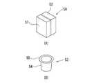
ここで、商品包装用の容器としては、図12に示すようなものを使用することができる。図12(A)に示す箱状の容器50は、分離自在の第1ケース部51と第2ケース部52とから直方体形状に構成されており、使用する場合には、第1ケース部51と第2ケース部52とを分離して、適宜の商品を収納した後、第1ケース部51と第2ケース部52とを連結する。
また、図12(B)に示すポーション容器53は、フランジ部55を有する有底円筒状の容器本体部54から構成されている。このポーション容器53を使用する場合には、フランジ部55にシール材(図示省略)を貼着して、容器本体部54に収納した商品を密封することができる。
そして、箱状の容器50およびポーション容器53の側面にも商品の具体的内容などを表示したシール材を貼り付けてもよい。Here, as a container for merchandise packaging, the one shown in FIG. 12 can be used. A box-
A
And you may affix the sealing material which displayed the specific content etc. of the product on the side surface of the box-
以下、図6〜図11に基づいて、本発明の実施の形態に係る商品陳列用具1を詳細に説明する。この商品陳列用具1は、店舗の壁などに予め設置された商品陳列用枠桟61に掛止させて使用するものであり、商品収容部12に収容された商品50,53を手前から取り出し、奥から補充していけるようになっている。
本発明の実施の形態に係る商品陳列用具1は、商品取出し側へ傾斜させた上壁11と、上壁11の前方に連設された前壁14と、上壁11の後方に連設された後壁15と、上壁11、前壁14および後壁15を連結するように、上壁11、前壁14および後壁15に連設された右側壁19および左側壁22とから形成した商品陳列用具本体10と、この商品陳列用具本体10をトレイ形式(掛止形式)またはハンガー形式(載置形式)で使用する際に用いる支持脚40と、から構成されている。また、商品陳列用具本体10の内部には、上壁11、前壁14、後壁15、右側壁19および左側壁22を相互に連結して商品陳列用具本体10を補強すると共に、後述する商品収容部12の底部(商品滑走面)を形成する縦リブ25および横リブ27が格子状に交差して一体に形成されている。Hereinafter, based on FIGS. 6-11, the
A
上壁11は、図6〜図8に示すように、商品陳列用具本体10の長手方向に細長い平板状に形成されると共に、前方すなわち商品取り出し方向へ緩やかに湾曲するように傾斜して形成されている。この場合の傾斜角度αは10°〜35°、好ましくは、15°である。また、上壁11には、商品陳列用具本体10の長手方向に沿って商品収容部12を構成する長円形状の開口部13が形成されている。上壁11の上面が開口部13の上縁部を形成している。そして、開口部13の下方には、商品収容部12の底部を形成する縦リブ25と横リブ27が存在するだけで、開口部13の下方は、格子状に交差する縦リブ25および横リブ27を介して下方に開放されている。なお、商品収容部12の底部の傾斜角度も、上壁11の傾斜角度に合わせて、10°〜35°、好ましくは、15°に設定されている。 As shown in FIGS. 6 to 8, the
そして、上壁11の前端に前壁14が連設して一体に形成されている。前壁14は、上壁11の傾斜角度よりも大きな傾斜角度β(65°〜75°、好ましくは、70°)で商品取り出し方向へ下降する傾斜面となっており、前壁14の表面に商品の具体的内容などを表示したシール(図示省略)などを貼着できるように構成されている。 A
また、上壁11の後端に後壁15がほぼ直角に連設して一体に形成されている。この後壁15の内側の両側部は、後述する右側壁19および左側壁22の後端に一体に連設されると共に、後述する縦リブ25の後端にも一体に連設されている。 A
右側壁19は、図6および図9に示すように、前壁14、上壁11および後壁15の右側端縁部から一定距離、すなわち、後述する一対の右側壁突出部20,20の突出距離だけ内側に位置して前壁14、上壁11および後壁15に連設して一体に形成され、商品陳列用具本体10の一側部を構成している。また、右側壁19には、一対の中空状の右側壁突出部20,20が右側壁19の側面から外方に突出するように一体に形成されている。これらの一対の右側壁突出部20,20は、図9および図10に示すように、上壁11の右側端縁部の延長線上から突出しないように形成されている。そして、各右側壁突出部20,20の下方には、各右側壁突出部20,20の側面から外方に突出するように連結用フック21,21が一体に形成されている。各連結用フック21,21は、図10(B)に示すように、下方にほぼL字形状に屈曲して形成されている。 As shown in FIGS. 6 and 9, the
また、右側壁19のハンガー部16の近傍には、後述する支持脚40を枢支する支持脚枢支孔31が形成されており、この支持脚枢支孔31の両側に、支持脚起立保持部29とストッパー保持部30が、右側壁19の側面から外方に突出するように形成されている。 Further, a support leg
左側壁22は、図7および図9に示すように、前壁14、上壁11および後壁15の左側端縁部から一定距離、すなわち、後述する一対の左側壁突出部23,23の突出距離だけ内側に位置して前壁14、上壁11および後壁15に連設して一体に形成され、商品陳列用具本体10の他側部を構成している。また、左側壁22には、一対の中空状の左側壁突出部23,23が左側壁22の側面から外方に突出するように一体に形成されている。一対の左側壁突出部23,23は、図9および図10(B)に示すように、上壁11の左側端縁部の延長線上から突出しないように形成されている。そして、各左側壁突出部23,23の下方には、各右側壁突出部20,20の側面に形成した連結用フック21,21に対応させて、フック係合孔24,24が形成されている。各フック係合孔24,24は、中空状の各左側壁突出部23,23内に連通して形成されている。 7 and 9, the
また、左側壁22のハンガー部16の近傍には、右側壁19の支持脚枢支孔31に対応させて、支持脚40を枢支する支持脚枢支孔31が形成されており、この支持脚枢支孔31の両側には、右側壁19の支持脚起立保持部29およびストッパー保持部30に対応させて、支持脚起立保持部29とストッパー保持部30が、左側壁22の側面から外方に突出するように形成されている。 A support leg
また、図9に示すように、右側壁19と左側壁22との間には、縦リブ25が配設されており、この縦リブ25は、商品収容部12に対応する部位を除いて、右側壁19および左側壁22とほぼ同じ形状(図6および図7参照)で、前壁14、上壁11および後壁15に一体に連設されて形成されている。図6、図7および図10に示すように、縦リブ25の縦リブ上端縁26は、商品収容部12の形状に合わせて切り欠かれており、商品収容部12の底部の一部を形成している。 Further, as shown in FIG. 9, a
さらに、図6〜図10に示すように、右側壁19、縦リブ25および左側壁22は、3つの横リブ27で一体に連設されている。各横リブ27の横リブ上端縁28は、縦リブ上端縁26の高さと一致するように形成されており、縦リブ上端縁26と共同して、商品収容部12の底部(商品の滑走面)の一部を形成している。 Further, as shown in FIGS. 6 to 10, the
また、図6、図7および図9に示すように、商品陳列用具本体10の後壁15の近傍にハンガー部16が形成されている。このハンガー部16は、右側壁19、縦リブ25および左側壁22を、商品陳列用枠桟61(図2および図4参照)の形状に合わせて切り欠いて形成されている。ハンガー部16の前後に一対のハンガー部横リブ18,18が形成されており、各ハンガー部横リブ18,18は、右側壁19、縦リブ25および左側壁22に連設して形成されると共に、上壁11および後壁15にも連設して形成されている。また、右側壁19と縦リブ25との間および左側壁22と縦リブ25との間には、それぞれハンガー部縦リブ17が、ハンガー部16の形状に合わせて形成されている。 As shown in FIGS. 6, 7, and 9, a
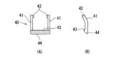
図11に示すように、支持脚40は、接地部44の両端に一対のアーム部41を一体に連設してほぼコ字形状に形成されている。接地部44の近傍でアーム部41側にストッパー部43が併設して形成されている。各アーム部41の先端側の内側には、一対の枢支軸42,42が対向するように形成されており、各枢支軸42,42は、各支持脚枢支孔31,31(図6および図7参照)に挿入して取り付けられる。そして、商品陳列用具1をトレイ形式で使用する際(図1および図3参照)には、支持脚40は、各アーム部41,41を各支持脚起立保持部29,29に当接させた状態で保持され、接地部44を介して商品陳列用具本体10を商品陳列用棚板60の上面に載置させる。また、商品陳列用具1をハンガー形式で使用する際(図2および図4参照)には、ハンガー部16を商品陳列用枠桟61に掛止した後、支持脚40を回動させて、各アーム部41,41を各ストッパー保持部30,30に当接させた状態で保持して、ハンガー部16の開口部をストッパー部42で閉鎖する。 As shown in FIG. 11, the
次に、本発明の実施の形態に係る商品陳列用具1の使用形態を図1〜図5に基づいて説明する。
本発明の実施の形態に係る商品陳列用具1は、図1および図2に示すように、複数の商品陳列用具1、1を連結して使用することができ、また、一個の商品陳列用具1を単独で使用することもできるが、いずれの場合でも基本的な使用形態は同様であるため、複数の商品陳列用具1、1を連結して使用する形態について説明する。Next, a usage pattern of the
As shown in FIG. 1 and FIG. 2, the
まず、複数の商品陳列用具1、1を連結する際には、図5(A)に矢印で示すように、一方の商品陳列用具本体10の一側部(右側壁突出部20)の連結用フック21を、他方の商品陳列用具本体10の他側部(左側壁突出部23)のフック係合孔24に挿入する。すると、図5(B)に示すように、一方の商品陳列用具本体10の連結用フック21が他方の商品陳列用具本体10のフック係合孔24に挿入された状態で係合され、一方の商品陳列用具本体10と他方の商品陳列用具本体10は相互に連結された状態となる。そして、さらに複数の商品陳列用具1、1を追加して連結する場合には、以上の動作を繰り返すことにより、適宜数量の商品陳列用具1、1を連結した状態とすることができる。 First, when connecting a plurality of
その後、商品陳列形態に合わせて、すなわち、図1に示すトレイ形式(載置形式)では、支持脚40を起立させて、支持脚40の接地部44を商品陳列用棚板60の上面に接地させて、適宜数量の商品陳列用具1、1を連結した状態で商品陳列用棚板60の上面に載置する。そして、例えば、商品50を商品収容部12に収容することにより、トレイ形式の商品陳列用具として使用することができる。 Thereafter, in accordance with the product display form, that is, in the tray form (placement form) shown in FIG. Then, an appropriate quantity of the
また、図2に示すハンガー形式(掛止形式)では、ハンガー部16を商品陳列用枠桟61に掛止した後、商品陳列用枠桟61を挟持するように支持脚40を回動させて、適宜数量の商品陳列用具1、1を連結した状態で商品陳列用枠桟61に掛止する。そして、例えば、商品53を商品収容部12に収容することにより、ハンガー形式の商品陳列用具として使用することができる。 Further, in the hanger type (hanging type) shown in FIG. Then, an appropriate quantity of the
トレイ形式またはハンガー形式のいずれの形態で使用する場合でも、箱状の容器50の場合は、図3に示すように、商品陳列用具本体10の上壁11に形成した商品収容部12は、前方(商品取出し方向)に傾斜した状態で設置されるため、商品収容部12に収容した前方の商品50を取り出すと、次の商品50は、商品収容部12の底部、すなわち、縦リブ上端縁26と横リブ上端縁28の上面を滑走して順次前方に移動される。また、ポーション容器53の場合は、図4に示すように、フランジ部55が上壁11、すなわち、開口部13の上縁部に接しているため、商品収容部12に収容した前方の商品53を取り出すと、次の商品53は、商品収容部12の上壁11、すなわち、開口部13の上縁部を滑走して順次前方に移動される。そのため、商品収容部12内に収容される商品50,53は、常に商品陳列用具1の前方にあるため、商品を有無を確認することが容易となる。 In the case of a box-
なお、商品陳列用具に収容された商品が、図12(A)に示すような箱状の容器50に収納されている場合、上壁11に設けられた開口部13の底部(即ち、縦リブ上縁部26、横リブ上縁部28)に接しながら次の商品が滑り降りてくるので、これらの縦リブ上縁部26および横リブ上縁部28の上面に摩擦係数が低くなるような表面処理を施すのが好ましい。
一方、図12(B)に示すようなポーション容器53に収納されている場合、容器53のフランジ部55と上壁11とが接するので、上壁11に摩擦係数が低くなるような表面処理を施すのが好ましい。また、本発明において開口部13の寸法は、商品50,53を整列した状態で陳列できるように、陳列される商品50,53の横幅に合わせて設計するのが好ましいが、広範な商品に使用できるようにしてもよい。
また、本実施の形態における側壁部(右側壁19および左側壁22)の下端部を前壁14の下端部の位置まで延長し、その延長部をもって支持脚を構成してもよいし、支持脚40にストッパー部43を設けなくてもよい。また、連結用フック21を設けず単品(商品陳列用具単体)で使用できるようにしてもよいし、前壁14を傾斜状にしなくてもよいし、前壁自体を設けなくてもよい。When the product stored in the product display tool is stored in a box-shaped
On the other hand, when the container is stored in a
Further, the lower end portions of the side wall portions (the
1 商品陳列用具
10 商品陳列用具本体
11 上壁(開口部の上縁部)
12 商品収容部
13 開口部
14 前壁
15 後壁
16 ハンガー部
17 ハンガー部縦リブ
18 ハンガー部横リブ
19 右側壁
20 右側壁突出部
21 連結用フック
22 左側壁
23 左側壁突出部
24 フック係合孔
25 縦リブ
26 縦リブ上端縁
27 横リブ
28 横リブ上端縁
29 支持脚起立保持部
30 ストッパー保持部
31 支持脚枢支孔
40 支持脚
41 アーム部
42 枢支軸
43 ストッパー部
44 接地部
50 箱状の容器(商品)
51 第1ケース部
52 第2ケース部
53 ポーション容器(商品)
54 容器本体部
55 容器フランジ部
60 商品陳列用棚板(平面)
61 商品陳列用枠桟(枠桟)
1
12
51
54
61 Product display frame (frame frame)
Claims (6)
Translated fromJapaneseThe front wall is formed on the side opposite to the side on which the hanger part is provided, and the front wall is configured by an inclined surface that descends toward the front. The product display tool according to claim 1.
Priority Applications (4)
| Application Number | Priority Date | Filing Date | Title |
|---|---|---|---|
| JP2006006355AJP2007185360A (en) | 2006-01-13 | 2006-01-13 | Merchandise display device |
| SG200700259-5ASG134257A1 (en) | 2006-01-13 | 2007-01-12 | Merchandise display implement |
| US11/653,120US20070175843A1 (en) | 2006-01-13 | 2007-01-12 | Merchandise display implement |
| EP07100508AEP1808102A1 (en) | 2006-01-13 | 2007-01-15 | Merchandise display implement |
Applications Claiming Priority (1)
| Application Number | Priority Date | Filing Date | Title |
|---|---|---|---|
| JP2006006355AJP2007185360A (en) | 2006-01-13 | 2006-01-13 | Merchandise display device |
Publications (1)
| Publication Number | Publication Date |
|---|---|
| JP2007185360Atrue JP2007185360A (en) | 2007-07-26 |
Family
ID=37907823
Family Applications (1)
| Application Number | Title | Priority Date | Filing Date |
|---|---|---|---|
| JP2006006355APendingJP2007185360A (en) | 2006-01-13 | 2006-01-13 | Merchandise display device |
Country Status (4)
| Country | Link |
|---|---|
| US (1) | US20070175843A1 (en) |
| EP (1) | EP1808102A1 (en) |
| JP (1) | JP2007185360A (en) |
| SG (1) | SG134257A1 (en) |
Cited By (3)
| Publication number | Priority date | Publication date | Assignee | Title |
|---|---|---|---|---|
| JP2012232016A (en)* | 2011-05-06 | 2012-11-29 | Japan Tobacco Inc | Product display shelf |
| US9514436B2 (en) | 2006-09-05 | 2016-12-06 | The Nielsen Company (Us), Llc | Method and system for predicting audience viewing behavior |
| JP2019017481A (en)* | 2017-07-12 | 2019-02-07 | 三協立山株式会社 | Merchandise display tool |
Families Citing this family (8)
| Publication number | Priority date | Publication date | Assignee | Title |
|---|---|---|---|---|
| EP2063747B1 (en)* | 2006-09-06 | 2013-05-22 | 3M Innovative Properties Company | Horizontally mounted shelf assembly and accessories therefor |
| US9569986B2 (en) | 2012-02-27 | 2017-02-14 | The Nielsen Company (Us), Llc | System and method for gathering and analyzing biometric user feedback for use in social media and advertising applications |
| US8789712B2 (en)* | 2012-06-28 | 2014-07-29 | Target Brands, Inc. | Loose item display fixture |
| US9206827B2 (en) | 2012-11-20 | 2015-12-08 | Avery Dennison Corporation | Wall mount organization system |
| CN103883868B (en)* | 2012-12-20 | 2016-12-14 | 重庆凌云工具有限公司 | Cargo path fixing device |
| US9936250B2 (en) | 2015-05-19 | 2018-04-03 | The Nielsen Company (Us), Llc | Methods and apparatus to adjust content presented to an individual |
| US10219639B2 (en)* | 2015-07-07 | 2019-03-05 | Display Technologies, Llc | Product display unit having an adjustable width |
| US10500713B2 (en)* | 2017-09-14 | 2019-12-10 | Black & Decker Inc. | Wall hanging system |
Citations (4)
| Publication number | Priority date | Publication date | Assignee | Title |
|---|---|---|---|---|
| JPS5869605A (en)* | 1981-09-21 | 1983-04-25 | ザ・ミ−ド・コ−ポレ−シヨン | Base plate for product |
| US5240126A (en)* | 1992-05-29 | 1993-08-31 | The Gillette Company | Dispensing rack apparatus |
| JPH11346880A (en)* | 1998-06-05 | 1999-12-21 | Kawajun Kk | Commodity display device |
| JP2000139642A (en)* | 1998-11-09 | 2000-05-23 | Kanebo Ltd | Display shelf |
Family Cites Families (15)
| Publication number | Priority date | Publication date | Assignee | Title |
|---|---|---|---|---|
| US4454949A (en)* | 1982-04-16 | 1984-06-19 | Paul Flum Ideas, Inc. | Product merchandising display unit |
| US5024336A (en)* | 1990-07-24 | 1991-06-18 | The Mead Corporation | Composite organizer |
| US5634564A (en)* | 1995-06-13 | 1997-06-03 | The Mead Corporation | Pusher device for dispensing articles |
| US5645176A (en)* | 1996-08-08 | 1997-07-08 | Display Technologies, Inc. | Display rack with channel front member |
| JPH1146942A (en)* | 1997-07-31 | 1999-02-23 | Nanba Seisakusho:Kk | Rod hanger for article display |
| US6325221B2 (en)* | 1997-11-08 | 2001-12-04 | Display Industries, Llc | Merchandising display track device of multiple-piece construction |
| US6328170B1 (en)* | 1999-10-20 | 2001-12-11 | Daewoo Electronics Co., Ltd. | Gravity feed shelf |
| FR2821255B1 (en)* | 2001-02-28 | 2003-09-19 | Hermes Metal | DEVICE FOR PRESENTING GOODS OF THE PIN TYPE |
| US6523702B1 (en)* | 2001-10-31 | 2003-02-25 | Display Industries, Llc | Inclined merchandising display track device |
| US6722509B1 (en)* | 2002-10-31 | 2004-04-20 | Display Industries, Llc. | Display track device with front panels and top stop members |
| US6715621B2 (en)* | 2002-08-01 | 2004-04-06 | Paul Flum Ideas, Inc. | Product merchandising display unit with pull through front wall members |
| US6695153B1 (en)* | 2002-08-28 | 2004-02-24 | Hui-Chen Chao | Rack for holding a pistol-type lawn sprinkler nozzle |
| US7104410B2 (en)* | 2002-10-31 | 2006-09-12 | Display Industries, Llc. | Display track device with anti-torsion bar |
| US6880709B2 (en)* | 2002-12-23 | 2005-04-19 | Shin Tai Spurt Water Of The Garden Tools, Co., Ltd. | Foot structure of a rack for holding spray nozzles |
| US6877618B2 (en)* | 2003-01-22 | 2005-04-12 | New Dimensions Research Corporation | Shelf and display device |
- 2006
- 2006-01-13JPJP2006006355Apatent/JP2007185360A/enactivePending
- 2007
- 2007-01-12SGSG200700259-5Apatent/SG134257A1/enunknown
- 2007-01-12USUS11/653,120patent/US20070175843A1/ennot_activeAbandoned
- 2007-01-15EPEP07100508Apatent/EP1808102A1/ennot_activeWithdrawn
Patent Citations (4)
| Publication number | Priority date | Publication date | Assignee | Title |
|---|---|---|---|---|
| JPS5869605A (en)* | 1981-09-21 | 1983-04-25 | ザ・ミ−ド・コ−ポレ−シヨン | Base plate for product |
| US5240126A (en)* | 1992-05-29 | 1993-08-31 | The Gillette Company | Dispensing rack apparatus |
| JPH11346880A (en)* | 1998-06-05 | 1999-12-21 | Kawajun Kk | Commodity display device |
| JP2000139642A (en)* | 1998-11-09 | 2000-05-23 | Kanebo Ltd | Display shelf |
Cited By (3)
| Publication number | Priority date | Publication date | Assignee | Title |
|---|---|---|---|---|
| US9514436B2 (en) | 2006-09-05 | 2016-12-06 | The Nielsen Company (Us), Llc | Method and system for predicting audience viewing behavior |
| JP2012232016A (en)* | 2011-05-06 | 2012-11-29 | Japan Tobacco Inc | Product display shelf |
| JP2019017481A (en)* | 2017-07-12 | 2019-02-07 | 三協立山株式会社 | Merchandise display tool |
Also Published As
| Publication number | Publication date |
|---|---|
| SG134257A1 (en) | 2007-08-29 |
| EP1808102A1 (en) | 2007-07-18 |
| US20070175843A1 (en) | 2007-08-02 |
Similar Documents
| Publication | Publication Date | Title |
|---|---|---|
| JP2007185360A (en) | Merchandise display device | |
| US7520394B2 (en) | Angulated package and display system | |
| US6109447A (en) | System for shipping and displaying small articles | |
| JP6125010B2 (en) | Suspension device | |
| JP4693011B2 (en) | Product display | |
| JP3207340U (en) | Display case | |
| JP3166853U (en) | Display tools | |
| JP3156106U (en) | Display tools | |
| JP3219729U (en) | Product display container | |
| JP3164199U (en) | Case | |
| JP3160038U (en) | Hook for accessories | |
| JP2020078460A (en) | Display device | |
| JP3115173U (en) | Product display tools | |
| JP2008100734A (en) | Packaging box for display | |
| JPS6223721Y2 (en) | ||
| JP3192871U (en) | Product display | |
| KR200382334Y1 (en) | Plastic Packaging Containers for Sale | |
| JPH0320263Y2 (en) | ||
| CN100434021C (en) | Upper unit and display utensils | |
| JP3214295U (en) | Product display storage box | |
| JP3157823U (en) | Hanger board for product display | |
| JP3147809U (en) | Paper catalog stand | |
| JP3187285U (en) | Display device | |
| CN201070167Y (en) | Horticulture tool hanging plate | |
| JP4414179B2 (en) | Display stand device |
Legal Events
| Date | Code | Title | Description |
|---|---|---|---|
| A621 | Written request for application examination | Free format text:JAPANESE INTERMEDIATE CODE: A621 Effective date:20081105 | |
| A977 | Report on retrieval | Free format text:JAPANESE INTERMEDIATE CODE: A971007 Effective date:20110728 | |
| A131 | Notification of reasons for refusal | Free format text:JAPANESE INTERMEDIATE CODE: A131 Effective date:20110921 | |
| A02 | Decision of refusal | Free format text:JAPANESE INTERMEDIATE CODE: A02 Effective date:20120208 |