JP2007184276A - Plug-in connector - Google Patents
Plug-in connectorDownload PDFInfo
- Publication number
- JP2007184276A JP2007184276AJP2006354732AJP2006354732AJP2007184276AJP 2007184276 AJP2007184276 AJP 2007184276AJP 2006354732 AJP2006354732 AJP 2006354732AJP 2006354732 AJP2006354732 AJP 2006354732AJP 2007184276 AJP2007184276 AJP 2007184276A
- Authority
- JP
- Japan
- Prior art keywords
- plug
- connector
- contact
- section
- printed circuit
- Prior art date
- Legal status (The legal status is an assumption and is not a legal conclusion. Google has not performed a legal analysis and makes no representation as to the accuracy of the status listed.)
- Granted
Links
Images


Classifications
- H—ELECTRICITY
- H01—ELECTRIC ELEMENTS
- H01R—ELECTRICALLY-CONDUCTIVE CONNECTIONS; STRUCTURAL ASSOCIATIONS OF A PLURALITY OF MUTUALLY-INSULATED ELECTRICAL CONNECTING ELEMENTS; COUPLING DEVICES; CURRENT COLLECTORS
- H01R13/00—Details of coupling devices of the kinds covered by groups H01R12/70 or H01R24/00 - H01R33/00
- H01R13/648—Protective earth or shield arrangements on coupling devices, e.g. anti-static shielding
- H01R13/658—High frequency shielding arrangements, e.g. against EMI [Electro-Magnetic Interference] or EMP [Electro-Magnetic Pulse]
- H01R13/6581—Shield structure
- H01R13/6585—Shielding material individually surrounding or interposed between mutually spaced contacts
- H01R13/6586—Shielding material individually surrounding or interposed between mutually spaced contacts for separating multiple connector modules
- H01R13/6587—Shielding material individually surrounding or interposed between mutually spaced contacts for separating multiple connector modules for mounting on PCBs
- H—ELECTRICITY
- H01—ELECTRIC ELEMENTS
- H01R—ELECTRICALLY-CONDUCTIVE CONNECTIONS; STRUCTURAL ASSOCIATIONS OF A PLURALITY OF MUTUALLY-INSULATED ELECTRICAL CONNECTING ELEMENTS; COUPLING DEVICES; CURRENT COLLECTORS
- H01R12/00—Structural associations of a plurality of mutually-insulated electrical connecting elements, specially adapted for printed circuits, e.g. printed circuit boards [PCB], flat or ribbon cables, or like generally planar structures, e.g. terminal strips, terminal blocks; Coupling devices specially adapted for printed circuits, flat or ribbon cables, or like generally planar structures; Terminals specially adapted for contact with, or insertion into, printed circuits, flat or ribbon cables, or like generally planar structures
- H01R12/70—Coupling devices
- H01R12/71—Coupling devices for rigid printing circuits or like structures
- H01R12/72—Coupling devices for rigid printing circuits or like structures coupling with the edge of the rigid printed circuits or like structures
- H01R12/722—Coupling devices for rigid printing circuits or like structures coupling with the edge of the rigid printed circuits or like structures coupling devices mounted on the edge of the printed circuits
- H01R12/724—Coupling devices for rigid printing circuits or like structures coupling with the edge of the rigid printed circuits or like structures coupling devices mounted on the edge of the printed circuits containing contact members forming a right angle
- H—ELECTRICITY
- H01—ELECTRIC ELEMENTS
- H01R—ELECTRICALLY-CONDUCTIVE CONNECTIONS; STRUCTURAL ASSOCIATIONS OF A PLURALITY OF MUTUALLY-INSULATED ELECTRICAL CONNECTING ELEMENTS; COUPLING DEVICES; CURRENT COLLECTORS
- H01R13/00—Details of coupling devices of the kinds covered by groups H01R12/70 or H01R24/00 - H01R33/00
- H01R13/46—Bases; Cases
- H01R13/514—Bases; Cases composed as a modular blocks or assembly, i.e. composed of co-operating parts provided with contact members or holding contact members between them
Landscapes
- Details Of Connecting Devices For Male And Female Coupling (AREA)
- Coupling Device And Connection With Printed Circuit (AREA)
Abstract
Translated fromJapaneseDescription
Translated fromJapanese本発明は、電気的又は電子的なシステム内に嵌め込み可能な、プリント基板、回路カード(Schaltungskarte)又は電気素子上に配置するための、遮蔽部材を備えた4極多列型の差し込み接続コネクタであって、ケーシングが設けられていて、該ケーシングの外側及び内側に、差し込み接続コネクタの構成部分が位置決め及び固定されており、信号を伝送するための電気的な接点部分が設けられていて、これらの接点部分は、一端部で接続区分を有していて、他端部で導電性の固定区分を有しており、電気的な遮蔽部材が設けられていて、これらの遮蔽部材が、少なくとも1つの導電性の接点区分を有しており、組み立て側で前記ケーシングから突き出す、電気的な接点部分の固定区分と、前記電気的な遮蔽部材の接点区分とが、所定の格子状に配置されていて、はんだ付けによって前記プリント基板と接続可能である形式のものに関する。遮蔽部材を備えた4極多列型の差し込み接続コネクタにおいては、該差し込み接続コネクタによって、電気的な導線、特に構造群の電子構成部分、特にプリント基板、ボード(Steckkarte)及びこれと類似のシステム構成素子を互いに、有利には解除可能に接続され得るようになっている。このような差し込み接続コネクタは、差し込み接続部のいわゆるナイフストリップ(Messerleisten)又はばねストリップ(Federleisten)である。 The present invention is a four-pole multi-row plug-in connector with a shielding member for placement on a printed circuit board, circuit card (Schaltungskarte) or electrical element that can be fitted into an electrical or electronic system. A casing is provided, and the components of the plug-in connector are positioned and fixed on the outside and inside of the casing, and electrical contact parts for transmitting signals are provided. The contact portion has a connection section at one end and a conductive fixed section at the other end, and is provided with an electrical shielding member, and these shielding members are at least one. There are two conductive contact sections, and the fixed section of the electrical contact portion protruding from the casing on the assembly side and the contact section of the electrical shielding member are arranged in a predetermined grid pattern. It has been concerns of the type which is connectable to the printed circuit board by soldering. In a four-pole multi-row plug-in connector with a shielding member, the plug-in connector allows an electrical lead, in particular an electronic component of a structural group, in particular a printed circuit board, a board (Steckkarte) and similar systems The components can be connected to each other, preferably releasably. Such plug-in connectors are so-called knife strips or spring strips (Federleisten) of plug-in connections.
このような差し込み接続コネクタには、ユーザーによって常に、電気的及び機械的なパラメータに関連して、特に高い伝送率、機械的な強度にも関連して、また特に良好な剛性及び引張負荷に関連して高い要求が課せられる。それと同時に、接点間隔の最小化及び差し込み接続部の大きさに関する永久的な要求がある。それと同時に、製作コストを安価に、少なくとも(比較的)安価に維持する必要がある。 Such plug-in connectors are always associated by the user with regard to electrical and mechanical parameters, especially with regard to high transmission rates, mechanical strength, and particularly with respect to good stiffness and tensile loads. High demands. At the same time, there are permanent requirements regarding the minimization of the contact spacing and the size of the plug connection. At the same time, the production costs need to be kept low, at least (relatively) low.
遮蔽部材を備えた差し込み接続コネクタを、単極の又は多極の差し込み接続部のために、プラグ部分又はソケット部分、つまりナイフストリップ又はばねストリップが、そのケーシング部分の外側又は内側に配置された大面積のシールドプレートを備えた構成のものが公知である。このような構造形式、例えばヨーロッパ公開特許第0422785号明細書による差し込み接続コネクタは、プラグ部分に外部から作用する妨害信号を遮蔽するのに効果的である。このような差し込み接続コネクタにおいては、プリント基板における機械的な固定がねじによって行われ、この場合それと同時に外側の遮蔽部材が固定される、という欠点がある。 For plug-in connectors with shielding members, for single-pole or multi-pole plug-in connections, plug or socket parts, i.e. knife strips or spring strips, are arranged on the outside or inside of the casing part. The thing of the structure provided with the shield plate of an area is well-known. Such a structural type, for example, a plug-in connector according to EP 0422785, is effective in shielding interfering signals acting on the plug part from the outside. Such a plug-in connector has a disadvantage that mechanical fixation on the printed circuit board is performed by screws, and in this case, the outer shielding member is fixed at the same time.
特に多極式でしかも多列型の、冒頭に述べた形式の差し込み接続コネクタに使用するために配置された、導電性の個別の接点部材又はこのような接点部材のグループを遮蔽するために、前記形式の遮蔽部材は、特に高いデータ率若しくは高周波数の信号が伝送される場合に非効果的である。
そこで本発明の課題は、電気的又は電子的なシステム内に嵌め込み可能な、プリント基板、回路カード等の電気素子上に配置するための、遮蔽部材を備えた4極多列型の差し込み接続コネクタを改良して、製作コストを最適化(つまり小型の又は軽量の差し込み接続コネクタ若しくはより少ない使用材料)すると同時に、機械的に非常に良好な電流容量及び非常に良好な電気的パラメータ、つまり高い伝送速度、及び信号接点間の飛び移りに対する非常に良好な遮蔽が得られるようなものを提供することである。 SUMMARY OF THE INVENTION Accordingly, an object of the present invention is to provide a four-pole multi-row plug-in connector having a shielding member for placement on an electric element such as a printed circuit board or a circuit card that can be fitted in an electric or electronic system. To optimize manufacturing costs (ie small or light plug-in connectors or less material to use), while at the same time mechanically very good current capacity and very good electrical parameters, ie high transmission It is to provide a very good shielding against speed and jumping between signal contacts.
この課題を解決した請求項1に記載した特徴を有する本発明によれば、電気的な接点部分の導電性の固定区分の自由端部がSMD接点であって、前記遮蔽部材の少なくとも1つの導電性の接点区分が同時に固定ピンであって、該固定ピンが、プリント基板上に差し込み接続コネクタを配置した時に、THR技術によるはんだ接続を実施するために、このプリント基板の貫通孔内に突入するようになっている。従属請求項2〜16には、本発明の有利な実施態様若しくは変化実施例が記載されている。 According to the present invention having the characteristics described in claim 1, which solves this problem, the free end of the conductive fixed section of the electrical contact portion is an SMD contact, and the at least one conductive member of the shielding member is provided. The contact point of the directional contact is a fixed pin at the same time, and the fixed pin rushes into the through hole of the printed circuit board to perform solder connection by THR technology when the plug connector is arranged on the printed circuit board. It is like that. The dependent claims 2 to 16 describe advantageous embodiments or variants of the invention.
遮蔽部材を備えた新規な多極式多列型の差し込み接続コネクタ(以下では短縮して差し込み接続部材とする)によって、THR技術を自動化されたSMD製作プロセス内に定性的に高価値で統合し、かつこのような形式の差し込み接続コネクタを製作すると同時に、安価な製作コストを得るための前提が得られる。つまり、このような形式の新規な差し込み接続コネクタによって、THR技術(Through-Hole-Reflow;スルーホールリフロー)をSMT技術(Surface Mount Technology;表面実装技術)と共に、冒頭で述べた形式の差し込み接続コネクタに(ばねストリップ及びナイフストリップ)おいても使用することができる、ということである。即ち、10GBit/sのデータ率を補助するSMD接続部のHF技術的な利点を、許容され得る引き出し力が比較可能な構成素子の押し込み技術の約4〜8倍大きく、しかも高い機械的な形状安定性を提供するTHR接続部と組み合わせて使用することができる、ということである。A new multi-pole, multi-row plug-in connector with a shielding member (hereinafter abbreviated as plug-in connector) integratesTHR technology qualitatively with high value into an automated SMD manufacturing process. In addition, it is possible to obtain a premise for obtaining an inexpensive manufacturing cost at the same time as manufacturing a plug connector of this type. In other words, with this type of new plug-in connector, the THR technology (Through-Hole-Reflow) and the SMT technology (Surface Mount Technology) together with the plug connector of the type described at the beginning (Spring strips and knife strips) can also be used. In other words, the HF technical advantage of the SMD connection that assists the data rate of 10 GBit / s is about 4 to 8 times larger than that of the component indentation technology with which the allowable drawing force can be compared, and a high mechanical shape. It can be used in combination with a THR connection that provides stability.
以下に、本発明を図面に示した実施例を用いて具体的に説明すると共に、本発明のその他の利点について説明する。図面は概略的に示されており、
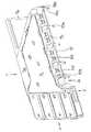
図1〜図7に種々異なる方向から見た図及び詳細で示した、本発明に従って構成された差し込み接続コネクタの第1実施例は、モジュール状に構成されたばねストリップ1である。このばねストリップ1は、右後ろから見た斜視図で示されている。以下の説明を分かりやすくするために、図1にはこのばねストリップを見る方向に関連した3軸線による交差線が示されている。この交差線「RK」に付けられた符号は次のような意味を有している。
「V]:差し込み接続コネクタを前から見た方向
「H]:差し込み接続コネクタを後ろから見た方向
「L]:差し込み接続コネクタを左から見た方向
「R]:差し込み接続コネクタを右から見た方向
「O」:差し込み接続コネクタを上から見た方向
「U」:差し込み接続コネクタを下からみた方向Hereinafter, the present invention will be described in detail with reference to the embodiments shown in the drawings, and other advantages of the present invention will be described. The drawing is shown schematically,
A first embodiment of a bayonet connector constructed according to the invention, shown in different views and in detail in FIGS. 1 to 7, is a spring strip 1 constructed in a modular manner. The spring strip 1 is shown in a perspective view from the right rear. For ease of understanding the following description, FIG. 1 shows a triaxial cross line associated with the direction of viewing the spring strip. The code | symbol attached | subjected to this intersection line "RK" has the following meaning.
"V": Direction of plug connector viewed from the front "H": Direction of plug connector viewed from the rear "L": Direction of plug connector viewed from the left "R": Plug connector viewed from the right Direction “O”: Direction of plug connector viewed from above “U”: Direction of plug connector viewed from below
差し込み接続コネクタ1は、図面では、その固定側3cで以て、プリント基板8の実装面8a上に載設されていて、はんだ付けによる固定が準備されている。この差し込み接続コネクタ1は、互いに相並んで配置された複数のばねストリップディスク7より成っており、これらのばねストリップディスク(Federleistenscheiben)7は、複数部分より成る共通のケーシング3によって目標位置で互いに当接し合って保持される。差し込み接続コネクタ1の正面側が符号3aによって示されている。この正面側は、対応して構成されたナイフストリップと解除可能に差し込み接続される、差し込み接続コネクタ1の接続側である。ケーシング3の後ろ側は、図1では符号3bで示されている。 In the drawing, the plug-in connector 1 is mounted on the mounting surface 8a of the printed
各ばねストリップディスク7はベース体7aより成っており、このベース体7a内に複数の受容チャンネル7bが互いに間隔を保って配置されている。これらの受容チャンネル7b内に、それぞれ1つのばねクリップ接点5が位置決めされている。受容チャンネル7bは、差し込み接続コネクタ1のケーシング3の正面側3a及び固定側3cに向かって開放している。ばねクリップ接点5は、接続区分5aと中央区分5bと固定区分5cとを有している。固定区分5cは端部側でSMD基部5dとして構成されており、このSMD基部5dは、各ばねクリップ接点5を位置決め及び固定した後で、固定側3cにおいてばねストリップディスク7のベース体7aから突き出している。ばねクリップ接点5を挿入した後で、受容チャンネル7bを閉鎖するためにカバー7cが設けられており、このカバー7cは、有利には環状に延在する切欠内に挿入されているので、カバー7cは、ベース体7aの当該の側面を越えて突き出すことはない。ベース体7aの、カバー7cとは反対側において、ばねストリップディスク7内に位置決めされたばねクリップ接点5を電気的に遮蔽するためのシールドプレート10がベース体7aに当接せしめられる。このシールドプレート10をベース体7aにおいて位置決めするために、ベース体7aに少なくとも1つのスリット状の切欠7dが設けられており、この切欠7dは、図示の有利な実施例ではベース体7aの両側面を貫通している。これに対応して、シールドプレート10には少なくとも1つの部分区分が折り曲げられており、この部分区分は、ベース体7aに形成された前記切欠7d内に係合する。 Each
遮蔽効果を高めるために、ベース体7aに複数の切欠7dが設けられていて、これに対応してシールドプレート10に、複数の折り曲げられた部分区分が設けられており、これらの折り曲げられた部分は、折り曲げられたウエブ10eである(図5参照)。図7では見えないので、幾つかの切欠7dは図示されていない。 In order to enhance the shielding effect, the base body 7a is provided with a plurality of
本発明のその他の変化実施例の特別な構成は、少なくとも2つの折り曲げられたウエブ10eが、そのシールドエレメントとしての本来の機能の他に、戻り止めフックとして構成されていて、ばねストリップディスク7のベース体7aの切欠7d内に係合する。これによって、ばねクリップ接点5に作用する引き抜き力がさらに、プリント基板8に接続された固定ピン10aに良好にガイドされる。それについては以下に詳しく説明されている。 A special configuration of another variant of the invention is that at least two folded
ベース体7aの切欠7dの位置、及びこれに対応する、シールドプレートにおける折り曲げられたウエブ10aの位置は、ばねクリップ接点5のための受容チャンネル7bが、それぞれのばねストリップディスク7自体において少なくとも3方側が遮蔽されるように、選定されている。各受容チャンネル7bの第4の側の遮蔽は、隣接して配置されたばねストリップディスク7のシールドプレート10によって行われる。このシールドプレート10は、当該のばねストリップディスク7のカバー7cに向けられている。それぞれのばねストリップディスク7に設けられたシールドプレート10は、その固定側に位置する本体縁部10dで、同じ本体平面に突き出す少なくとも1つの固定ピン10aを有している。図示の実施例では、所定のラスタ(格子)状に配置された当該の本体縁部10dに亘って分配配置された5つの固定ピン10aである(図5参照)。これらの固定ピン10aは、プリント基板8の実装面8a上に載設されたばねストリップ1においてそれぞれ1つの貫通孔8b内に挿入されており(図4参照)、これらの貫通孔8bは、プリント基板8に実装面8aの側から所定のラスタ状に形成されている。 The position of the
新規な特別な構成において、前記本体縁部10dの側面端部に配置された固定ピン10aは、それぞれ少なくとも1つの突出する付加部10bを有している。ばねストリップディスク7のシールドプレート10の外側の2つの固定ピン10aに設けられたこのような付加部10bによって、ばねストリップ1がプリント基板8の実装面8a上に載せられた状態で、当該のばねストリップディスク7に位置決めされ、かつ固定されたばねクリップ接点5のSMD基部5dは、はんだ付けの前に、プリント基板8の実装面8aから所定の間隔「a」を保って配置されている。これによって、ばねクリップ接点5の固定区分5cのすべての端部が、所定のわずかな公差範囲内で、プリント基板8の実装面8a上に設けられた(図示していない)導体路に対して同一平面上に位置することが保証され、これによって良好なSMTデザインが保証される。それぞれ導体路8の貫通孔8b内に突入する固定ピン10aは、THR技術によってプリント基板8に接続される。これによって、確実な引張負荷軽減を有する頑丈な差し込み接続のためのアース接続が得られる。つまり、高い機械的な形状安定性を有する接続部が得られる。これは、コーナープラグ、つまり接続側3aが固定側3c(実装側)に対して90゜を成している差し込み接続コネクタにおいて特に有利である。 In a new special configuration, each of the fixing pins 10a arranged at the side end of the
シールドプレート10の構成における特に有利な実施例では、スペーサ部材として作用する付加部10bが固定ピン10aの両側に設けられている。必要であれば、つまりHF技術のパラメータに関連して相応の規定において、第2の付加部10bは短縮して構成されているので、付加部10cが形成され、それによって、付加的にプリント基板8内においてTHR技術で当該の固定ピン10aを固定するために、信号を伝達するばねクリップ接点5におけるように、この短縮された負荷部10cをSMT技術でプリント基板に接続することができる。しかしながら、このような構成は特別なユーザーの要望に基づいて設計されている。 In a particularly advantageous embodiment in the configuration of the
シールドプレート10において折り曲げられたウエブ10eによって生じた開口は、特に非常に高いデータ率(10GBit/s以上)で伝送する場合に、場合によっては不都合である。従って、以上述べた構成に対して補足的に、ばねストリップディスク7のベース体7aにシールドプレート10を組み付ける前に、別のシールドプレート、電気的に遮蔽するプレート12が設けられており、このプレート12の外側の本体輪郭形状12bは、シールドプレート10の当該部分領域に相当する。さらに内側のプレート12は、複数の切欠12aを有している。これらの切欠12aを通して、シールドプレート10のウエブ10eが差し込まれるようになっている(図5a,図5b)。シールドプレート10に「内側」から当て付けられるプレート12は、該シールドプレート10の前記開口を閉鎖する。 The opening produced by the
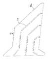
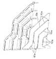
図2及び図3には、差し込み接続コネクタ1のばねストリップディスク7(図1参照)の左側から見た斜視図、及び右側から見た斜視図が示されている。図2及び図3から、図1乃至図7に示したモジュール状に構成された差し込み接続コネクタ1において、ばねクリップ接点5及びシールドプレート10の固定側3cの接続部が、互いに間隔を保って2列に配置されている、ことが分かる。 2 and 3 are a perspective view seen from the left side and a perspective view seen from the right side of the spring strip disk 7 (see FIG. 1) of the plug-in connector 1. 2 and 3, in the plug-in connector 1 configured in the module shape shown in FIGS. 1 to 7, the
図示していない本発明の別の構成によれば、固定ピン10aが本体縁部10d(本体縁部10dから固定ピン10aが突出している)に関連して、90゜だけ2回折り曲げられており、それによって、プリント基板に係合する、固定ピン10aの区分が、ばねクリップ接点5のSMD基部5dと一列を成している。それによって、ばねストリップディスク7の厚さを相応に構成すれば、所定の面上に多数の接点を配置することができる。 According to another configuration of the present invention which is not shown, the fixing
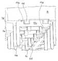
本発明に従って構成された差し込み接続コネクタの第2実施例は図8〜図10に示されている。第2実施例では、ナイフストリップ9が設けられており、このナイフストリップ9は、例えば前記ばねストリップ1と電気的な単数又は複数の接続を形成するために差し込み可能、つまりばねストリップ1と共に差し込み接続コネクタを形成することができる。図8〜図10に示したナイフストリップにおいては、ピン接点6を電気的に遮蔽するためにシールドプロフィール部11が設けられており、このシールドプロフィール部11はそれぞれ1対のピン接点6によって3方側が包囲されている。これらのピン接点6は、それぞれ1つの接続区分6aを有しており、この接続区分6aは、ナイフストリップ9とばねストリップ1とが差し込み結合されると、ばねストリップディスク7のばねクリップ接点5の接続区分5a内に係合する。中央区分6bによって、各ピン接点6は、ナイフストリップ9の底部にプレス嵌めで保持されている。この底部から、固定区分6cが突き出しており、この固定区分6cの端部はSMD基部6dとして構成されている。図示の実施例ではベース体9aの組み立て側で側方に設けられたスペーサ部分9eによって、組み立て及びSMT固定のために確保しようとする、プリント基板8の実装面8aと各SMD足部6dの下側面との間の間隔が得られる。符号9dによって示された、ナイフストリップ9のベース体9aの開口によって、ナイフストリップ9が、差し込み接続コネクタ1のケーシング3の正面側3a内に確実に導入される。内側の底面9cから上方「O]に向かって突き出す、シールドプロフィール部11の部分は符号11aで示されている。ベース体9aの外側の底面から突き出す、各シールドプロフィール部11の下側の区分は、プリント基板の実装面に接続される接点区分11cである。接続区分11aと接点区分11cとの間にガイド区分11bが設けられており、このガイド区分11bは、ベース体9aの底部を貫通係合し、このベース体9a内でプレス嵌めによって保持される。予測不能であるが、場合によっては発生する引き出し力に対抗するために、接点区分11cからガイド区分11bへの移行領域内に、少なくとも1つの本体面から側方に突き出すストッパ11fが設けられており、このストッパ11fは、外側の底面9dに当接する。シールドプロフィール部11の接点区分11cの下部領域は、一方側が固定ピン11eとして構成されていて、他方側がSMD足部11dとして構成されている。このような構成によって、ナイフストリップ9が一方ではHF技術による利点を利用しながらSMT技術によってプリント基板上に固定することができ、しかもそれと同時に固定ピン10eをTHR技術でプリント基板8に接続することによって、必要な高い機械的な形状安定性が得られる。 A second embodiment of a bayonet connector constructed in accordance with the present invention is shown in FIGS. In a second embodiment, a
1 差し込み接続コネクタ(モジュール状に構成されたばねストリップ)、 3 差し込み接続コネクタ1のケーシング、 3a 正面側、 3b 後ろ側、 3c 固定側、 5 ばねクリップ接点、 5a 接続区分、 5b 中央区分、 5c 固定区分、 5d SMD基部、 6 ピン接点、 6a 接続区分、 6b 中央区分、 6c 固定区分、 6d SMD基部、 7 ばねストリップディスク(ばねストリップモジュール)、 7a ベース体、 7b 受容チャンネル、 7c カバー、 7d スリット状の切欠、 8 プリント基板、 8a 実装面、 8b 貫通孔、 9 ナイフストリップ(差し込み接続コネクタ)、 9a ベース体、 9b 開口、 9c 内側の底面、 9d スペーサ部分、 10 シールドプレート、 10a 固定ピン、 10b 付加部、 10c 短縮された付加部、 10d 固定側の本体縁部、 10e 折り曲げられたウエブ、 11 シールドプロフォール部、 11a 接続区分、 11b ガイド区分、 11c 接点区分、 11d SMD基部、 11e 固定ピン、 11f ストッパ、 12 電気的に遮蔽するプレート、 12a 切欠、 a 実装面8aとSMD基部5bとの間の間隔、 Rk 差し込み接続コネクタの本体面を上から見た方向を示す方向交差線、 V 前、 H 後、 L 左、 R 右、 O 上、 U 下 DESCRIPTION OF SYMBOLS 1 Insertion connector (Spring strip comprised in the shape of a module), 3 Casing of insertion connector 1, 3a Front side, 3b Back side, 3c Fixed side, 5 Spring clip contact, 5a Connection division, 5b Central division,
Claims (16)
Translated fromJapaneseケーシング(3;4)が設けられていて、該ケーシングの外側及び内側に、差し込み接続コネクタの構成部分が位置決めされ、かつ固定されており、
信号を伝送するための電気的な接点部分(5;6)が設けられていて、これらの接点部分(5;6)は、一端部で接続区分(5a;6a)を有していて、他端部で導電性の固定区分(5c;6c)を有しており、
電気的な遮蔽部材(10;11)が設けられていて、これらの遮蔽部材が、少なくとも1つの導電性の接点区分を有しており、
組み立て側で前記ケーシングから突き出す、電気的な接点部分(5;6)の固定区分(5c;6c)と、前記電気的な遮蔽部材(10;11)の接点区分とが、所定の格子状に配置されていて、はんだ付けによって前記プリント基板(8)と接続可能である形式のものにおいて、
電気的な接点部分(5;6)の導電性の固定区分(5c;6c)の自由端部がSMD接点(6d;11d)であって、前記遮蔽部材(10;11)の少なくとも1つの導電性の接点区分が同時に固定ピン(10a;11e)であって、該固定ピンが、プリント基板(8)上に差し込み接続コネクタを配置した時に、THR技術によるはんだ接続を実施するために、このプリント基板(8)の貫通孔内に突入することを特徴とする、遮蔽部材を備えた4極多列型の差し込み接続コネクタ。A four-pole multi-row plug-in connector with a shielding member for placement on printed circuit boards, circuit cards and equivalent electrical elements that can be fitted into an electrical or electronic system. ,at least,
A casing (3; 4) is provided, the components of the plug connector are positioned and fixed on the outside and inside of the casing,
Electrical contact parts (5; 6) for transmitting signals are provided, these contact parts (5; 6) have a connection section (5a; 6a) at one end and the other It has a conductive fixed section (5c; 6c) at the end,
Electrical shielding members (10; 11) are provided, these shielding members having at least one conductive contact section;
The fixed section (5c; 6c) of the electrical contact portion (5; 6) and the contact section of the electrical shielding member (10; 11) projecting from the casing on the assembly side are in a predetermined lattice shape. In a type that is arranged and can be connected to the printed circuit board (8) by soldering,
The free end of the conductive fixed section (5c; 6c) of the electrical contact portion (5; 6) is an SMD contact (6d; 11d), and at least one conductive of the shielding member (10; 11) The contact point of the sex is at the same time a fixing pin (10a; 11e), which when the fixing pin is placed on the printed circuit board (8) with a plug connector, this printed circuit board is used to carry out a solder connection by THR technology. A four-pole multi-row plug-in connector provided with a shielding member, which is inserted into a through hole of a substrate (8).
Applications Claiming Priority (2)
| Application Number | Priority Date | Filing Date | Title |
|---|---|---|---|
| DE202005020474UDE202005020474U1 (en) | 2005-12-31 | 2005-12-31 | Connectors |
| DE202005020474.9 | 2005-12-31 |
Publications (2)
| Publication Number | Publication Date |
|---|---|
| JP2007184276Atrue JP2007184276A (en) | 2007-07-19 |
| JP4758885B2 JP4758885B2 (en) | 2011-08-31 |
Family
ID=36012322
Family Applications (1)
| Application Number | Title | Priority Date | Filing Date |
|---|---|---|---|
| JP2006354732AActiveJP4758885B2 (en) | 2005-12-31 | 2006-12-28 | Plug-in connector |
Country Status (3)
| Country | Link |
|---|---|
| US (1) | US7267515B2 (en) |
| JP (1) | JP4758885B2 (en) |
| DE (1) | DE202005020474U1 (en) |
Cited By (4)
| Publication number | Priority date | Publication date | Assignee | Title |
|---|---|---|---|---|
| JP2010044975A (en)* | 2008-08-15 | 2010-02-25 | Fujitsu Component Ltd | Connector, and mounting structure of connector |
| JP2011082048A (en)* | 2009-10-08 | 2011-04-21 | Fujitsu Component Ltd | Male connector, connector, and backplane |
| JP2015167136A (en)* | 2009-11-06 | 2015-09-24 | モレックス インコーポレイテドMolex Incorporated | Multi-layer circuit member and assembly therefor |
| JP2017520896A (en)* | 2014-07-14 | 2017-07-27 | エルニ プロダクション ゲゼルシャフト ミット ベシュレンクテル ハフツング ウント コンパニー コマンディトゲゼルシャフト | Plug connector and components |
Families Citing this family (121)
| Publication number | Priority date | Publication date | Assignee | Title |
|---|---|---|---|---|
| JP3909769B2 (en)* | 2004-01-09 | 2007-04-25 | 日本航空電子工業株式会社 | connector |
| NL1027044C2 (en)* | 2004-09-15 | 2006-03-16 | Framatome Connectors Int | Connector and connector assembly comprising conduits with at least one opening. |
| DE102006036917A1 (en)* | 2006-08-04 | 2008-02-14 | Erni Electronics Gmbh | Multipole connector |
| DE102006039817A1 (en) | 2006-08-25 | 2008-03-13 | Erni Electronics Gmbh | Component for connecting to a second component |
| US7351115B1 (en)* | 2007-01-17 | 2008-04-01 | International Business Machines Corporation | Method for modifying an electrical connector |
| MY148711A (en)* | 2007-06-20 | 2013-05-31 | Molex Inc | Mezzanine-style connector with serpentine ground structure |
| US20090017681A1 (en)* | 2007-06-20 | 2009-01-15 | Molex Incorporated | Connector with uniformly arrange ground and signal tail portions |
| WO2008156855A2 (en) | 2007-06-20 | 2008-12-24 | Molex Incorporated | Connector with serpentine groung structure |
| WO2008156857A2 (en)* | 2007-06-20 | 2008-12-24 | Molex Incorporated | Backplane connector with improved pin header |
| CN101779342B (en)* | 2007-06-20 | 2013-09-25 | 莫列斯公司 | Connector with bifurcated contact arms |
| CN101779340B (en)* | 2007-06-20 | 2013-02-20 | 莫列斯公司 | Impedance control in connector mounting areas |
| JP4421644B2 (en)* | 2007-09-11 | 2010-02-24 | ヒロセ電機株式会社 | Intermediate electrical connector |
| US7585186B2 (en)* | 2007-10-09 | 2009-09-08 | Tyco Electronics Corporation | Performance enhancing contact module assemblies |
| US20090163047A1 (en)* | 2007-12-24 | 2009-06-25 | Myoungsoo Jeon | Connector having both press-fit pins and high-speed conductive resilient surface contact elements |
| CN201196992Y (en)* | 2008-01-29 | 2009-02-18 | 富士康(昆山)电脑接插件有限公司 | Electric Connector |
| JP5054569B2 (en)* | 2008-02-28 | 2012-10-24 | 富士通コンポーネント株式会社 | connector |
| US7748997B2 (en)* | 2008-07-22 | 2010-07-06 | Tyco Electronics Corporation | Receptacle for electrical connectors |
| US7690946B2 (en)* | 2008-07-29 | 2010-04-06 | Tyco Electronics Corporation | Contact organizer for an electrical connector |
| US7775802B2 (en) | 2008-12-05 | 2010-08-17 | Tyco Electronics Corporation | Electrical connector system |
| US8167651B2 (en) | 2008-12-05 | 2012-05-01 | Tyco Electronics Corporation | Electrical connector system |
| US7819697B2 (en)* | 2008-12-05 | 2010-10-26 | Tyco Electronics Corporation | Electrical connector system |
| US7976318B2 (en) | 2008-12-05 | 2011-07-12 | Tyco Electronics Corporation | Electrical connector system |
| US8366485B2 (en) | 2009-03-19 | 2013-02-05 | Fci Americas Technology Llc | Electrical connector having ribbed ground plate |
| US7988491B2 (en)* | 2009-12-11 | 2011-08-02 | Tyco Electronics Corporation | Electrical connector having contact modules |
| TWI505579B (en)* | 2009-12-18 | 2015-10-21 | Tyco Electronics Corp | Electrical connector system |
| TWI519011B (en)* | 2009-12-29 | 2016-01-21 | 太谷電子公司 | Electrical connector system |
| JP2011159470A (en)* | 2010-01-29 | 2011-08-18 | Fujitsu Component Ltd | Male connector, female connector, and connector |
| TWI580122B (en)* | 2010-02-26 | 2017-04-21 | 太谷電子公司 | Electrical connector system |
| US7976340B1 (en) | 2010-03-12 | 2011-07-12 | Tyco Electronics Corporation | Connector system with electromagnetic interference shielding |
| CN107069274B (en) | 2010-05-07 | 2020-08-18 | 安费诺有限公司 | High performance cable connector |
| US8187035B2 (en)* | 2010-05-28 | 2012-05-29 | Tyco Electronics Corporation | Connector assembly |
| JP2011249279A (en)* | 2010-05-31 | 2011-12-08 | Fujitsu Component Ltd | Connector |
| US8157595B2 (en)* | 2010-07-13 | 2012-04-17 | Tyco Electronics Corporation | Ground shield for an electrical connector |
| WO2012031638A1 (en)* | 2010-09-06 | 2012-03-15 | Fci | Shielded electrical connector |
| US8469745B2 (en)* | 2010-11-19 | 2013-06-25 | Tyco Electronics Corporation | Electrical connector system |
| US8308512B2 (en)* | 2011-01-17 | 2012-11-13 | Tyco Electronics Corporation | Connector assembly |
| US8382520B2 (en)* | 2011-01-17 | 2013-02-26 | Tyco Electronics Corporation | Connector assembly |
| US10243284B2 (en) | 2011-01-31 | 2019-03-26 | Amphenol Corporation | Multi-stage beam contacts |
| WO2012106554A2 (en) | 2011-02-02 | 2012-08-09 | Amphenol Corporation | Mezzanine connector |
| US8430691B2 (en)* | 2011-07-13 | 2013-04-30 | Tyco Electronics Corporation | Grounding structures for header and receptacle assemblies |
| DE102011115505B4 (en)* | 2011-10-11 | 2014-09-11 | Erni Production Gmbh & Co. Kg | Plug element for contacting a printed circuit board and method for its preparation |
| US8690604B2 (en)* | 2011-10-19 | 2014-04-08 | Tyco Electronics Corporation | Receptacle assembly |
| US8845365B2 (en) | 2011-12-08 | 2014-09-30 | Tyco Electronics Corporation | Cable header connector |
| US8517765B2 (en) | 2011-12-08 | 2013-08-27 | Tyco Electronics Corporation | Cable header connector |
| US8449329B1 (en) | 2011-12-08 | 2013-05-28 | Tyco Electronics Corporation | Cable header connector having cable subassemblies with ground shields connected to a metal holder |
| US8449330B1 (en) | 2011-12-08 | 2013-05-28 | Tyco Electronics Corporation | Cable header connector |
| EP2624034A1 (en) | 2012-01-31 | 2013-08-07 | Fci | Dismountable optical coupling device |
| USD727852S1 (en) | 2012-04-13 | 2015-04-28 | Fci Americas Technology Llc | Ground shield for a right angle electrical connector |
| US8944831B2 (en) | 2012-04-13 | 2015-02-03 | Fci Americas Technology Llc | Electrical connector having ribbed ground plate with engagement members |
| US9257778B2 (en) | 2012-04-13 | 2016-02-09 | Fci Americas Technology | High speed electrical connector |
| USD727268S1 (en) | 2012-04-13 | 2015-04-21 | Fci Americas Technology Llc | Vertical electrical connector |
| USD718253S1 (en) | 2012-04-13 | 2014-11-25 | Fci Americas Technology Llc | Electrical cable connector |
| US9543703B2 (en) | 2012-07-11 | 2017-01-10 | Fci Americas Technology Llc | Electrical connector with reduced stack height |
| USD751507S1 (en) | 2012-07-11 | 2016-03-15 | Fci Americas Technology Llc | Electrical connector |
| US9240644B2 (en) | 2012-08-22 | 2016-01-19 | Amphenol Corporation | High-frequency electrical connector |
| US8771017B2 (en)* | 2012-10-17 | 2014-07-08 | Tyco Electronics Corporation | Ground inlays for contact modules of receptacle assemblies |
| USD745852S1 (en) | 2013-01-25 | 2015-12-22 | Fci Americas Technology Llc | Electrical connector |
| USD720698S1 (en) | 2013-03-15 | 2015-01-06 | Fci Americas Technology Llc | Electrical cable connector |
| CN203218619U (en)* | 2013-03-26 | 2013-09-25 | 连展科技电子(昆山)有限公司 | Socket electrical connector inhabiting crosstalk |
| CN103280670A (en)* | 2013-05-17 | 2013-09-04 | 连展科技电子(昆山)有限公司 | Socket electric connector for inhibiting signal interference |
| JP6089966B2 (en)* | 2013-05-27 | 2017-03-08 | 富士通株式会社 | connector |
| US9548570B2 (en) | 2013-07-23 | 2017-01-17 | Molex, Llc | Direct backplane connector |
| CN103606787B (en)* | 2013-09-13 | 2018-05-22 | 连展科技电子(昆山)有限公司 | Inhibit the electric connector for socket of crosstalk |
| CN104466546B (en)* | 2013-09-17 | 2017-01-11 | 通普康电子(昆山)有限公司 | Communication connection device and lead frame group thereof |
| US9142896B2 (en)* | 2013-11-15 | 2015-09-22 | Tyco Electronics Corporation | Connector assemblies having pin spacers with lugs |
| CN115411547A (en)* | 2014-01-22 | 2022-11-29 | 安费诺有限公司 | Electrical connector, subassembly, module, cable assembly, electrical assembly and circuit board |
| US10396481B2 (en) | 2014-10-23 | 2019-08-27 | Fci Usa Llc | Mezzanine electrical connector |
| US9685736B2 (en)* | 2014-11-12 | 2017-06-20 | Amphenol Corporation | Very high speed, high density electrical interconnection system with impedance control in mating region |
| JP6423281B2 (en)* | 2015-02-18 | 2018-11-14 | ヒロセ電機株式会社 | Connection blade and electrical connector having connection blade |
| CN108701922B (en) | 2015-07-07 | 2020-02-14 | Afci亚洲私人有限公司 | Electrical connector |
| TWI754439B (en) | 2015-07-23 | 2022-02-01 | 美商安芬諾Tcs公司 | Connector, method of manufacturing connector, extender module for connector, and electric system |
| TWI648925B (en)* | 2015-12-14 | 2019-01-21 | 莫仕有限公司 | Backplane connector and connector system |
| WO2017201170A1 (en) | 2016-05-18 | 2017-11-23 | Amphenol Corporation | Controlled impedance edged coupled connectors |
| TWI746561B (en) | 2016-05-31 | 2021-11-21 | 美商安芬諾股份有限公司 | High performance cable termination |
| CN106410473A (en)* | 2016-06-22 | 2017-02-15 | 欧品电子(昆山)有限公司 | High-speed connector assembly, and socket connector and socket terminal thereof |
| CN112151987B (en) | 2016-08-23 | 2022-12-30 | 安费诺有限公司 | Configurable high performance connector |
| CN106207640A (en)* | 2016-08-26 | 2016-12-07 | 江苏银佳企业集团有限公司 | A kind of drawer docking apparatus of band communication interface |
| CN110088985B (en) | 2016-10-19 | 2022-07-05 | 安费诺有限公司 | Flexible shield for ultra-high speed high density electrical interconnects |
| US9831608B1 (en)* | 2016-10-31 | 2017-11-28 | Te Connectivity Corporation | Electrical connector having ground shield that controls impedance at mating interface |
| DE102016122263A1 (en)* | 2016-11-18 | 2018-05-24 | Phoenix Contact Gmbh & Co. Kg | Shunting connector and method for producing a jumper connector |
| US10128619B2 (en)* | 2017-01-27 | 2018-11-13 | Te Connectivity Corporation | Ground shield for a contact module |
| US9812817B1 (en)* | 2017-01-27 | 2017-11-07 | Te Connectivity Corporation | Electrical connector having a mating connector interface |
| US10404014B2 (en) | 2017-02-17 | 2019-09-03 | Fci Usa Llc | Stacking electrical connector with reduced crosstalk |
| CN110800172B (en) | 2017-04-28 | 2021-06-04 | 富加宜(美国)有限责任公司 | High frequency BGA connector |
| TWI788394B (en) | 2017-08-03 | 2023-01-01 | 美商安芬諾股份有限公司 | Cable assembly and method of manufacturing the same |
| US10535971B2 (en) | 2017-10-12 | 2020-01-14 | Te Connectivity Corporation | Electrical connector |
| CN114512840B (en) | 2017-10-30 | 2024-06-25 | 安费诺富加宜(亚洲)私人有限公司 | Low crosstalk card edge connector |
| CN110212326B (en)* | 2018-02-28 | 2021-09-03 | 中航光电科技股份有限公司 | Connector assembly and back plate connector and grounding buckle plate thereof |
| US10665973B2 (en) | 2018-03-22 | 2020-05-26 | Amphenol Corporation | High density electrical connector |
| WO2019195319A1 (en) | 2018-04-02 | 2019-10-10 | Ardent Concepts, Inc. | Controlled-impedance compliant cable termination |
| TWI668927B (en)* | 2018-04-03 | 2019-08-11 | 慶良電子股份有限公司 | Electrical connector and transsmitting wafer thereof |
| CN208862209U (en) | 2018-09-26 | 2019-05-14 | 安费诺东亚电子科技(深圳)有限公司 | A connector and its applied PCB board |
| CN113169484A (en) | 2018-10-09 | 2021-07-23 | 安费诺商用电子产品(成都)有限公司 | High density edge connector |
| CN109638531A (en)* | 2018-10-23 | 2019-04-16 | 浙江舟电子科技股份有限公司 | One kind surpassing six type shielding information socket modules |
| TWM576774U (en) | 2018-11-15 | 2019-04-11 | 香港商安費諾(東亞)有限公司 | Metal case with anti-displacement structure and connector thereof |
| US10931062B2 (en) | 2018-11-21 | 2021-02-23 | Amphenol Corporation | High-frequency electrical connector |
| US11381015B2 (en) | 2018-12-21 | 2022-07-05 | Amphenol East Asia Ltd. | Robust, miniaturized card edge connector |
| WO2020154507A1 (en) | 2019-01-25 | 2020-07-30 | Fci Usa Llc | I/o connector configured for cable connection to a midboard |
| US11101611B2 (en) | 2019-01-25 | 2021-08-24 | Fci Usa Llc | I/O connector configured for cabled connection to the midboard |
| CN111585098B (en) | 2019-02-19 | 2025-08-19 | 安费诺有限公司 | High-speed connector |
| WO2020172395A1 (en) | 2019-02-22 | 2020-08-27 | Amphenol Corporation | High performance cable connector assembly |
| TWM582251U (en) | 2019-04-22 | 2019-08-11 | 香港商安費諾(東亞)有限公司 | Connector set with hidden locking mechanism and socket connector thereof |
| TW202448032A (en) | 2019-05-20 | 2024-12-01 | 美商安芬諾股份有限公司 | Connector module, connector, electronic assembly, electrical connector and wafer of connector module |
| TWI743813B (en)* | 2019-05-31 | 2021-10-21 | 美商莫仕有限公司 | Electric connector assembly and connector system |
| CN114788097A (en) | 2019-09-19 | 2022-07-22 | 安费诺有限公司 | High speed electronic system with midplane cable connector |
| US11799230B2 (en) | 2019-11-06 | 2023-10-24 | Amphenol East Asia Ltd. | High-frequency electrical connector with in interlocking segments |
| US11588277B2 (en) | 2019-11-06 | 2023-02-21 | Amphenol East Asia Ltd. | High-frequency electrical connector with lossy member |
| TWI887339B (en) | 2020-01-27 | 2025-06-21 | 美商Fci美國有限責任公司 | High speed, high density direct mate orthogonal connector |
| WO2021154702A1 (en) | 2020-01-27 | 2021-08-05 | Fci Usa Llc | High speed connector |
| CN113258325A (en) | 2020-01-28 | 2021-08-13 | 富加宜(美国)有限责任公司 | High-frequency middle plate connector |
| US11652307B2 (en) | 2020-08-20 | 2023-05-16 | Amphenol East Asia Electronic Technology (Shenzhen) Co., Ltd. | High speed connector |
| CN212874843U (en) | 2020-08-31 | 2021-04-02 | 安费诺商用电子产品(成都)有限公司 | Electrical connector |
| CN215816516U (en) | 2020-09-22 | 2022-02-11 | 安费诺商用电子产品(成都)有限公司 | Electrical connector |
| CN213636403U (en) | 2020-09-25 | 2021-07-06 | 安费诺商用电子产品(成都)有限公司 | Electrical connector |
| US12176650B2 (en) | 2021-05-05 | 2024-12-24 | Amphenol East Asia Limited (Hong Kong) | Electrical connector with guiding structure and mating groove and method of connecting electrical connector |
| CN113809597B (en)* | 2021-08-11 | 2024-08-06 | 中航光电科技股份有限公司 | A snap-fit structure and a connector using the same |
| CN215266741U (en) | 2021-08-13 | 2021-12-21 | 安费诺商用电子产品(成都)有限公司 | High-performance card connector meeting high-bandwidth transmission |
| USD1002553S1 (en) | 2021-11-03 | 2023-10-24 | Amphenol Corporation | Gasket for connector |
| USD1067191S1 (en) | 2021-12-14 | 2025-03-18 | Amphenol Corporation | Electrical connector |
| USD1068685S1 (en) | 2021-12-14 | 2025-04-01 | Amphenol Corporation | Electrical connector |
| DE102023127951A1 (en)* | 2023-10-12 | 2025-04-17 | Te Connectivity Solutions Gmbh | Electrical connector |
Citations (7)
| Publication number | Priority date | Publication date | Assignee | Title |
|---|---|---|---|---|
| JPH03233879A (en)* | 1989-10-10 | 1991-10-17 | Amp Inc | Electric connector assembly |
| WO2001029931A1 (en)* | 1999-10-18 | 2001-04-26 | Erni Elektroapparate Gmbh | Shielded plug-in connector |
| WO2001057961A1 (en)* | 2000-02-03 | 2001-08-09 | Teradyne, Inc. | Connector with shielding |
| JP2004521448A (en)* | 2001-01-25 | 2004-07-15 | テラダイン・インコーポレーテッド | Connector molding method and shielded wafer type connector made by the same method |
| US6808420B2 (en)* | 2002-05-22 | 2004-10-26 | Tyco Electronics Corporation | High speed electrical connector |
| JP2005032529A (en)* | 2003-07-10 | 2005-02-03 | Jst Mfg Co Ltd | High-speed transmission connector |
| US6872085B1 (en)* | 2003-09-30 | 2005-03-29 | Teradyne, Inc. | High speed, high density electrical connector assembly |
Family Cites Families (11)
| Publication number | Priority date | Publication date | Assignee | Title |
|---|---|---|---|---|
| US5702258A (en)* | 1996-03-28 | 1997-12-30 | Teradyne, Inc. | Electrical connector assembled from wafers |
| US6146202A (en)* | 1998-08-12 | 2000-11-14 | Robinson Nugent, Inc. | Connector apparatus |
| US6231391B1 (en)* | 1999-08-12 | 2001-05-15 | Robinson Nugent, Inc. | Connector apparatus |
| NL1013740C2 (en)* | 1999-12-03 | 2001-06-06 | Fci S Hertogenbosch B V | Shielded connector. |
| US6364710B1 (en)* | 2000-03-29 | 2002-04-02 | Berg Technology, Inc. | Electrical connector with grounding system |
| US6347962B1 (en)* | 2001-01-30 | 2002-02-19 | Tyco Electronics Corporation | Connector assembly with multi-contact ground shields |
| US6461202B2 (en)* | 2001-01-30 | 2002-10-08 | Tyco Electronics Corporation | Terminal module having open side for enhanced electrical performance |
| US6899566B2 (en)* | 2002-01-28 | 2005-05-31 | Erni Elektroapparate Gmbh | Connector assembly interface for L-shaped ground shields and differential contact pairs |
| JP3661149B2 (en)* | 2002-10-15 | 2005-06-15 | 日本航空電子工業株式会社 | Contact module |
| US7094102B2 (en)* | 2004-07-01 | 2006-08-22 | Amphenol Corporation | Differential electrical connector assembly |
| US7108556B2 (en)* | 2004-07-01 | 2006-09-19 | Amphenol Corporation | Midplane especially applicable to an orthogonal architecture electronic system |
- 2005
- 2005-12-31DEDE202005020474Upatent/DE202005020474U1/ennot_activeExpired - Lifetime
- 2006
- 2006-02-03USUS11/347,065patent/US7267515B2/enactiveActive
- 2006-12-28JPJP2006354732Apatent/JP4758885B2/enactiveActive
Patent Citations (10)
| Publication number | Priority date | Publication date | Assignee | Title |
|---|---|---|---|---|
| JPH03233879A (en)* | 1989-10-10 | 1991-10-17 | Amp Inc | Electric connector assembly |
| WO2001029931A1 (en)* | 1999-10-18 | 2001-04-26 | Erni Elektroapparate Gmbh | Shielded plug-in connector |
| JP2003512706A (en)* | 1999-10-18 | 2003-04-02 | エルニ エレクトロアパラーテ ゲーエムベーハー | Plug-in connection device with shield |
| WO2001057961A1 (en)* | 2000-02-03 | 2001-08-09 | Teradyne, Inc. | Connector with shielding |
| JP2003522385A (en)* | 2000-02-03 | 2003-07-22 | テラダイン・インコーポレーテッド | Connector with shielding |
| JP2004521448A (en)* | 2001-01-25 | 2004-07-15 | テラダイン・インコーポレーテッド | Connector molding method and shielded wafer type connector made by the same method |
| US6808420B2 (en)* | 2002-05-22 | 2004-10-26 | Tyco Electronics Corporation | High speed electrical connector |
| US6913490B2 (en)* | 2002-05-22 | 2005-07-05 | Tyco Electronics Corporation | High speed electrical connector |
| JP2005032529A (en)* | 2003-07-10 | 2005-02-03 | Jst Mfg Co Ltd | High-speed transmission connector |
| US6872085B1 (en)* | 2003-09-30 | 2005-03-29 | Teradyne, Inc. | High speed, high density electrical connector assembly |
Cited By (4)
| Publication number | Priority date | Publication date | Assignee | Title |
|---|---|---|---|---|
| JP2010044975A (en)* | 2008-08-15 | 2010-02-25 | Fujitsu Component Ltd | Connector, and mounting structure of connector |
| JP2011082048A (en)* | 2009-10-08 | 2011-04-21 | Fujitsu Component Ltd | Male connector, connector, and backplane |
| JP2015167136A (en)* | 2009-11-06 | 2015-09-24 | モレックス インコーポレイテドMolex Incorporated | Multi-layer circuit member and assembly therefor |
| JP2017520896A (en)* | 2014-07-14 | 2017-07-27 | エルニ プロダクション ゲゼルシャフト ミット ベシュレンクテル ハフツング ウント コンパニー コマンディトゲゼルシャフト | Plug connector and components |
Also Published As
| Publication number | Publication date |
|---|---|
| US7267515B2 (en) | 2007-09-11 |
| JP4758885B2 (en) | 2011-08-31 |
| DE202005020474U1 (en) | 2006-02-23 |
| US20070155241A1 (en) | 2007-07-05 |
Similar Documents
| Publication | Publication Date | Title |
|---|---|---|
| JP4758885B2 (en) | Plug-in connector | |
| US8221139B2 (en) | Electrical connector having a ground clip | |
| USRE45018E1 (en) | Electrical connector with improved contacts | |
| US5924899A (en) | Modular connectors | |
| US6960103B2 (en) | Connector to be mounted to a board and ground structure of the connector | |
| CA2550486C (en) | Printed board connector for differential signal transmission | |
| JP3149104U (en) | Electrical connector | |
| EP0675573A2 (en) | Card edge connector with combined shielding and voltage drain protection | |
| US7384288B2 (en) | Connector for printed circuit boards stacked one on another | |
| US20060216996A1 (en) | Electrical connector with improved shielding means | |
| US20110263160A1 (en) | Power connector | |
| US20200083648A1 (en) | High speed electrical connector | |
| JP3134262U (en) | Surface mount connector | |
| US20020006744A1 (en) | Flat cable connector | |
| JP2020071954A (en) | Electrical connector and electronic device | |
| US8033861B2 (en) | Electrical connector with improved board lock having elastic portion abutting against optical drive disk | |
| JP2008277020A (en) | Electrical connector and manufacturing method thereof | |
| JPH06501591A (en) | Shielded multipole plug connector | |
| WO1999026321A1 (en) | Shielded electrical connector | |
| US7985080B2 (en) | Electrical connector having auxiliary hold-down arrangement | |
| JP2002184530A (en) | Protection device for protecting electric connector of printed circuit board from electromagnetic interference | |
| JP2006059692A (en) | Card connector | |
| EP0493107A2 (en) | Minature multiple electrical connector | |
| KR20110093838A (en) | Plug-in connector for printed circuit boards | |
| JPH07230858A (en) | Movable connector |
Legal Events
| Date | Code | Title | Description |
|---|---|---|---|
| A621 | Written request for application examination | Free format text:JAPANESE INTERMEDIATE CODE: A621 Effective date:20081208 | |
| A131 | Notification of reasons for refusal | Free format text:JAPANESE INTERMEDIATE CODE: A131 Effective date:20101015 | |
| A601 | Written request for extension of time | Free format text:JAPANESE INTERMEDIATE CODE: A601 Effective date:20110117 | |
| A602 | Written permission of extension of time | Free format text:JAPANESE INTERMEDIATE CODE: A602 Effective date:20110120 | |
| A601 | Written request for extension of time | Free format text:JAPANESE INTERMEDIATE CODE: A601 Effective date:20110215 | |
| A602 | Written permission of extension of time | Free format text:JAPANESE INTERMEDIATE CODE: A602 Effective date:20110218 | |
| A601 | Written request for extension of time | Free format text:JAPANESE INTERMEDIATE CODE: A601 Effective date:20110314 | |
| A602 | Written permission of extension of time | Free format text:JAPANESE INTERMEDIATE CODE: A602 Effective date:20110317 | |
| A521 | Request for written amendment filed | Free format text:JAPANESE INTERMEDIATE CODE: A523 Effective date:20110411 | |
| TRDD | Decision of grant or rejection written | ||
| A01 | Written decision to grant a patent or to grant a registration (utility model) | Free format text:JAPANESE INTERMEDIATE CODE: A01 Effective date:20110525 | |
| A01 | Written decision to grant a patent or to grant a registration (utility model) | Free format text:JAPANESE INTERMEDIATE CODE: A01 | |
| A61 | First payment of annual fees (during grant procedure) | Free format text:JAPANESE INTERMEDIATE CODE: A61 Effective date:20110603 | |
| R150 | Certificate of patent or registration of utility model | Free format text:JAPANESE INTERMEDIATE CODE: R150 Ref document number:4758885 Country of ref document:JP Free format text:JAPANESE INTERMEDIATE CODE: R150 | |
| FPAY | Renewal fee payment (event date is renewal date of database) | Free format text:PAYMENT UNTIL: 20140610 Year of fee payment:3 | |
| R250 | Receipt of annual fees | Free format text:JAPANESE INTERMEDIATE CODE: R250 | |
| R250 | Receipt of annual fees | Free format text:JAPANESE INTERMEDIATE CODE: R250 | |
| R250 | Receipt of annual fees | Free format text:JAPANESE INTERMEDIATE CODE: R250 | |
| R250 | Receipt of annual fees | Free format text:JAPANESE INTERMEDIATE CODE: R250 | |
| R250 | Receipt of annual fees | Free format text:JAPANESE INTERMEDIATE CODE: R250 | |
| R250 | Receipt of annual fees | Free format text:JAPANESE INTERMEDIATE CODE: R250 | |
| R250 | Receipt of annual fees | Free format text:JAPANESE INTERMEDIATE CODE: R250 | |
| R250 | Receipt of annual fees | Free format text:JAPANESE INTERMEDIATE CODE: R250 | |
| R250 | Receipt of annual fees | Free format text:JAPANESE INTERMEDIATE CODE: R250 | |
| R250 | Receipt of annual fees | Free format text:JAPANESE INTERMEDIATE CODE: R250 | |
| R250 | Receipt of annual fees | Free format text:JAPANESE INTERMEDIATE CODE: R250 | |
| R250 | Receipt of annual fees | Free format text:JAPANESE INTERMEDIATE CODE: R250 |