JP2007181631A - Fundus observation device - Google Patents
Fundus observation deviceDownload PDFInfo
- Publication number
- JP2007181631A JP2007181631AJP2006003065AJP2006003065AJP2007181631AJP 2007181631 AJP2007181631 AJP 2007181631AJP 2006003065 AJP2006003065 AJP 2006003065AJP 2006003065 AJP2006003065 AJP 2006003065AJP 2007181631 AJP2007181631 AJP 2007181631A
- Authority
- JP
- Japan
- Prior art keywords
- light
- fundus
- image
- optical path
- unit
- Prior art date
- Legal status (The legal status is an assumption and is not a legal conclusion. Google has not performed a legal analysis and makes no representation as to the accuracy of the status listed.)
- Pending
Links
Images


Landscapes
- Eye Examination Apparatus (AREA)
- Investigating Or Analysing Materials By Optical Means (AREA)
Abstract
Translated fromJapaneseDescription
Translated fromJapanese本発明は、被検眼の眼底を観察するために用いられる眼底観察装置に関する。 The present invention relates to a fundus oculi observation device used for observing the fundus oculi of a subject eye.
眼底観察装置としては、従来から眼底カメラが広く用いられている。図8は、従来の一般的な眼底カメラの外観構成の一例を表し、図9は、眼底カメラに内蔵される光学系の構成の一例を表している(たとえば特許文献1参照。)。なお、「観察」とは、眼底の撮影画像を観察する場合を少なくとも含むものとする(その他、肉眼による眼底観察を含んでもよい。)。 Conventionally, fundus cameras have been widely used as fundus oculi observation devices. FIG. 8 shows an example of the external configuration of a conventional general fundus camera, and FIG. 9 shows an example of the configuration of an optical system built in the fundus camera (see, for example, Patent Document 1). Note that “observation” includes at least a case where a photographed image of the fundus is observed (others may include fundus observation with the naked eye).
まず、図8を参照しつつ、従来の眼底カメラ1000の外観構成について説明する。この眼底カメラ1000は、ベース2上に前後左右方向(水平方向)にスライド可能に搭載された架台3を備えている。この架台3には、検者が各種操作を行うための操作パネル3aとジョイスティック4が設置されている。 First, the external configuration of a
検者は、ジョイスティック4を操作することによって、架台3をベース2上において3次元的に移動させることができる。ジョイスティック4の頂部には、眼底を撮影するときに押下される操作ボタン4aが配置されている。 The examiner can move the
ベース2上には支柱5が立設されている。この支柱5には、被検者の顎部を載置するための顎受け6と、被検眼Eを固視させるための光を発する外部固視灯7とが設けられている。 A
架台3上には、眼底カメラ1000の各種の光学系や制御系を格納する本体部8が搭載されている。なお、制御系は、ベース2や架台3の内部等に設けられていることもあるし、眼底カメラ1000に接続されたコンピュータ等の外部装置に設けられていることもある。 On the
本体部8の被検眼E側(図8の紙面左方向)には、被検眼Eに対峙して配置される対物レンズ部8aが設けられている。また、本体部8の検者側(図8の紙面右方向)には、被検眼Eの眼底を肉眼観察するための接眼レンズ部8bが設けられている。 On the eye E side of the main body 8 (the left direction in FIG. 8), an
更に、本体部8には、被検眼Eの眼底の静止画像を撮影するためのスチルカメラ9と、眼底の静止画像や動画像を撮影するためのテレビカメラ等の撮像装置10とが設けられている。このスチルカメラ9と撮像装置10は、それぞれ本体部8に対して着脱可能に形成されている。 Further, the
スチルカメラ9としては、検査の目的や撮影画像の保存方法などの各種条件に応じて、CCD(Charge Coupled Device)やCMOS(Complementary Metal Oxide Semiconductor)等の撮像素子を搭載したデジタルカメラや、フィルムカメラや、インスタントカメラなどを適宜に装着して使用することができる。本体部8には、このような各種のスチルカメラ9を選択的に装着するための装着部8cが形成されている。 As the still camera 9, a digital camera equipped with an image sensor such as a charge coupled device (CCD) or a complementary metal oxide semiconductor (CMOS), or a film camera, depending on various conditions such as the purpose of inspection and the method of storing a captured image In addition, an instant camera or the like can be appropriately attached and used. The
スチルカメラ9や撮像装置10がデジタル撮像方式のものである場合、これらにより撮影された眼底画像の画像データを、眼底カメラ1000に接続されたコンピュータ等に送信し、その眼底画像をディスプレイに表示させて観察することができる。また、眼底カメラ1000に接続された画像記録装置に画像データを送信してデータベース化し、たとえば電子カルテ作成用の電子データとして用いることができる。 When the still camera 9 or the
また、本体部8の検者側には、タッチパネルモニタ11が設けられている。このタッチパネルモニタ11には、(デジタル方式の)スチルカメラ9や撮像装置10から出力される映像信号に基づいて作成される被検眼Eの眼底画像が表示される。また、このタッチパネルモニタ11には、その画面中央を原点とするxy座標系が眼底画像に重ねて表示されるようになっている。検者が画面上の所望の位置に触れると、その触れた位置に対応する座標値が表示されるようになっている。 A
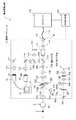
次に、図9を参照しつつ、眼底カメラ1000の光学系の構成について説明する。眼底カメラ1000には、被検眼Eの眼底Efを照明する照明光学系100と、この照明光の眼底反射光を接眼レンズ部8b、スチルカメラ9、撮像装置10に導く撮影光学系120とが設けられている。 Next, the configuration of the optical system of the
照明光学系100は、観察光源101、コンデンサレンズ102、撮影光源103、コンデンサレンズ104、エキサイタフィルタ105及び106、リング透光板107、ミラー108、LCD109、照明絞り110、リレーレンズ111、孔開きミラー112、対物レンズ113を含んで構成されている。 The illumination optical system 100 includes an
観察光源101は、たとえばハロゲンランプにより構成され、眼底観察用の定常光(連続光)を出力する。コンデンサレンズ102は、観察光源101から発せられた定常光(観察照明光)を集光して、観察照明光を眼底にほぼ均等に照明させるための光学素子である。 The
撮影光源103は、たとえばキセノンランプにより構成され、眼底Efの撮影を行うときにフラッシュ発光される。コンデンサレンズ104は、撮影光源103から発せられたフラッシュ光(撮影照明光)を集光して、撮影照明光を眼底Efに均等に照射させるための光学素子である。 The
エキサイタフィルタ105、106は、眼底Efの眼底画像の蛍光撮影を行うときに使用されるフィルタである。このエキサイタフィルタ105、106は、それぞれ、ソレノイド等の駆動機構(図示せず)によって光路上に挿脱可能とされている。エキサイタフィルタ105は、FAG(フルオレセイン蛍光造影)撮影時に光路上に配置される。一方、エキサイタフィルタ106は、ICG(インドシアニングリーン蛍光造影)撮影時に光路上に配置される。なお、カラー撮影時には、エキサイタフィルタ105、106はともに光路上から退避される。 The
リング透光板107は、被検眼Eの瞳孔と共役な位置に配置されており、照明光学系100の光軸を中心としたリング透光部107aを備えている。ミラー108は、観察光源101や撮影光源103が発した照明光を撮影光学系120の光軸方向に反射させる。LCD109は、被検眼Eの固視を行うための固視標(図示せず)などを表示する。 The ring
照明絞り110は、フレア防止等のために照明光の一部を遮断する絞り部材である。この照明絞り110は、照明光学系100の光軸方向に移動可能に構成されており、それにより眼底Efの照明領域を調整できるようになっている。 The
孔開きミラー112は、照明光学系100の光軸と撮影光学系120の光軸とを合成する光学素子である。孔開きミラー112の中心領域には孔部112aが開口されている。照明光学系100の光軸と撮影光学系120の光軸は、この孔部112aの略中心位置にて交差するようになっている。対物レンズ113は、本体部8の対物レンズ部8a内に設けられている。 The
このような構成を有する照明光学系100は、以下のような態様で眼底Efを照明する。まず、眼底観察時には観察光源101が点灯されて観察照明光が出力される。この観察照明光は、コンデンサレンズ102、104を介してリング透光板107を照射する(エキサイタフィルタ105、106は光路上から退避されている。)。リング透光板107のリング透光部107aを通過した光は、ミラー108により反射され、LCD109、照明絞り110及びリレーレンズ111を経由して孔開きミラー112により反射される。孔開きミラー112により反射された観察照明光は、撮影光学系120の光軸方向に進行し、対物レンズ113により集束されて被検眼Eに入射して眼底Efを照明する。 The illumination optical system 100 having such a configuration illuminates the fundus oculi Ef in the following manner. First, at the time of fundus observation, the
このとき、リング透光板107が被検眼Eの瞳孔に共役な位置に配置されていることから、瞳孔上には、被検眼Eに入射する観察照明光のリング状の像が形成される。観察照明光の眼底反射光は、この瞳孔上のリング状の像の中心暗部を通じて被検眼Eから出射するようになっている。このようにして、観察照明光の眼底反射光に対する、被検眼Eに入射してくる観察照明光の影響を防止するようになっている。 At this time, since the ring
一方、眼底Efを撮影するときには、撮影光源103がフラッシュ発光され、撮影照明光が同様の経路を通じて眼底Efに照射される。なお、蛍光撮影の場合には、FAG撮影かICG撮影かに応じて、エキサイタフィルタ105又は106が選択的に光路上に配置される。 On the other hand, when photographing the fundus oculi Ef, the photographing
次に、撮影光学系120について説明する。撮影光学系120は、対物レンズ113、孔開きミラー112(の孔部112a)、撮影絞り121、バリアフィルタ122及び123、変倍レンズ124、リレーレンズ125、撮影レンズ126、クイックリターンミラー127及び撮影媒体9aを含んで構成される。ここで、撮影媒体9aは、スチルカメラ9に用いられる任意の撮影媒体(CCD等の撮像素子、カメラフィルム、インスタントフィルムなど)である。 Next, the photographing optical system 120 will be described. The photographing optical system 120 includes an
瞳孔上のリング状の像の中心暗部を通じて被検眼Eから出射した照明光の眼底反射光は、孔開きミラー112の孔部112aを通じて撮影絞り121に入射する。孔開きミラー112は、照明光の角膜反射光を反射して、撮影絞り121に入射する眼底反射光に角膜反射光を混入させないように作用する。それにより、観察画像や撮影画像におけるフレアの発生を抑止するようになっている。 The fundus reflection light of the illumination light emitted from the eye E through the central dark part of the ring-shaped image on the pupil enters the photographing
撮影絞り121は、大きさの異なる複数の円形の透光部が形成された板状の部材である。複数の透光部は、絞り値(F値)の異なる絞りを構成し、図示しない駆動機構によって、透光部が択一的に光路上に配置されるようになっている。 The photographing
バリアフィルタ122、123は、それぞれ、ソレノイド等の駆動機構(図示せず)によって光路上に挿脱可能とされている。FAG撮影を行うときにはバリアフィルタ122が光路上に配置され、ICG撮影を行うときにはバリアフィルタ123が光路上に配置される。また、カラー撮影を行うときには、バリアフィルタ122、123は、光路上からともに退避される。 Each of the barrier filters 122 and 123 can be inserted into and removed from the optical path by a drive mechanism (not shown) such as a solenoid. When performing FAG imaging, the
変倍レンズ124は、図示しない駆動機構によって撮影光学系120の光軸方向に移動可能とされている。それにより、観察倍率や撮影倍率の変更、眼底画像のフォーカスなどを行うことができる。撮影レンズ126は、被検眼Eからの眼底反射光を撮影媒体9a上に結像させるレンズである。 The
クイックリターンミラー127は、図示しない駆動機構によって回動軸127a周りに回動可能に設けられている。スチルカメラ9で眼底Efの撮影を行う場合には、光路上に斜設されているクイックリターンミラー127を上方に跳ね上げて、眼底反射光を撮影媒体9aに導くようになっている。一方、撮像装置10による眼底撮影時や、検者の肉眼による眼底観察時には、クイックリターンミラー127を光路上に斜設配置させた状態で、眼底反射光を上方に向けて反射するようになっている。 The
撮影光学系120には、更に、クイックリターンミラー127により反射された眼底反射光を案内するための、フィールドレンズ(視野レンズ)128、切換ミラー129、接眼レンズ130、リレーレンズ131、反射ミラー132、撮影レンズ133及び撮像素子10aが設けられている。撮像素子10aは、撮像装置10に内蔵されたCCD等の撮像素子である。タッチパネルモニタ11には、撮像素子10aにより撮影された眼底画像Ef′が表示される。 The photographing optical system 120 further includes a field lens (field lens) 128, a
切換ミラー129は、クイックリターンミラー127と同様に、回動軸129a周りに回動可能とされている。この切換ミラー129は、肉眼による観察時には光路上に斜設された状態で眼底反射光を接眼レンズ130に向けて反射する。 As with the
また、撮像装置10を用いて眼底画像を撮影するときには、切換ミラー129を光路上から退避して、眼底反射光を撮像素子10aに向けて導く。その場合、眼底反射光は、リレーレンズ131を経由してミラー132により反射され、撮影レンズ133によって撮像素子10aに結像される。 Further, when a fundus image is captured using the
このような眼底カメラ1000は、眼底Efの表面、すなわち網膜の状態を観察するために用いられる眼底観察装置である。換言すると、眼底カメラ1000は、被検眼Eの角膜の方向から眼底Efを見たときの2次元的な眼底像を得るための装置である。一方、網膜の深層には脈絡膜や強膜といった組織が存在し、これらの組織の状態を観察するための技術が望まれていたが、近年、これら深層組織を観察するための装置の実用化が進んでいる(たとえば特許文献2、3参照)。 Such a
特許文献2、3に開示された眼底観察装置は、いわゆるOCT(Optical Coherence Tomography)技術を応用した装置(光画像計測装置、光コヒーレンストポグラフィ装置などと呼ばれる。)である。このような眼底観察装置は、低コヒーレンス光を二分し、一方(信号光)を眼底に導き、他方(参照光)を所定の参照物体に導くとともに、眼底を経由した信号光と、参照物体で反射された参照光とを重畳して得られる干渉光を検出して解析することにより、眼底の表面ないし深層組織の断層画像や、この断層画像に基づく3次元画像を形成することが可能な装置である。 The fundus oculi observation device disclosed in
眼底の状態(疾患の有無など)を詳細に把握するためには、網膜等の眼底表面の状態と、脈絡膜や強膜等の深層組織の状態との双方を考慮することが望ましい。すなわち、眼底カメラにより得られる眼底画像の観察だけでは、深層組織の詳細な状態を把握することは困難であり、また、光画像計測装置により得られる眼底画像の観察だけでは、網膜等の詳細な状態を広範囲に亘って把握することは難しい。 In order to grasp in detail the state of the fundus (such as the presence or absence of disease), it is desirable to consider both the state of the fundus surface such as the retina and the state of deep tissue such as the choroid and sclera. That is, it is difficult to grasp the detailed state of the deep tissue only by observing the fundus image obtained by the fundus camera, and by observing only the fundus image obtained by the optical image measuring device, it is difficult to obtain details of the retina and the like. It is difficult to grasp the state over a wide range.
また、眼底の状態を総合的に判断するためには、網膜の状態と深層組織の状態との双方を勘案して病状などを判断することが望ましい。すなわち、病状等の判断の確度を向上させるためには、より多くの情報を参照できることが望ましいし、また、より多面的な角度からの情報を参照できることが望ましいからである。 In order to comprehensively determine the state of the fundus, it is desirable to determine a medical condition or the like in consideration of both the retina state and the deep tissue state. That is, in order to improve the accuracy of determination of a medical condition or the like, it is desirable to be able to refer to more information, and it is desirable to be able to refer to information from more multifaceted angles.
そのためには、眼底カメラによる眼底画像と光画像計測装置による眼底画像との双方を取得できるような眼底観察装置を用いることが望ましい。特に、双方の眼底画像を同時に撮影することが可能であれば、一方の眼底画像の撮影中における他方の眼底画像による眼底の状態を観察でき、より詳細な診断を実現できると考えられる。 For this purpose, it is desirable to use a fundus oculi observation device that can acquire both a fundus image obtained by a fundus camera and a fundus image obtained by an optical image measurement device. In particular, if it is possible to capture both fundus images at the same time, it is considered that the state of the fundus can be observed by the other fundus image while one fundus image is being captured, and a more detailed diagnosis can be realized.
しかしながら、従来の眼底観察装置では、眼底カメラによる眼底表面の2次元画像と、光画像計測装置による眼底の断層画像や3次元画像との双方を取得することは困難であった。特に、双方の眼底画像を同時に取得することは困難であった。 However, with a conventional fundus oculi observation device, it has been difficult to acquire both a two-dimensional image of the fundus surface by a fundus camera and a tomographic image or a three-dimensional image of the fundus by an optical image measurement device. In particular, it was difficult to acquire both fundus images at the same time.
本発明は、このような問題点を解決するために為されたものであり、眼底表面の画像と眼底の断層画像との双方を取得することが可能であり、特に、これら双方の眼底画像を同時に取得することを可能にする眼底観察装置を提供することを目的としている。 The present invention has been made in order to solve such a problem, and it is possible to acquire both an image of the fundus surface and a tomographic image of the fundus. An object of the present invention is to provide a fundus oculi observation device that enables simultaneous acquisition.
上記目的を達成するために、請求項1に記載の発明は、被検眼の眼底に照明光を照射する照明光学系と、前記眼底を経由した照明光を第1の検出手段により検出する撮影光学系とを有し、該第1の検出手段による検出結果に基づいて前記眼底の表面の2次元画像を形成する第1の画像形成手段と、前記照明光とは異なる波長の光を出力する光源と、該光源から出力された前記光を前記眼底に向かう信号光と参照物体に向かう参照光とに分割し、前記眼底を経由した信号光と前記参照物体を経由した参照光とを重畳させて干渉光を生成する干渉光生成手段と、該生成された干渉光を検出する第2の検出手段とを有し、該第2の検出手段による検出結果に基づいて前記眼底の断層画像を形成する第2の画像形成手段と、前記撮影光学系により形成される撮影光路と前記眼底に向かう信号光の光路とを合成するとともに、前記撮影光路と前記眼底を経由した信号光の光路とを分離する光路合成分離手段と、を備え、前記撮影光路に前記合成された前記信号光は、前記撮影光路を介して前記眼底に照射され、前記撮影光路から前記分離された前記信号光は、前記干渉光生成手段により前記参照光と前記重畳される、ことを特徴とする眼底観察装置である。 In order to achieve the above object, the invention described in
また、請求項2に記載の発明は、請求項1に記載の眼底観察装置であって、前記第1の画像形成手段の前記照明光と前記第2の画像形成手段の前記光源により出力される光とは、それぞれ近赤外領域の波長を有する光である、ことを特徴とする。 The invention according to
また、請求項3に記載の発明は、請求項2に記載の眼底観察装置であって、前記光源により出力される光は、前記照明光よりも波長が長い、ことを特徴とする。 The invention according to
また、請求項4に記載の発明は、請求項3に記載の眼底観察装置であって、前記照明光は700nm〜800nmの範囲に含まれる波長を有し、前記光源により出力される光は800nm〜900nmの範囲に含まれる波長を有する、ことを特徴とする。 The invention according to
また、請求項5に記載の発明は、請求項3に記載の眼底観察装置であって、前記照明光は850nm〜1000nmの範囲に含まれる波長を有し、前記光源により出力される光は1000nm〜1100nmの範囲に含まれる波長を有する、ことを特徴とする。 The invention according to
また、請求項6に記載の発明は、請求項1〜請求項5のいずれか一項に記載の眼底観察装置であって、前記光路合成分離手段は、ダイクロイックミラーである、ことを特徴とする。 The invention according to claim 6 is the fundus oculi observation device according to any one of
また、請求項7に記載の発明は、請求項2〜請求項6のいずれか一項に記載の眼底観察装置であって、前記第1の画像形成手段の前記照明光学系は、可視領域の波長を有する照明光を出力する可視光源を更に備え、前記撮影光学系は、前記眼底を経由した前記可視領域の波長を有する照明光を検出する第3の検出手段を更に備え、前記第1の画像形成手段は、前記第3の検出手段による検出結果に基づいて前記眼底の表面の2次元画像を形成する、ことを特徴とする。 The invention according to
また、請求項8に記載の発明は、請求項7に記載の眼底観察装置であって、前記撮影光学系は、前記赤外領域の波長を有する照明光の光路と、前記可視領域の波長を有する照明光の光路とを分離する光路分離手段を更に備えている、ことを特徴とする。 The invention according to
本発明に係る眼底観察装置は、眼底の表面の2次元画像を形成する第1の画像形成手段と、眼底の断層画像形成する第2の画像形成手段とを備えている。第1の画像形成手段の撮影光学系は、撮影光路を形成している。第2の画像形成手段は、眼底を経由する信号光を参照光に重畳させることにより干渉光を生成し、この干渉光に基づいて断層画像を形成する。 The fundus oculi observation device according to the present invention includes a first image forming unit that forms a two-dimensional image of the surface of the fundus, and a second image forming unit that forms a tomographic image of the fundus. The photographing optical system of the first image forming means forms a photographing optical path. The second image forming unit generates interference light by superimposing the signal light passing through the fundus on the reference light, and forms a tomographic image based on the interference light.
光路合成分離手段は、眼底に向かう信号光の光路と撮影光路とを合成するように作用する。信号光は、この撮影光路を介して眼底に照射されることになる。また、光路合成分離手段は、眼底を経由した信号光と撮影光路とを分離するように作用する。分離された信号光は、参照光と重畳されて干渉光を生成することになる。 The optical path combining / separating unit acts to combine the optical path of the signal light toward the fundus and the photographing optical path. The signal light is applied to the fundus through this photographing optical path. The optical path combining / separating means acts to separate the signal light passing through the fundus and the photographing optical path. The separated signal light is superimposed on the reference light to generate interference light.
このような光路合成分離手段を設けることにより、眼底の表面の2次元画像と眼底の断層画像との双方を取得することが可能となる。特に、第1の画像形成手段による照明光の照射と、第2の画像形成手段による信号光の照射とを同時に行った場合、眼底を経由したそれぞれの光を光路合成分離手段によって分離し、それぞれの光を検出して画像を形成するように作用する。したがって、本発明に係る眼底観察装置によれば、眼底の表面の2次元画像と眼底の断層画像の双方を同時に取得することができる。 By providing such an optical path combining / separating means, it is possible to acquire both a two-dimensional image of the fundus surface and a tomographic image of the fundus. In particular, when the irradiation of the illumination light by the first image forming unit and the irradiation of the signal light by the second image forming unit are performed simultaneously, each light passing through the fundus is separated by the optical path combining / separating unit, The light is detected to form an image. Therefore, according to the fundus oculi observation device according to the present invention, it is possible to simultaneously acquire both a two-dimensional image of the fundus surface and a tomographic image of the fundus.
本発明に係る眼底観察装置の好適な実施の形態の一例について、図面を参照しながら詳細に説明する。なお、従来と同様の構成部分については、図8、図9と同じ符号を用いることにする。 An example of a preferred embodiment of a fundus oculi observation device according to the present invention will be described in detail with reference to the drawings. Note that the same reference numerals as those in FIGS. 8 and 9 are used for the same components as in the prior art.
まず、図1〜図5を参照して、本実施形態に係る眼底観察装置の構成について説明する。図1は、本実施形態に係る眼底観察装置1の全体構成を表している。図2は、眼底カメラユニット1A内の走査ユニット141の構成を表している。図3は、OCTユニット150の構成を表している。図4は、演算制御装置200のハードウェア構成を表している。図5は、眼底観察装置1の制御系の構成を表している。 First, the configuration of the fundus oculi observation device according to the present embodiment will be described with reference to FIGS. FIG. 1 illustrates the overall configuration of a fundus
[全体構成]
図1に示すように、眼底観察装置1は、眼底カメラとして機能する眼底カメラユニット1Aと、光画像計測装置(OCT装置)の光学系を格納したOCTユニット150と、各種の演算処理や制御処理等を実行する演算制御装置200とを含んで構成されている。[overall structure]
As shown in FIG. 1, a fundus
この眼底カメラユニット1Aは、演算制御装置200とともに、本発明の「第1の画像形成手段」の一例を構成している。また、OCTユニット150は、演算制御装置200とともに、本発明の「第2の画像形成手段」の一例を構成している。また、この「第2の画像形成手段」には、眼底カメラユニット1Aに設けられた走査ユニット141など、信号光が経由する各種の光学部材も含まれる。 The
OCTユニット150には、接続線152の一端が取り付けられている。この接続線152の他端には、コネクタ部151が取り付けられている。このコネクタ部151は、図8に示した装着部8cに装着される。また、接続線152の内部には光ファイバが導通されている。OCTユニット150と眼底カメラユニット1Aは、接続線152を介して光学的に接続されている。OCTユニット150の詳細構成については、図3を参照しつつ後述することにする。 One end of a
〔眼底カメラユニットの構成〕
眼底カメラユニット1Aは、図8に示した従来の眼底カメラ1000とほぼ同様の外観構成を有している。また、眼底カメラユニット1Aは、図9に示した従来の光学系と同様に、被検眼Eの眼底Efを照明する照明光学系100と、この照明光の眼底反射光を撮像装置10に導く撮影光学系120とを備えている。[Configuration of fundus camera unit]
The
なお、詳細は後述するが、本実施形態の撮影光学系120における撮像装置10は、近赤外領域の波長を有する照明光を検出するものである。また、この撮影光学系120には、可視領域の波長を有する照明光を検出する撮像装置12が別途設けられている。更に、この撮影光学系120は、OCTユニット150からの信号光を眼底Efに導くとともに、眼底Efを経由した信号光をOCTユニット150に導くようになっている。 In addition, although mentioned later for details, the
さて、照明光学系100は、従来と同様に、観察光源101、コンデンサレンズ102、撮影光源103、コンデンサレンズ104、エキサイタフィルタ105及び106、リング透光板107、ミラー108、LCD109、照明絞り110、リレーレンズ111、孔開きミラー112、対物レンズ113を含んで構成される。 The illumination optical system 100 includes an observation
観察光源101は、約400nm〜700nmの範囲に含まれる可視領域の波長の照明光を出力する。この観察光源101は、本発明の「可視光源」の一例に相当する。また、撮影光源103は、約700nm〜800nmの範囲に含まれる近赤外領域の波長の照明光を出力する。この撮影光源103から出力される近赤外光は、OCTユニット150で使用する光の波長よりも短く設定されている(後述)。 The observation
また、撮影光学系120は、対物レンズ113、孔開きミラー112(の孔部112a)、撮影絞り121、バリアフィルタ122及び123、変倍レンズ124、リレーレンズ125、撮影レンズ126、ダイクロイックミラー134、フィールドレンズ(視野レンズ)128、ハーフミラー135、リレーレンズ131、ダイクロイックミラー136、撮影レンズ133、撮像装置10(撮像素子10a)、反射ミラー137、撮影レンズ138、撮影装置12(撮像素子12a)、レンズ139及びLCD(Liquid Crystal Display)140を含んで構成される。 The photographing optical system 120 includes an
本実施形態に係る撮影光学系120には、図9に示した従来の撮影光学系120と異なり、ダイクロイックミラー134、ハーフミラー135、ダイクロイックミラー136、反射ミラー137、撮影レンズ138、レンズ139及びLCD140が設けられている。 Unlike the conventional photographing optical system 120 shown in FIG. 9, the photographing optical system 120 according to the present embodiment has a
ダイクロイックミラー134は、照明光学系100からの照明光の眼底反射光(約400nm〜800nmの範囲に含まれる波長を有する)を反射するとともに、OCTユニット150からの信号光LS(約800nm〜900nmの範囲に含まれる波長を有する;後述)を透過させるようになっている。このダイクロイックミラー134は、本発明の「光路合成分離手段」の一例に相当する。 The
また、ダイクロイックミラー136は、照明光学系100からの可視領域の波長を有する照明光(観察光源101から出力される波長約400nm〜700nmの可視光)を透過させるとともに、近赤外領域の波長を有する照明光(撮影光源103から出力される波長約700nm〜800nmの近赤外光)を反射するようになっている。このダイクロイックミラー136は、本発明の「光路分離手段」の一例に相当する。 Further, the
LCD140には、内部固視標などが表示される。このLCD140からの光は、レンズ139により集光された後に、ハーフミラー135により反射され、フィールドレンズ128を経由してダイクロイックミラー136に反射される。そして、撮影レンズ126、リレーレンズ125、変倍レンズ124、孔開きミラー112(の孔部112a)、対物レンズ113等を経由して、被検眼Eに入射する。それにより、被検眼Eの眼底Efに内部固視標等が投影される。 On the
撮像素子10aは、テレビカメラ等の撮像装置10に内蔵されたCCDやCMOS等の撮像素子であり、特に、近赤外領域の波長の光を検出するものである(つまり、撮像装置10は、近赤外光を検出する赤外線テレビカメラである。)。撮像装置10は、近赤外光を検出した結果として映像信号を出力する。タッチパネルモニタ11は、この映像信号に基づいて、眼底Efの表面の2次元画像(眼底画像Ef′)を表示する。また、この映像信号は演算制御装置200に送られ、そのディスプレイ(後述)に眼底画像が表示されるようになっている。なお、この撮像装置10による眼底撮影時には、照明光学系100の撮影光源103から出力される近赤外領域の波長を有する照明光が用いられる。この撮像装置10(の撮像素子10a)は、本発明の「第1の検出手段」の一例に相当するものである。 The
一方、撮像素子12aは、テレビカメラ等の撮像装置12に内蔵されたCCDやCMOS等の撮像素子であり、特に、可視領域の波長の光を検出するものである(つまり、撮像装置12は、可視光を検出するテレビカメラである。)。撮像装置12は、可視光を検出した結果として映像信号を出力する。タッチパネルモニタ11は、この映像信号に基づいて、眼底Efの表面の2次元画像(眼底画像Ef′)を表示する。また、この映像信号は演算制御装置200に送られ、そのディスプレイ(後述)に眼底画像が表示されるようになっている。なお、この撮像装置12による眼底撮影時には、照明光学系100の観察光源101から出力される可視領域の波長を有する照明光が用いられる。この撮像装置12(の撮像素子12a)は、本発明の「第3の検出手段」の一例に相当するものである。 On the other hand, the
本実施形態の撮影光学系120には、走査ユニット141と、レンズ142とが設けられている。走査ユニット141は、OCTユニット150から出力される光(信号光LS;後述する。)を眼底Ef上において走査する構成を具備している。 The photographing optical system 120 of the present embodiment is provided with a
レンズ142は、OCTユニット150から接続線152を通じて導光された信号光LSを平行な光束にして走査ユニット141に入射させる。また、レンズ142は、走査ユニット141を経由してきた信号光LSの眼底反射光を集束させるように作用する。 The
図2に、走査ユニット141の具体的構成の一例を示す。走査ユニット141は、ガルバノミラー141A、141Bと、反射ミラー141C、141Dとを含んで構成されている。 FIG. 2 shows an example of a specific configuration of the
ガルバノミラー141A、141Bは、それぞれ回動軸141a、141bを中心に回動可能とされている。回動軸141a、141bは、互いに直交するように配設されている。図2においては、ガルバノミラー141Aの回動軸141aは、同図の紙面に対して平行方向に配設されており、ガルバノミラー141Bの回動軸141bは、同図の紙面に対して直交する方向に配設されている。すなわち、ガルバノミラー141Bは、図2中の両側矢印に示す方向に回動可能に構成され、ガルバノミラー141Aは、当該両側矢印に対して直交する方向に回動可能に構成されている。それにより、この一対のガルバノミラー141A、141Bは、信号光LSの反射方向を互いに直交する方向に変更するようにそれぞれ作用する。なお、ガルバノミラー141A、141Bのそれぞれの回動動作は、後述のミラー駆動機構(図5参照)によって駆動される。 The galvanometer mirrors 141A and 141B are rotatable about the
ガルバノミラー141A、141Bにより反射された信号光LSは、反射ミラー141C、141Dにより反射され、ガルバノミラー141Aに入射したときと同一の向きに進行するようになっている。 The signal light LS reflected by the galvanometer mirrors 141A and 141B is reflected by the reflection mirrors 141C and 141D and travels in the same direction as when incident on the
なお、前述のように、接続線152の内部には光ファイバ152aが導通されており、この光ファイバ152aの端面152bは、レンズ142に対峙して配設される。この端面152bから出射した信号光LSは、レンズ142に向かってビーム径を拡大しつつ進行するが、このレンズ142によって平行な光束とされる。逆に、眼底Efを経由した信号光LSは、このレンズ142により、端面152bに向けて集束されるようになっている。 As described above, the
〔OCTユニットの構成〕
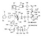
次に、図3を参照しつつOCTユニット150の構成について説明する。同図に示すOCTユニット150は、従来の光画像計測装置とほぼ同様の光学系を有するものであり、光源から出力された光を参照光と信号光とに分割し、参照物体を経由した参照光と被測定物体(眼底Ef)を経由した信号光とを重畳して干渉光を生成する干渉計を具備するとともに、この干渉光の検出結果を解析して被測定物体(眼底Ef)の画像を形成するように構成されている。[Configuration of OCT unit]
Next, the configuration of the
低コヒーレンス光源160は、低コヒーレンス光L0を出力するスーパールミネセントダイオード(SLD)や発光ダイオード(LED)等の広帯域光源により構成されている。この低コヒーレンス光L0は、たとえば、近赤外領域の波長を有し、かつ、数十マイクロメートル程度の時間的コヒーレンス長を有する光とされる。この低コヒーレンス光源160から出力される低コヒーレンス光L0は、眼底カメラユニット1Aの照明光(波長約400nm〜800nm)よりも長い波長、たとえば約800nm〜900nmの範囲に含まれる波長を有している。この低コヒーレンス光源160は、本発明の「光源」の一例に相当するものである。 The low coherence
低コヒーレンス光源160から出力された低コヒーレンス光L0は、たとえばシングルモードファイバないしはPMファイバ(Polarization maintaining fiber;偏波面保持ファイバ)からなる光ファイバ161を通じて光カプラ(coupler)162に導かれる。光カプラ162は、この低コヒーレンス光L0を参照光LRと信号光LSとに分割する。 The low coherence light L0 output from the low coherence
なお、光カプラ162は、光を分割する手段(スプリッタ;splitter)、及び、光を重畳する手段(カプラ)の双方の作用を有するが、ここでは慣用的に「光カプラ」と称することにする。 The
光カプラ162により生成された参照光LRは、シングルモードファイバ等からなる光ファイバ163により導光されてファイバ端面から出射される。出射された参照光LRは、コリメータレンズ171により平行光束とされた後、ガラスブロック172及び濃度フィルタ173を経由し、参照ミラー174(参照物体)によって反射される。 The reference light LR generated by the
参照ミラー174により反射された参照光LRは、再び濃度フィルタ173及びガラスブロック172を経由し、コリメータレンズ171によって光ファイバ163のファイバ端面に集光される。集光された参照光LRは、光ファイバ163を通じて光カプラ162に導かれる。 The reference light LR reflected by the
なお、ガラスブロック172と濃度フィルタ173は、参照光LRと信号光LSの光路長(光学距離)を合わせるための遅延手段として、また参照光LRと信号光LSの分散特性を合わせるための手段として作用している。 The
また、参照ミラー174は、参照光LRの進行方向に沿って移動可能に構成されている。それにより、被検眼Eの眼軸長などに応じた参照光LRの光路長を確保するようになっている。なお、参照ミラー174の移動は、モータ等の駆動装置を含む駆動機構によって行われる。 The
一方、光カプラ162により生成された信号光LSは、シングルモードファイバ等からなる光ファイバ164により接続線152の端部まで導光される。接続線152の内部には光ファイバ152aが導通されている。ここで、光ファイバ164と光ファイバ152aとは、単一の光ファイバにより構成されていてもよいし、また、各々の端面同士を接合して一体形成されたものであってもよい。いずれにしても、光ファイバ164、152aは、眼底カメラユニット1AとOCTユニット150との間で、信号光LSを伝送可能に構成されていれば十分である。 On the other hand, the signal light LS generated by the
信号光LSは、接続線152内部を導光されて眼底カメラユニット1Aに案内される。そして、レンズ142、走査ユニット141、ダイクロイックミラー134、撮影レンズ126、リレーレンズ125、変倍レンズ124、撮影絞り121、孔開きミラー112の孔部112a、対物レンズ113を経由して、被検眼Eに入射する(このとき、バリアフィルタ122、123は、それぞれ光路から退避されている。)。 The signal light LS is guided through the
被検眼Eに入射した信号光LSは、眼底(網膜)Ef上にて結像し反射される。このとき、信号光LSは、眼底Efの表面で反射されるだけでなく、眼底Efの深部領域にも到達して屈折率境界において散乱される。したがって、眼底Efを経由した信号光LSは、眼底Efの表面形態を反映する情報と、眼底深部組織の屈折率境界における後方散乱の状態を反映する情報とを含んだ光となる。この光を単に「信号光LSの眼底反射光」と呼ぶことがある。 The signal light LS incident on the eye E is imaged and reflected on the fundus (retina) Ef. At this time, the signal light LS is not only reflected by the surface of the fundus oculi Ef, but also reaches the deep region of the fundus oculi Ef and is scattered at the refractive index boundary. Therefore, the signal light LS passing through the fundus oculi Ef is light including information reflecting the surface morphology of the fundus oculi Ef and information reflecting the state of backscattering at the refractive index boundary of the deep fundus tissue. This light may be simply referred to as “fundus reflected light of the signal light LS”.
信号光LSの眼底反射光は、上記経路を逆向きに進行して光ファイバ152aの端面152bに集光され、この光ファイバ152を通じてOCTユニット150に入射し、光ファイバ164を通じて光カプラ162に戻ってくる。光カプラ162は、この信号光LSと、参照ミラー174にて反射された参照光LRとを重畳して干渉光LCを生成する。生成された干渉光LCは、シングルモードファイバ等からなる光ファイバ165を通じてスペクトロメータ180に導光される。 The fundus reflection light of the signal light LS travels in the reverse direction in the above path, is condensed on the
ここで、本発明の「干渉光生成手段」は、少なくとも、光カプラ162、光ファイバ163、164、参照ミラー174を含む干渉計によって構成される。なお、本実施形態ではマイケルソン型の干渉計を採用したが、たとえばマッハツェンダー型など任意のタイプの干渉計を適宜採用することが可能である。 Here, the “interference light generating means” of the present invention is configured by an interferometer including at least an
スペクトロメータ(分光計)180は、コリメータレンズ181、回折格子182、結像レンズ183、CCD184を含んで構成される。本実施形態の回折格子182は、透過型回折格子であるが、もちろん反射型回折格子を用いることも可能である。また、CCD184に代えて、その他の光検出素子を適用することももちろん可能である。このような光検出素子は、本発明の「第2の検出手段」の一例に相当するものである。 The spectrometer (spectrometer) 180 includes a
スペクトロメータ180に入射した干渉光LCは、コリメータレンズ181により平行光束とされた後、回折格子182によって分光(スペクトル分解)される。分光された干渉光LCは、結像レンズ183によってCCD184の撮像面上に結像される。CCD184は、この干渉光LCを受光して電気的な検出信号に変換し、この検出信号を演算制御装置200に出力する。 The interference light LC incident on the
〔演算制御装置の構成〕
次に、演算制御装置200の構成について説明する。この演算制御装置200は、OCTユニット150のスペクトロメータ180のCCD184から入力される検出信号を解析して、被検眼Eの眼底Efの断層画像を形成する処理を行う。このときの解析手法は、従来のフーリエドメインOCTの手法と同じである。[Configuration of arithmetic control unit]
Next, the configuration of the arithmetic and
また、演算制御装置200は、眼底カメラユニット1Aの撮像装置10、12から出力される映像信号に基づいて眼底Efの表面(網膜)の形態を示す2次元画像を形成する処理を行う。 In addition, the arithmetic and
更に、演算制御装置200は、眼底カメラユニット1Aの各部の制御、及び、OCTユニット150の各部の制御を実行する。 Furthermore, the arithmetic and
眼底カメラユニット1Aの制御としては、たとえば、観察光源101や撮影光源103による照明光の出力制御、エキサイタフィルタ105、106やバリアフィルタ122、123の光路上への挿入/退避動作の制御、LCD139等の表示動作の制御、照明絞り110の移動制御(絞り値の制御)、撮影絞り121の絞り値の制御、変倍レンズ124の移動制御(倍率の制御)などを行う。また、演算制御装置200は、走査ユニット141内のガルバノミラー141A、141Bの回動動作の制御を行う。 Control of the
一方、OCTユニット150の制御としては、低コヒーレンス光源160による低コヒーレンス光の出力制御、参照ミラー174の移動制御、CCD184の蓄積時間の制御などを行う。 On the other hand, as control of the
以上のように作用する演算制御装置200のハードウェア構成の一例について、図4を参照しつつ説明する。演算制御装置200は、従来のコンピュータと同様のハードウェア構成を備えている。具体的には、マイクロプロセッサ201(CPU、MPU等)、RAM202、ROM203、ハードディスクドライブ(HDD)204、キーボード205、マウス206、ディスプレイ207、画像形成ボード208及び通信インターフェイス(I/F)209を含んで構成されている。これら各部は、バス200aを介して接続されている。 An example of the hardware configuration of the arithmetic and
マイクロプロセッサ201は、ハードディスクドライブ204に格納された制御プログラム204aをRAM202上に展開することにより、本実施形態に特徴的な動作を実行する。 The
また、マイクロプロセッサ201は、前述した装置各部の制御や、各種の演算処理などを実行する。また、キーボード205やマウス206からの操作信号に対応する装置各部の制御、ディスプレイ207による表示処理の制御、通信インターフェイス209による各種のデータや制御信号等の送受信処理の制御などを実行する。 Further, the
キーボード205、マウス206及びディスプレイ207は、眼底観察装置1のユーザインターフェイスとして使用される。キーボード205は、たとえば文字や数字等をタイピング入力するためのデバイスとして用いられる。マウス206は、ディスプレイ207の表示画面に対する各種入力操作を行うためのデバイスとして用いられる。 The
また、ディスプレイ207は、LCDやCRT(Cathode Ray Tube)等の任意の表示デバイスであり、眼底観察装置1により形成された眼底Efの画像を表示したり、各種の操作画面や設定画面などを表示したりする。 The
なお、眼底観察装置1のユーザインターフェイスは、このような構成に限定されるものではなく、たとえばトラックボール、ジョイスティック、タッチパネル式のLCD、眼科検査用のコントロールパネルなど、各種情報を表示出力する機能と、各種情報を入力する機能とを具備する任意のユーザインターフェイス手段を用いて構成することが可能である。 Note that the user interface of the fundus
画像形成ボード208は、被検眼Eの眼底Efの画像を形成する処理を行う専用の電子回路である。この画像形成ボード208には、眼底画像形成ボード208aとOCT画像形成ボード208bとが設けられている。眼底画像形成ボード208aは、眼底カメラユニット1Aの撮像装置10や撮像装置12からの映像信号に基づいて眼底画像を形成するように動作する、専用の電子回路である。また、OCT画像形成ボード208bは、OCTユニット150のスペクトロメータ180のCCD184からの検出信号に基づいて眼底画像(断層画像)を形成するように動作する、専用の電子回路である。このような画像形成ボード208を設けることにより、眼底画像を形成する処理の処理速度を向上させることができる。 The image forming board 208 is a dedicated electronic circuit that performs processing for forming an image of the fundus oculi Ef of the eye E. The image forming board 208 is provided with a fundus
通信インターフェイス209は、マイクロプロセッサ201からの制御信号を、眼底カメラユニット1AやOCTユニット150に送信する処理を行う。また、通信インターフェイス209は、眼底カメラユニット1Aの撮像装置10、12からの映像信号や、OCTユニット150のCCD184からの検出信号を受信して、画像形成ボード208に入力する処理などを行う。このとき、通信インターフェイス209は、撮像装置10、12からの映像信号を眼底画像形成ボード208aに入力し、CCD184からの検出信号をOCT画像形成ボード208bに入力するように動作する。 The
また、演算制御装置200がLAN(Local Area Network)やインターネット等のネットワークに接続されている場合には、通信インターフェイス209に、LANカード等のネットワークアダプタやモデム等の通信機器を具備させて、当該ネットワーク経由のデータ通信を行えるように構成することが可能である。その場合、制御プログラム204aを格納するサーバを設置するとともに、演算制御装置200を当該サーバのクライアント端末として構成することができる。 When the arithmetic and
〔制御系の構成〕
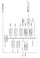
以上のような構成を有する眼底観察装置1の制御系の構成について、図5を参照しつつ説明する。図5は、眼底観察装置1が具備する構成のうち、本発明に係る動作や処理に関わる部分を特に選択して示したものである。[Control system configuration]
The configuration of the control system of the fundus
眼底観察装置1の制御系は、演算制御装置200の制御部210を中心に構成される。制御部210は、マイクロプロセッサ201、RAM202、ROM203、ハードディスクドライブ204(制御プログラム204a)、通信インターフェイス209等を含んで構成される。 The control system of the fundus
制御部210は、制御プログラム204aに基づいて動作するマイクロプロセッサ201により、前述の制御処理を実行する。特に、眼底カメラユニット1Aのミラー駆動機構241、242をそれぞれ制御することにより、ガルバノミラー141A、141Bをそれぞれ独立に動作させるようになっている。 The
また、制御部210は、眼底観察装置1により撮影される2種類の画像、すなわち眼底カメラユニット1Aによる眼底Efの表面の2次元画像(眼底画像Ef′)と、OCTユニット150により得られた検出信号を基に形成される眼底Efの画像とを、ユーザインターフェイス240のディスプレイ207に表示させるための制御を行う。これらの眼底画像は、それぞれ別々にディスプレイ207にさせることもできるし、それらを並べて同時に表示させることもできる。 The
画像形成部220は、眼底カメラユニット1Aの撮像装置10、12からの映像信号に基づいて眼底画像を形成する処理と、OCTユニット150のCCD184からの検出信号に基づいて眼底画像を形成する処理とを行うもので、画像形成ボード208を含んで構成される。 The
画像処理部230は、画像形成部220により形成された眼底画像に対して各種の画像処理を施すものである。たとえば、OCTユニット150からの検出信号に基づく眼底Efの断層画像に基づいて眼底Efの3次元画像を形成する処理や、眼底画像の輝度調整等の各種補正処理などを実行するものである。 The
ユーザインターフェイス(UI)240は、キーボード205やマウス206等の操作デバイスと、ディスプレイ207等の表示デバイスとを具備している。 The user interface (UI) 240 includes operation devices such as a
以下、制御部210による信号光LSの走査の制御態様について、そして画像形成部220及び画像処理部230によるOCTユニット150からの検出信号に対する処理の態様について、それぞれ説明する。なお、眼底カメラユニット1Aからの映像信号に対する画像形成部220等の処理については、従来と同様であるので説明は省略することにする。 Hereinafter, the control mode of scanning of the signal light LS by the
〔信号光の走査について〕
信号光LSの走査は、前述のように、眼底カメラユニット1Aの走査ユニット141のガルバノミラー141A、141Bの反射面の向きを変更することにより行われる。制御部210は、ミラー駆動機構241、242をそれぞれ制御することで、ガルバノミラー141A、141Bの反射面の向きをそれぞれ変更し、信号光LSを眼底Ef上において走査する。[Scanning signal light]
As described above, the scanning of the signal light LS is performed by changing the direction of the reflecting surfaces of the galvanometer mirrors 141A and 141B of the
ガルバノミラー141Aの反射面の向きが変更されると、信号光LSは、眼底Ef上において水平方向(図1のx方向)に走査される。一方、ガルバノミラー141Aの反射面の向きが変更されると、信号光LSは、眼底Ef上において垂直方向(図1のy方向)に走査される。また、ガルバノミラー141A、141Bの双方の反射面の向きを同時に変更させることにより、x方向とy方向とを合成した方向に信号光LSを走査することができる。すなわち、これら2つのガルバノミラー141A、141Bを制御することにより、xy平面上の任意の方向に信号光LSを走査することができる。 When the direction of the reflecting surface of the
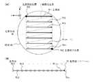
図6は、眼底Efの画像を形成するための信号光LSの走査態様の一例を表している。図6(A)は、信号光LSが被検眼Eに入射する方向から眼底Efを見た(つまり図1の−z方向から+z方向を見た)ときの、信号光LSの走査態様の一例を表す。また、図6(B)は、眼底Ef上の各走査線における走査点(画像計測を行う位置)の配列態様の一例を表す。 FIG. 6 illustrates an example of a scanning mode of the signal light LS for forming an image of the fundus oculi Ef. FIG. 6A shows an example of a scanning mode of the signal light LS when the fundus oculi Ef is viewed from the direction in which the signal light LS is incident on the eye E (that is, when viewed from the −z direction to the + z direction in FIG. 1). Represents. FIG. 6B illustrates an example of an arrangement mode of scanning points (positions where image measurement is performed) on each scanning line on the fundus oculi Ef.
図6(A)に示すように、信号光LSは、あらかじめ設定された矩形の走査領域R内を走査される。この走査領域R内には、x方向に複数(m本)の走査線R1〜Rmが設定されている。各走査線Ri(i=1〜m)に沿って信号光LSが走査されるときに、干渉光LCの検出信号が生成されるようになっている。 As shown in FIG. 6A, the signal light LS is scanned in a rectangular scanning region R set in advance. In this scanning region R, a plurality (m) of scanning lines R1 to Rm are set in the x direction. When the signal light LS is scanned along each scanning line Ri (i = 1 to m), a detection signal of the interference light LC is generated.
ここで、各走査線Riの方向を「主走査方向」と呼び、それに直交する方向を「副走査方向」と呼ぶことにする。したがって、信号光LSの主走査方向への走査は、ガルバノミラー141Aの反射面の向きを変更することにより実行され、副走査方向への走査は、ガルバノミラー141Bの反射面の向きを変更することによって実行される。 Here, the direction of each scanning line Ri is referred to as a “main scanning direction”, and a direction orthogonal to the direction is referred to as a “sub-scanning direction”. Therefore, scanning in the main scanning direction of the signal light LS is executed by changing the direction of the reflecting surface of the
各走査線Ri上には、図6(B)に示すように、複数(n個)の走査点Ri1〜Rinがあらかじめ設定されている。 On each scanning line Ri, as shown in FIG. 6B, a plurality (n) of scanning points Ri1 to Rin are set in advance.
図6に示す走査を実行するために、制御部210は、まず、ガルバノミラー141A、141Bを制御し、眼底Efに対する信号光LSの入射目標を第1の走査線R1上の走査開始位置RS(走査点R11)に設定する。続いて、制御部210は、低コヒーレンス光源2を制御し、低コヒーレンス光L0をフラッシュ発光させて、走査開始位置RSに信号光LSを入射させる。CCD184は、この信号光LSの走査開始位置RSにおける眼底反射光に基づく干渉光LCを受光し、検出信号を制御部210に出力する。 In order to execute the scan illustrated in FIG. 6, the
次に、制御部210は、ガルバノミラー141Aを制御して、信号光LSを主走査方向に走査して、その入射目標を走査点R12に設定し、低コヒーレンス光L0をフラッシュ発光させて走査点R12に信号光LSを入射させる。CCD184は、この信号光LSの走査点R12における眼底反射光に基づく干渉光LCを受光し、検出信号を制御部210に出力する。 Next, the
制御部210は、同様にして、信号光LSの入射目標を走査点R13、R14、・・・、R1(n−1)、R1nと順次移動させつつ、各走査点において低コヒーレンス光L0をフラッシュ発光させることにより、各走査点ごとの干渉光LCに対応してCCD184から出力される検出信号を取得する。 Similarly, the
第1の走査線R1の最後の走査点R1nにおける計測が終了したら、制御部210は、ガルバノミラー141A、141Bを同時に制御して、信号光LSの入射目標を、線換え走査rに沿って第2の走査線R2の最初の走査点R21まで移動させる。そして、この第2の走査線R2の各走査点R2j(j=1〜n)について前述の計測を行うことで、各走査点R2jに対応する検出信号をそれぞれ取得する。 When the measurement at the last scanning point R1n of the first scanning line R1 is completed, the
同様に、第3の走査線R3、・・・・、第m−1の走査線R(m−1)、第mの走査線Rmのそれぞれについて計測を行い、各走査点に対応する検出信号を取得する。なお、走査線Rm上の符号REは、走査点Rmnに対応する走査終了位置である。 Similarly, measurement is performed for each of the third scanning line R3,..., The m−1th scanning line R (m−1), and the mth scanning line Rm, and a detection signal corresponding to each scanning point. To get. Note that the symbol RE on the scanning line Rm is a scanning end position corresponding to the scanning point Rmn.
それにより、制御部210は、走査領域R内のm×n個の走査点Rij(i=1〜m、j=1〜n)に対応するm×n個の検出信号を取得する。以下、走査点Rijに対応する検出信号をDijと表すことがある。 Thereby, the
以上のような走査点の移動と低コヒーレンス光L0の出力との連動制御は、たとえば、ミラー駆動機構241、242に対する制御信号の送信タイミングと、低コヒーレンス光源2に対する制御信号(出力要求信号)の送信タイミングとを互いに同期させることによって実現することができる。 The linked control of the scanning point movement and the output of the low-coherence light L0 as described above is performed, for example, by transmitting a control signal to the
制御部210は、上述のように各ガルバノミラー141A、141Bを動作させるときに、その動作内容を示す情報として各走査線Riの位置や各走査点Rijの位置(xy座標系における座標)を記憶しておくようになっている。この記憶内容(走査位置情報)は、従来と同様に画像形成処理において用いられる。 When the galvanometer mirrors 141A and 141B are operated as described above, the
〔画像処理について〕
次に、画像形成部220及び画像処理部230によるOCT画像に関する処理について、その一例を説明する。[About image processing]
Next, an example of processing related to an OCT image by the
画像形成部220は、各走査線Ri(主走査方向)に沿った眼底Efの断層画像の形成処理を実行する。また、画像処理部230は、画像形成部220により形成された断層画像に基づく眼底Efの3次元画像の形成処理などを実行する。 The
画像形成部220による断層画像の形成処理は、従来と同様に、2段階の演算処理を含んで構成される。第1段階の演算処理においては、各走査点Rijに対応する検出信号Dijに基づいて、その走査点Rijにおける眼底Efの深度方向(図1に示すz方向)の画像を形成する。 The tomographic image forming process by the
図7は、画像形成部220により形成される断層画像の態様を表している。第2段階の演算処理においては、各走査線Riについて、その上のn個の走査点Ri1〜Rinにおける深度方向の画像に基づき、この走査線Riに沿った眼底Efの断層画像Giを形成する。このとき、画像形成部220は、各走査点Ri1〜Rinの位置情報(前述の走査位置情報)を参照して各走査点Ri1〜Rinの配列及び間隔を決定して、この走査線Riを形成するようになっている。以上の処理により、副走査方向(y方向)の異なる位置におけるm個の断層画像G1〜Gmが得られる。 FIG. 7 shows an aspect of a tomographic image formed by the
次に、画像処理部230による眼底Efの3次元画像の形成処理について説明する。眼底Efの3次元画像は、上記の演算処理により得られたm個の断層画像に基づいて形成される。画像処理部230は、隣接する断層画像Gi、G(i+1)の間の画像を補間する公知の補間処理を行うなどして、眼底Efの3次元画像を形成する。 Next, a process for forming a three-dimensional image of the fundus oculi Ef by the
このとき、画像処理部230は、各走査線Riの位置情報を参照して各走査線Riの配列及び間隔を決定して、この3次元画像を形成するようになっている。この3次元画像には、各走査点Rijの位置情報(前述の走査位置情報)と、深度方向の画像におけるz座標とに基づいて、3次元座標系(x、y、z)が設定される。 At this time, the
また、画像処理部230は、この3次元画像に基づいて、主走査方向(x方向)以外の任意方向の断面における眼底Efの断層画像を形成することができる。断面が指定されると、画像処理部230は、この指定断面上の各走査点(及び/又は補間された深度方向の画像)の位置を特定し、各特定位置における深度方向の画像(及び/又は補間された深度方向の画像)を3次元画像から抽出し、抽出された複数の深度方向の画像を配列させることにより当該指定断面における眼底Efの断層画像を形成する。 Further, the
なお、図7に示す画像Gmjは、走査線Rm上の走査点Rmjにおける深度方向(z方向)の画像を表している。同様に、前述の第1段階の演算処理において形成される、各走査線Ri上の各走査点Rijにおける深度方向の画像を、「画像Gij」と表す。 Note that an image Gmj shown in FIG. 7 represents an image in the depth direction (z direction) at the scanning point Rmj on the scanning line Rm. Similarly, an image in the depth direction at each scanning point Rij on each scanning line Ri, which is formed in the above-described first stage arithmetic processing, is represented as “image Gij”.
[作用・効果]
以上のような構成を有する本実施形態に係る眼底観察装置1の作用及び効果について説明する。[Action / Effect]
The operation and effect of the fundus
この眼底観察装置1は、眼底Efの表面の状態を表す2次元画像を得るための眼底カメラとして作用する眼底カメラユニット1Aと、眼底Efの断層画像(及び3次元画像)を得るための光画像計測装置として作用するOCTユニット150とを備えている。 The fundus
OCTユニット150による画像形成に使用される信号光の光路は、眼底カメラユニット1Aの撮影光学系130により形成される光路(撮影光路)に合成されて被検眼Eに導かれる。この光路の合成は、ダイクロイックミラー134によって為される。 The optical path of the signal light used for image formation by the
また、信号光LSの眼底反射光は、撮影光路に沿ってダイクロイックミラー134まで導光されるとともに、このダイクロイックミラー134によって撮影光路から分離されてOCTユニット150に向かうようになっている。 Further, the fundus reflection light of the signal light LS is guided to the
このように、眼底カメラユニット1Aの撮影光路と、信号光LSの光路とを合成し、分離するように作用するダイクロイックミラー134(光路分離合成手段)を設けることにより、眼底Efの表面の2次元画像と眼底Efの断層画像(及び3次元画像)との双方を取得することが可能となる。 In this way, by providing the dichroic mirror 134 (optical path separation / synthesis means) that combines and separates the imaging optical path of the
特に、被検眼Eに対して、眼底カメラユニット1Aによる照明光の照射と、OCTユニット150による信号光LSの照射とを同時に行っても、それぞれの眼底反射光をダイクロイックミラー134によって分離し、それぞれを検出して画像を形成することができるので、眼底Efの表面の2次元画像と眼底Efの断層画像の双方を同時に撮影することが可能である。 In particular, even if irradiation of illumination light by the
このとき、OCTユニット150からの信号光LSと同時に照射される照明光は、撮影光源103からの近赤外光であってもよいし、観察光源101からの可視光であってもよい。 At this time, the illumination light irradiated simultaneously with the signal light LS from the
[変形例]
以上に詳述した構成は、本発明に係る眼底観察装置を好適に実施するための一例に過ぎないものである。したがって、本発明の要旨の範囲内における任意の変形を適宜に施すことが可能である。[Modification]
The configuration described in detail above is merely an example for favorably implementing the fundus oculi observation device according to the present invention. Therefore, arbitrary modifications within the scope of the present invention can be appropriately made.
たとえば、上記の実施形態では、低コヒーレンス光L0として、約800nm〜900nmの波長の近赤外光を使用しているが、眼底Efのより深い領域の画像計測を行うために、より長い波長の光を使用することができる。たとえば、約900nm〜1000nmの波長の近赤外光を使用したり、約1000nm〜1100nmの波長の近赤外光を使用したりすることができる。 For example, in the above embodiment, near-infrared light having a wavelength of about 800 nm to 900 nm is used as the low coherence light L0. Light can be used. For example, near infrared light having a wavelength of about 900 nm to 1000 nm can be used, or near infrared light having a wavelength of about 1000 nm to 1100 nm can be used.
なお、約900nm〜1000nmの波長の低コヒーレンス光L0を使用する場合には、眼底カメラユニット1Aにおける照明光として、たとえば約700nm〜900nmの波長の近赤外光を使用することができる。また、約1000nm〜1100nmの波長の近赤外光を低コヒーレンス光L0を使用する場合には、眼底カメラユニット1Aにおける照明光として、たとえば約850nm〜1000nmの波長の近赤外光を使用することができる。ここで、いずれの場合においても、低コヒーレンス光L0の波長を、眼底カメラユニット1Aの照明光の波長よりも長く設定することが望ましいが、波長の長短の関係を逆にした構成を適用することも可能である。 When using low coherence light L0 having a wavelength of about 900 nm to 1000 nm, near infrared light having a wavelength of about 700 nm to 900 nm, for example, can be used as illumination light in the
また、本発明に係る眼底観察装置の第1の画像形成手段は、眼底カメラ(ユニット)に限定されるものではなく、眼底表面の2次元画像の形成することが可能な任意の眼科装置を適用することが可能である。たとえば、スリットランプ(細隙灯顕微鏡装置)などを第1の画像形成手段として用いることができる。 The first image forming means of the fundus oculi observation device according to the present invention is not limited to the fundus camera (unit), and any ophthalmologic apparatus capable of forming a two-dimensional image of the fundus oculi surface is applied. Is possible. For example, a slit lamp (slit lamp microscope apparatus) or the like can be used as the first image forming means.
また、上記の実施形態では、画像形成部220(画像形成ボード208)によって眼底画像の形成処理を行うとともに、制御部210(マイクロプロセッサ201等)によって各種制御処理を行うようになっているが、これら双方の処理を1台若しくは複数台のコンピュータによって行うように構成することができる。 In the above embodiment, the fundus image is formed by the image forming unit 220 (the image forming board 208) and various control processes are performed by the control unit 210 (the
1 眼底観察装置
1A 眼底カメラユニット
8c 装着部
10、12 撮像装置
100 照明光学系
101 観察光源
103 撮影光源
120 撮影光学系
134、136 ダイクロイックミラー
141 走査ユニット
141A、141B ガルバノミラー
142 レンズ
150 OCTユニット
151 コネクタ部
152 接続線
152a、161、163、164、165 光ファイバ
160 低コヒーレンス光源
162 光カプラ
174 参照ミラー
180 スペクトロメータ
184 CCD
200 演算制御装置
201 マイクロプロセッサ
208 画像形成ボード
208a 眼底画像形成ボード
208b OCT画像形成ボード
210 制御部
220 画像形成部
230 画像処理部
240 ユーザインターフェイス
241、242 ミラー駆動機構
L0 低コヒーレンス光
LR 参照光
LS 信号光
LC 干渉光
R 走査領域
R1〜Rm 走査線
Rij(i=1〜m、j=1〜n) 走査点
G1〜Gm 断層画像
Gij(i=1〜m、j=1〜n) 深度方向の画像
E 被検眼
Ef 眼底
Ef′ 眼底画像(2次元画像)DESCRIPTION OF
200
Claims (8)
Translated fromJapanese前記照明光とは異なる波長の光を出力する光源と、該光源から出力された前記光を前記眼底に向かう信号光と参照物体に向かう参照光とに分割し、前記眼底を経由した信号光と前記参照物体を経由した参照光とを重畳させて干渉光を生成する干渉光生成手段と、該生成された干渉光を検出する第2の検出手段とを有し、該第2の検出手段による検出結果に基づいて前記眼底の断層画像を形成する第2の画像形成手段と、
前記撮影光学系により形成される撮影光路と前記眼底に向かう信号光の光路とを合成するとともに、前記撮影光路と前記眼底を経由した信号光の光路とを分離する光路合成分離手段と、
を備え、
前記撮影光路に前記合成された前記信号光は、前記撮影光路を介して前記眼底に照射され、
前記撮影光路から前記分離された前記信号光は、前記干渉光生成手段により前記参照光と前記重畳される、
ことを特徴とする眼底観察装置。An illumination optical system that irradiates illumination light to the fundus of the eye to be examined and an imaging optical system that detects illumination light passing through the fundus by a first detection unit, based on a detection result by the first detection unit First image forming means for forming a two-dimensional image of the fundus surface;
A light source that outputs light having a wavelength different from that of the illumination light; and the light output from the light source is divided into signal light that travels toward the fundus and reference light that travels toward a reference object, and signal light that passes through the fundus An interference light generation unit that generates interference light by superimposing the reference light that has passed through the reference object; and a second detection unit that detects the generated interference light. A second image forming means for forming a tomographic image of the fundus based on a detection result;
An optical path combining / separating unit that combines the imaging optical path formed by the imaging optical system and the optical path of the signal light toward the fundus and separates the imaging optical path and the optical path of the signal light passing through the fundus;
With
The combined signal light in the imaging optical path is irradiated to the fundus through the imaging optical path,
The signal light separated from the imaging optical path is superimposed on the reference light by the interference light generation means,
A fundus oculi observation device characterized by that.
ことを特徴とする請求項1に記載の眼底観察装置。The illumination light of the first image forming unit and the light output by the light source of the second image forming unit are each light having a wavelength in the near infrared region.
The fundus oculi observation device according to claim 1.
ことを特徴とする請求項2に記載の眼底観察装置。The light output by the light source has a longer wavelength than the illumination light.
The fundus oculi observation device according to claim 2.
前記光源により出力される光は800nm〜900nmの範囲に含まれる波長を有する、
ことを特徴とする請求項3に記載の眼底観察装置。The illumination light has a wavelength included in a range of 700 nm to 800 nm,
The light output by the light source has a wavelength included in the range of 800 nm to 900 nm.
The fundus oculi observation device according to claim 3.
前記光源により出力される光は1000nm〜1100nmの範囲に含まれる波長を有する、
ことを特徴とする請求項3に記載の眼底観察装置。The illumination light has a wavelength included in the range of 850 nm to 1000 nm,
The light output by the light source has a wavelength included in the range of 1000 nm to 1100 nm.
The fundus oculi observation device according to claim 3.
ことを特徴とする請求項1〜請求項5のいずれか一項に記載の眼底観察装置。The optical path combining / separating means is a dichroic mirror.
The fundus oculi observation device according to any one of claims 1 to 5, wherein:
前記撮影光学系は、前記眼底を経由した前記可視領域の波長を有する照明光を検出する第3の検出手段を更に備え、
前記第1の画像形成手段は、前記第3の検出手段による検出結果に基づいて前記眼底の表面の2次元画像を形成する、
ことを特徴とする請求項2〜請求項6のいずれか一項に記載の眼底観察装置。The illumination optical system of the first image forming unit further includes a visible light source that outputs illumination light having a wavelength in the visible region,
The photographing optical system further includes third detection means for detecting illumination light having a wavelength in the visible region via the fundus.
The first image forming unit forms a two-dimensional image of the surface of the fundus based on a detection result by the third detection unit;
The fundus oculi observation device according to any one of claims 2 to 6, wherein
ことを特徴とする請求項7に記載の眼底観察装置。The photographing optical system further includes optical path separation means for separating an optical path of illumination light having a wavelength in the infrared region and an optical path of illumination light having a wavelength in the visible region.
The fundus oculi observation device according to claim 7.
Priority Applications (4)
| Application Number | Priority Date | Filing Date | Title |
|---|---|---|---|
| JP2006003065AJP2007181631A (en) | 2006-01-10 | 2006-01-10 | Fundus observation device |
| CN2007100009241ACN100998495B (en) | 2006-01-10 | 2007-01-08 | Fundus observation device |
| EP07000291AEP1806092A1 (en) | 2006-01-10 | 2007-01-08 | A fundus observation device |
| US11/621,676US7784941B2 (en) | 2006-01-10 | 2007-01-10 | Fundus observation device |
Applications Claiming Priority (1)
| Application Number | Priority Date | Filing Date | Title |
|---|---|---|---|
| JP2006003065AJP2007181631A (en) | 2006-01-10 | 2006-01-10 | Fundus observation device |
Related Child Applications (1)
| Application Number | Title | Priority Date | Filing Date |
|---|---|---|---|
| JP2012233479ADivisionJP5209143B2 (en) | 2012-10-23 | 2012-10-23 | Fundus observation device |
Publications (1)
| Publication Number | Publication Date |
|---|---|
| JP2007181631Atrue JP2007181631A (en) | 2007-07-19 |
Family
ID=38257373
Family Applications (1)
| Application Number | Title | Priority Date | Filing Date |
|---|---|---|---|
| JP2006003065APendingJP2007181631A (en) | 2006-01-10 | 2006-01-10 | Fundus observation device |
Country Status (2)
| Country | Link |
|---|---|
| JP (1) | JP2007181631A (en) |
| CN (1) | CN100998495B (en) |
Cited By (11)
| Publication number | Priority date | Publication date | Assignee | Title |
|---|---|---|---|---|
| JP2007252693A (en)* | 2006-03-24 | 2007-10-04 | Topcon Corp | Fundus observation device |
| EP2179688A1 (en) | 2008-10-24 | 2010-04-28 | Canon Kabushiki Kaisha | Connection adapter, optical tomographic imaging apparatus, program for executing imaging method and memory device for the program |
| JP2011500188A (en)* | 2007-10-19 | 2011-01-06 | オプトメッド オサケ ユキチュア | Organ lighting |
| JP2011510720A (en)* | 2008-02-01 | 2011-04-07 | リノス フォトニクス ゲゼルシャフト ミット ベシュレンクテル ハフツング ウンド ツェーオー,カーゲー | Integrated fundus scanning device for OCT and fundus imaging |
| US20110292341A1 (en)* | 2010-06-01 | 2011-12-01 | Seema Somani | Method and apparatus for enhanced eye measurement |
| JP2013208394A (en)* | 2012-03-30 | 2013-10-10 | Canon Inc | Optical coherence tomographic imaging apparatus and method thereof |
| US9131840B2 (en) | 2009-05-22 | 2015-09-15 | Canon Kabushiki Kaisha | Optical coherence tomographic imaging apparatus and tomographic imaging method |
| EP2926720A2 (en) | 2014-03-31 | 2015-10-07 | Nidek co., Ltd. | Fundus Photography Device |
| JP2015531275A (en)* | 2012-09-28 | 2015-11-02 | カール ツアイス メディテック アクチエンゲゼルシャフト | Method for realizing OCT imaging and other imaging of the eye |
| JP2017159089A (en)* | 2017-05-10 | 2017-09-14 | キヤノン株式会社 | Fundus imaging apparatus |
| CN114668583A (en)* | 2022-05-30 | 2022-06-28 | 季华实验室 | An ophthalmic laser surgery treatment system |
Families Citing this family (11)
| Publication number | Priority date | Publication date | Assignee | Title |
|---|---|---|---|---|
| CN102525404B (en)* | 2010-11-05 | 2015-09-30 | 尼德克株式会社 | Ophthalmoligic instrument |
| CN102389290B (en)* | 2011-08-01 | 2013-07-03 | 温州医学院眼视光研究院 | Frequency-domain optical coherence tomography system |
| CN105011900B (en)* | 2014-04-30 | 2018-02-02 | 卡尔蔡司医疗技术公司 | Method and apparatus for generating wide visual field optical coherence body tomographic map |
| WO2018136518A1 (en)* | 2017-01-17 | 2018-07-26 | Duke University | Optical coherence tomography device and system |
| WO2020111323A1 (en)* | 2018-11-29 | 2020-06-04 | 한국광기술원 | Ophthalmological composite optical imaging apparatus and control method therefor |
| CN109691977B (en)* | 2018-12-29 | 2023-11-28 | 佛山科学技术学院 | Non-confocal adaptive optics imaging system |
| CN111166283A (en)* | 2019-12-24 | 2020-05-19 | 深圳盛达同泽科技有限公司 | Fundus shooting system |
| CN111820866B (en)* | 2020-07-31 | 2023-07-18 | 嘉兴中润光学科技股份有限公司 | Fundus illumination system |
| CN113229777B (en)* | 2021-04-07 | 2022-09-23 | 上海美沃精密仪器股份有限公司 | Visual quality analyzer |
| CN113509142B (en)* | 2021-06-07 | 2023-06-02 | 天津市索维电子技术有限公司 | Large-vision retina examination device |
| CN119969953A (en)* | 2025-02-21 | 2025-05-13 | 河南省科学院物理研究所 | Color 3D fundus imager optical system |
Citations (6)
| Publication number | Priority date | Publication date | Assignee | Title |
|---|---|---|---|---|
| JPS5352650A (en)* | 1976-10-22 | 1978-05-13 | Sentoraru Kousan Kk | Method of producing halff cooked frozen food from cuttlefish |
| JPS63237762A (en)* | 1987-03-24 | 1988-10-04 | Sanken Shoten:Kk | Squid trunk-packed kamaboko |
| JP3014852U (en)* | 1995-02-17 | 1995-08-22 | 株式会社ニチレイ | Squid processed food packed with dim sum ingredients |
| JPH0880176A (en)* | 1994-09-14 | 1996-03-26 | Ajinomoto Co Inc | Method for producing fish paste product and enzyme preparation |
| JP2003061622A (en)* | 2001-08-23 | 2003-03-04 | Sumiko Tachibana | Food produced by using squid and method for producing the same |
| JP2005065550A (en)* | 2003-08-22 | 2005-03-17 | Kureha Chem Ind Co Ltd | Method for producing fish-paste product and method for heat-treating processed food |
Family Cites Families (5)
| Publication number | Priority date | Publication date | Assignee | Title |
|---|---|---|---|---|
| US5537162A (en)* | 1993-12-17 | 1996-07-16 | Carl Zeiss, Inc. | Method and apparatus for optical coherence tomographic fundus imaging without vignetting |
| US5506634A (en)* | 1994-07-05 | 1996-04-09 | Carl Zeiss, Inc. | Fundus illumination apparatus formed from three, separated radiation path systems |
| WO2000064331A1 (en)* | 1999-04-27 | 2000-11-02 | Kabushiki Kaisha Topcon | Fundus camera |
| CN1139361C (en)* | 2001-11-16 | 2004-02-25 | 清华大学 | Measuring arm of an optical coherence tomography ophthalmic tester combined with a slit lamp |
| CA2390072C (en)* | 2002-06-28 | 2018-02-27 | Adrian Gh Podoleanu | Optical mapping apparatus with adjustable depth resolution and multiple functionality |
- 2006
- 2006-01-10JPJP2006003065Apatent/JP2007181631A/enactivePending
- 2007
- 2007-01-08CNCN2007100009241Apatent/CN100998495B/ennot_activeExpired - Fee Related
Patent Citations (6)
| Publication number | Priority date | Publication date | Assignee | Title |
|---|---|---|---|---|
| JPS5352650A (en)* | 1976-10-22 | 1978-05-13 | Sentoraru Kousan Kk | Method of producing halff cooked frozen food from cuttlefish |
| JPS63237762A (en)* | 1987-03-24 | 1988-10-04 | Sanken Shoten:Kk | Squid trunk-packed kamaboko |
| JPH0880176A (en)* | 1994-09-14 | 1996-03-26 | Ajinomoto Co Inc | Method for producing fish paste product and enzyme preparation |
| JP3014852U (en)* | 1995-02-17 | 1995-08-22 | 株式会社ニチレイ | Squid processed food packed with dim sum ingredients |
| JP2003061622A (en)* | 2001-08-23 | 2003-03-04 | Sumiko Tachibana | Food produced by using squid and method for producing the same |
| JP2005065550A (en)* | 2003-08-22 | 2005-03-17 | Kureha Chem Ind Co Ltd | Method for producing fish-paste product and method for heat-treating processed food |
Cited By (18)
| Publication number | Priority date | Publication date | Assignee | Title |
|---|---|---|---|---|
| JP2007252693A (en)* | 2006-03-24 | 2007-10-04 | Topcon Corp | Fundus observation device |
| JP2011500188A (en)* | 2007-10-19 | 2011-01-06 | オプトメッド オサケ ユキチュア | Organ lighting |
| JP2011510720A (en)* | 2008-02-01 | 2011-04-07 | リノス フォトニクス ゲゼルシャフト ミット ベシュレンクテル ハフツング ウンド ツェーオー,カーゲー | Integrated fundus scanning device for OCT and fundus imaging |
| US8308297B2 (en) | 2008-10-24 | 2012-11-13 | Canon Kabushiki Kaisha | Connection adapter, optical tomographic imaging apparatus, program for executing imaging method and memory device for the program |
| EP2179688A1 (en) | 2008-10-24 | 2010-04-28 | Canon Kabushiki Kaisha | Connection adapter, optical tomographic imaging apparatus, program for executing imaging method and memory device for the program |
| JP2010119836A (en)* | 2008-10-24 | 2010-06-03 | Canon Inc | Connection adapter, optical tomographic imaging apparatus, program for executing imaging method and memory device for the program |
| US9131840B2 (en) | 2009-05-22 | 2015-09-15 | Canon Kabushiki Kaisha | Optical coherence tomographic imaging apparatus and tomographic imaging method |
| US9339186B2 (en) | 2010-06-01 | 2016-05-17 | Optovue, Inc. | Method and apparatus for enhanced eye measurements |
| WO2011153275A1 (en)* | 2010-06-01 | 2011-12-08 | Optovue, Inc. | Method and apparatus for enhanced eye measurement |
| US20110292341A1 (en)* | 2010-06-01 | 2011-12-01 | Seema Somani | Method and apparatus for enhanced eye measurement |
| JP2013208394A (en)* | 2012-03-30 | 2013-10-10 | Canon Inc | Optical coherence tomographic imaging apparatus and method thereof |
| JP2015531275A (en)* | 2012-09-28 | 2015-11-02 | カール ツアイス メディテック アクチエンゲゼルシャフト | Method for realizing OCT imaging and other imaging of the eye |
| EP2926720A2 (en) | 2014-03-31 | 2015-10-07 | Nidek co., Ltd. | Fundus Photography Device |
| US9723978B2 (en) | 2014-03-31 | 2017-08-08 | Nidek Co., Ltd. | Fundus photography device |
| US10117573B2 (en) | 2014-03-31 | 2018-11-06 | Nidek Co., Ltd. | Fundus photography device |
| JP2017159089A (en)* | 2017-05-10 | 2017-09-14 | キヤノン株式会社 | Fundus imaging apparatus |
| CN114668583A (en)* | 2022-05-30 | 2022-06-28 | 季华实验室 | An ophthalmic laser surgery treatment system |
| CN114668583B (en)* | 2022-05-30 | 2022-09-20 | 季华实验室 | Ophthalmic laser surgery treatment system |
Also Published As
| Publication number | Publication date |
|---|---|
| CN100998495B (en) | 2012-01-25 |
| CN100998495A (en) | 2007-07-18 |
Similar Documents
| Publication | Publication Date | Title |
|---|---|---|
| JP4884777B2 (en) | Fundus observation device | |
| JP4890878B2 (en) | Fundus observation device | |
| JP5523658B2 (en) | Optical image measuring device | |
| JP4864515B2 (en) | Fundus observation device | |
| JP4823693B2 (en) | Optical image measuring device | |
| JP4869756B2 (en) | Fundus observation device | |
| JP5061380B2 (en) | Fundus observation apparatus, ophthalmologic image display apparatus, and program | |
| JP4864516B2 (en) | Ophthalmic equipment | |
| JP2007181631A (en) | Fundus observation device | |
| JP4916779B2 (en) | Fundus observation device | |
| JP4869757B2 (en) | Fundus observation device | |
| JP4855150B2 (en) | Fundus observation apparatus, ophthalmic image processing apparatus, and ophthalmic image processing program | |
| JP4971863B2 (en) | Optical image measuring device | |
| JP4969925B2 (en) | Fundus observation device | |
| JP5089940B2 (en) | Eye movement measuring device, eye movement measuring method, and eye movement measuring program | |
| JP4850495B2 (en) | Fundus observation apparatus and fundus observation program | |
| JP5095167B2 (en) | Fundus observation apparatus, fundus image display apparatus, and fundus observation program | |
| JP4996918B2 (en) | Optical image measurement device and program for controlling optical image measurement device | |
| EP1908397B1 (en) | Fundus oculi observation devices and method | |
| JP5367047B2 (en) | Fundus observation device | |
| JP2008206684A (en) | Fundus observation apparatus, fundus image processing apparatus, and program | |
| JP2009042197A (en) | Optical image measuring device | |
| JP4994911B2 (en) | Optical image measuring device | |
| JP2007181632A (en) | Fundus observation device | |
| JP5209143B2 (en) | Fundus observation device |
Legal Events
| Date | Code | Title | Description |
|---|---|---|---|
| RD02 | Notification of acceptance of power of attorney | Free format text:JAPANESE INTERMEDIATE CODE: A7422 Effective date:20081217 | |
| A621 | Written request for application examination | Free format text:JAPANESE INTERMEDIATE CODE: A621 Effective date:20090107 | |
| A977 | Report on retrieval | Free format text:JAPANESE INTERMEDIATE CODE: A971007 Effective date:20110527 | |
| A131 | Notification of reasons for refusal | Free format text:JAPANESE INTERMEDIATE CODE: A131 Effective date:20110531 | |
| A521 | Written amendment | Free format text:JAPANESE INTERMEDIATE CODE: A523 Effective date:20110728 | |
| A131 | Notification of reasons for refusal | Free format text:JAPANESE INTERMEDIATE CODE: A131 Effective date:20111213 | |
| A521 | Written amendment | Free format text:JAPANESE INTERMEDIATE CODE: A523 Effective date:20120202 | |
| A02 | Decision of refusal | Free format text:JAPANESE INTERMEDIATE CODE: A02 Effective date:20120724 | |
| A521 | Written amendment | Free format text:JAPANESE INTERMEDIATE CODE: A523 Effective date:20121023 | |
| A911 | Transfer of reconsideration by examiner before appeal (zenchi) | Free format text:JAPANESE INTERMEDIATE CODE: A911 Effective date:20121213 | |
| A912 | Removal of reconsideration by examiner before appeal (zenchi) | Free format text:JAPANESE INTERMEDIATE CODE: A912 Effective date:20130215 |