JP2007180178A - Forming method and apparatus thereof - Google Patents
Forming method and apparatus thereofDownload PDFInfo
- Publication number
- JP2007180178A JP2007180178AJP2005375338AJP2005375338AJP2007180178AJP 2007180178 AJP2007180178 AJP 2007180178AJP 2005375338 AJP2005375338 AJP 2005375338AJP 2005375338 AJP2005375338 AJP 2005375338AJP 2007180178 AJP2007180178 AJP 2007180178A
- Authority
- JP
- Japan
- Prior art keywords
- mold
- molding
- displacement actuator
- distance
- small displacement
- Prior art date
- Legal status (The legal status is an assumption and is not a legal conclusion. Google has not performed a legal analysis and makes no representation as to the accuracy of the status listed.)
- Pending
Links
- 238000000034methodMethods0.000titleclaimsdescription29
- 238000006073displacement reactionMethods0.000claimsabstractdescription116
- 238000000465mouldingMethods0.000claimsdescription82
- 238000003825pressingMethods0.000claimsdescription72
- 238000006243chemical reactionMethods0.000claimsdescription14
- 238000005259measurementMethods0.000claimsdescription11
- 238000012546transferMethods0.000claimsdescription11
- 238000012545processingMethods0.000abstractdescription6
- 230000008569processEffects0.000description15
- 239000000758substrateSubstances0.000description10
- 238000007493shaping processMethods0.000description6
- 230000005540biological transmissionEffects0.000description5
- 239000000463materialSubstances0.000description5
- 238000003860storageMethods0.000description5
- 230000001186cumulative effectEffects0.000description4
- 230000036544postureEffects0.000description4
- 230000008602contractionEffects0.000description3
- 238000005516engineering processMethods0.000description3
- 238000010438heat treatmentMethods0.000description3
- 230000002093peripheral effectEffects0.000description3
- 229920005992thermoplastic resinPolymers0.000description3
- 238000010586diagramMethods0.000description2
- 239000012530fluidSubstances0.000description2
- 238000003780insertionMethods0.000description2
- 230000037431insertionEffects0.000description2
- 238000002955isolationMethods0.000description2
- 238000004519manufacturing processMethods0.000description2
- 229920003229poly(methyl methacrylate)Polymers0.000description2
- 239000004926polymethyl methacrylateSubstances0.000description2
- 230000002411adverseEffects0.000description1
- 238000007796conventional methodMethods0.000description1
- 238000001816coolingMethods0.000description1
- 230000000694effectsEffects0.000description1
- 238000005530etchingMethods0.000description1
- 230000004907fluxEffects0.000description1
- 239000011521glassSubstances0.000description1
- 230000009477glass transitionEffects0.000description1
- 238000009413insulationMethods0.000description1
- 238000001459lithographyMethods0.000description1
- 239000002184metalSubstances0.000description1
- 230000003287optical effectEffects0.000description1
- 230000009467reductionEffects0.000description1
- 239000004065semiconductorSubstances0.000description1
- 238000000926separation methodMethods0.000description1
Images


Landscapes
- Shaping Of Tube Ends By Bending Or Straightening (AREA)
- Exposure Of Semiconductors, Excluding Electron Or Ion Beam Exposure (AREA)
- Micromachines (AREA)
Abstract
Description
Translated fromJapanese本発明は、凹凸が設けられた金型を被成形物に押しつけて金型の凹凸を被成形物に転写する成形装置に関する。 The present invention relates to a molding apparatus that presses a mold provided with projections and depressions onto a workpiece and transfers the projections and depressions of the mold to the molding.
ナノメートルオーダーの回路パターンの形成などに、従来から行われている光露光リソグラフィとエッチングとを併用する方法に代えて、近年、ナノインプリント技術により行う方法が注目されている。ナノインプリント技術は、例えば、板上に塗布されたポリメタクリル酸メチル(PMMA)などの熱可塑性樹脂(レジスト)をそのガラス転移点以上にまで加熱して軟化させ、パターニングされたモールド(金型)を軟化した熱可塑性樹脂に押しつけてモールドの形状を熱可塑性樹脂に転写するものである。ナノインプリント技術は、装置の構成がシンプルで製造時間も短く、そのため製造コストの低減が期待できるとともに、形成できるパターンの自由度が高いという特徴を有している。 In recent years, a method using a nanoimprint technique has attracted attention in place of a conventional method of using both photolithographic lithography and etching for forming a circuit pattern of nanometer order. In the nanoimprint technology, for example, a thermoplastic resin (resist) such as polymethyl methacrylate (PMMA) applied on a plate is heated to a temperature above its glass transition point and softened, and a patterned mold (mold) is formed. The shape of the mold is transferred to the thermoplastic resin by being pressed against the softened thermoplastic resin. The nanoimprint technology has a feature that the configuration of the apparatus is simple and the manufacturing time is short, so that a reduction in manufacturing cost can be expected and the degree of freedom of a pattern that can be formed is high.
このナノインプリント技術において、例えば、微細パターンを持つ転写型を用いて基板上のフィルムに型形状の転写を行い、離型後フィルムに転写された形状の基板への再転写を行う場合、モールドと基板上のフィルムとの正確な相対位置(距離z、平行度y,z)の調整は欠くことのできないものとされている(特許文献1)。
このモールドと被成形物との平行度を調整する方法として、例えば、テンプレート(モールド)を圧力媒体で加圧可能なキャビティを形成する可撓性材料の膜の外面に支持し、テンプレートを基板(被成形物)に押しつけるときにキャビティ内を加圧してテンプレート各部における押しつけの圧力を均一にして、平行度調節と同等の効果を得る技術が開示されている(特許文献2)。In this nanoimprint technology, for example, when transferring a mold shape to a film on a substrate using a transfer mold having a fine pattern, and retransferring to the substrate having the shape transferred to the film after release, the mold and the substrate Adjustment of the exact relative position (distance z, parallelism y, z) with the upper film is indispensable (Patent Document 1).
As a method for adjusting the parallelism between the mold and the object to be molded, for example, a template (mold) is supported on the outer surface of a flexible material film that forms a cavity that can be pressurized with a pressure medium, and the template is mounted on a substrate ( A technique is disclosed in which the inside of a cavity is pressurized when pressed against a workpiece, and the pressing pressure in each part of the template is made uniform to obtain the same effect as parallelism adjustment (Patent Document 2).
また、モールドと被成形物との平行度を調整する他の方法として、モールドを搭載するためのモールドチャックを支持する部材(モールドZチルトステージ)の姿勢および基板(被成形物)を搭載するための部材(Zチルトθステージ)の姿勢を別個に測定して、モールドと基板とが平行になるように位置あわせをする発明が開示されている(特許文献3)。
特許文献1には、モールドと基板上のフィルムとの正確な相対位置(距離z、平行度y,z)の調整の重要性が記載され、相対的な位置の調整のために、ナノインプリント装置にZポジショナーおよびX−Yポジショナーが備えられていることが記載されているが、これらをどのように動作させてモールドとフィルムとの相対位置を知り、モールドとフィルムとの平行関係を調整するのかは明らかにされていない。
特許文献2に開示された技術は、押しつけ処理においてテンプレートと基板とが平行に保たれること、および転写面積内において転写処理後のフィルム層の厚みが均一になることが期待できるが、フィルム層の厚みを制御するには流体の圧カを制御することになり、厳密に流体の圧力を制御する難しさを考慮すると、フィルム層の厚みについて転写ごとのばらつきが生ずるおそれが大きい。 The technique disclosed in Patent Document 2 can be expected to keep the template and the substrate parallel in the pressing process, and the film layer after the transfer process to have a uniform thickness within the transfer area. In order to control the thickness of the film, the pressure of the fluid is controlled. Considering the difficulty of strictly controlling the pressure of the fluid, there is a high possibility that the thickness of the film layer varies from transfer to transfer.
特許文献3に開示された技術は、モールドの姿勢と基板の姿勢とを別個に制御し、また、モールドの位置および基板の位置をこれらの姿勢とは別に測定するため、全体の測定システムが複雑になるという問題がある。
本発明は、上述の問題に鑑みてなされたもので、金型を被成形物に押しつけて行う成型処理において、金型と被成形物との平行を維持しながら押しつけ量を精密に制御することができる成形装置を提供することを目的とする。The technique disclosed in
The present invention has been made in view of the above problems, and in a molding process performed by pressing a mold against a molding object, the pressing amount is precisely controlled while maintaining the parallelity between the mold and the molding object. An object of the present invention is to provide a molding apparatus that can perform the above process.
前記目的を達成するため、本発明においては以下の技術的手段を講じた。
すなわち、本発明に係る成形方法は、型を被成形物に押しつけて、前記型に形成された凹凸を前記被成形物に転写する成形方法であって、大変位アクチュエータにより前記型に押しつけ動作を行わせ、前記押しつけ動作が所定の要件を満たしたら前記大変位アクチュエータの押しつけ動作を停止し、前記押しつけ動作の結果前記型に生じた反力または前記型を支持する部材に生じた反力を押しつけ方向に直交する方向における3カ所以上の異なる場所で測定し、前記大変位アクチュエータと前記型との間に設けられ前記大変位アクチュエータよりも小さな変位の制御が可能な並列に配置された3基以上の小変位アクチュエータに対して測定した前記反力のすべてが略同一になるように押しつけ動作をさせ、前記型または前記型を支持する部材と前記被成形物または前記被成形物を支持する部材との距離を距離測定手段により3カ所以上の異なる場所で測定してそれぞれを初期距離として記憶し、前記距離測定手段が測定した距離と前記初期距離との差が設定値以上になるまでそれぞれの前記小変位アクチュエータに押しつけ動作をさせる。In order to achieve the above object, the present invention takes the following technical means.
That is, the molding method according to the present invention is a molding method in which a mold is pressed against a molding object, and the unevenness formed on the mold is transferred to the molding object, and a pressing operation is performed on the mold by a large displacement actuator. When the pressing operation satisfies a predetermined requirement, the pressing operation of the large displacement actuator is stopped, and the reaction force generated in the mold or the reaction force generated in the member supporting the mold as a result of the pressing operation is pressed. Three or more units arranged in parallel that are measured between three or more different locations in a direction orthogonal to the direction and are arranged between the large displacement actuator and the mold and can control a smaller displacement than the large displacement actuator The mold or a member that supports the mold is pressed so that all of the reaction forces measured with respect to the small displacement actuator are substantially the same. The distance to the molding or a member that supports the molding is measured at three or more different locations by the distance measuring means, and each is stored as an initial distance. The distance measured by the distance measuring means and the initial The small displacement actuators are pressed against each other until the difference from the distance becomes a set value or more.
好ましくは、前記大変位アクチュエータの押しつけ動作を停止する前記所定の要件は、前記3カ所以上の異なる場所で測定した前記型に生じた反力または前記型を支持する部材に生じた反力のいずれかまたは全てが特定の値以上になったことである。
本発明に係る成形装置は、型を被成形物に押しつけて、前記型に形成された凹凸を前記被成形物に転写する成形装置であって、前記型に連続し前記型を前記被成形物に押しつける方向に移動させる互いに並列に配置された小変位の制御が可能な3つ以上の小変位アクチュエータと、前記小変位アクチュエータに連続し前記小変位アクチュエータを前記型に近づける方向に移動させ前記小変位アクチュエータよりも大変位の制御が可能な大変位アクチュエータと、前記型を前記被成形物に押しつける方向に移動させたときに前記型に生じる反力または前記型を支持する部材に生じる反力を押しつけ方向に直交する方向における3カ所以上の異なる場所で測定する荷重測定手段と、前記型または前記型を支持する部材と前記被成形物または前記被成形物を支持する部材との距離を3カ所以上の異なる場所で測定する距離測定手段と、を有し、前記荷重測定手段の測定結果に基づいて前記大変位アクチュエータの押しつけ動作を制御し、前記距離測定手段の測定結果に基づいて前記小変位アクチュエータの押しつけ動作を制御するように構成されてなる。Preferably, the predetermined requirement for stopping the pressing operation of the large displacement actuator is either a reaction force generated in the mold measured at the three or more different positions or a reaction force generated in a member supporting the mold. Or everything is above a certain value.
A molding apparatus according to the present invention is a molding apparatus that presses a mold against a molding object, and transfers the irregularities formed on the mold to the molding object. The molding apparatus is continuous with the mold and the mold is molded into the molding object. Three or more small displacement actuators arranged in parallel to each other to be moved in the direction of pressing against each other and capable of controlling small displacements, and the small displacement actuators are moved in a direction approaching the mold in succession to the small displacement actuators. A large displacement actuator capable of controlling a larger displacement than a displacement actuator, and a reaction force generated in the mold or a reaction force generated in a member supporting the mold when the mold is moved in a direction in which the mold is pressed against the workpiece. A load measuring means for measuring at three or more different positions in a direction orthogonal to the pressing direction, the mold or the member supporting the mold, the molding object or the workpiece Distance measuring means for measuring the distance to the member supporting the shape at three or more different locations, and controlling the pressing operation of the large displacement actuator based on the measurement result of the load measuring means, The pressing operation of the small displacement actuator is controlled based on the measurement result of the distance measuring means.
これらの発明によれば、金型と被成形物との平行を維持しながら押しつけ量を精密に制御することができる。
前記成形装置において、好ましくは、前記小変位アクチュエータのそれぞれの押しつけ動作を前記距離測定手段のそれぞれの測定結果が略同一になるように制御する制御手段を備える。According to these inventions, it is possible to precisely control the pressing amount while maintaining the parallelism between the mold and the workpiece.
The molding apparatus preferably includes control means for controlling the pressing operations of the small displacement actuators so that the measurement results of the distance measuring means are substantially the same.
上記制御手段を有することにより、金型の被成形物の押しつけをより精密に行うことができる。
また、好ましくは、前記小変位アクチュエータによる押しつけ動作の終了後に前記小変位アクチュエータを高周波振動させるように構成される。
このように構成することにより、成形処理の完了後金型と被成形物とを引き離すときに、被成形物の転写パターンの崩れを防止することができる。By having the control means, it is possible to more precisely press the molding target of the mold.
Preferably, the small displacement actuator is configured to vibrate at high frequency after the pressing operation by the small displacement actuator is completed.
By comprising in this way, when a metal mold | die and a to-be-molded object are pulled apart after completion of a shaping | molding process, collapse of the transfer pattern of a to-be-molded object can be prevented.
なお、上記における「略同一」は、完全な同一を意味するものではなく、測定時の測定誤差を考慮した一定の幅を持つ「同一と認められる範囲」の意である。
また、「並列」の意は、「平行」だけではなく、互いに傾斜関係にあって「前記型を前記被成形物に押しつける方向に移動させる」場合も含む。In addition, “substantially the same” in the above does not mean completely the same, but means “a range that is recognized as the same” having a certain width in consideration of a measurement error at the time of measurement.
Further, the meaning of “parallel” includes not only “parallel” but also a case of “moving in a direction in which the die is pressed against the workpiece” in an inclined relationship with each other.
本発明によると、金型を被成形物に押しつけて行う成型処理において、金型と被成形物との平行を維持しながら押しつけ量を精密に制御することができる成形装置を提供することができる。 According to the present invention, it is possible to provide a molding apparatus capable of precisely controlling the pressing amount while maintaining the parallelity between the mold and the molding object in the molding process performed by pressing the mold against the molding object. .
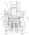
図1は成形装置1の構成を示す図、図2は成形装置1の正面部分断面図、図3は図2におけるA−A矢視断面図、図4は相対変位測定手段2の概要を示す図、図5はコントロールユニット3の構成を示す図、図6は成形装置1の動作を示すフローチャートである。
図1において、成形装置1は、成形処理装置4およびコントロールユニット3からなる。FIG. 1 is a diagram showing the configuration of the
In FIG. 1, the
図2,3において、成形処理装置4は、下板5、固定軸6、上板7、4本の支柱8,8,8,8、ガイド板9、大変位アクチュエータ10、3基の小変位アクチュエータ11,11,11、移動軸12、および3組の相対変位測定手段2,2,2からなる。
下板5は、厚みおよび重量を有する平面視が正方形の板材で形成されており、4隅には垂直に支柱8,…,8が固定されている。下板5の上面の中央部分には、被成形物Wを支持するための固定軸6が取り付けられている。また、下板5には、固定軸6と一定の間隔を有して固定軸6の外周を囲むように円筒状の下部チャンバ13が固定され、下部チャンバ13の外側には、下部チャンバ13の外周を上下に摺動し下部チャンバ13との間に一定の気密性を維持することができる円管状の気密リング14が設けられている。2 and 3, the molding apparatus 4 includes a
The
下板5の下面には、レーザ干渉計15,15,15を収容するための凹部16が設けられている。
また、下板5は、その下面の四隅にて、除振台50によって支持される。この、除振台50は、地面からの振動を成型処理装置4の本体に伝達させないよう設けられるものである。A
The
上板7は、平面視が下板5と同じ形状の厚みを有する板材で形成されており、上板7の上方に配され4隅に支柱8,…,8が固定されて下板5および4本の支柱8,…,8と一体化されている。
支柱8は、円形断面の棒体であり、下板5および上板7とともに成形処理装置4を支えるフレーム構造を形成している。The upper plate 7 is formed of a plate material having the same shape as the
The
ガイド板9は、平面視が下板5と同じ形状の厚みを有する板材で形成されており、上面には大変位アクチュエータ10の可動部17が固定的に連結され、下面には小変位アクチュエータ11,11,11が固定的に連結されている。ガイド板9の4隅には孔が設けられており、孔には短管(短い円管)18が嵌め込まれている。短管18内には支柱8が貫通しており、ガイド板9は、短管18の内周面が支柱8の外周面を摺動することにより、下板5と上板7との間において傾いたり水平方向にずれたりすることなく円滑に上下動可能となっている。 The guide plate 9 is formed of a plate material having the same shape as the
なお、短管18の内周面には、図示しない低摺動部材が周設され、短管18と支柱8との摺動が滑らかとなるよう構成してある。
大変位アクチュエータ10は、サーボモータ19、ボールネジ軸20、ボールネジ21、および可動部17などからなる。サーボモータ19は、上板7に固定されたモータ支持部22に取り付けられている。ボールネジ軸20は、サーボモータ19の回転軸に直結されており、下方のネジ部分が可動部17の上端に固定されたボールネジ21に螺合されている。可動部17はその下端がガイド板9に固定されているため、大変位アクチュエータ10は、サーボモータ19の回転により可動部17に固定されたガイド板9を上下動させる構成となっている。Note that a low sliding member (not shown) is provided around the inner peripheral surface of the
The
小変位アクチュエータ11は3基使用されており、いずれも伸縮方向が上下方向になるように並列に、かつ大変位アクチュエータ10の加圧中心軸を中心とする同ピッチ円上に3個等分に配置されて、ガイド板9の下面にそれぞれの一端が固定されている。各小変位アクチュエータ11,11,11の他端は、移動軸12の上面に固定的に連結されている。小変位アクチュエータ11は、ピエゾアクチュエータが荷重センサ23と一体化されたものが用いられ、小変位アクチュエータ11ごとの押しつけ力の測定が可能となっている。 Three
なお、ピエゾアクチュエータにはピエゾメカニック社製の高電圧予備付加付きピエゾアクチュエータ(歪ゲージ付き)PST1000/38/80US45などが好適である。
小変位アクチュエータ11として荷重センサ23が組み込まれていないものを使用する場合には、小変位アクチュエータ11,11,11と同数の荷重センサ23,23,23を各小変位アクチュエータ11,11,11の近傍に配置するのが好ましい。For the piezo actuator, a piezo actuator (with a strain gauge) PST1000 / 38 / 80US45 manufactured by Piezo Mechanic, etc. is suitable.
When the
そして、ガイド板9の下面には係止部材52が設けられている。係止部材52は、均等に12個の挿入穴がその周りに形成され、その挿入穴には、基部24の上面に固着されたボルト部材53,…,53が挿入されている。そして、係止部材52とボルト部材53,…,53との間には、バネ部材54,…,54が設けられている。これらの構成により、チャンバ28の内部が負圧(真空)にされた場合でも、小変位アクチュエータ11,11,11を構成するピエゾアクチュエータに過度の引っ張り力がかかって破損することがないようにしている。 A locking
移動軸12は、基部24、金型支持部25、および上部チャンバ26などからなる。基部24は、平面視の形状が円形であって、上面が小変位アクチュエータ11,11,11の他端に固定的に連結され、下面には金型27を支持するための金型支持部25が一体化されている。基部24の下面には、基部24の外縁の周りを囲むようにして下方に延びた上部チャンバ26が設けられている。上部チャンバ26、気密リング14、および下部チャンバ13は、上部チャンバ26の下端に気密リング14の上端が当接することによりこれらの内側に形成されるチャンバ28をある程度の気密状態に保つことが可能なように構成されている。 The moving
なお、下部チャンバ13の外周に溝が形成され、その溝にOリング等の部材51が嵌めれ、チャンバ28を気密状態に保つことができるように構成している。
相対変位測定手段2は、貫通孔29、第1反射器30、透過窓31、第2反射器32、およびレーザ干渉計15からなる。
貫通孔29は、チャンバ28と凹部16とを垂直に貫通する断面が円形の孔であり、平面視において基部24の中心と各小変位アクチュエータ11,11,11とを結ぶそれぞれの線上の小変位アクチュエータ11近傍に設けられている(図3参照)。A groove is formed on the outer periphery of the
The relative displacement measuring means 2 includes a through
The through
第1反射器30は、貫通孔29がチャンバ28に開口する部分に設けられ、凹部16のレーザ干渉計15から貫通孔29を通って入射した光を180度変換してレーザ干渉計15に向けて反射するためのものである。
透過窓31は、貫通孔29がチャンバ28に開口する部分に第1反射器30の横に並べて設けられている。透過窓31は、レーザ干渉計15から貫通孔29を通って入射した光をチャンバ28に透過させるためのものであり、レーザ光を透過するガラスなどで形成されている。The
The
透過窓31および第1反射器30は、貫通孔29の開口部を閉じてチャンバ28の気密を維持できるように構成されて固定軸6に組み込まれている。
第2反射器32は、金型27の近傍における透過窓31を透過する光の光路上に設けられ、入射した光を180度変換してレーザ干渉計15に向けて反射するためのものである。第2反射器32を金型27に付属させて形成してもよい。The
The
レーザ干渉計15は、光源33、分配器34、屈折器35、およびデテクター36などからなる。
光源33には、単一波長の半導体レーザ光源が使用される。
分配器34は、光源33から発せられ集光されたレーザビームを、透過光TL1と透過光TL1に対して90度屈折する反射光RL1との2光束に分配する働きをする。The
As the
The
屈折器35は、分配された反射光RL1を透過光TL1と平行になるように屈折させる。
デテクター36は、第1反射器30で反射して戻った透過光TL2と、第2反射器32で反射して戻った反射光RL2とが合波された合成波を検知し、検知された合成波から反射光RL2に対する透過光TL2の位相差を検出して、第1反射器30と第2反射器32との相対距離を求める。The
The
なお、レーザ干渉計15を用いて行う相対距離の測定方法は公知である。
レーザ干渉計15,15,15は、いずれも、透過光TL1が第1反射器30に入射しかつ反射光RL1が第2反射器32に入射するように、凹部16に位置決めされ固定されている。
コントロールユニット3は、インタフェース37、第1押しつけ判別部38、第2押しつけ判別部39、平行判別部40、記憶部41、大変位アクチュエータドライバ42、および小変位アクチュエータドライバ43,43,43などからなる。A method for measuring the relative distance using the
The
The
コントロールユニット3は、レーザ干渉計15,15,15が測定した相対距離および荷重センサ23が測定した荷重に基づいて大変位アクチュエータ10および小変位アクチュエータ11,11,11をコントロールし、成形処理装置4における成形処理を適切に行うことができるように移動軸12の上下動を制御する働きをする。成形処理におけるコントロールユニット3の各構成の機能については、後に成形処理装置4の動作の説明とともに説明する。 The
第1押しつけ判別部38、第2押しつけ判別部39、および平行判別部40は、制御プログラム、CPU(マイクロコンピュータ)、RAMなどにより実現される。記憶部41はRAMおよびハードディスクなどの外部記憶装置により、インタフェース37、大変位アクチュエータドライバ42、および小変位アクチュエータドライバ43,43,43は専用の電子回路により実現される。コントロールユニット3には図示しないキーボード、マウスなどの入力装置、およびLCDまたはCRTなどの表示装置が接続され、コントロールユニット3の動作に関する種々の条件を入力しまたは変更し、またコントロールユニット3の動作を監視することが可能となっている。 The first
次に、コントロールユニット3が成形処理装置4を制御して行う、被成形物Wへの金型27による成形処理について説明する。
成形処理は、チャンバ28が気密リング14によって気密にされ、連通する図示しない真空ポンプによりチャンバ28が減圧にされた状態で行われる。
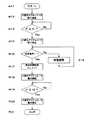
成形処理が開始されると、サーボモータ19が始動して大変位アクチュエータ10が降下動作を開始する(#12)。可動部17の降下とともに可動部17に固定されたガイド板9、ガイド板9に固定された小変位アクチュエータ11,11,11、小変位アクチュエータ11,11,11に固定的に連結されている移動軸12、および移動軸12に支持された金型27が一体となって降下する。気密リング14は、その上端が上部チャンバ26の下端に当接した状態で移動軸12の降下とともに降下し、チャンバ28の気密状態は維持される。チャンバ28の気密状態は、この後に行われる小変位アクチュエータ11,11,11の動作時にも同様にして維持される。Next, a description will be given of a molding process performed by the
The molding process is performed in a state where the
When the molding process is started, the
サーボモータ19の回転の管理は、第1押しつけ判別部38が大変位アクチュエータドライバ42の動作を制御することにより行われる。大変位アクチュエータ10が降下動作を行っているときの各荷重センサ23,23,23により検出された荷重の信号は、インタフェース37によりA/D変換され、予め設定され記憶部41に記憶された荷重Pjと第1押しつけ判別部38によって比較される(#13)。 Management of the rotation of the
金型27が被成形物Wに接触し、各荷重センサ23,23,23で検出された荷重Pのいずれかが荷重Pj以上になると(#13でYes)、第1押しつけ判別部38は大変位アクチュエータ10の降下動作を停止させる(#14)。
この後、各荷重センサ23,23,23で検出される荷重Pが全て同一となるまで、第2押しつけ判別部39は、最大荷重を検出した荷重センサ23が一体化された小変位アクチュエータ11を除く小変位アクチュエータ11,11に押しつけ動作をさせるため、該当する小変位アクチュエータドライバ43,43を動作させる(#15,#16)。ここでいう小変位アクチュエータドライバ43は、第2押しつけ判別部39の指示に従い小変位アクチュエータ11に印加するための電圧を発生させるものをいう。なお、「荷重Pが全て同一」とは、測定誤差を考慮して一定の幅を持たせた「同一と認められる範囲」の意であり、完全な同一を意味するものではない。以下に記載する「同一」についても「同一と認められる範囲」を意味するものとする。When the
Thereafter, until the loads P detected by the
各荷重センサ23,23,23で検出された荷重Pが全て同一と判断されると(#15でYes)、そのときの各レーザ干渉計15,15,15で測定された相対距離Lをそれぞれの原点位置(Ls=L)として記憶部41に記憶する(#17)。
続いて、第2押しつけ判別部39は各小変位アクチュエータドライバ43,43,43を制御して、小変位アクチュエータ11,11,11に被成形物Wへの金型27の押しつけ動作を行わせる(#18)。この時、平行判別部40は、各小変位アクチュエータ11,11,11近傍のレーザ干渉計15,15,15が測定したそれぞれの相対距離Lと原点位置Lsとの差L−Ls(以下、それぞれの「押しつけ距離H」という)に基づいて、その後の押しつけ後の押しつけ距離Hが同一となるように、各小変位アクチュエータ11,11,11の動作を制御する第2押しつけ判別部39に小変位アクチュエータ11ごとの指示を与える。具体的には、目標押しつけ距離を都度想定し、各押しつけ距離Hが同時に目標押しつけ距離となるように、各小変位アクチュエータ11,11,11の動作速度をレーザ干渉計15,15,15が測定したそれぞれの最新の相対距離Lに応じて制御する。そして、このような各小変位アクチュエータ11,11,11の動作速度の制御は、順次目標押しつけ距離を更新しながら、各レーザ干渉計15,15,15が測定した相対距離Lから算出された押しつけ距離Hが予め設定した最終押しつけ距離Hj以上になるまで行われる(#19)。第2押しつけ判別部39が、押しつけ距離Hが最終押しつけ距離Hj以上になったと判断したとき、小変位アクチュエータ11,11,11による押しつけ動作が停止される(#19でYes、#20)。If it is determined that the loads P detected by the
Subsequently, the second pressing determining
なお、仮定される目標押しつけ距離は、最初は最終押しつけ距離Hjより小さな値が選択され、最終的には最終押しつけ距離Hjが選択される。
小変位アクチュエータ11,11,11による押しつけ動作の停止により成形処理は完了し(#21)、金型27が上昇して被成形物Wの取り出しが可能となる。
成形装置1による成形処理では、本格的な金型27の被成形物Wへの押しつけ動作の前に一旦各荷重センサ23,23,23で検出された荷重Pが全て同一となるように調整し(#15,#16)、その後の押しつけ動作において各レーザ干渉計15,15,15が測定する相対距離Lに基づく押しつけ距離Hが同一となるように各小変位アクチュエータ11,11,11を制御するので(#18)、被成形物Wと金型27との平行度を保ちながらかつ被成形物Wの厚み方向の成形の寸法精度を高めることが可能となる。The assumed target pressing distance is initially selected to be smaller than the final pressing distance Hj, and finally the final pressing distance Hj is selected.
When the pressing operation by the
In the molding process by the
大変位アクチュエータの降下動作の停止(#14)を、特願2005−303218号に記載されているように、サーボモータ19の回転(大変位アクチュエータ10の押しつけ動作)をロータリエンコーダからのパルス信号の累積値として検出し、押しつけを行わないときのパルス信号の累積値とパルス信号の累積値増加速度との関係(動作速度パターン)と比較して、押しつけ時の累積値増加速度が動作速度パターンから所定量逸脱したときに行うようにしてもよい。 As described in Japanese Patent Application No. 2005-303218, the lowering operation of the large displacement actuator is stopped (# 14) by rotating the servo motor 19 (the pressing operation of the large displacement actuator 10) by the pulse signal from the rotary encoder. Compared to the relationship (operation speed pattern) between the cumulative value of the pulse signal when it is detected as a cumulative value and the pulse signal is not pressed and the cumulative value increase speed of the pulse signal (operation speed pattern), the cumulative value increase speed at the time of pressing is It may be performed when a predetermined amount deviates.
各小変位アクチュエータ11,11,11による押しつけ動作の終了は、全てのレーザ干渉計15,15,15が測定した相対距離Lに基づく押しつけ距離Hが最終押しつけ距離Hj以上になったときに行うのが好ましいが、いずれかの押しつけ距離Hが最終押しつけ距離Hj以上になったとき、または2つ以上の押しつけ距離Hが最終押しつけ距離Hj以上になったときに行うようにしてもよい。 The pressing operation by each
成形処理の完了後、金型27と被成形物Wとを引き離すときに被成形物Wの転写パターンが崩れないようにするには、引き離しの際に各小変位アクチュエータ11,11,11を伸縮させかつその伸縮速度を制御したり、各小変位アクチュエータ11,11,11を微小振幅(高周波)で振動させると効果的である。微小振動は、例えば、ピエゾアクチュエータにより実現される。 After the molding process is completed, in order to prevent the transfer pattern of the molding object W from collapsing when the
成型装置では、成形時に被成形物Wが加熱または冷却を必要とする場合、被成形物Wに応じた適切な条件で加熱または冷却が行われる。ただし、原点位置Lsを記憶(確定)する時(#17)の被成形物Wの温度は、被成形物Wが金型27に接触するだけで変形するほどの高温であってはならない。被成形物Wが加熱を必要とする場合には、固定軸6および移動軸12に加熱手段が組み込まれる。このとき、加熱手段によって発生する熱が小変位アクチュエータ11,11,11および相対変位測定手段2,2,2などの精密機器に悪影響を与えないように、固定軸6、移動軸12、下部チャンバ13、および上部チャンバ26に適切な断熱手段が設けられる。 In the molding apparatus, when the molding target W needs to be heated or cooled during molding, heating or cooling is performed under appropriate conditions according to the molding target W. However, the temperature of the workpiece W when the origin position Ls is stored (determined) (# 17) must not be so high that the workpiece W is deformed only by contacting the
また、成形処理の完了後、転写されたパターンが被成形物Wに確実に固定されるように、金型27と被成形物Wとを密着したまま滴当な温度まで冷却することが考えられる。このときにお互いが被成形物Wの収縮により離れてしまわないように金型27の位置を小変位アクチュエータ11,11,11で制御するのが好ましい。
上述の実施形態において、大変位アクチュエータ10および小変位アクチュエータ11は、上述した形式のものに限られず種々のものを使用することができる。大変位アクチュエータ10は、2つ以上のアクチュエータで構成することができる。また、小変位アクチュエータ11、荷重センサ23、および相対変位測定手段2の数は、何れも3基または3組以上であれば上記実施形態の数に限られない。例えば、図7に示されるように、小変位アクチュエータ11、荷重センサ23、および相対変位測定手段2を何れも4基または4組用いて成形装置を構成することができる(図7において図3と同一の符号を付された部位の構成は図3における構成と同一である)。ただし、小変位アクチュエータ11、荷重センサ23、および相対変位測定手段2の数は全て同じであることが好ましく、また、これらを組み合わせた1組の小変位アクチュエータ11、荷重センサ23、および相対変位測定手段2は、それぞれが移動軸12の軸心からの略同一ラジアル方向に位置するように配置するのが好ましい。In addition, after the molding process is completed, it is conceivable that the
In the above-described embodiment, the
小変位アクチュエータ11,11,11を、金型27の押しつけ方向から傾斜させて設けることができる。その場合、加重センサ23,23,23の荷重の測定値はそれぞれの小変位アクチュエータ11,11,11の傾きを考慮した値に換算される。
その他、成形装置1、および成形装置1の各構成または全体の構造、形状、寸法、個数、材質などは、本発明の趣旨に沿って適宜変更することができる。The
In addition, each structure of the shaping |
本発明は、凹凸が設けられた金型を被成形物に押しつけて金型の凹凸を被成形物に転写するナノインプリント装置に利用することができる。 INDUSTRIAL APPLICABILITY The present invention can be used for a nanoimprint apparatus that presses a mold provided with unevenness against a molding object and transfers the unevenness of the mold to the molding object.
1 成形装置
2 距離測定手段(相対変位測定手段)
3 制御手段(コントロールユニット)
6 被成形物を支持する部材(固定軸)
10 大変位アクチュエータ
11 小変位アクチュエータ
12 型を支持する部材(移動軸)
23 荷重測定手段(荷重センサ)
27 型(金型)
W 被成型物1 Forming device 2 Distance measuring means (relative displacement measuring means)
3 Control means (control unit)
6 Member that supports the workpiece (fixed shaft)
10
23 Load measuring means (load sensor)
27 type (mold)
W molding
Claims (5)
Translated fromJapanese大変位アクチュエータにより前記型に押しつけ動作を行わせ、
前記押しつけ動作が所定の要件を満たしたら前記大変位アクチュエータの押しつけ動作を停止し、
前記押しつけ動作の結果前記型に生じた反力または前記型を支持する部材に生じた反力を押しつけ方向に直交する方向における3カ所以上の異なる場所で測定し、
前記大変位アクチュエータと前記型との間に設けられ前記大変位アクチュエータよりも小さな変位の制御が可能な並列に配置された3基以上の小変位アクチュエータに対して測定した前記反力のすべてが略同一になるように押しつけ動作をさせ、
前記型または前記型を支持する部材と前記被成形物または前記被成形物を支持する部材との距離を距離測定手段により3カ所以上の異なる場所で測定してそれぞれを初期距離として記憶し、
前記距離測定手段が測定した距離と前記初期距離との差が設定値以上になるまでそれぞれの前記小変位アクチュエータに押しつけ動作をさせる
ことを特徴とする成形方法。A molding method in which a mold is pressed against a molding, and the unevenness formed on the mold is transferred to the molding,
The large displacement actuator is used to press against the mold,
When the pressing operation satisfies a predetermined requirement, the pressing operation of the large displacement actuator is stopped,
Measuring the reaction force generated in the mold as a result of the pressing operation or the reaction force generated in the member supporting the mold at three or more different locations in the direction orthogonal to the pressing direction;
All of the reaction forces measured with respect to three or more small displacement actuators arranged in parallel between the large displacement actuator and the mold and capable of controlling a smaller displacement than the large displacement actuator are substantially all. Press to make it the same,
The distance between the mold or the member supporting the mold and the molding or the member supporting the molding is measured at three or more different locations by distance measuring means, and each is stored as an initial distance,
The molding method, wherein the small displacement actuators are pressed until the difference between the distance measured by the distance measuring means and the initial distance is equal to or greater than a set value.
前記3カ所以上の異なる場所で測定した前記型に生じた反力または前記型を支持する部材に生じた反力のいずれかまたは全てが特定の値以上になったことである
請求項1に記載の成形方法。The predetermined requirement for stopping the pressing operation of the large displacement actuator is:
The reaction force generated in the mold measured in the three or more different places or the reaction force generated in a member supporting the mold is at least a specific value. Molding method.
前記型に連続し前記型を前記被成形物に押しつける方向に移動させる互いに並列に配置された小変位の制御が可能な3つ以上の小変位アクチュエータと、
前記小変位アクチュエータに連続し前記小変位アクチュエータを前記型に近づける方向に移動させ前記小変位アクチュエータよりも大変位の制御が可能な大変位アクチュエータと、
前記型を前記被成形物に押しつける方向に移動させたときに前記型に生じる反力または前記型を支持する部材に生じる反力を押しつけ方向に直交する方向における3カ所以上の異なる場所で測定する荷重測定手段と、
前記型または前記型を支持する部材と前記被成形物または前記被成形物を支持する部材との距離を3カ所以上の異なる場所で測定する距離測定手段と、を有し、
前記荷重測定手段の測定結果に基づいて前記大変位アクチュエータの押しつけ動作を制御し、前記距離測定手段の測定結果に基づいて前記小変位アクチュエータの押しつけ動作を制御するように構成されてなる
ことを特徴とする成形装置。A molding apparatus that presses a mold against a molding object and transfers the irregularities formed on the mold to the molding object,
Three or more small-displacement actuators that are arranged in parallel with each other and that are arranged in parallel to move the mold in a direction of pressing the mold against the molding;
A large displacement actuator that is continuous with the small displacement actuator and moves the small displacement actuator in a direction closer to the mold and can control a larger displacement than the small displacement actuator;
The reaction force generated in the mold or the reaction force generated in the member supporting the mold when the mold is moved in the direction in which the mold is pressed against the workpiece is measured at three or more different locations in the direction orthogonal to the pressing direction. Load measuring means;
Distance measuring means for measuring the distance between the mold or the member supporting the mold and the molding or the member supporting the molding at three or more different locations;
The pressing operation of the large displacement actuator is controlled based on the measurement result of the load measuring means, and the pressing operation of the small displacement actuator is controlled based on the measurement result of the distance measuring means. A forming device.
請求項3に記載の成形装置。The molding apparatus according to claim 3, further comprising a control unit that controls each pressing operation of the small displacement actuator so that the measurement results of the distance measuring units are substantially the same.
請求項3または請求項4に記載の成形装置。The molding apparatus according to claim 3, wherein the small displacement actuator is configured to vibrate at a high frequency after the pressing operation by the small displacement actuator is completed.
Priority Applications (1)
| Application Number | Priority Date | Filing Date | Title |
|---|---|---|---|
| JP2005375338AJP2007180178A (en) | 2005-12-27 | 2005-12-27 | Forming method and apparatus thereof |
Applications Claiming Priority (1)
| Application Number | Priority Date | Filing Date | Title |
|---|---|---|---|
| JP2005375338AJP2007180178A (en) | 2005-12-27 | 2005-12-27 | Forming method and apparatus thereof |
Publications (1)
| Publication Number | Publication Date |
|---|---|
| JP2007180178Atrue JP2007180178A (en) | 2007-07-12 |
Family
ID=38305090
Family Applications (1)
| Application Number | Title | Priority Date | Filing Date |
|---|---|---|---|
| JP2005375338APendingJP2007180178A (en) | 2005-12-27 | 2005-12-27 | Forming method and apparatus thereof |
Country Status (1)
| Country | Link |
|---|---|
| JP (1) | JP2007180178A (en) |
Cited By (5)
| Publication number | Priority date | Publication date | Assignee | Title |
|---|---|---|---|---|
| JP2007305944A (en)* | 2006-05-15 | 2007-11-22 | Univ Waseda | Transfer device and transfer method |
| JP2008132711A (en)* | 2006-11-29 | 2008-06-12 | Toshiba Mach Co Ltd | Transfer apparatus and transfer method |
| JP2010080918A (en)* | 2008-08-19 | 2010-04-08 | Asml Netherlands Bv | Imprint lithography |
| JP2010272860A (en)* | 2009-05-19 | 2010-12-02 | Asml Netherlands Bv | Imprint lithography apparatus |
| US8772179B2 (en) | 2012-02-20 | 2014-07-08 | Kabushiki Kaisha Toshiba | Pattern forming method, pattern forming apparatus, and method for manufacturing semiconductor device |
- 2005
- 2005-12-27JPJP2005375338Apatent/JP2007180178A/enactivePending
Cited By (6)
| Publication number | Priority date | Publication date | Assignee | Title |
|---|---|---|---|---|
| JP2007305944A (en)* | 2006-05-15 | 2007-11-22 | Univ Waseda | Transfer device and transfer method |
| JP2008132711A (en)* | 2006-11-29 | 2008-06-12 | Toshiba Mach Co Ltd | Transfer apparatus and transfer method |
| JP2010080918A (en)* | 2008-08-19 | 2010-04-08 | Asml Netherlands Bv | Imprint lithography |
| JP2010272860A (en)* | 2009-05-19 | 2010-12-02 | Asml Netherlands Bv | Imprint lithography apparatus |
| US8845320B2 (en) | 2009-05-19 | 2014-09-30 | Asml Netherlands B.V. | Imprint lithography apparatus |
| US8772179B2 (en) | 2012-02-20 | 2014-07-08 | Kabushiki Kaisha Toshiba | Pattern forming method, pattern forming apparatus, and method for manufacturing semiconductor device |
Similar Documents
| Publication | Publication Date | Title |
|---|---|---|
| JP6304934B2 (en) | Imprint apparatus and article manufacturing method | |
| JP5824379B2 (en) | Imprint apparatus, imprint method, and article manufacturing method | |
| JP6497849B2 (en) | Imprint apparatus and article manufacturing method | |
| JP6748461B2 (en) | Imprint apparatus, method of operating imprint apparatus, and article manufacturing method | |
| WO2010087082A1 (en) | Device of producing wafer lens and method of producing wafer lens | |
| KR20100040243A (en) | Precise press apparatus and press load control method therein | |
| KR20030040378A (en) | Methods for high-precision gap and orientation sensing between a transparent template and substrate for imprint lithography | |
| KR20060127804A (en) | Processing equipment, processing method and chip manufacturing method | |
| WO2002017382A1 (en) | Alignment device | |
| KR20160121893A (en) | 2 axes linear motion hollow stage using flexure mechanism | |
| JP2007180178A (en) | Forming method and apparatus thereof | |
| US20160257060A1 (en) | Imprint apparatus, imprint method, and article manufacturing method | |
| JP5196743B2 (en) | Processing method and apparatus, and device manufacturing method | |
| JP5666082B2 (en) | Transfer device and press device | |
| KR100688393B1 (en) | Method for manufacturing microstructures and manufacturing system therefor | |
| KR20020011923A (en) | Apparatus for molding precision element, and method for molding the same | |
| WO2024075671A1 (en) | Alignment device and alignment method | |
| JP2014110384A (en) | Imprint device, imprint method, and device manufacturing method | |
| JP2000349043A (en) | Precise focusing method for rectangular beam | |
| JP7406338B2 (en) | Stage device, stage device adjustment method, and article manufacturing method | |
| KR20240171024A (en) | Imprinting apparatus, imprinting method, and product manufacturing method | |
| JP2007103799A (en) | Transfer equipment for transferring shape | |
| JP2018206815A (en) | Mold, imprint apparatus, and manufacturing method of article | |
| JP2007183189A (en) | Shape measuring apparatus | |
| Shao et al. | Strategy for a loading force induced overlay position shift in step imprint lithography |