JP2007178925A - Imaging device, strobe device, and control method of strobe device - Google Patents
Imaging device, strobe device, and control method of strobe deviceDownload PDFInfo
- Publication number
- JP2007178925A JP2007178925AJP2005380162AJP2005380162AJP2007178925AJP 2007178925 AJP2007178925 AJP 2007178925AJP 2005380162 AJP2005380162 AJP 2005380162AJP 2005380162 AJP2005380162 AJP 2005380162AJP 2007178925 AJP2007178925 AJP 2007178925A
- Authority
- JP
- Japan
- Prior art keywords
- light emission
- light
- light emitting
- strobe
- emission amount
- Prior art date
- Legal status (The legal status is an assumption and is not a legal conclusion. Google has not performed a legal analysis and makes no representation as to the accuracy of the status listed.)
- Withdrawn
Links
Images


Landscapes
- Exposure Control For Cameras (AREA)
- Stroboscope Apparatuses (AREA)
- Studio Devices (AREA)
Abstract
Description
Translated fromJapanese本発明は、撮像装置、ストロボ装置、及びストロボ装置の制御方法に関する。 The present invention relates to an imaging device, a strobe device, and a control method for the strobe device.
従来、撮像装置で用いられるストロボ装置の露出制御方式には、いわゆる外測調光と称されるものと、TTL調光と称されるものがある。 2. Description of the Related Art Conventionally, there are two types of exposure control methods for strobe devices used in imaging devices, so-called external metering light and TTL light control.
外測調光では、被写体に向けてストロボ光を照射し、被写体からの反射光を、撮影レンズとは異なる光学系を通じて受光して受光量を測定して積分し、その積分値が所定量に達した時点でストロボ装置の発光を停止するように制御する。 In external metering light, a strobe light is emitted toward the subject, the reflected light from the subject is received through an optical system different from the taking lens, the received light amount is measured and integrated, and the integrated value becomes a predetermined amount. When it reaches, the flash unit is controlled to stop emitting light.
一方、TTL調光では、被写体に向けてストロボ光を照射し、被写体からの反射光を、撮影レンズを通して測光部により測光して積分し、その積分値が所定量に達した時点でストロボ装置の発光を停止するように制御する。 On the other hand, in TTL dimming, strobe light is emitted toward the subject, and the reflected light from the subject is measured by the photometry unit through the photographing lens and integrated, and when the integrated value reaches a predetermined amount, Control to stop light emission.
上述したようなストロボ装置では、一般に、光源としてキセノン管が広く使用されているが、その発光特性と発光停止時に実際に発光が止まるまでのオーバーシュートについて、図12を参照して説明する。 In the strobe device as described above, a xenon tube is generally widely used as a light source. The light emission characteristics and overshoot until the light emission actually stops when the light emission is stopped will be described with reference to FIG.
図12に示すように、時間t0で通電されてキセノン管からの光放射が始まると、図中に示すように発光強度が増加する。そして、キセノン管に流れる電流がストロボ発光用の電源とキセノン管のインピーダンスにより定まる最大電流に到達した後は、徐々に発光強度が減少する。As shown in FIG. 12, when light emission from the xenon tube is started at time t0 , the emission intensity increases as shown in the figure. Then, after the current flowing through the xenon tube reaches the maximum current determined by the power supply for strobe light emission and the impedance of the xenon tube, the emission intensity gradually decreases.
撮像装置では、時間t0から被写体で反射したキセノン管の光を受光して受光量を測定して積分していき、所定受光量に到達したことを検出すると、ストロボの発光を停止させる。この場合、被写体が近いほど多くの光が反射することになるため、被写体が遠くにある場合よりも、早く所定受光量に到達する。The imaging device receives light from the xenon tube reflected from the subject from time t0 and measures and integrates the received light amount. When it detects that the predetermined received light amount has been reached, the strobe light emission is stopped. In this case, the closer the subject is, the more light is reflected. Therefore, the predetermined amount of received light is reached earlier than when the subject is far away.
しかしながら、時間t1で所定受光量に達し、キセノン管への通電を止めたとしても、不図示の発光遮断回路の応答遅れやキセノン管のイオン消失に時間がかかるため、実際にストロボ装置からの発光が無くなるのは、時間t2となってしまう。同様に、被写体が遠く、時間t3でストロボ装置への通電を停止した場合にも、上述した理由により実際の発光停止は時間t4となってしまう。However, even if the predetermined amount of light is reached at time t1 and the energization of the xenon tube is stopped, the response delay of the light emission cutoff circuit (not shown) and the disappearance of ions of the xenon tube take time, It is time t2 that light emission is lost. Similarly, even when the subject is far away and the power supply to the strobe device is stopped at time t3 , the actual light emission stop is time t4 for the reason described above.
発光停止指示後に実際に発光停止に至るまでの時間は、回路の応答速度などにより決まり、図12に示すように発光停止指示時の発光強度の大きさに関わらずあまり変わらない。従って、図12から明らかなように、発光時間が短い程、オーバーシュート分が発光量全体にしめる割合が多くなり、露出オーバーとなる傾向が強いという問題があった。 The time until the light emission is actually stopped after the light emission stop instruction is determined by the response speed of the circuit, etc., and does not change much regardless of the magnitude of the light emission intensity at the time of the light emission stop instruction as shown in FIG. Accordingly, as is apparent from FIG. 12, there is a problem that as the light emission time is shorter, the ratio of the overshoot amount to the entire light emission amount increases and the tendency to overexpose is strong.
一方、近年、白色発光ダイオードを使用したストロボ装置が提案されている。図13は白色発光ダイオードの発光波形を示している。図13に示すように、白色発光ダイオードに流れる電流が高くなるにつれて(I0<I1<I2)、発光強度も高くなる。また、白色発光ダイオードは、電流が流れている間中フラットに発光すると共に、キセノン管と比べて時間に対する応答性に優れ、微小発光量の制御が容易であるという利点がある。その上、発光寿命が長く、消費電力も少ない。On the other hand, in recent years, a strobe device using a white light emitting diode has been proposed. FIG. 13 shows a light emission waveform of the white light emitting diode. As shown in FIG. 13, as the current flowing through the white light emitting diode increases (I0 <I1 <I2 ), the emission intensity also increases. In addition, the white light emitting diode has advantages that it emits light flat while current is flowing, has excellent time response compared to a xenon tube, and can easily control a minute light emission amount. In addition, the light emission life is long and the power consumption is low.
なお、上述したようなストロボ装置の発光タイミングとしては、シャッター機構のシャッター全開直後に発光させる先幕シンクロモードと、シャッター機構のシャッター閉動作の所定時間前に発光させる後幕シンクロモードとに大別される。 Note that the flash timing of the strobe device as described above is roughly divided into a front curtain sync mode that emits light immediately after the shutter is fully opened and a rear curtain sync mode that emits light a predetermined time before the shutter closing operation of the shutter mechanism. Is done.
通常、先幕シンクロモードでストロボ撮影が行われることが多いが、動きのある被写体を先幕シンクロモードによるストロボ撮影を行った場合に、次のような問題が生じていた。即ち、シャッターが開いている時間内の極めて初期の段階で発光が行われるため、特に被写体が動いている場合には、被写体の初期の動作部分が明確に写り、時間的に新しい動作部分が光の残像として写り込むといった、一般的には不自然な画像となる。 Usually, strobe shooting is often performed in the first-curtain sync mode, but the following problems have arisen when strobe shooting is performed on a moving subject in the first-curtain sync mode. In other words, since light is emitted at an extremely early stage within the time when the shutter is open, especially when the subject is moving, the initial motion part of the subject is clearly shown, and the new motion part is temporally light. In general, the image becomes an unnatural image, such as an afterimage.
これに対し、後幕シンクロモードにより同等の条件下でストロボ撮影を行った場合には、シャッターが開いている時間内のきわめて後期の段階で発光が行われる。従って、時間的に古い動作部分が被写体像の残像として写り込み、時間的に新しい部分が明確に写った写真となるため、特に被写体が動いている場合には自然な画像となる。しかし、後幕シンクロモードでは、シャッター秒時が比較的長い場合には、レリ−ズ操作のタイミングとストロボ装置の発光タイミングとにタイムラグが生じ、撮影者の意図するタイミングで明確な被写体像が写った画像を得られない場合もある。 On the other hand, when flash photography is performed under the same conditions in the rear curtain sync mode, light emission is performed at a very late stage within the time when the shutter is open. Therefore, the motion part that is old in time is captured as an afterimage of the subject image, and the new part is clearly captured in time, so that a natural image is obtained particularly when the subject is moving. However, in the second curtain sync mode, when the shutter speed is relatively long, there is a time lag between the timing of the release operation and the flash timing of the strobe device, and a clear subject image is captured at the timing intended by the photographer. You may not be able to get the correct image.
このため、スローシンクロ撮影において、ストロボ発光のタイミングを制御することにより、被写体の動きが自然に見える写真を撮影できるようにしたカメラが提案されている(例えば、特許文献1参照)。 For this reason, in slow sync photography, a camera has been proposed that can take a picture in which the movement of a subject looks natural by controlling the timing of strobe light emission (see, for example, Patent Document 1).
上述したキセノン管を用いた場合の露出オーバーを解決するためには、回路の応答速度を早めることが考えられるが、それにも限界があり、またコストもかかってしまうという問題がある。また、他の解決手段として、発光時の発光量をTTL調光方式で積分して調光するTTL調光システムにおいて、ISO感度に応じて調光レベルを補正する方法が提案されている(例えば、特許文献2参照)。しかし、調光レベルを補正するだけでは、近距離の被写体を撮影する場合やレンズが明るい(撮影絞りが開放に近い)場合に対する露出オーバーは解決できない。 In order to solve the overexposure when the above-described xenon tube is used, it is conceivable to increase the response speed of the circuit. However, there is a problem in that there is a limit and the cost is increased. As another solution, there has been proposed a method for correcting the light control level according to the ISO sensitivity in a TTL light control system that performs light control by integrating the light emission amount during light emission by the TTL light control method (for example, , See Patent Document 2). However, overcorrection cannot be solved only by correcting the light control level when photographing a subject at a short distance or when the lens is bright (the photographing aperture is close to full open).
また、シンクロモード撮影を行う際、被写体輝度が低かったり、周囲が暗く、被写体像の残像を写すために充分な周辺光量を得られない場合がある。こういった場合、キセノン管が発光している時間のみの被写体像が撮影され、それ以外の時間は、例え露光中であっても被写体像が撮影されないため、特に被写体が動いている場合に、その動きを表現することができないという問題点があった。 In addition, when performing sync mode shooting, there may be a case where the subject brightness is low or the surroundings are dark, and a sufficient amount of peripheral light cannot be obtained to capture an afterimage of the subject image. In such a case, the subject image is taken only during the time when the xenon tube is emitting light, and the subject image is not taken during other times, for example, even during exposure, so when the subject is moving, There was a problem that the movement could not be expressed.
一方、白色発光ダイオードはキセノン管に比べて光量が乏しいたため、白色発光ダイオードのみを使用した場合に、カメラの撮影に必要な発光量を得ることができないという問題があった。 On the other hand, since the white light emitting diode has a smaller amount of light than the xenon tube, there is a problem that when only the white light emitting diode is used, it is not possible to obtain a light emission amount necessary for camera photography.
本発明は上記問題点を鑑みてなされたものであり、ストロボ装置において、大発光量から小発光量に至るまで、適正な実発光量の光を発光できるようにすることを目的とする。 The present invention has been made in view of the above problems, and an object of the present invention is to enable a strobe device to emit light having an appropriate actual light emission amount from a large light emission amount to a small light emission amount.
上記目的を達成するために、本発明の撮像装置は、閃光を発光する第1の発光手段と、一定強度の光を持続的に発光する第2の発光手段とを有するストロボ手段と、前記第1の発光手段と、前記第2の発光手段の発光量及び発光タイミングを制御する制御手段とを有する。 In order to achieve the above object, an imaging apparatus according to the present invention includes a strobe unit having a first light emitting unit that emits flash light and a second light emitting unit that continuously emits light having a certain intensity, 1 light emitting means, and a control means for controlling the light emission amount and the light emission timing of the second light emitting means.
好ましくは、上記撮像装置は、被写体輝度に応じて、撮影に必要な前記ストロボ手段の発光量と、露光時間とを取得する取得手段を更に有し、前記制御手段は、前記第1の発光手段の発光量と、前記第2の発光手段の発光量との合計が、前記ストロボ手段の発光量になると共に、前記露光時間内に前記第1の発光手段の発光が終了するように、前記第1の発光手段及び前記第2の発光手段の発光量及び発光タイミングを制御する Preferably, the imaging apparatus further includes an acquisition unit that acquires a light emission amount and an exposure time of the strobe unit necessary for photographing according to subject brightness, and the control unit includes the first light emission unit. The total light emission amount of the second light emission unit and the light emission amount of the second light emission unit become the light emission amount of the strobe unit, and the light emission of the first light emission unit is completed within the exposure time. Controls the light emission amount and the light emission timing of the first light emitting means and the second light emitting means.
閃光を発光する第1の発光手段と、一定の発光強度の光を持続的に発光する第2の発光手段とを有する、撮像装置と連携して用いられるストロボ装置の制御方法であって、被写体輝度に応じて、撮影に必要な前記ストロボ装置の発光量と露光時間とを取得する取得工程と、前記第1の発光手段の発光量と、前記第2の発光手段の発光量との合計が、前記取得手段により取得した前記ストロボ手段の発光量になると共に、前記露光時間内に前記第1の発光手段の発光が終了するように、前記第1の発光手段及び前記第2の発光手段の発光量及び発光タイミングを決定する発光時間決定工程と、前記決定した発光量及び発光タイミングに基づいて、前記第1の発光手段及び前記第2の発光手段を制御する制御工程とを有する。 A control method of a strobe device used in cooperation with an imaging device, comprising: a first light emitting unit that emits flash light; and a second light emitting unit that continuously emits light having a constant light emission intensity. The acquisition step of acquiring the light emission amount and exposure time of the strobe device necessary for photographing according to the luminance, the total light emission amount of the first light emitting unit, and the light emission amount of the second light emitting unit is The first light emitting means and the second light emitting means are configured so that the light emission amount of the strobe means acquired by the acquisition means is reached and the light emission of the first light emitting means is completed within the exposure time. A light emission time determination step for determining a light emission amount and a light emission timing; and a control step for controlling the first light emission means and the second light emission means based on the determined light emission amount and light emission timing.
また、本発明のストロボ装置は、閃光を発光する第1の発光手段と、一定強度の光を持続的に発光する第2の発光手段と、前記第1の発光手段と、前記第2の発光手段の発光量及び発光タイミングを制御する制御手段とを有する。 Further, the strobe device of the present invention includes a first light emitting unit that emits flash light, a second light emitting unit that continuously emits light of a constant intensity, the first light emitting unit, and the second light emitting unit. Control means for controlling the light emission amount and the light emission timing of the means.
本発明によれば、ストロボ装置において、大発光量から小発光量に至るまで、適正な実発光量の光を発光することができる。 According to the present invention, the strobe device can emit light having an appropriate actual light emission amount from a large light emission amount to a small light emission amount.
以下、添付図面を参照して本発明を実施するための最良の形態を詳細に説明する。 The best mode for carrying out the present invention will be described below in detail with reference to the accompanying drawings.
図1は、本発明の実施の形態における撮像装置の内部構成を示すブロック図である。ここでは、光電変換素子を用いて被写体の撮影を行うディジタルスチルカメラ、ディジタルビデオカメラ等の撮像装置を例に挙げて説明するが、本発明は銀塩フィルムを用いたカメラにも適用可能である。 FIG. 1 is a block diagram showing an internal configuration of an imaging apparatus according to an embodiment of the present invention. Here, an image pickup apparatus such as a digital still camera or a digital video camera that takes an image of a subject using a photoelectric conversion element will be described as an example. However, the present invention is also applicable to a camera using a silver salt film. .
図1に示すように、本実施の形態の撮像装置は、主にカメラ本体100と、カメラ本体100に着脱可能なレンズユニット300により構成されている。 As shown in FIG. 1, the imaging apparatus according to the present embodiment mainly includes a
レンズユニット300において、310は複数のレンズから成る撮像光学系、312は絞り、306は、レンズユニット300をカメラ本体100と機械的に結合するレンズマウントである。レンズマウント306内には、レンズユニット300をカメラ本体100と電気的に接続する各種機能が含まれている。320は、レンズマウント306において、レンズユニット300をカメラ本体100と接続するためのインターフェース、322はレンズユニット300をカメラ本体100と電気的に接続するコネクタである。 In the
コネクタ322は、カメラ本体100とレンズユニット300との間で制御信号、状態信号、データ信号などを伝え合うと共に、各種電圧の電流を供給されるあるいは供給する機能も備えている。また、コネクタ322は電気通信のみならず、光通信、音声通信などを伝達する構成としても良い。 The
340は測光部44からの測光情報に基づいて、後述するカメラ本体100のシャッター12を制御するシャッター制御部40と連携しながら、絞り312を制御する絞り制御部である。342は撮像光学系310のフォーカシングを制御するフォーカス制御部、344は撮像光学系310のズーミングを制御するズーム制御部である。
350はレンズユニット300全体を制御するレンズシステム制御回路である。レンズシステム制御回路350は、動作用の定数、変数、プログラムなどを記憶するメモリを備えている。更に、レンズユニット300固有の番号などの識別情報、管理情報、開放絞り値や最小絞り値、焦点距離などの機能情報、現在や過去の各設定値などを保持する不揮発メモリも備えている。 A lens
次に、カメラ本体100の構成について説明する。 Next, the configuration of the
106はカメラ本体100とレンズユニット300を機械的に結合するレンズマウント、130、132はミラーで、撮像光学系310に入射した光線を一眼レフ方式によって光学ファインダー110に導く。なお、ミラー130はクイックリターンミラーの構成としても、ハーフミラーの構成としても、どちらでも構わない。12は絞り機能を備えるシャッター、14は光学像を電気信号に変換する撮像素子である。撮像光学系310に入射した光線は、一眼レフ方式によって光量制限手段である絞り312、レンズマウント306および106、ミラー130、シャッター12を介して導かれ、光学像として撮像素子14上に結像する。
16は撮像素子14のアナログ信号出力をディジタル信号に変換するA/D変換器である。18は撮像素子14、A/D変換器16、D/A変換器26にそれぞれクロック信号や制御信号を供給するタイミング発生回路であり、メモリ制御回路22及びシステム制御回路50により制御される。
20は画像処理回路であり、A/D変換器16からのデータ或いはメモリ制御回路22からのデータに対して所定の画素補間処理や色変換処理を行う。また、画像処理回路20は、A/D変換器16から出力される画像データを用いて所定の演算処理を行う。そして、得られた演算結果に基づいてシステム制御回路50がシャッター制御部40、測距部42に対して、TTL(スルー・ザ・レンズ)方式のオートフォーカス(AF)処理、自動露出(AE)処理、ストロボ調光(EF)処理を行っている。さらに、画像処理回路20は、画像表示部28に表示する画像データに対して、画像データに付随するホワイトバランス補正データに基づいてホワイトバランス(WB)処理も行っている。 An
22はメモリ制御回路であり、A/D変換器16、タイミング発生回路18、画像処理回路20、画像表示メモリ24、D/A変換器26、画像表示部28、メモリ30、圧縮・伸長回路32を制御する。A/D変換器16から出力される画像データは、画像処理回路20、メモリ制御回路22を介して、或いはメモリ制御回路22のみを介して、画像表示メモリ24或いはメモリ30に書き込まれる。 A
24は画像表示メモリ、26はD/A変換器、28はTFT LCD等から成る画像表示部であり、画像表示メモリ24に書き込まれた表示用の画像データはD/A変換器26を介して画像表示部28により表示される。画像表示部28を用いて、撮像した画像データを逐次表示することで、電子ビューファインダー(EVF)機能を実現することができる。また、画像表示部28は、システム制御回路50の指示により任意に表示をON/OFFすることが可能であり、表示をOFFにした場合にはカメラ本体100の電力消費を大幅に低減することができる。
30は撮影した静止画像や動画像を格納するためのメモリであり、所定枚数の静止画像や所定時間の動画像を格納するのに十分な記憶容量を備えている。これにより、複数枚の静止画像を連続して撮影する連写撮影やパノラマ撮影の場合にも、高速かつ大量の画像書き込みをメモリ30に対して行うことが可能となる。また、メモリ30はシステム制御回路50の作業領域としても使用することが可能である。
32は適応離散コサイン変換(ADCT)等、公知の圧縮方法を用いて画像データを圧縮・伸長する圧縮・伸長回路である。圧縮・伸長回路32は、メモリ30に格納された画像を読み込んで圧縮処理或いは伸長処理を行い、処理を終えたデータを再びメモリ30に書き込む。 A compression /
40は測光部44からの測光情報に基づいて、絞り312を制御する絞り制御部340と連携しながらシャッター12を制御するシャッター制御部である。41はシンクロ接点スイッチ(X接点スイッチ)であり、シャッター制御部40により制御されるシャッター先幕に連動するスイッチで、先幕が全開(開放)した時点でONとなるように構成される。
42はAF(オートフォーカス)処理を行うための測距部である。撮像光学系310に入射した光線を一眼レフ方式によって絞り312、レンズマウント306および106、ミラー130、そして測距用サブミラー(図示せず)を介して測距部42に入射させる。これにより、光学像として結像された画像の合焦状態を測定することができる。
44はAE(自動露出)処理を行うための測光部である。撮像光学系310に入射した光線を一眼レフ方式によって絞り312、レンズマウント306および106、ミラー130および132、そして測光用レンズ(不図示)を介して測光部44に入射させる。これにより、測光部44は、光学像として結像された画像の露出状態を測定することができる。また、測光部44は、ストロボ70と連携することによりEF(ストロボ調光)処理機能も有するものである。
48は撮像光学系310のフォーカスレンズの絶対位置を検出し、撮像装置から被写体までの距離を得るために設けた被写体距離検出部である。被写体距離検出部48は、例えば至近位置から無限遠までを4bit程度のコードパターンからなり、不図示のブラシ接点を用いて合焦位置での被写体距離が検出できるようになっている。 Reference numeral 48 denotes a subject distance detection unit provided for detecting the absolute position of the focus lens of the imaging
50はカメラ本体100全体を制御するシステム制御回路、52はシステム制御回路50の動作用の定数、変数、プログラム等を記憶するメモリである。
54はシステム制御回路50でのプログラムの実行に応じて、文字、画像、音声などを用いて動作状態やメッセージなどを外部に通知するための通知部である。通知部54としては、例えばLCDやLEDなどによる視覚的な表示を行う表示部や音声による通知を行う発音素子などが用いられるが、これらのうち1つ以上の組み合わせにより構成される。特に、表示部の場合には、カメラ本体100の操作部116近辺の、視認しやすい、単数あるいは複数箇所に設置されている。また、通知部54は、その一部の機能が光学ファインダー104内に設置されている。
通知部54の表示内容の内、LCDなどに表示するものとしては以下のものがある。まず、シングルショット/連写撮影表示、セルフタイマー表示等、撮影モードに関する表示がある。また、圧縮率表示、記録画素数表示、記録枚数表示、残撮影可能枚数表示等の記録に関する表示がある。また、シャッタースピード表示、絞り値表示、露出補正表示、ストロボ表示、赤目緩和表示等の撮影条件に関する表示がある。その他に、マクロ撮影表示、ブザー設定表示、時計用電池残量表示、電池残量表示、エラー表示、複数桁の数字による情報表示、記録媒体200及び210の着脱状態表示、レンズユニット300の着脱状態表示がある。更に、通信I/F動作表示、日付・時刻表示、外部コンピュータとの接続状態を示す表示なども行われる。 Among the display contents of the
また、通知部54の表示内容の内、光学ファインダー110内に表示するものとしては、合焦表示、撮影準備完了表示、手ぶれ警告表示、ストロボ充電表示、ストロボ充電完了表示、シャッタースピード表示、絞り値表示、露出補正表示等がある。また、記録媒体書き込み動作、マクロ撮影設定通知、二次電池充電状態等も表示される。 Among the display contents of the
また、通知部54の表示内容のうち、ランプなどに表示するものとしては、セルフタイマー通知ランプなどがある。このセルフタイマー通知ランプはAF補助光と共用しても良い。 Among the display contents of the
56は電気的に消去・記録可能な不揮発性メモリであり、例えばEEPROM等が用いられる。 Reference numeral 56 denotes an electrically erasable / recordable nonvolatile memory such as an EEPROM.
60、62、64、66及び116は、システム制御回路50の各種の動作指示を入力するための操作手段であり、スイッチやダイアル、タッチパネル、視線検知によるポインティング、音声認識装置等の単数或いは複数の組み合わせで構成される。
ここで、これらの操作手段の具体的な説明を行う。 Here, a specific description of these operating means will be given.
60はモードダイアルスイッチで、各機能モードを切り替え設定することができる。各機能モードとしては、例えば、自動撮影モード、プログラム撮影モード、シャッター速度優先撮影モード、絞り優先撮影モード、マニュアル撮影モード、焦点深度優先(DEPS)撮影モードがある。また、ポートレート撮影モード、風景撮影モード、接写撮影モード、スポーツ撮影モード、夜景撮影モード、パノラマ撮影モード等がある。更に、再生モード、マルチ画面再生・消去モード、PC接続モード等がある。
62はシャッタースイッチSW1で、不図示のシャッターボタンの第1ストローク(例えば半押し)によりONとなり、AF処理、AE処理、AWB処理、EF処理等の動作開始を指示する。
64はシャッタースイッチSW2で、不図示のシャッターボタンの第2ストローク(例えば全押し)によりONとなり、露光処理、現像処理、及び記録処理からなる一連の処理の動作開始を指示する。まず、露光処理では、撮像素子14から読み出した信号をA/D変換器16、メモリ制御回路22を介して画像データをメモリ30に書き込み、更に、画像処理回路20やメモリ制御回路22での演算を用いた現像処理が行われる。更に、メモリ30から画像データを読み出し、圧縮・伸張回路32で圧縮を行い、記録媒体200あるいは210に画像データを書き込む記録処理が行われる。 A
66は同調モード切り替えスイッチであり、ストロボ撮影時の同調モードである、先幕シンクロモードと後幕シンクロモードのどちらかを選択する。
116は各種ボタンやタッチパネルなどから成る操作部である。一例として、メニューボタン、セットボタン、マクロボタン、マルチ画面再生改ページボタン、フラッシュ設定ボタン、単写/連写/セルフタイマー切り換えボタン、メニュー移動+(プラス)ボタン、メニュー移動−(マイナス)ボタンを含む。他に、再生画像移動+(プラス)ボタン、再生画像移動−(マイナス)ボタン、撮影画質選択ボタン、露出補正ボタン、日付/時間設定ボタン等も含む。 An
また、パノラマモード等の撮影および再生を実行する際に各種機能の選択および切り替えを設定する選択/切り替えボタン、パノラマモード等の撮影および再生を実行する際に各種機能の決定および実行を設定する決定/実行ボタンを含む。更には、画像表示部28のON/OFFを設定する画像表示ON/OFFスイッチ、撮影直後に撮影した画像データを自動再生するクイックレビュー機能を設定するクイックレビューON/OFFスイッチを含む。また、JPEG圧縮の圧縮率を選択するため、あるいは撮像素子14から得た信号をそのままディジタル化して記録媒体に記録するCCDRAWモードを選択するためのスイッチである圧縮モードスイッチを含む。また、再生モード、PC接続モードなどの各機能モードを設定することができる再生スイッチ、ワンショットAFモードとサーボAFモードとを設定することができるAFモード設定スイッチ等がある。ワンショットAFモードでは、レリーズスイッチSW1の押下に応じてオートフォーカス動作を開始し、一旦合焦するとその合焦状態を保ち続ける。一方、サーボAFモードでは、レリーズスイッチSW1を押している間は連続してオートフォーカス動作を続ける。 In addition, a selection / switch button for setting selection and switching of various functions when performing shooting and playback in panorama mode, etc., and a determination for setting and executing various functions when performing shooting and playback in panorama mode and the like / Includes a run button. Furthermore, an image display ON / OFF switch for setting ON / OFF of the
また、上記プラスボタンおよびマイナスボタンの各機能は、回転ダイアルスイッチを備えることによって、より軽快に数値や機能を選択することが可能となる。 Further, the functions of the plus button and the minus button can be selected more easily with numerical values and functions by providing a rotary dial switch.
70はキセノン管(Xe)72および白色発光ダイオード(LED)74を有するストロボ装置であり、AF補助光の投光機能、ストロボ調光機能も有する。キセノン管72および白色発光ダイオード74は、ビデオTTL方式を用いて露出制御およびAF制御をすることも可能である。この場合、A/D変換器16から出力される画像データを画像処理回路20によって演算した演算結果に基づき、システム制御回路50がシャッター制御部40、絞り制御部340、フォーカス制御部342に対して制御を行う。さらに、測距部42による測定結果と、A/D変換器16から出力される画像データを画像処理回路20によって演算した演算結果とを共に用いてAF制御を行っても構わない。そして、測光部44による測定結果と、A/D変換器16から出力される画像データを画像処理回路20によって演算した演算結果とを共に用いて露出制御を行っても構わない。
73は、ストロボ装置70のキセノン管72発光用のメインコンデンサ、78は、メインコンデンサ73の充電電圧を検出する電圧検出部である。76は、測光部44の測光結果に基づいてシステム制御回路50が算出した発光強度および発光タイミングでキセノン管72と白色発光ダイオード74の発光を制御するストロボ制御部である。 Reference numeral 73 denotes a main capacitor for light emission of the
80は電源制御部で、電池検出回路、DC−DCコンバータ、通電するブロックを切り替えるスイッチ回路等により構成されている。電池の装着の有無、電池の種類、電池残量の検出を行い、検出結果及びシステム制御回路50の指示に基づいてDC−DCコンバータを制御し、必要な電圧を必要な期間、記録媒体を含む各部へ供給する。 A power control unit 80 includes a battery detection circuit, a DC-DC converter, a switch circuit that switches a block to be energized, and the like. The presence / absence of the battery, the type of battery, and the remaining battery level are detected, and the DC-DC converter is controlled based on the detection result and the instruction of the
84、86はコネクタ、88はアルカリ電池やリチウム電池等の一次電池やNiCd電池やNiMH電池、Li−ion電池、Liポリマー電池等の二次電池、ACアダプター等からなる電源部である。82は、コネクタ84および86を介して電源部88の電池残量を検出する電池残量検出部である。
90及び94はメモリカードやハードディスク等の記録媒体とのインターフェース、92及び96はメモリカードやハードディスク等の記録媒体と接続を行うコネクタである。98はコネクタ92及び/或いは96に記録媒体200或いは210が装着されているか否かを検知する記録媒体着脱検知回路である。
なお、本実施の形態では記録媒体を取り付けるインターフェース及びコネクタを2系統持つものとして説明しているが、記録媒体を取り付けるインターフェース及びコネクタは、単数或いは複数、いずれの系統数を備える構成としても構わない。また、異なる規格のインターフェース及びコネクタを組み合わせて備える構成としても構わない。 In this embodiment, the description has been given assuming that the interface and connector for attaching the recording medium have two systems. However, the interface and connector for attaching the recording medium may have a single or a plurality of systems. . Moreover, it is good also as a structure provided with combining the interface and connector of a different standard.
インターフェース及びコネクタとしては、種々の記憶媒体の規格に準拠したものを用いて構成することが可能である。規格に準拠した記憶媒体の一例としては、PCMCIA(Personal Computer Memory Card International Association)カードやCF(コンパクトフラッシュ(登録商標))カード、SDカード等がある。インターフェース90及び94、そしてコネクタ92及び96をPCMCIAカードやCF(登録商標)カード等の規格に準拠したものを用いて構成した場合、各種通信カードを接続することができる。通信カードとしては、LANカードやモデムカード、USB(Universal Serial Bus)カード、IEEE(Institute of Electrical and Electronic Engineers)1394カードがある。他にも、P1284カード、SCSI(Small Computer System Interface)カード、PHS等がある。これら各種通信カードを接続することにより、他のコンピュータやプリンタ等の周辺機器との間で画像データや画像データに付属した管理情報を転送し合うことができる。 As the interface and the connector, it is possible to configure using interfaces that comply with various storage medium standards. Examples of the storage medium compliant with the standard include a PCMCIA (Personal Computer Memory Card International Association) card, a CF (Compact Flash (registered trademark)) card, and an SD card. When the
110は光学ファインダーである。撮像光学系310に入射した光線を、一眼レフ方式によって、絞り312、レンズマウント306および106、ミラー130および132を介して導き、光学ファインダー110から光学像として観察することができる。これにより、画像表示部28による電子ファインダー機能を使用すること無しに、光学ファインダーのみを用いて撮影を行うことが可能である。また、光学ファインダー110内には、通知部54の一部の機能、例えば、合焦状態、手振れ警告、フラッシュ充電、シャッタースピード、絞り値、露出補正などが表示される。
112は通信回路で、RS232CやUSB、IEEE1394、P1284、SCSI、モデム、LAN、無線通信、等の各種通信機能を有する。114は通信回路110によりカメラ本体100を他の機器と接続するコネクタ或いは無線通信の場合はアンテナである。 A
118は電源スイッチで、カメラ本体100の電源オン、電源オフの各モードを切り替え設定することができる。また、カメラ本体100に接続されたレンズユニット300、記録媒体200、210などの各種付属装置の電源オン、電源オフの設定も合わせて切り替え設定することができる。
120は、レンズマウント106内において、カメラ本体100をレンズユニット300と接続するためのインターフェース、122はカメラ本体100をレンズユニット300と電気的に接続するコネクタである。また、124はレンズマウント106およびコネクタ122にレンズユニット300が装着されているか否かを検知するレンズ着脱検知部である。コネクタ122は、カメラ本体100とレンズユニット300との間で制御信号、状態信号、データ信号などを伝え合うと共に、各種電圧の電流を供給する機能も備えている。また、コネクタ122は電気通信のみならず、光通信、音声通信などを伝達する構成としても良い。
126は、カメラ本体100を外部ストロボ装置と接続するためのインターフェース、128はカメラ本体100を外部ストロボ装置と電気的に接続するコネクタである。コネクタ128は、カメラ本体100と外部ストロボ装置との間で制御信号、状態信号、データ信号などを伝え合うと共に、各種電圧の電流を供給する機能も備えている。また、134はコネクタ128に外部ストロボ装置が装着されているか否かを検知するストロボ着脱検出部である。 Reference numeral 126 denotes an interface for connecting the
150はストロボホワイトバランス算出回路である。ここでは、測光部44の測光結果に基づいてシステム制御回路50が算出したストロボ装置70のキセノン管72および白色発光ダイオード74の発光量と発光タイミングとから、ストロボ装置70から発光されるストロボ光の色温度を算出する。
152は、撮影者の光源選択や色温度入力、ストロボホワイトバランス算出回路150によって算出された色温度に応じて予め設定されたホワイトバランス調整のゲインを記憶する色温度補正データ記憶部である。 A color temperature correction
154はホワイトバランス制御回路で、画像処理回路20がホワイトバランスの処理をするのに必要なホワイトバランス補正データを算出する。ここで、色温度補正データ記憶部152に記憶されている撮影者の光源選択や色温度入力、ストロボホワイトバランス算出回路150により算出された色温度に応じて予め設定されたホワイトバランス調整のゲインに基づいて算出を行う。 A white
200及び210はメモリカードやハードディスク等の記録媒体である。この記録媒体200及び210は、それぞれ、半導体メモリや磁気ディスク等から構成される記録部202及び212、カメラ本体100とのインターフェース204及び214、カメラ本体100と接続を行うコネクタ206及び216を備えている。
記録媒体200及び210としては、PCMCIAカードやコンパクトフラッシュ(登録商標)等のメモリカード、ハードディスク等を用いることができる。また、マイクロDAT、光磁気ディスク、CD−RやCD−WR等の光ディスク、DVD等の相変化型光ディスク等で構成されていても勿論構わない。 As the
なお、本実施の形態における撮像装置として、レンズユニット300がカメラ本体から着脱可能な一眼レフタイプの撮像装置を説明したが、レンズユニットとカメラ本体が一体化されたものであっても良い。 In addition, although the single-lens reflex type imaging device in which the
また、シャッター12は、絞りとシャッターを兼用するレンズシャッタータイプとして説明したが、絞りとシャッターは独立していても良い。また、シャッターはフォーカルプレーン式のシャッターで構成されても良い。また、レンズユニット300は、ズーム機能の無い単焦点レンズであっても良い。 The
また、操作系についてもモードダイアルでなく、プッシュSWの組み合わせでモードが切り替え可能なように構成しても良い。 Further, the operation system may be configured not to be a mode dial but to be able to switch modes by a combination of push switches.
<第1の実施形態>
次に、上記構成を有する撮像装置の本発明の第1の実施形態に係る動作について説明する。<First Embodiment>
Next, an operation according to the first embodiment of the present invention of the imaging apparatus having the above configuration will be described.
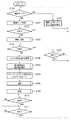
図2は、本発明の第1の実施形態における撮像装置の動作を示すフローチャートである。図2において、カメラ本体100の電源スイッチ118がONされて撮像装置が動作状態となると、モードダイアルスイッチ60の状態を確認して、撮影モードが選択されているかどうかを判断する(ステップS100)。撮影モード以外のモードが選択されていれば、ステップS101に進んで選択されているモードに対応した処理を実行してステップS100に戻る。撮影モードが選択されていればステップS101に進む。ステップS101では、レリーズボタン(不図示)が半押しされ、レリーズスイッチSW1(62)がONされたか否かを判別する(ステップS101)。レリーズスイッチSW1(62)がONされていない場合は、ONされるまでこの判別動作を繰り返し実行する。 FIG. 2 is a flowchart showing the operation of the imaging apparatus according to the first embodiment of the present invention. In FIG. 2, when the
レリーズスイッチSW1(62)がONされると、システム制御回路50は、測光処理を行って絞り値及びシャッタースピードを決定し、測距処理を行って撮像光学系310の焦点を被写体に合わせる(ステップS103)。測光の結果、必要であればストロボ・フラグをセットし、ストロボの設定も行う。このステップS103で行う測距・測光処理の詳細について、図3を参照して説明する。 When the release switch SW1 (62) is turned on, the
図3は、図2のステップS103における測距・測光処理の詳細なフローチャートを示す。システム制御回路50は、撮像素子14から電荷信号を読み出し、A/D変換器16を介して画像処理回路20に画像データを逐次読み込む(ステップS201)。 FIG. 3 shows a detailed flowchart of the distance measurement / photometry process in step S103 of FIG. The
そして、測光部44により画面内を複数エリアに分割して定常光下での被写体輝度を測定する。露出(AE)が適正ではないと判断したならば(ステップS202でNO)、被写体輝度が適正レベルとなるようにシャッタースピードや絞り値を変更するAE制御を行う(ステップS203)。そしてステップS204に進み、システム制御回路50は、AE制御で得られた測定データを用いてストロボによる調光が必要か否かを判断する。ストロボによる調光が必要ならば(ステップS204でYES)ストロボ・フラグをセットし、ストロボ70を充電する(ステップS205)。 Then, the
露出(AE)が適正と判断したならば(ステップS202でYES)、シャッタースピード及び絞り値(測光データ)を不揮発性メモリ56に記憶する。 If it is determined that the exposure (AE) is appropriate (YES in step S202), the shutter speed and aperture value (photometric data) are stored in the nonvolatile memory 56.
次に、合焦と判断されるまで(ステップS206でNOの間)、ステップS207においてAF制御を行う。ステップS207では、システム制御回路50は、位相差検出方式による焦点検出動作を行う。焦点検出を行うポイントである焦点検出ポイントが複数ある場合には、撮影者が任意にいずれかの焦点検出ポイントを選択するようにしても、近点優先を基本の考え方とした自動選択方式により選択するようにしてもよい。ここでは、測距部42から得られるAF信号が、選択された焦点検出ポイントで合焦を示す値となるように、インターフェース120および320、コネクタ122および322を介してフォーカス制御部342を制御する。このようにして、撮像光学系310のフォーカスレンズを駆動することによってAF制御を行う。 Next, AF control is performed in step S207 until it is determined that focus is achieved (NO in step S206). In step S207, the
測距(AF)の結果、合焦と判断したならば(ステップS206でYES)、測定データ及び/或いは設定パラメータを不揮発性メモリ56に記憶に記憶し、測距・測光処理ルーチン(ステップS103)を終了する。 If it is determined that the subject is in focus as a result of the distance measurement (AF) (YES in step S206), the measurement data and / or setting parameters are stored in the nonvolatile memory 56, and the distance measurement / photometry processing routine (step S103) Exit.
測距・測光処理が終了すると、ステップS104に進み、レリーズボタン(不図示)が全押しされたか否か、即ち、レリーズスイッチSW2(64)がONされたか否かを判定する。そしてレリーズスイッチSW2(64)がONされていない場合は、ステップS105に進み、レリーズスイッチSW1(62)がONされているかどうかを判定する。ONの場合には、ステップS104に戻ってレリーズスイッチSW2(64)の判定を繰り返し、OFFの場合には、ステップS100に戻る。レリーズスイッチSW2(64)がONされると、ステップS106に進む。 When the distance measurement / photometry process ends, the process proceeds to step S104, and it is determined whether or not a release button (not shown) is fully pressed, that is, whether or not the release switch SW2 (64) is turned on. If the release switch SW2 (64) is not turned on, the process proceeds to step S105 to determine whether or not the release switch SW1 (62) is turned on. If it is ON, the process returns to step S104 to repeat the determination of the release switch SW2 (64). If it is OFF, the process returns to step S100. When the release switch SW2 (64) is turned on, the process proceeds to step S106.
ステップS106では、ストロボ発光量Vを算出する。ここで、ステップS106で行われるストロボ発光量Vの演算処理について、図4のフローチャートを参照して説明する。 In step S106, the flash emission amount V is calculated. Here, the calculation processing of the strobe light emission amount V performed in step S106 will be described with reference to the flowchart of FIG.
システム制御回路50は、ストロボ制御部76を制御し、予め設定されたプリ発光量となるようにストロボ装置70のキセノン管72をプリ発光させる(ステップS301)。次に、システム制御回路50は、測光部44によりステップS301でプリ発光した場合の被写体輝度を測定する(ステップS302)。 The
そして、不揮発性メモリ56に記憶されている、図2のステップS103で測定した定常光下での被写体輝度と、ステップS302で測定したプリ発光した時の被写体輝度とに基づいて、適正な露出となるストロボ発光量Vを演算する(ステップS303)。なお、ステップS303におけるストロボ発光量Vの演算方法としては、公知の演算方法を用いることができる。 Then, based on the subject brightness under steady light measured in step S103 of FIG. 2 and the subject brightness when pre-emission measured in step S302, stored in the nonvolatile memory 56, appropriate exposure and The flash emission amount V is calculated (step S303). In addition, as a calculation method of the strobe light emission amount V in step S303, a known calculation method can be used.
ステップS303でストロボ発光量Vの演算を終えると図2に戻り、ストロボ装置70における、キセノン管72の発光時間、及び、白色発光ダイオード74の発光強度および発光タイミングを算出する(ステップS107)。ここで、ステップS107で行われる発光時間、発光強度および発光タイミングの取得処理について説明する。 When the calculation of the strobe emission amount V is completed in step S303, the process returns to FIG. 2, and the light emission time of the
図5は、キセノン管72の発光時間と白色発光ダイオード74の発光強度および発光タイミングを求める動作を示すフローチャートであり、図6は本発明の第1の実施形態におけるキセノン管72と白色発光ダイオード74の発光波形を示す図である。ここで図5及び図6を用いて、図2のステップS105におけるキセノン管72の発光時間、及び白色発光ダイオード74の発光量および発光タイミングを求める処理について説明する。 FIG. 5 is a flowchart showing an operation for obtaining the light emission time of the
まず、ステップS401において、システム制御回路50は、キセノン管72の発光量VXeと、発光時間TXe(t5−t0)を求める。なお、発光時間TXeとは、キセノン管72に発光指示を出してから、発光停止指示を出すまでの時間のことを指すものとする。キセノン管72の発光量VXeは、ステップS105で求めたストロボ発光量V以下でなければならない。また、発光時間TXeは、不図示の発光遮断回路の応答遅れやキセノン管72のイオン消滅に係る時間を考慮し、図2のステップS103で決定されたシャッタースピード内にキセノン管72が必ず消灯するように決める必要がある。上述したように、キセノン管72への発光停止を指示してから実際に発光停止に至るまでの時間(以下、「減衰時間Td」と呼ぶ。)は、発光停止指示時の発光量の大きさに関わらずあまり変わらない。従って、減衰時間Tdを予め求めておき、シャッタースピードから減衰時間Tdを差し引けば、確実にキセノン管72をシャッタースピード内に消灯させることができる。First, in step S401, the
従って、キセノン管72の全発光量VXe及び発光時間TXeは、例えば、様々な発光時間に対するキセノン管72の発光量を示すテーブルを予めメモリ52などに記憶しておき、条件に合うものを選択することで求めることができる。つまり、発光量VXeがストロボ発光量V以下であって、且つ、発光時間TXeがシャッタースピードから減衰時間Tdを引いた時間よりも短い組み合わせから選択する。ここで、白色発光ダイオード74により補足可能な発光量となる範囲で選択する必要があり、例えば、最もストロボ発光量に近いものを選択する。なお、テーブルの代わりに、発光時間と発光量の関係を近似した式を記憶しておくようにしても良い。Therefore, the total light emission amount VXe and the light emission time TXe of the
次に、ストロボ発光量Vとキセノン管72の全発光量の差(=V−VXe)を白色発光ダイオード74の発光量VLEDとする(ステップS402)。Next, the difference (= V−VXe ) between the strobe light emission amount V and the total light emission amount of the
次に、白色発光ダイオード74の発光量VLEDと、シャッタースピードとから、白色発光ダイオード74の発光タイミングtLED及び発光強度ILEDを算出する(ステップS403)。白色ダイオード74の発光強度は、図13に示したように発光時間に関係なく一定であると共に、電流によって制御することが可能である。従って、白色発光ダイオード74の発光強度ILED×発光時間TLEDが白色発光ダイオード74の発光量VLEDとなるように、任意に決定することが可能である。例えば、先幕シンクロ、後幕シンクロ、スポーツ撮影モード、通常撮影モード、というように、目的に応じて予め適切な発光時間TLEDを設定しておき、発光強度を決定するようにすることが考えられる。発光タイミングtLEDは、シャッタースピードから発光時間TLEDを差し引くことで求めることができる。Next, the light emission timing tLED and the light emission intensity ILED of the white
上述したようにして、ストロボ装置70のキセノン管72の発光時間TXeおよび白色発光ダイオード74の発光強度ILEDおよび発光タイミングtLEDの算出動作を終えると、図2の処理に戻る。As described above, when the calculation operation of the light emission time TXe of the
そして、ステップS108へ進み、撮影処理を行う。このステップS108で行われる撮影処理について、図7を参照して説明する。 Then, the process proceeds to step S108, and photographing processing is performed. The photographing process performed in step S108 will be described with reference to FIG.
図7は、図2のステップS108における撮影処理の詳細なフローチャートを示す。 FIG. 7 shows a detailed flowchart of the photographing process in step S108 of FIG.
システム制御回路50は、ステップS501において、不揮発性メモリ56に記憶された測光データを読み出す。そして、測光部44により、絞り機能を有するシャッター12を読み出した測光データに対応する絞り値に応じて開放し、ステップS502で撮像素子14の露光を開始する。 In step S501, the
ステップS503で、ストロボ・フラグがセットされているかをチェックしてストロボ70が必要か否かを判断する。必要な場合にはキセノン管72及び白色発光ダイオード74を、ステップS105で取得した発光時間、発光強度、発光タイミングに基づいて発光させる(ステップS504)。ストロボ70が不要な場合には、ストロボ70の発光を行わずに、ステップS505に進む。 In step S503, it is checked whether or not the strobe flag is set to determine whether or not the
システム制御回路50は、測光データに従って撮像素子14の露光終了を待ち(ステップS505)、シャッター12を閉じて(ステップS506)、撮像素子14から電荷信号を読み出す。そして、A/D変換器16、画像処理回路20、メモリ制御回路22を介して、或いはA/D変換器16から直接メモリ制御回路22を介して、メモリ30に撮影画像のデータを書き込む(ステップS507)。 The
一方、ストロボ・フラグがセットされている場合には、上記処理と並行して、システム制御回路50は、以下の処理を行う。まず、ステップS105で算出されたキセノン管72および白色発光ダイオード74の発光量を基に、ストロボホワイトバランス算出回路150によりストロボ装置70から発光されるストロボ光の色温度を算出する(ステップS510)。そして、算出された色温度に応じて、予め設定されたホワイトバランス調整のゲインを色温度補正データ記憶部152に記憶させる(ステップS511)。 On the other hand, when the strobe flag is set, the
そしてホワイトバランス制御回路154は、色温度補正データ記憶部152に記憶されたゲインを基に、撮影した画像の画像データを画像処理回路20がホワイトバランス処理するのに必要なホワイトバランス補正データを算出する(ステップS512)。 The white
ステップS507の後、システム制御回路50は、メモリ制御回路22そして必要に応じて画像処理回路20を用いて、メモリ30に書き込まれた画像データを読み出す。そして、読み出した画像データに対して、必要に応じて垂直加算処理や所定の画素補間処理、色処理等の画像処理を順次行う(ステップS508)。その後、ホワイトバランス補正データと共に、メモリ制御回路22を介して、メモリ30に書き込む(ステップS509)。あるいは、画像処理を施されていないA/D変換器16から出力された画像データを、直接メモリ制御回路22を介してホワイトバランス補正データと共に、画像メモリ24あるいはメモリ30に書き込むようにしても良い。 After step S507, the
システム制御回路50は、メモリ30から画像データを読み出し、メモリ制御回路22を介して画像表示メモリ24に表示画像データの転送を行う(ステップS513)。一連の処理を終えたならば、撮影処理ルーチン(ステップS108)を終了する。 The
撮影処理が終了すると、ステップS109に進んで記録処理を行う。図8は、図2のステップS109における記録処理の詳細なフローチャートを示す。 When the photographing process ends, the process proceeds to step S109 to perform a recording process. FIG. 8 shows a detailed flowchart of the recording process in step S109 of FIG.
まず、ステップS601において、システム制御回路50は、メモリ30から読み出された画像データに対して圧縮・伸長回路32で圧縮処理を行う。そして、インターフェース90或いは94、コネクタ92或いは96を介して、メモリカードやコンパクトフラッシュ(登録商標)カード等の記録媒体200或いは210へ圧縮した画像データの書き込みを行う(ステップS602)。 First, in step S <b> 601, the
記録媒体への書き込みが終わったならば、記録処理ルーチン(ステップS109)を終了する。 When the writing to the recording medium is completed, the recording processing routine (step S109) is terminated.
記録処理が終了すると、システム制御回路50は、レリーズスイッチSW2の状態を判断し、OFFされるまで待機する(ステップS110)。シャッタースイッチSW2が放されると、シャッタースイッチSW1の状態を判断し、OFFされるまで待機する(ステップS111)。シャッタースイッチSW1がOFFされると、システム制御回路50は、一連の撮影動作を終えてステップS100に戻る。 When the recording process is completed, the
以上説明したように、本第1の実施形態に係る撮像装置では、発光量は大きいが微小発光量の制御が難しいキセノン管と、微小発光量の制御は容易であるが発光量が小さい白色発光ダイオードを、適切な全体発光量が得られるように組み合わせて発光させる。これにより、適切なタイミングで過不足無く所望の発光量を得ることが可能になる。 As described above, in the imaging apparatus according to the first embodiment, the xenon tube having a large light emission amount but difficult to control the minute light emission amount, and the white light emission in which the minute light emission amount is easily controlled but the light emission amount is small. The diodes are combined to emit light so that an appropriate total light emission amount can be obtained. Thereby, it is possible to obtain a desired light emission amount at an appropriate timing without excess or deficiency.
<第2の実施形態>
次に、図1に示す構成を有する撮像装置の本発明の第2の実施形態に係る動作について説明する。<Second Embodiment>
Next, the operation of the imaging apparatus having the configuration shown in FIG. 1 according to the second embodiment of the present invention will be described.
図9は、本発明の第2の実施形態における撮像装置の動作を示すフローチャートである。なお、図9において、第1の実施形態で説明した図2に示す処理と同様の処理には同じ参照番号を付し、説明を適宜省略する。 FIG. 9 is a flowchart showing the operation of the imaging apparatus according to the second embodiment of the present invention. In FIG. 9, the same processes as those shown in FIG. 2 described in the first embodiment are denoted by the same reference numerals, and the description thereof is omitted as appropriate.
図9において、撮影モードが選択されると(ステップS100でYES)、ステップS701において、同調モード切り換えスイッチ66により、ストロボ撮影時の同調モードが先幕シンクロモードと後幕シンクロモードの何れに設定されているかを判断する。 In FIG. 9, when the shooting mode is selected (YES in step S100), in step S701, the tuning
その後、レリーズボタン(不図示)が半押しされて、レリーズスイッチSW1(62)がONされると(ステップS102)、ステップS103で測距・測光処理を行い、ステップS104に進む。ステップS104においてレリーズスイッチSW2(64)がONされると、ステップS106でストロボ発光量Vを求める。 Thereafter, when a release button (not shown) is pressed halfway and the release switch SW1 (62) is turned on (step S102), distance measurement / photometry processing is performed in step S103, and the process proceeds to step S104. When the release switch SW2 (64) is turned on in step S104, the flash emission amount V is obtained in step S106.
次に、ステップS702で、ストロボ装置70における、キセノン管72の発光時間と白色発光ダイオード74の発光強度を算出する。 Next, in step S702, the light emission time of the
図10は、ステップS702で行われる本第2の実施形態におけるキセノン管72と白色発光ダイオード74の発光量を決定する動作を示すフローチャートである。 FIG. 10 is a flowchart showing an operation of determining the light emission amounts of the
まず、システム制御回路50は、被写体像の残像を写すのに必要な白色ダイオード74の発光強度ILEDを求める(ステップS801)。この際、図9のステップS103で測定した定常光下での被写体輝度と、ステップS104でストロボ発光量Vを求めるために測定したプリ発光した時の被写体輝度とに基づいて求める。例えば、定常光下での様々な被写体輝度と、プリ発光した時の様々な被写体輝度とに対する、被写体像の残像を写すのに必要な発光強度を予めテーブルとして記憶しておき、条件に合うものを選択することで求めることができる。また、対応する被写体輝度がテーブルに無い場合には、補間処理等を行って発光強度を求めればよい。First, the
次に、ステップS802において、キセノン管72の発光時間TLEDを求める。そのために、システム制御回路50は、まず、キセノン管72の発光量VLEDを求める。キセノン管72の発光量VXeは、白色発光ダイオード74の発光量VLEDとキセノン管72の発光量VXeの和がストロボ装置70のストロボ発光量Vと等しい。ここでは、ストロボ発光量Vと、白色発光ダイオードの発光強度ILED及びシャッタースピード(露光時間)が決まっているので、発光強度ILED×シャッタースピードにより求められる白色発光ダイオードの発光量VLEDをストロボ発光量Vから減算する。更に、求めたキセノン管72の発光量VXeから、当該発光量を得るために必要な発光時間TXeを求める。発光時間TXeは、例えば、上記第1の実施形態において説明した図5のステップS401で用いたものと同様のテーブルまたはその近似式を用いて求めることができる。なお、対応する発光量がテーブルに無い場合には、補間処理等を行って発光時間を求めればよい。Next, in step S802, the light emission time TLED of the
上述したようにしてストロボ装置70の白色発光ダイオード74の発光強度ILED及びキセノン管72の発光時間TXeを決定する動作を終えると、図9の処理に戻る。When the operation of determining the light emission intensity ILED of the white
ステップS703へ進み、システム制御回路50は不揮発性メモリ56からステップS103で決定したシャッタースピードを読み込む。更に、システム制御回路50内の時間カウントの基準となる計時手段であるタイマー(不図示)をスタートさせる。 In step S703, the
次に、ステップS704において、撮影処理を行う。図11は、本第2の実施形態における撮影処理の詳細なフローチャートを示す。 Next, in step S704, shooting processing is performed. FIG. 11 shows a detailed flowchart of the photographing process in the second embodiment.
始めに、システム制御回路50は、ストロボ・フラグがセットされているかをチェックする(ステップS900)。ストロボ・フラグがセットされていない場合には、ステップS920に進んで、不揮発性メモリ56に記憶された測光データを読み出す。そして、測光部44により、絞り機能を有するシャッター12を読み出した測光データに対応する絞り値に応じて開放し、ステップS921で撮像素子14の露光を開始する。 First, the
次に、ステップS922では、システム制御回路50内の不図示のタイマーによってカウントされている時間tが次式(1)を満たす値に達したか否かを判定する。
t=Ts+tr …(1)Next, in step S922, it is determined whether or not the time t counted by a timer (not shown) in the
t = Ts + tr (1)
なお、Tsは、図9のステップS703で読み込んだシャッタースピード、trはレリーズタイムラグである。Note that Ts is the shutter speed read in step S703 in FIG. 9, and tr is the release time lag.
ステップS922で時間tが上記式(1)を満たす値に達するまで待ち、達するとステップS923に進み、システム制御回路50は、シャッター制御部40を介してシャッター12を閉じる。 In step S922, the process waits until the time t reaches a value satisfying the above expression (1), and when it reaches, the process proceeds to step S923, and the
一方、ストロボ・フラグがセットされている場合には、ステップS901に進んで、同調モード切り替えスイッチ66が先幕シンクロモードと後幕シンクロモードのどちらを示しているかを判別する。先幕シンクロモードであった場合はステップS902へ、後幕シンクロモードであった場合はステップS910へ進む。 On the other hand, if the strobe flag is set, the process proceeds to step S901 to determine whether the tuning
ステップS902では、システム制御回路50内の不図示のタイマーによってカウントされている時間tが、レリーズタイムラグtrに達するまで待ち、時間tがレリーズタイムラグtrに達すると、ステップS903に進む。 In step S902, the process waits until the time t counted by a timer (not shown) in the
時間tがレリーズタイムラグtrに達すると、システム制御回路50は、シャッター制御部40を介してシャッター12の先幕を走行させる。この動作と共に、ストロボ制御回路76を介してストロボ装置70内の白色発光ダイオード74に対して、図9のステップS702で求めた発光強度ILEDでの発光を開始させる(ステップS903)。When the time t reaches the release time lag tr, the
ステップS904では、シンクロ接点スイッチ(X接点スイッチ)41がONになったか否か、即ち、先幕が全開したかどうかを判定し、ONになるとステップS905に進む。ステップS905では、システム制御回路50は、ストロボ制御回路76を介してストロボ装置70内のキセノン管72を、図9のステップS702で決定した発光時間TXe、発光させる。In step S904, it is determined whether or not the sync contact switch (X contact switch) 41 is turned on, that is, whether or not the front curtain is fully opened. If it is turned on, the process proceeds to step S905. In step S905, the
一方、ステップS901において、同調モード切り替えスイッチ66が後幕シンクロモードであった場合、ステップS910に進む。そして、システム制御回路50内の不図示のタイマーによってカウントされている時間tが、レリーズタイムラグtrに達するまで待ち、時間tがレリーズタイムラグtrに達すると、ステップS911に進む。 On the other hand, if the tuning
時間tがレリーズタイムラグtrに達すると、システム制御回路50は、シャッター制御部40を介してシャッター12の先幕を走行させる。この動作と共に、ストロボ制御回路76を介してストロボ装置70内の白色発光ダイオード74に対して、図9のステップS702で求めた発光強度ILEDでの発光を開始させる(ステップS911)。When the time t reaches the release time lag tr, the
ステップS912では、システム制御回路50内のタイマー(図示せず)によってカウントされている時間tが、次式(2)を満たす値に達したか否かを判定する。
t=Ts+tr−TXe−Td …(2)In step S912, it is determined whether the time t counted by a timer (not shown) in the
t = Ts + tr−TXe −Td (2)
なお、Tsは、図9のステップS703で読み込んだシャッタースピード、trはステップS910でのレリーズタイムラグ、TXeは図9のステップS702において決定されたキセノン管72の発光時間である。また、Tdは、キセノン管72への発光停止を指示してから、発光遮断回路の応答遅れやキセノン管72のイオン消滅により実際に発光停止に至るまでの時間を示す。Note that Ts is the shutter speed read in step S703 in FIG. 9, tr is the release time lag in step S910, and TXe is the light emission time of the
ステップS912で時間tが上記式(2)を満たす値に達するまで待ち、達すると、ステップS905に進む。 In step S912, the process waits until the time t reaches a value satisfying the above expression (2), and when it reaches, the process proceeds to step S905.
ステップS905では、システム制御回路50が、ストロボ制御回路76を介してストロボ装置70内のキセノン管72を、図9のステップS702で決定したキセノン管発光時間TXe、発光させる。In step S905, the
ステップS906では、システム制御回路50内の不図示のタイマーによってカウントされている時間tが式(1)を満たす値に達したか否かを判定する。
t=Ts+tr …(1)In step S906, it is determined whether the time t counted by a timer (not shown) in the
t = Ts + tr (1)
ステップS906で時間tが上記式(1)を満たす値に達するまで待ち、達するとステップS907に進み、システム制御回路50は、シャッター制御部40を介してシャッター12の後幕を走行させる。 In step S906, the process waits until the time t reaches a value satisfying the above expression (1), and when it reaches, the process proceeds to step S907, and the
シャッター12の後幕が走行を終了すると、システム制御回路50はストロボ制御部76を介してストロボ装置70内の白色発光ダイオード74を消灯させる(ステップS908)。 When the rear curtain of the
また、ストロボ・フラグがセットされている場合には、上記処理と並行して、図7のステップS510〜S512で説明した処理を行い、WB補正データを算出する。 If the strobe flag is set, the processing described in steps S510 to S512 in FIG. 7 is performed in parallel with the above processing to calculate WB correction data.
ステップS507以降の処理は、図7で説明した処理と同様であるため、同じ参照番号を付して説明を省略する。 Since the processing after step S507 is the same as the processing described with reference to FIG. 7, the same reference numerals are assigned and description thereof is omitted.
ここで撮影動作が終了し、図9のステップS704へと戻る。ステップS109〜S111の処理は、図2で説明した処理と同様であるため、同じ参照番号を付して説明を省略する。 Here, the photographing operation ends, and the process returns to step S704 in FIG. Since the processing of steps S109 to S111 is the same as the processing described in FIG. 2, the same reference numerals are assigned and description thereof is omitted.
以上説明したように、本第2の実施形態によれば、上記第1の実施形態と同様の効果に加えて、以下の効果を得ることができる。即ち、被写体輝度が低い場合や周辺光量が少ない場合であっても、露光中は発光ダイオードが発光した状態を継続することによって被写体像の残像を撮影するために必要な光量を得ることができる。また、キセノン管をシンクロタイミングで発光させることによって、撮影者が選択したシンクロモード撮影(先幕シンクロモード、若しくは後幕シンクロモード)に合った撮影を行うことが可能となる。 As described above, according to the second embodiment, in addition to the same effects as in the first embodiment, the following effects can be obtained. That is, even when the subject brightness is low or the amount of peripheral light is small, the light amount necessary for photographing the afterimage of the subject image can be obtained by continuing the light emitting diode during the exposure. In addition, by causing the xenon tube to emit light at the sync timing, it is possible to perform shooting suitable for the sync mode shooting (first curtain sync mode or rear curtain sync mode) selected by the photographer.
なお、上記第1及び第2の実施形態においては、レンズユニット300がカメラ本体100から着脱可能な構成のものを説明したが、カメラ本体100内にレンズを内蔵したものにも本発明を適用可能であることは言うまでもない。 In the first and second embodiments, the
また、上記第1及び第2の実施形態においては、一般的なストロボ装置の発光素子として、キセノン管と白色発光ダイオードを用いる場合について説明したが、本願発明はこれに限るものではない。閃光を発光可能な発光素子と、一定の発光強度の光を持続的に発光可能な発光素子とを組み合わせて用いる場合に、本願発明を適用することが可能である。 In the first and second embodiments, the case where a xenon tube and a white light emitting diode are used as the light emitting element of a general strobe device has been described. However, the present invention is not limited to this. The present invention can be applied to a combination of a light emitting element capable of emitting flash light and a light emitting element capable of continuously emitting light having a constant light emission intensity.
また、上記第1及び第2の実施形態においては、ストロボがカメラ本体100に内蔵されている場合について説明したが、これに限るものではない。上述したように、キセノン管等の閃光を発光可能な発光素子と、白色発光ダイオード等の一定の発光強度の光を持続的に発光可能な発光素子とを用いる外部ストロボ装置を、コネクタ128を介して外付けした場合に本発明を適用可能であることは言うまでもない。 In the first and second embodiments, the case where the strobe is built in the
12:シャッター、14:撮像素子、16:A/D変換器、18:タイミング発生回路、20:画像処理回路、22:メモリ制御回路、24:画像表示メモリ、26:D/A変換器、28:画像表示部、30:メモリ、32:圧縮伸長回路、40:シャッター制御部、41:シンクロ接点スイッチ、42:測距部、44:測光部、48:被写体距離検出部、50:システム制御回路、52:メモリ、54:通知部、56:不揮発性メモリ、60:モードダイアルスイッチ、62:シャッタースイッチSW1、64:シャッタースイッチSW2、66:同調モード切り替えスイッチ、70:ストロボ、72:キセノン管、73:メインコンデンサ、74:白色発光ダイオード、76:ストロボ制御部、80:電源制御部、82:電池残量検出部、84、86:コネクタ、88:電源:90、94:入出力I/F、92、96:コネクタ、98:記録媒体着脱検知部、100:カメラ本体、106:レンズマウント、110:光学ファインダー、112:コネクタ(アンテナ)、116:操作部、120:インターフェース、122:コネクタ、124:レンズ着脱検知部、126:インターフェース、128:コネクタ、130、132:ミラー、134:ストロボ着脱検出部、150:ホワイトバランス制御回路、152:色温度補正データ記憶部、154:ホワイトバランス制御回路、200、210:記録媒体、202、212:記録部、204、214:インターフェース、206、216:コネクタ、300:レンズユニット、306:レンズマウント、310:撮像光学系、312:絞り、320:インターフェース、322:コネクタ、340:絞り制御部、342:フォーカス制御部、344:ズーム制御部、350:レンズシステム制御回路12: Shutter, 14: Image sensor, 16: A / D converter, 18: Timing generation circuit, 20: Image processing circuit, 22: Memory control circuit, 24: Image display memory, 26: D / A converter, 28 : Image display unit, 30: Memory, 32: Compression / decompression circuit, 40: Shutter control unit, 41: Synchro contact switch, 42: Distance measurement unit, 44: Photometry unit, 48: Subject distance detection unit, 50: System control circuit 52: Memory, 54: Notification unit, 56: Non-volatile memory, 60: Mode dial switch, 62: Shutter switch SW1, 64: Shutter switch SW2, 66: Tuning mode switch, 70: Strobe, 72: Xenon tube, 73: Main capacitor, 74: White light emitting diode, 76: Strobe control unit, 80: Power supply control unit, 82: Battery remaining amount detection unit 84, 86: Connector, 88: Power supply: 90, 94: Input / output I / F, 92, 96: Connector, 98: Recording medium attachment / detachment detection unit, 100: Camera body, 106: Lens mount, 110: Optical viewfinder, 112 : Connector (antenna), 116: operation unit, 120: interface, 122: connector, 124: lens attachment / detachment detection unit, 126: interface, 128: connector, 130, 132: mirror, 134: strobe attachment / detachment detection unit, 150: white Balance control circuit, 152: Color temperature correction data storage unit, 154: White balance control circuit, 200, 210: Recording medium, 202, 212: Recording unit, 204, 214: Interface, 206, 216: Connector, 300: Lens unit 306: Lens mount 310: Imaging optics , 312: diaphragm, 320: Interface, 322: connector, 340: aperture control unit, 342: a focus control unit, 344: zoom control unit, 350: lens system control circuit
Claims (14)
Translated fromJapanese前記第1の発光手段と、前記第2の発光手段の発光量及び発光タイミングを制御する制御手段と
を有することを特徴とする撮像装置。Strobe means having first light emitting means for emitting flash light and second light emitting means for continuously emitting light of constant intensity;
An imaging apparatus comprising: the first light emitting unit; and a control unit that controls a light emission amount and a light emission timing of the second light emitting unit.
前記制御手段は、前記第1の発光手段の発光量と、前記第2の発光手段の発光量との合計が、前記ストロボ手段の発光量になると共に、前記露光時間内に前記第1の発光手段の発光が終了するように、前記第1の発光手段及び前記第2の発光手段の発光量及び発光タイミングを制御することを特徴とする請求項1に記載の撮像装置。Further comprising an acquisition means for acquiring the light emission amount of the strobe means necessary for shooting and the exposure time according to the subject brightness,
The control means adds the light emission amount of the first light emission means and the light emission quantity of the second light emission means to the light emission amount of the strobe means, and the first light emission within the exposure time. The imaging apparatus according to claim 1, wherein a light emission amount and a light emission timing of the first light emitting unit and the second light emitting unit are controlled so that the light emission of the unit is terminated.
前記制御手段は、前記発光強度決定手段により決定した発光強度で得られる前記第2の発光手段の発光量が、前記ストロボ手段の発光量に満たない場合に、不足分の発光量を前記第1の発光手段の発光量として決定することを特徴とする請求項2に記載の撮像装置。Further comprising emission intensity determining means for determining the emission intensity of the second light emitting means necessary for leaving an afterimage of the subject in the captured image according to the subject brightness,
The control means sets the insufficient light emission amount when the light emission amount of the second light emitting means obtained with the light emission intensity determined by the light emission intensity determination means is less than the light emission amount of the strobe means. The imaging apparatus according to claim 2, wherein the imaging device determines the amount of light emitted by the light emitting means.
前記制御手段は、前記選択手段による選択結果に応じて、前記第1の発光手段の発光タイミングを制御することを特徴とする請求項2に記載の撮像装置。A selection means for selecting either the first curtain sync mode or the second curtain sync mode;
The imaging apparatus according to claim 2, wherein the control unit controls a light emission timing of the first light emitting unit according to a selection result by the selection unit.
一定強度の光を持続的に発光する第2の発光手段と、
前記第1の発光手段と、前記第2の発光手段の発光量及び発光タイミングを制御する制御手段と
を有することを特徴とするストロボ装置。A first light emitting means for emitting a flash;
A second light emitting means for continuously emitting light of constant intensity;
A strobe device comprising: the first light emitting means; and a control means for controlling a light emission amount and a light emission timing of the second light emitting means.
被写体輝度に応じて、撮影に必要な前記ストロボ装置の発光量及び露光時間を取得する取得工程と、
前記第1の発光手段の発光量と、前記第2の発光手段の発光量との合計が、前記取得手段により取得した前記ストロボ手段の発光量になると共に、前記露光時間内に前記第1の発光手段の発光が終了するように、前記第1の発光手段及び前記第2の発光手段の発光量及び発光タイミングを決定する発光時間決定工程と、
前記決定した発光量及び発光タイミングに基づいて、前記第1の発光手段及び前記第2の発光手段を制御する制御工程と
を有することを特徴とする制御方法。A control method of a strobe device used in cooperation with an imaging device, comprising: a first light emitting unit that emits flash light; and a second light emitting unit that continuously emits light having a constant light emission intensity.
An acquisition step of acquiring a light emission amount and an exposure time of the strobe device necessary for shooting according to the subject brightness;
The sum of the light emission amount of the first light emission means and the light emission amount of the second light emission means becomes the light emission amount of the strobe means acquired by the acquisition means, and the first light emission means within the exposure time. A light emission time determining step of determining light emission amounts and light emission timings of the first light emitting means and the second light emitting means so that the light emission of the light emitting means is terminated;
And a control step of controlling the first light emitting means and the second light emitting means based on the determined light emission amount and light emission timing.
前記第1の発光手段の発光量を決定する工程と、
当該決定した発光量が前記ストロボ手段の発光量に満たない場合に、不足分の発光量を前記第2の発光手段の発光量として決定する工程と
を有することを特徴とする請求項11に記載の制御方法。The control step includes
Determining the amount of light emitted by the first light emitting means;
The step of determining when the determined light emission amount is less than the light emission amount of the strobe unit as a light emission amount of the second light emission unit. Control method.
前記制御工程では、前記発光強度決定工程で決定した発光強度で得られる前記第2の発光手段の発光量が、前記ストロボ手段の発光量に満たない場合に、不足分の発光量を前記第1の発光手段の発光量として決定することを特徴とする請求項11に記載の制御方法。A light emission intensity determining step of determining the light emission intensity of the second light emitting means necessary to leave an afterimage of the subject in the captured image according to the subject brightness;
In the control step, when the light emission amount of the second light emitting means obtained with the light emission intensity determined in the light emission intensity determination step is less than the light emission amount of the strobe means, the insufficient light emission amount is set to the first light emission amount. The control method according to claim 11, wherein the light emission amount of the light emitting means is determined.
前記制御工程では、前記選択工程における選択結果に応じて、前記第1の発光手段の発光タイミングを制御することを特徴とする請求項11に記載の制御方法。A selection step for selecting either the first curtain sync mode or the second curtain sync mode;
The control method according to claim 11, wherein in the control step, a light emission timing of the first light emitting unit is controlled according to a selection result in the selection step.
Priority Applications (1)
| Application Number | Priority Date | Filing Date | Title |
|---|---|---|---|
| JP2005380162AJP2007178925A (en) | 2005-12-28 | 2005-12-28 | Imaging device, strobe device, and control method of strobe device |
Applications Claiming Priority (1)
| Application Number | Priority Date | Filing Date | Title |
|---|---|---|---|
| JP2005380162AJP2007178925A (en) | 2005-12-28 | 2005-12-28 | Imaging device, strobe device, and control method of strobe device |
Publications (1)
| Publication Number | Publication Date |
|---|---|
| JP2007178925Atrue JP2007178925A (en) | 2007-07-12 |
Family
ID=38304143
Family Applications (1)
| Application Number | Title | Priority Date | Filing Date |
|---|---|---|---|
| JP2005380162AWithdrawnJP2007178925A (en) | 2005-12-28 | 2005-12-28 | Imaging device, strobe device, and control method of strobe device |
Country Status (1)
| Country | Link |
|---|---|
| JP (1) | JP2007178925A (en) |
Cited By (3)
| Publication number | Priority date | Publication date | Assignee | Title |
|---|---|---|---|---|
| JP2009265269A (en)* | 2008-04-23 | 2009-11-12 | Nikon Corp | Illuminator for photography and photographic device |
| JP2009265112A (en)* | 2008-04-02 | 2009-11-12 | Casio Hitachi Mobile Communications Co Ltd | Imaging apparatus and program |
| JP2014199458A (en)* | 2009-02-09 | 2014-10-23 | 日本電気株式会社 | Portable terminal with camera function, flashlight control method and flashlight control program |
- 2005
- 2005-12-28JPJP2005380162Apatent/JP2007178925A/ennot_activeWithdrawn
Cited By (3)
| Publication number | Priority date | Publication date | Assignee | Title |
|---|---|---|---|---|
| JP2009265112A (en)* | 2008-04-02 | 2009-11-12 | Casio Hitachi Mobile Communications Co Ltd | Imaging apparatus and program |
| JP2009265269A (en)* | 2008-04-23 | 2009-11-12 | Nikon Corp | Illuminator for photography and photographic device |
| JP2014199458A (en)* | 2009-02-09 | 2014-10-23 | 日本電気株式会社 | Portable terminal with camera function, flashlight control method and flashlight control program |
Similar Documents
| Publication | Publication Date | Title |
|---|---|---|
| JP4989385B2 (en) | Imaging apparatus, control method thereof, and program | |
| JP4615458B2 (en) | Exposure control method and imaging apparatus | |
| JP2005184508A (en) | Imaging apparatus and control method thereof | |
| JP2007028211A (en) | Imaging apparatus and control method thereof | |
| US8531586B2 (en) | Image pickup apparatus and storage medium including focus lens control | |
| US8045015B2 (en) | Image pickup apparatus, white balance control method thereof, and storage medium | |
| JP2005045552A (en) | Imaging apparatus and method | |
| US20040032490A1 (en) | Image sensing apparatus, image sensing method, program, and storage medium | |
| JP5311922B2 (en) | Imaging apparatus and control method thereof | |
| JP2006119264A (en) | Photographing equipment | |
| JP4719371B2 (en) | Imaging apparatus and control method thereof | |
| JP2005292740A (en) | Electronic camera | |
| JP4750616B2 (en) | Imaging apparatus and control method thereof | |
| JP2007178925A (en) | Imaging device, strobe device, and control method of strobe device | |
| JP2000115629A (en) | Imaging device and exposure control method | |
| JP4262022B2 (en) | Imaging device | |
| JP2006343646A (en) | Imaging device and flash device | |
| JP2012247708A (en) | Imaging device | |
| JP6611566B2 (en) | IMAGING DEVICE, IMAGING DEVICE CONTROL METHOD, AND PROGRAM | |
| JP2005176062A (en) | Imaging apparatus and imaging method | |
| JP2009302778A (en) | Image capturing apparatus and control method thereof | |
| JP4682104B2 (en) | Imaging device | |
| JP2008270987A (en) | Imaging apparatus and control method thereof | |
| JP5137343B2 (en) | Imaging apparatus and imaging method | |
| JP2006270426A (en) | IMAGING DEVICE, ITS CONTROL METHOD, AND COMPUTER PROGRAM |
Legal Events
| Date | Code | Title | Description |
|---|---|---|---|
| A300 | Application deemed to be withdrawn because no request for examination was validly filed | Free format text:JAPANESE INTERMEDIATE CODE: A300 Effective date:20090303 |