JP2007177767A - Hold-sealing material for exhaust gas-treating body, exhaust gas-treating device and method for manufacturing hold-sealing material - Google Patents
Hold-sealing material for exhaust gas-treating body, exhaust gas-treating device and method for manufacturing hold-sealing materialDownload PDFInfo
- Publication number
- JP2007177767A JP2007177767AJP2005379936AJP2005379936AJP2007177767AJP 2007177767 AJP2007177767 AJP 2007177767AJP 2005379936 AJP2005379936 AJP 2005379936AJP 2005379936 AJP2005379936 AJP 2005379936AJP 2007177767 AJP2007177767 AJP 2007177767A
- Authority
- JP
- Japan
- Prior art keywords
- exhaust gas
- sealing material
- holding sealing
- gas treating
- treating body
- Prior art date
- Legal status (The legal status is an assumption and is not a legal conclusion. Google has not performed a legal analysis and makes no representation as to the accuracy of the status listed.)
- Pending
Links
Images


Classifications
- F—MECHANICAL ENGINEERING; LIGHTING; HEATING; WEAPONS; BLASTING
- F01—MACHINES OR ENGINES IN GENERAL; ENGINE PLANTS IN GENERAL; STEAM ENGINES
- F01N—GAS-FLOW SILENCERS OR EXHAUST APPARATUS FOR MACHINES OR ENGINES IN GENERAL; GAS-FLOW SILENCERS OR EXHAUST APPARATUS FOR INTERNAL-COMBUSTION ENGINES
- F01N3/00—Exhaust or silencing apparatus having means for purifying, rendering innocuous, or otherwise treating exhaust
- F01N3/08—Exhaust or silencing apparatus having means for purifying, rendering innocuous, or otherwise treating exhaust for rendering innocuous
- F01N3/10—Exhaust or silencing apparatus having means for purifying, rendering innocuous, or otherwise treating exhaust for rendering innocuous by thermal or catalytic conversion of noxious components of exhaust
- F01N3/24—Exhaust or silencing apparatus having means for purifying, rendering innocuous, or otherwise treating exhaust for rendering innocuous by thermal or catalytic conversion of noxious components of exhaust characterised by constructional aspects of converting apparatus
- F01N3/28—Construction of catalytic reactors
- F01N3/2839—Arrangements for mounting catalyst support in housing, e.g. with means for compensating thermal expansion or vibration
- F01N3/2853—Arrangements for mounting catalyst support in housing, e.g. with means for compensating thermal expansion or vibration using mats or gaskets between catalyst body and housing
- F—MECHANICAL ENGINEERING; LIGHTING; HEATING; WEAPONS; BLASTING
- F01—MACHINES OR ENGINES IN GENERAL; ENGINE PLANTS IN GENERAL; STEAM ENGINES
- F01N—GAS-FLOW SILENCERS OR EXHAUST APPARATUS FOR MACHINES OR ENGINES IN GENERAL; GAS-FLOW SILENCERS OR EXHAUST APPARATUS FOR INTERNAL-COMBUSTION ENGINES
- F01N3/00—Exhaust or silencing apparatus having means for purifying, rendering innocuous, or otherwise treating exhaust
- F01N3/08—Exhaust or silencing apparatus having means for purifying, rendering innocuous, or otherwise treating exhaust for rendering innocuous
- F01N3/10—Exhaust or silencing apparatus having means for purifying, rendering innocuous, or otherwise treating exhaust for rendering innocuous by thermal or catalytic conversion of noxious components of exhaust
- F01N3/24—Exhaust or silencing apparatus having means for purifying, rendering innocuous, or otherwise treating exhaust for rendering innocuous by thermal or catalytic conversion of noxious components of exhaust characterised by constructional aspects of converting apparatus
- F01N3/28—Construction of catalytic reactors
- B—PERFORMING OPERATIONS; TRANSPORTING
- B01—PHYSICAL OR CHEMICAL PROCESSES OR APPARATUS IN GENERAL
- B01D—SEPARATION
- B01D53/00—Separation of gases or vapours; Recovering vapours of volatile solvents from gases; Chemical or biological purification of waste gases, e.g. engine exhaust gases, smoke, fumes, flue gases, aerosols
- B01D53/34—Chemical or biological purification of waste gases
- B01D53/74—General processes for purification of waste gases; Apparatus or devices specially adapted therefor
- B01D53/86—Catalytic processes
- B—PERFORMING OPERATIONS; TRANSPORTING
- B01—PHYSICAL OR CHEMICAL PROCESSES OR APPARATUS IN GENERAL
- B01J—CHEMICAL OR PHYSICAL PROCESSES, e.g. CATALYSIS OR COLLOID CHEMISTRY; THEIR RELEVANT APPARATUS
- B01J33/00—Protection of catalysts, e.g. by coating
- F—MECHANICAL ENGINEERING; LIGHTING; HEATING; WEAPONS; BLASTING
- F01—MACHINES OR ENGINES IN GENERAL; ENGINE PLANTS IN GENERAL; STEAM ENGINES
- F01N—GAS-FLOW SILENCERS OR EXHAUST APPARATUS FOR MACHINES OR ENGINES IN GENERAL; GAS-FLOW SILENCERS OR EXHAUST APPARATUS FOR INTERNAL-COMBUSTION ENGINES
- F01N2260/00—Exhaust treating devices having provisions not otherwise provided for
- F01N2260/24—Exhaust treating devices having provisions not otherwise provided for for identifying exhaust parts or devices, e.g. by labels, stickers or directly printing
- F—MECHANICAL ENGINEERING; LIGHTING; HEATING; WEAPONS; BLASTING
- F01—MACHINES OR ENGINES IN GENERAL; ENGINE PLANTS IN GENERAL; STEAM ENGINES
- F01N—GAS-FLOW SILENCERS OR EXHAUST APPARATUS FOR MACHINES OR ENGINES IN GENERAL; GAS-FLOW SILENCERS OR EXHAUST APPARATUS FOR INTERNAL-COMBUSTION ENGINES
- F01N2310/00—Selection of sound absorbing or insulating material
- F01N2310/02—Mineral wool, e.g. glass wool, rock wool, asbestos or the like
- F—MECHANICAL ENGINEERING; LIGHTING; HEATING; WEAPONS; BLASTING
- F01—MACHINES OR ENGINES IN GENERAL; ENGINE PLANTS IN GENERAL; STEAM ENGINES
- F01N—GAS-FLOW SILENCERS OR EXHAUST APPARATUS FOR MACHINES OR ENGINES IN GENERAL; GAS-FLOW SILENCERS OR EXHAUST APPARATUS FOR INTERNAL-COMBUSTION ENGINES
- F01N2450/00—Methods or apparatus for fitting, inserting or repairing different elements
- F01N2450/02—Fitting monolithic blocks into the housing
- F—MECHANICAL ENGINEERING; LIGHTING; HEATING; WEAPONS; BLASTING
- F01—MACHINES OR ENGINES IN GENERAL; ENGINE PLANTS IN GENERAL; STEAM ENGINES
- F01N—GAS-FLOW SILENCERS OR EXHAUST APPARATUS FOR MACHINES OR ENGINES IN GENERAL; GAS-FLOW SILENCERS OR EXHAUST APPARATUS FOR INTERNAL-COMBUSTION ENGINES
- F01N2450/00—Methods or apparatus for fitting, inserting or repairing different elements
- F01N2450/28—Methods or apparatus for fitting, inserting or repairing different elements by using adhesive material, e.g. cement
- Y—GENERAL TAGGING OF NEW TECHNOLOGICAL DEVELOPMENTS; GENERAL TAGGING OF CROSS-SECTIONAL TECHNOLOGIES SPANNING OVER SEVERAL SECTIONS OF THE IPC; TECHNICAL SUBJECTS COVERED BY FORMER USPC CROSS-REFERENCE ART COLLECTIONS [XRACs] AND DIGESTS
- Y02—TECHNOLOGIES OR APPLICATIONS FOR MITIGATION OR ADAPTATION AGAINST CLIMATE CHANGE
- Y02A—TECHNOLOGIES FOR ADAPTATION TO CLIMATE CHANGE
- Y02A50/00—TECHNOLOGIES FOR ADAPTATION TO CLIMATE CHANGE in human health protection, e.g. against extreme weather
- Y02A50/20—Air quality improvement or preservation, e.g. vehicle emission control or emission reduction by using catalytic converters
Landscapes
- Chemical & Material Sciences (AREA)
- Engineering & Computer Science (AREA)
- Chemical Kinetics & Catalysis (AREA)
- Health & Medical Sciences (AREA)
- Toxicology (AREA)
- Combustion & Propulsion (AREA)
- Mechanical Engineering (AREA)
- General Engineering & Computer Science (AREA)
- Environmental & Geological Engineering (AREA)
- Analytical Chemistry (AREA)
- Biomedical Technology (AREA)
- General Chemical & Material Sciences (AREA)
- Oil, Petroleum & Natural Gas (AREA)
- Materials Engineering (AREA)
- Organic Chemistry (AREA)
- Exhaust Gas After Treatment (AREA)
- Nonwoven Fabrics (AREA)
- Processes For Solid Components From Exhaust (AREA)
- Exhaust Gas Treatment By Means Of Catalyst (AREA)
- Catalysts (AREA)
- Filtering Materials (AREA)
- Treatment Of Fiber Materials (AREA)
- Filtering Of Dispersed Particles In Gases (AREA)
Abstract
Description
Translated fromJapanese本発明は、表面に識別情報を付与した排気ガス処理体用の保持シール材、該保持シール材から構成される排気ガス処理装置及び該保持シール材の製造方法に関する。 The present invention relates to a holding sealing material for an exhaust gas treating body having identification information provided on the surface, an exhaust gas processing apparatus composed of the holding sealing material, and a method for manufacturing the holding sealing material.
一般に、排気ガス処理装置は車両の排気管に取り付けられ図4に示されるように排気ガスを浄化するための排気ガス処理体21と該排気ガス処理体21を収容する管状のシェル23から構成される。シェル23と排気ガス処理体21の間には排気ガス通過方向の隙間の封鎖、排気ガス処理体の位置ズレ防止及び振動吸収を目的として所定の厚みを有する保持シール材14aが配設されている。従来より、特許文献1に記載されるような保持シール材が知られている。かかる保持シール材は所定の厚み及び反発性を有する無機繊維を含むシート材が略長方形状等の所定の形状に切断されることにより作成される。所定形状に切断された保持シール材は排気ガス処理体に巻き付けられ、排気ガス処理体とともに金属製の管状シェル内に導入される。
ところが、近年、ディーゼルパティキュレートフィルタ(DPF)等の排気ガス浄化フィルタ、排気ガスを浄化するための触媒を担持した触媒担体等、排気ガス処理システムの種類の増加(多様化)により、製造される保持シール材において製品名、製造番号等の識別性が求められていた。 However, in recent years, the exhaust gas purification filter such as a diesel particulate filter (DPF), a catalyst carrier carrying a catalyst for purifying exhaust gas, and the like are manufactured due to an increase (diversification) of types of exhaust gas treatment systems. The holding sealing material has been required to have distinctiveness such as product name and serial number.
本発明は、このような従来技術に存在する問題点に着目してなされたものである。その目的とするところは、無機質繊維を含むシート材からなる保持シール材において、各保持シール材を識別可能な排気ガス処理体用の保持シール材及びその製造方法を提供することにある。 The present invention has been made paying attention to such problems existing in the prior art. An object of the present invention is to provide a holding sealing material for an exhaust gas treating body that can identify each holding sealing material in a holding sealing material made of a sheet material containing inorganic fibers, and a method for manufacturing the same.
上記の目的を達成するために、請求項1記載の発明は、無機繊維を含むシート材から構成されるとともに排気ガス処理体を保持するための排気ガス処理体用の保持シール材であって、前記保持シール材の表面に識別情報が付与されてなることを特徴とする。 In order to achieve the above object, the invention described in claim 1 is a holding sealing material for an exhaust gas treating body that is made of a sheet material containing inorganic fibers and holds the exhaust gas treating body, The surface of the holding sealing material is provided with identification information.
各保持シール材の表面(ひょうめん)(表面(おもてめん、上面)、裏面(底面)、側面等を含む)に識別可能な識別情報を付与したことにより、製品情報、裏表等を間違えるおそれがない。 Product information, back and front, etc. are mistaken by giving identifiable identification information to the surface (hyomen) of each holding seal material (including the front surface (mote noodle, top surface), back surface (bottom surface), side surface, etc.) There is no fear.
請求項2記載の発明は、請求項1記載の排気ガス処理体用の保持シール材において、前記識別情報は、印刷手段により印刷処理が施されることにより付与される。
請求項3記載の発明は、請求項1記載の排気ガス処理体用の保持シール材において、前記識別情報は、該識別情報が記録される部材が前記保持シール材の表面に貼り付けられることにより付与される。According to a second aspect of the present invention, in the holding sealing material for an exhaust gas treating body according to the first aspect, the identification information is given by performing a printing process by a printing unit.
According to a third aspect of the present invention, in the holding sealing material for an exhaust gas treating body according to the first aspect, the identification information is obtained by attaching a member on which the identification information is recorded to the surface of the holding sealing material. Is granted.
請求項4記載の発明は、請求項2記載の排気ガス処理体用の保持シール材において、前記印刷手段は、液体噴霧ヘッドから液体を噴霧させる液体噴霧装置、表面に凹凸形状が施された転写ローラを用いた転動転写装置及び表面に凹凸形状が施された平板を用いた押圧転写装置から選ばれる少なくとも一種である。 According to a fourth aspect of the present invention, there is provided the holding sealing material for an exhaust gas treating body according to the second aspect, wherein the printing means is a liquid spraying device for spraying a liquid from a liquid spraying head, and a transfer having an uneven shape on the surface. It is at least one selected from a rolling transfer device using a roller and a pressure transfer device using a flat plate having a surface with an uneven shape.
請求項5記載の発明は、請求項1から請求項4のいずれか一項記載の排気ガス処理体用の保持シール材において、前記シート材は有機バインダ及び無機バインダの少なくとも一方が添着されている。 According to a fifth aspect of the present invention, in the holding sealing material for an exhaust gas treating body according to any one of the first to fourth aspects, at least one of an organic binder and an inorganic binder is attached to the sheet material. .
請求項6記載の発明は、請求項5記載の排気ガス処理体用の保持シール材において、前記有機バインダは全質量に対し1〜10質量%添着されている。
請求項7記載の発明は、請求項1から請求項6のいずれか一項記載の排気ガス処理体用の保持シール材において、前記無機繊維の平均繊維径は、6μm以上である。According to a sixth aspect of the present invention, in the holding sealing material for an exhaust gas treating body according to the fifth aspect, the organic binder is attached in an amount of 1 to 10% by mass relative to the total mass.
According to a seventh aspect of the present invention, in the holding sealing material for an exhaust gas treating body according to any one of the first to sixth aspects, the average fiber diameter of the inorganic fibers is 6 μm or more.
請求項8記載の発明は、請求項1から請求項7のいずれか一項記載の排気ガス処理体用の保持シール材において、前記シート材はアルミナ−シリカ系ファイバから構成されている。 According to an eighth aspect of the present invention, in the holding sealing material for an exhaust gas treating body according to any one of the first to seventh aspects, the sheet material is made of an alumina-silica fiber.
請求項9記載の発明は、請求項1から請求項8記載のいずれか一項記載の排気ガス処理体用の保持シール材において、前記識別情報は、製品名、製品番号、製造番号、坪量、品種、重量、製品サイズ、適用車種及び裏表の区別から選ばれる少なくとも一つの情報である。 The invention according to claim 9 is the holding sealing material for an exhaust gas treating body according to any one of claims 1 to 8, wherein the identification information includes a product name, a product number, a manufacturing number, and a basis weight. And at least one piece of information selected from the type, weight, product size, applicable vehicle type, and front / back distinction.
請求項10記載の発明は、無機繊維を含むシート材からなる保持シール材が排気ガス処理体の外周面の少なくとも一部に巻き付けられた後、管状のシェル内に配設されることにより構成される排気ガス処理装置において、前記保持シール材の表面に識別情報が付与されている。 The invention as set forth in
請求項11記載の発明は、請求項10記載の排気ガス処理装置において、前記排気ガス処理体は、排気ガスを浄化するための触媒を担持した触媒担体又は排気ガス浄化フィルタである。 An eleventh aspect of the present invention is the exhaust gas processing apparatus according to the tenth aspect, wherein the exhaust gas processing body is a catalyst carrier or an exhaust gas purification filter carrying a catalyst for purifying the exhaust gas.
請求項12記載の発明は、請求項4記載の排気ガス処理体用の保持シール材の製造方法において、前記シート材及び液体噴霧装置を相対移動させる工程、前記液体噴霧ヘッドから液体を噴霧させることにより前記シート材の表面に印刷処理を施す工程からなる。 According to a twelfth aspect of the present invention, in the method for manufacturing a holding sealing material for an exhaust gas treating body according to the fourth aspect, the sheet material and the liquid spraying device are relatively moved, and the liquid spraying head sprays the liquid. The method comprises a step of performing a printing process on the surface of the sheet material.
本発明によれば、無機質繊維を含むシート材からなる保持シール材において、各保持シール材を識別可能な排気ガス処理体用の保持シール材及びその製造方法を提供することができる。 ADVANTAGE OF THE INVENTION According to this invention, in the holding sealing material which consists of a sheet material containing an inorganic fiber, the holding sealing material for exhaust gas processing bodies which can identify each holding sealing material, and its manufacturing method can be provided.
以下、本発明を具体化した排気ガス処理体用の保持シール材の一実施形態を図1〜図4にしたがって説明する。
本実施形態の排気ガス処理体用の保持シール材(以下、「保持シール材」という)14aは、保持シール材用印刷装置(以下、「印刷装置」という)11により表面に印刷処理が施されることにより製造番号等の所定の識別情報が付与される。保持シール材14aは無機質繊維マット14から切り出されることにより作成され、印刷装置11による印刷処理は保持シール材14a切り出し前の無機質繊維マット14に対して行われる。印刷装置11は、印刷対象(ターゲット)である無機質繊維マット14に対し離間状態で液体としてのインク組成物15を粒状又は霧状に噴出することにより印刷を施すインクジェット式印刷装置である液体噴霧装置13を備えてなる。Hereinafter, an embodiment of a holding sealing material for an exhaust gas treating body embodying the present invention will be described with reference to FIGS.
The holding sealing material (hereinafter referred to as “holding sealing material”) 14 a for the exhaust gas treating body of the present embodiment is subjected to a printing process on the surface by a holding sealing material printing device (hereinafter referred to as “printing device”) 11. Thus, predetermined identification information such as a production number is given. The holding sealing
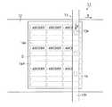
図1に示されるように、印刷装置11により印刷される無機質繊維マット14(ターゲット)は平面形状が略長方形状であり、一定の厚みを有する無機質繊維を含むシート材が一定の幅で切り取られることにより作成される。無機質繊維マット14は一定の反発性を有するように一定の厚みを有するフェルト又は不織布より構成されている。無機質繊維マット14に使用される繊維材料としては例えば、アルミナ系ファイバ、アルミナ−シリカ系ファイバ、シリカ系ファイバ、ガラス系ファイバ等のセラミックファイバが挙げられる。これらの繊維材料のうち耐熱性、高温域における面圧保持性、耐風蝕性の優れたアルミナ−シリカ系ファイバが好ましい。 As shown in FIG. 1, the inorganic fiber mat 14 (target) printed by the
無機質繊維マットの製造方法は特に限定されないが、例えば、0.5〜10mm程度の短繊維を集綿、解繊、積層させることにより、又は短繊維を水に分散させて得た繊維分散液を成形型内に流し込んで加圧・乾燥させることによりマット状の繊維集合体を得ることができる。繊維集合体の厚みは適用される無機質繊維マット14の種類、排気ガス処理体の種類、嵩密度等により適宜設定される。繊維集合体は、好ましくはニードルパンチ(ニードリング)処理を施される。ニードルパンチ処理とは積層シートの厚さを薄くすることにより扱い易くするとともに積層シート間の繊維の係合を強化するために施す処理である。ニードルパンチ処理としては、繊維の積層方向に対して縦方向に一定間隔で定量配向させることが好ましい。これにより複雑に絡み合った繊維が縦方向に配向し、繊維の積層シートの積層間の強化をもたらす。 The manufacturing method of the inorganic fiber mat is not particularly limited. For example, a fiber dispersion obtained by collecting, defibrating, and laminating short fibers of about 0.5 to 10 mm or dispersing the short fibers in water is used. A mat-like fiber aggregate can be obtained by pouring into a mold and pressing and drying. The thickness of the fiber assembly is appropriately set depending on the kind of the
無機質繊維マット14は切断成形前に所定の厚み、反発性及び気密性の付与並びに繊維の飛散防止を目的として、また排気管組み付け時に取り扱い性を向上させることを目的として結合材としてのバインダを用いて含浸処理を施してもよい。バインダとしては無機バインダ及び有機バインダが挙げられるが、インクによる印刷文字の鮮明性の観点より有機バインダが好ましい。無機バインダとしては、モンモリロナイト等の粘土鉱物、水ガラス、合成マイカ、モンモリロナイト、コロイダルアルミナ、コロイダルシリカ等が挙げられる。有機バインダとしてアクリル系樹脂、ポリビニルアルコール等の水溶性樹脂、アクリルゴム、ニトリルゴム、アクリロニトリルーブタジエンゴム(NBR)、スチレンーブタジエンゴム(SBR)等のラテックスが挙げられる。これらのバインダは単独種類で使用してもよく、複数種類を組み合わせて使用してもよい。積層シート中における有機バインダの乾燥後の添着量(添着率)は、好ましくは保持シール材の全重量に対し0質量%を超え且つ12質量%以下であり、より好ましくは0.5〜10質量%、さらに好ましくは1.0〜10質量%である。有機バインダがシート中に配合されないと無機質繊維マット14に対しインクの濡れ性が良すぎるため印刷処理により塗布されたインクが染み込みすぎて印刷文字が不鮮明になるおそれがある。一方、有機バインダの添着率が12質量%を超えると濡れ性が不足するため印刷処理により塗布されたインクが無機質繊維マット14を構成する繊維に十分に添着せずに印刷文字が不鮮明になるおそれがある。 The
有機バインダの繊維シート中における添着量は、加熱による重量の減量(加熱減量率(%))によって表される。例えば、以下の手順により測定される。まず、容器としての磁性皿(A)の重量を測定する。次に、磁性皿にバインダ処理後のサンプル(繊維マット)を入れ、110℃、60分条件下において乾燥処理した後、重量(B)を測定する。次に、サンプル入り磁性皿を600℃、60分条件で加熱処理する。次に、自然冷却後、110℃、60分条件下で乾燥処理した後、重量(B')を測定する。加熱減量率(%)は、初期マット重量(B−A)−加熱後マット重量(B'−A)を重量減少分として、(重量減少分/初期マット重量)×100で表される。 The amount of organic binder attached to the fiber sheet is represented by weight loss due to heating (heating loss rate (%)). For example, it is measured by the following procedure. First, the weight of the magnetic dish (A) as a container is measured. Next, the sample (fiber mat) after the binder treatment is put in a magnetic dish, and after drying at 110 ° C. for 60 minutes, the weight (B) is measured. Next, the sample magnetic dish is heat-treated at 600 ° C. for 60 minutes. Next, after natural cooling, after drying at 110 ° C. for 60 minutes, the weight (B ′) is measured. The weight loss by heating (%) is expressed as (weight reduction / initial mat weight) × 100, where initial mat weight (BA) −mat weight after heating (B′-A) is a weight decrease.
繊維材料の平均繊維径は、保持シール材の種類等に応じ適宜設定されるが、樹脂バインダの添着量が上昇してもインクの添着性が大きく低下することなく鮮明な印字状態を得ることができる太径(6μm以上)が好ましい。平均繊維径が6μm未満であると、インクの添着性が低下することにより印刷文字が不鮮明になるおそれがある。また、保持シール材14aから無機質繊維の飛散を十分に抑制することができないおそれがある。繊維径6μm以上の繊維マットを作成する場合、上記列挙したセラミックファイバのうちアルミナファイバが作製しやすさの観点より好ましく適用される。 The average fiber diameter of the fiber material is appropriately set according to the type of the holding sealing material, etc., but it is possible to obtain a clear print state without greatly decreasing the ink attachment property even if the resin binder attachment amount is increased. A large diameter (6 μm or more) is preferred. If the average fiber diameter is less than 6 μm, there is a risk that the printed characters will become unclear due to a decrease in ink adhesion. Moreover, there exists a possibility that scattering of an inorganic fiber from the
繊維の平均繊維径は、例えば以下のように測定される。まず、繊維材料としての試料を加圧(例えば、20.6MPa)粉砕する。次に、ふるいをかけ試料の均一化を図り、両面テープ等を用いて電子顕微鏡用試料台に付着させる。次に、試料台に付着させた繊維に対し、金、白金、炭素を繊維表面に蒸着させることにより試験体を作製した。次に、試験体を電子顕微鏡を用いて所定倍率(例えば1500倍)下で写真を撮るとともに、写真より繊維径を読みとる(1500倍で測定の場合、0.1μm単位まで測定可能)。次に、測定された繊維径及び本数からなる度数分布表より平均繊維径を求める。 The average fiber diameter of the fiber is measured as follows, for example. First, a sample as a fiber material is pulverized under pressure (for example, 20.6 MPa). Next, the sample is homogenized by sieving and adhered to the electron microscope sample stage using double-sided tape or the like. Next, gold, platinum, and carbon were vapor-deposited on the fiber surface with respect to the fiber adhered to the sample stage, and the test body was produced. Next, while taking a photograph of the specimen under a predetermined magnification (for example, 1500 times) using an electron microscope, the fiber diameter is read from the photograph (in the case of measurement at 1500 times, measurement is possible to the 0.1 μm unit). Next, an average fiber diameter is calculated | required from the frequency distribution table which consists of the measured fiber diameter and the number.
上記のように作成された無機質繊維マット14は図1に示されるように切り取り位置Sで示される位置において、打ち抜き刃等を用いて切断され所定形状の保持シール材14aが作成される。図4に示されるように無機質繊維マット14から切り取られる保持シール材14aは排気ガス処理体21に巻き付けられた際、シェル23の長手方向の隙間を完全に塞ぐために、例えば長手方向の一方の端部に凹部14bが、他方の端部に該凹部14bに嵌合(係合)する凸部14cが形成されている。かかる凹部14bと凸部14cの側面同士が接触することによりシェル23の長手方向の隙間を塞ぐことができる。無機質繊維マット14の切断方法は特に限定されず、帯状の金属板が折り曲げ加工されることにより作成される打抜刃、ハサミ、カッター等が使用される。無機質繊維マットの厚み、硬さ、生産性等を考慮し、炭素鋼により作成される打抜刃が好ましく使用される。一枚の無機質繊維マット14が打抜刃等により切断されることにより、複数の保持シール材14a(図1においては横列12×縦列3=36枚)と外周部においてミミ部14dが切り出される。印刷装置11の無機質繊維マット14上における印刷位置は、各保持シール材の切り出し予定位置に対応して行なわれる。 The
印刷装置11は図1〜3に示されるように左右方向に前進後退可能な搬送台12及び該搬送台12上に対し離間して配され、印刷対象に対してインク組成物15を噴霧する印刷手段としての液体噴霧装置13から構成される。 As shown in FIGS. 1 to 3, the
搬送台12は図示されない駆動手段により所定の移動速度で平行状態で前進後退可能に構成されている。搬送台12の表面の材質は後述する無機質繊維マット14を平行状態で載置することができ、搬送途中において振動等により載置対象が容易に移動することがなく、また傷つけるおそれがなければ特に限定されない。例えば、樹脂板、ゴム板、発泡体、及びそれらに不織布、フェルト等の繊維を積層・被覆させた積層板等を使用することができる。搬送台12を駆動する駆動手段は図示しない制御手段により制御される。無機質繊維マット14の表面上における印刷処理は、制御手段による駆動手段を介した搬送台12の搬送速度と後述する制御手段による液体噴霧装置13からのインク組成物15の噴霧とが連動されることにより行われる。印刷処理時における搬送台12の送り速度は印刷文字の質(例えば、鮮明度)、生産性等を考慮して適宜設定される。 The
液体噴霧装置13は、上述したように印刷対象(ターゲット)である無機質繊維マット14に対し離間状態で液体としてのインク組成物15を粒状又は霧状に噴出することにより印刷を施すインクジェット式印刷装置である。液体噴霧装置13はインク組成物15を無機質繊維マット14に対し噴霧する液体噴霧ヘッド13a及び該液体噴霧ヘッド13aを支持する支持部材13bとから構成されている。支持部材13bは搬送台12上において幅方向に橋渡し状に配されるとともに、図示されない駆動手段により上下方向(搬送方向に対し左右方向)に移動可能に構成されている。液体噴霧ヘッド13aは上述した制御手段が連結され制御手段からの画像・文字信号に応じインク粒を噴出可能に構成されている。無機質繊維マット14に対する印刷処理は制御手段による搬送台12の前進・後退制御及びかかる制御手段によるインク組成物15の噴出制御により行なわれる。印刷処理時における液体噴霧ヘッド13aからのインク粒子の大きさ(ドット)は印刷文字の質(例えば、鮮明度)、生産性等を考慮して適宜設定される。 As described above, the
液体噴霧ヘッド13aはインク組成物15の吐出部が支持部材13bの下面から外部に出る状態で長手方向において等間隔で3つ埋設されている。液体噴霧ヘッド13aからのインク組成物15の吐出法は特に限定されず、無機質繊維マット14の種類、印刷柄等により適宜設定される。例えば、電圧を印加することにより体積が変化する圧電素子(ピエゾ素子)を用いてインク組成物15を噴霧させる方式、インク組成物15を加熱して気泡を作り、気泡の圧力でインク組成物15を噴射する方式等が挙げられる。これらのうち熱を使用しないためインク組成物15の変性が少なく、ヘッドの目詰まりが生じにくい圧電素子を使用する方式が好ましい。 Three liquid spraying heads 13a are embedded at equal intervals in the longitudinal direction in a state in which the discharge portions of the
印刷処理に使用されるインク組成物15は特に限定されず、染料、顔料等を含有する公知のインク組成物が使用される。インク組成物15には、染料、顔料の他溶媒としての水、有機溶媒が含有される。有機溶媒としては、ポリエチレングリコール等のポリアルキレングリコール類、プロピレングリコール等のアルキレングリコール類、グリセリン等のピロリドン類、アルコール類等が挙げられる。染料としては、例えば、直接染料、酸性染料、塩基性染料等の水溶性染料が挙げられる。染料は通常水、有機溶媒等に溶解した状態で使用されるため、沈殿等の不都合が生じにくい。 The
顔料としては、有機顔料と無機顔料が挙げられる。有機顔料としては、例えば、アゾレーキ、縮合アゾ、キレートアゾ等のアゾ系顔料、キナクリドリン、フタロシアニン、アントラキノン、ジオキサジン、チオインジゴ、イソインドリノン、及びキノフタロン等の多環式顔料、ニトロ顔料、ニトロソ顔料、並びにアニリンブラック等が挙げられる。無機顔料としては、例えば、カーボンブラック、二酸化チタン、シリカ、アルミナ、酸化鉄、水酸化鉄及び酸化スズ等が挙げられる。顔料は通常、水、有機溶媒に不溶であり、溶媒中に粒子として分散した状態で存在する。インク組成物15には、その他有機・無機バインダ、分散剤、界面活性剤、pH調整剤、防腐剤、酸化防止剤等を必要に応じて適宜配合することができる。 Examples of the pigment include organic pigments and inorganic pigments. Examples of the organic pigment include azo pigments such as azo lake, condensed azo, and chelate azo, polycyclic pigments such as quinacridrin, phthalocyanine, anthraquinone, dioxazine, thioindigo, isoindolinone, and quinophthalone, nitro pigments, nitroso pigments, and anilines. Black etc. are mentioned. Examples of the inorganic pigment include carbon black, titanium dioxide, silica, alumina, iron oxide, iron hydroxide, and tin oxide. The pigment is usually insoluble in water and an organic solvent, and exists in a state of being dispersed as particles in the solvent. In the
インク組成物15の粘度は20℃において2〜5cSt、好ましくは、3〜4cStである。インク組成物15の粘度が2未満であると無機質繊維マットの内部にインク組成物15が染み込みやすくなるため印刷文字等が不鮮明になるおそれがある。インク組成物15の粘度が5cStより大きいと液体噴霧ヘッド13a内にインク組成物15が詰まりやすくなる。インク組成物15の粘度は主に染料、顔料を溶解する水等の溶媒の量、種類を変えることにより変化させることができる。 The viscosity of the
次に、上記のように構成された保持シール材14aの作用について説明する。
まず、適宜有機バインダ等により処理された無機質繊維マット14が搬送台12上に載置される。次に、無機質繊維マット14は液体噴霧装置13の下(印刷位置)に搬送される。その際、無機質繊維マット14が切り取り位置Sに対応するよう位置合わせされることにより、液体噴霧装置13のインク噴霧位置に切り出し予定の各保持シール材14aが対向する。Next, the operation of the
First, the
次に、無機質繊維マット14の表面上に液体噴霧ヘッド13aからインク組成物15が噴霧され、印刷処理が施される。印刷処理は予め制御手段に入力された文字情報等の識別情報(例えば、図1においてはABCDE)にしたがって行なわれる。制御手段は搬送台12の駆動手段を矢印X方向に稼動させるとともに、液体噴霧ヘッド13aからのインク組成物15の吐出を制御する。それにより無機質繊維マット14上への印字処理が制御される。 Next, the
印刷の順番は例えば図1に示されるように上(搬送方向Xに対し左側)から1番、5番、9番目の列の先頭から搬送台12の稼動方向に印刷処理が施される。一列分(横向き並列状態の3つの保持シール材)の印字処理が終了すると、図2に示されるように液体噴霧ヘッド13aの真下に上(搬送方向Xに対し左側)から2番、6番、10番目の列の先頭が位置するように液体噴霧装置13がY方向に保持シール材一列分移動する。その後同様の印刷処理が繰り返され、無機質繊維マット14上の各保持シール材に印字処理が施される。 For example, as shown in FIG. 1, the printing process is performed from the top (left side with respect to the conveyance direction X) to the operation direction of the conveyance table 12 from the top of the first, fifth, and ninth rows. When the printing process for one row (three holding seal materials in the side-by-side parallel state) is completed, as shown in FIG. 2, the second, sixth, and right from the top (left side with respect to the transport direction X) directly below the
印刷処理が施された無機質繊維マット14は打抜刃等により切り取り位置Sにおいて各保持シール材14aが切り取られる。切り出された保持シール材14aは図4に示されるように排気ガス処理体21の外周面に巻かれ、凹部14b及び凸部14cが嵌合(係合)される。このとき凹部14b及び凸部14cの係合部にシール22等を貼り付けてもよい。保持シール材14aが巻かれた排気ガス処理体21が円筒状の金属製のシェル23内に圧入されることにより排気ガス処理装置が組み付けられる。 Each
本実施形態の排気ガス処理体用の保持シール材14aによれば、以下のような効果を得ることができる。
(1)本実施形態において、無機質繊維マット14は液体噴霧装置13によって印刷処理が施されることにより識別情報が表面に付与される。したがって、保持シール材に対し、製品名、製造番号等の識別性を付与することができる。また、識別情報が片面のみに付与されるため、保持シール材の裏表を間違えるおそれがない。According to the
(1) In this embodiment, the
(2)また、単なる着色樹脂塗料の吹き付け(マーキング)と比較して多くの情報を無機質繊維マット14に付与することができる。
(3)また、ラベル、着色樹脂塗料を使用する必要がなく、ラベル、着色樹脂塗料のシェル内における燃焼を引き起こすことがないため保持シール材の性状を変化させるおそれがない。(2) Further, more information can be imparted to the
(3) Further, there is no need to use a label or a colored resin paint, and there is no possibility of changing the properties of the holding sealing material because it does not cause burning in the shell of the label and the colored resin paint.
(4)本実施形態において、無機質繊維マット14は印刷対象から離間した状態で印刷処理が可能な液体噴霧装置13によって印刷処理が施される。したがって、転写ロール、転写板(スタンプ)等による印刷方法と比較して、保持シール材の長さ、幅等の大きさを考慮する必要がなく、また、印刷文字等を容易に変更することができる。保持シール材の大きさ等を変更したい場合は、駆動手段を介した搬送台12の搬送速度と液体噴霧装置13からのインク組成物15の噴霧を制御する制御手段に入力される印刷文字等の種類・大きさの入力情報を変えることにより容易に印刷文字等を変化させることができる。 (4) In this embodiment, the
(5)また、グラビア印刷、凸版印刷等の転写ローラ、スタンプを用いた印刷方法と比較して、無機質繊維マットが押圧されることがなく、所定の厚み及び反発性を有するシート状の無機質繊維マット14の性状を一層変化させることない。 (5) Sheet-like inorganic fibers having a predetermined thickness and resilience without pressing the inorganic fiber mat as compared with printing methods using transfer rollers and stamps such as gravure printing and letterpress printing The property of the
(6)また、転写ローラ、転写板に無機質繊維が付着し、印刷板の凹部に目詰まりが生じ、印字のかすれ等の問題を引き起こすことがない。つまり、グラビア印刷、凸版印刷等の転写ローラ、スタンプを用いた印刷方法と比較して、鮮明に印字処理を施すことができる。それにより、印刷処理に必要とされるインク組成物の量を減少させることができる。 (6) Further, inorganic fibers adhere to the transfer roller and the transfer plate, and the concave portions of the printing plate are clogged, and problems such as fading of printing do not occur. That is, the printing process can be clearly performed as compared with a printing method using transfer rollers and stamps such as gravure printing and letterpress printing. Thereby, the amount of the ink composition required for the printing process can be reduced.
(7)また、無機質繊維マット14において不織布又はフェルトが使用される場合でも、インク組成物15の粒子は不織布等の内部に垂直方向に侵入するため、印刷処理が施された保持シール材14aの上方から印刷文字を鮮明に確認することができる。 (7) Even when a nonwoven fabric or felt is used in the
(8)本実施形態において、無機質繊維マットに対し、有機バインダにより所定添着率になるよう含浸処理を行った。したがって、無機質繊維マット14に対しより鮮明に印刷処理を施すことができるため例えば製造番号、裏表等の間違えるおそれがない。 (8) In the present embodiment, the inorganic fiber mat was impregnated with an organic binder so as to have a predetermined adhesion rate. Accordingly, since the
(9)本実施形態において、平均繊維径が6μm以上の繊維を使用した。したがって、無機質繊維マット14に対しより鮮明に印刷処理を施すことができる。
(10)本実施形態において、印字作業直前に搬送台12上の無機質繊維マット14は液体噴霧装置13の印刷位置に切り取り位置Sの所定の保持シール材が対向するよう位置合わせされる。したがって、切り出される各保持シール材の表面それぞれに印刷処理が施される。(9) In the present embodiment, fibers having an average fiber diameter of 6 μm or more were used. Therefore, it is possible to print the
(10) In this embodiment, just before the printing operation, the
なお、上記実施形態は以下のように変更してもよい。
・インク組成物15の色は、黒単色でもよく、シアン、マゼンタ、イエロー等のインク組成物を加えカラーインク組成物であってもよい。In addition, you may change the said embodiment as follows.
The color of the
・上記実施形態において、印刷処理後に無機質繊維マット14から各保持シール材14aを切り出した。しかしながら、無機質繊維マット14から各保持シール材14aを切り出した後に印刷装置11により印刷処理を施してもよい。 -In the said embodiment, each holding sealing
・上記実施形態において、搬送台12をX方向へ、液体噴霧装置13をY方向に移動させることにより無機質繊維マット14の表面上に印刷処理を施した。しかしながら、搬送台12を固定し、液体噴霧装置13のみを稼働させることにより印刷処理を施してもよい。また、液体噴霧装置13を固定し、搬送台12のみを稼働させることにより印刷処理を施してもよい。 In the above embodiment, a printing process is performed on the surface of the
・液体噴霧装置13の支持部材13bに取り付けられる液体噴霧ヘッド13aの数は特に限定されず、印刷効率等を考慮し1又は2個以上であればよい。また、無機質繊維マット14上における印刷の順番は印刷効率等を考慮することにより適宜設定される。 The number of
・上記実施形態において、無機質繊維マットから切り取られる保持シール材の枚数は特に限定されず1又は2枚以上であればよい。
・上記実施形態において、保持シール材が使用される排気ガス処理体は、ディーゼルパティキュレートフィルタ(DPF)等のPMを集塵するための排気ガス浄化フィルタ、セラミック等により構成されるとともに排気ガスを浄化するための触媒が担持される触媒担体であってもよい。-In the said embodiment, the number of the holding sealing materials cut off from an inorganic fiber mat is not specifically limited, What is necessary is just 1 or 2 or more.
-In the said embodiment, the exhaust-gas processing body in which a holding sealing material is used is comprised by exhaust-gas purification filters for collecting PM, such as a diesel particulate filter (DPF), ceramics, etc., and exhaust gas. It may be a catalyst carrier on which a catalyst for purification is supported.
・上記実施形態において、液体噴霧ヘッド13aからインク組成物15を噴霧させるインクジェット方式を用いて無機質繊維マット14表面に印刷処理を施した。しかしながら、印刷処理はインクジェット方式に限定されず、グラビア印刷、凸版印刷等の表面に凹凸形状が施された転写ローラを用いた転動転写装置、スタンプ等の表面に凹凸形状が施された平板を用いた押圧転写装置を使用してもよい。転動転写装置、押圧転写装置を用いて印刷処理を施しても、無機質繊維マット14の表面に多くの識別情報を付すことができる。 In the above embodiment, the surface of the
・上記実施形態において、図4に示されるように排気ガス処理体21の外周面全面に保持シール材14aを巻き付けた。しかしながら、保持シール材は排気ガス処理体の外周面の少なくとも一部に巻き付けられる構成であってもよい。 In the above embodiment, the
・上記実施形態において、識別情報を液体噴霧装置13を用いた印刷処理により無機質繊維マット14上に付与した。しかしながら、印刷手段以外の方法によって、識別情報を付与してもよい。印刷手段以外の方法として、識別情報が記録(記載)されるシール部材(ラベル)の貼り付け、識別情報が記録されるICチップの取り付け等により付与してもよい。かかる構成では、印刷装置等を使用することなく貼り付けが可能となるため容易に識別情報を付与することが可能となる。 In the above embodiment, the identification information is provided on the
・上記実施形態において、印刷手段によりシート材上に付与される識別情報は特に限定されず文字情報のみならず数字、記号、バーコード、二次元コードの一種であるQRコード等であってもよい。また、識別情報の内容も特に限定されず製品名、製品番号、製造番号、坪量、品種、重量、製品サイズ、適用車種、裏表の区別等が挙げられる。 In the above embodiment, the identification information provided on the sheet material by the printing means is not particularly limited, and may be not only character information but also a number, a symbol, a barcode, a QR code that is a kind of two-dimensional code, and the like. . Also, the content of the identification information is not particularly limited, and examples include product name, product number, serial number, basis weight, product type, weight, product size, applicable vehicle type, and distinction between front and back.
・上記実施形態において、印刷文字の付与を保持シール材の片面のみに対して行った。しかしながら、印刷位置は特に限定されず、両面、裏面、側面等に対して印刷処理を施してもよい。 -In the said embodiment, the provision of the printing character was performed only to the single side | surface of the holding sealing material. However, the printing position is not particularly limited, and printing processing may be performed on both sides, the back surface, the side surface, and the like.
次に、前記実施形態を更に具体的に説明する。
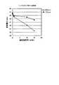
表1に示す試験例1〜8の保持シール材について、下記に示す方法により作成するとともにインク含浸試験及び印刷試験を行った。それらの結果を表1に示す。Next, the embodiment will be described more specifically.
About the holding | maintenance sealing material of Test Examples 1-8 shown in Table 1, while creating by the method shown below, the ink impregnation test and the printing test were done. The results are shown in Table 1.
<アルミナシリカ繊維マットの製造方法>
アルミニウム含有量75g/l,Al/Cl=1.8(原子比)の塩基性塩化アルミニウム水溶液にシリカゾルを配合し、アルミナ繊維の組成がアルミナ:シリカ=72±2:28±2となるように加え、アルミナ繊維の前駆体を形成する。さらに、アルミナ繊維の前駆体にポリビニルアルコールなどの有機重合体を加える。その後、濃縮し紡糸液を調整し、該紡糸液を用いてブローイング法にて紡糸した。紡糸が完了した繊維を平均繊維長が12mmとなるように切断を行いその後、アルミナ繊維前駆体を折り畳んだものを、積み重ねて、アルミナ繊維の積層シートを製造した。このようにして製造されたアルミナ繊維の積層シートに、500箇所/100平方センチメートルでニードルパンチ処理を施す。これを常温から昇温し、最高温度1250℃で連続焼成し目付け量1160g/平方センチメートルのアルミナ繊維の連続積層シートを得た。この時の繊維の平均直径は7.2μm、最小直径は3.2μmであった。裁断された連続積層シートにアクリル系の有機バインダにより含浸処理を施すことにより、表1に示される各試験例の保持シール材を得た。<Method for producing alumina silica fiber mat>
Silica sol is blended in a basic aluminum chloride aqueous solution having an aluminum content of 75 g / l and Al / Cl = 1.8 (atomic ratio) so that the composition of alumina fibers is alumina: silica = 72 ± 2: 28 ± 2. In addition, an alumina fiber precursor is formed. Further, an organic polymer such as polyvinyl alcohol is added to the precursor of alumina fiber. Then, it concentrated and adjusted the spinning solution, and it spun by the blowing method using this spinning solution. Fibers that have been spun were cut so that the average fiber length was 12 mm, and then the alumina fiber precursors folded were stacked to produce a laminated sheet of alumina fibers. The laminated sheet of alumina fibers thus produced is subjected to needle punching at 500 points / 100 square centimeters. This was heated from normal temperature and continuously fired at a maximum temperature of 1250 ° C. to obtain a continuous laminated sheet of alumina fibers having a basis weight of 1160 g / square centimeter. At this time, the average diameter of the fibers was 7.2 μm, and the minimum diameter was 3.2 μm. The cut continuous laminated sheet was impregnated with an acrylic organic binder to obtain the holding sealing material of each test example shown in Table 1.
<インク含浸試験>
上記のように作成した各保持シール材を帯状にカットする。次に、20mlの水溶性インクが入った皿に保持シール材の一端を浸した時を基準として5秒おきに80秒までインクの液面を基準として保持シール材に染み込んだインクの高さを測定した。それらの結果を表1及び図5に示す。<Ink impregnation test>
Each holding sealing material prepared as described above is cut into a strip shape. Next, the height of the ink soaked into the holding sealing material is determined every 5 seconds up to 80 seconds with reference to the liquid level of the ink up to 80 seconds with reference to the time when one end of the holding sealing material is immersed in a dish containing 20 ml of water-soluble ink. It was measured. The results are shown in Table 1 and FIG.
<印刷試験(滲み性)>
各試験例の保持シール材上においてインクジェット式印刷装置を用いて印刷処理を施した場合における印刷文字の滲み性について、5名のパネラーが目視にて印刷文字を観察することにより評価した。印刷文字に滲みが生じていない場合を3点、やや滲みが生している場合を2点、及び滲みが生じている場合を1点とする3段階で採点した。5名のパネラーの採点結果について平均点を算出し、その平均点が2.6点以上の場合を「優れる:◎」、1.6点以上2.5点以下の場合を「良好:○」、及び1.5点以下の場合を「悪い:×」とし、滲み性試験の評価結果とした。それらの評価結果を表1に示す。<Print test (bleedability)>
About the bleeding property of the printed character at the time of performing a printing process using the inkjet-type printing apparatus on the holding | maintenance sealing material of each test example, five panelists evaluated by visually observing the printed character. Scoring was done in three stages, with 3 points when no blurring occurred on printed characters, 2 points when blurring occurred, and 1 point when blurring occurred. The average score is calculated for the scoring results of five panelists. The score is “Excellent: ◎” when the average score is 2.6 or higher, and “Good: ○” when the average score is 1.6 or higher and 2.5 or lower. In addition, the case of 1.5 points or less was evaluated as “bad: x”, and the evaluation result of the bleeding test was used. The evaluation results are shown in Table 1.
<印刷試験(添着性)>
各試験例の保持シール材上においてインクジェット式印刷装置を用いて印刷処理を施した場合におけるインクの繊維への添着性について、5名のパネラーが目視にて印刷文字を観察することにより評価した。インクが十分に繊維に添着している場合を3点、やや添着性が悪い場合を2点、及びインクが十分に繊維に添着していない場合を1点とする3段階で採点した。5名のパネラーの採点結果について平均点を算出し、その平均点が2.6点以上の場合を「優れる:◎」、1.6点以上2.5点以下の場合を「良好:○」、及び1.5点以下の場合を「悪い:×」とし、添着性試験の評価結果とした。それらの評価結果を表1に示す。<Print test (attachment)>
Five panelists evaluated the attachment property of the ink to the fiber when the printing treatment was performed on the holding sealing material of each test example using an ink jet printing apparatus by visually observing the printed characters. The scoring was made in three stages: 3 points when the ink was sufficiently attached to the fiber, 2 points when the ink was slightly poorly attached, and 1 point when the ink was not sufficiently attached to the fiber. The average score is calculated for the scoring results of five panelists. The score is “Excellent: ◎” when the average score is 2.6 or higher, and “Good: ○” when the average score is 1.6 or higher and 2.5 or lower. In addition, the case of 1.5 points or less was evaluated as “bad: ×”, and the evaluation result of the adhesion test. The evaluation results are shown in Table 1.

次に、上記実施形態及び別例から把握できる技術的思想について、それらの効果とともに以下に追記する。
(a)シート状の無機質繊維マットから構成される排気ガス処理体の保持シール材の表面に印刷手段を用いて印刷するための保持シール材用印刷装置において、前記印刷手段は、液体噴霧ヘッドから液体を噴霧させる液体噴霧装置である保持シール材用印刷装置。Next, technical ideas that can be grasped from the above-described embodiment and other examples will be described below together with their effects.
(A) In the holding sealing material printing apparatus for printing on the surface of the holding sealing material of the exhaust gas treating body composed of the sheet-like inorganic fiber mat by using the printing means, the printing means includes a liquid spray head. A printing apparatus for holding sealing material, which is a liquid spraying apparatus for spraying liquid.
(b)複数列に配列される保持シール材が切り取られる無機質繊維マットにおいて、印刷処理は各列毎に行われる保持シール材用印刷装置。従って、この(a)に記載の発明によれば、無機質繊維マットから切り取られる保持シール材の数が増減しても、液体(インク組成物)が噴霧される液体噴霧ヘッドをそれに合わせ複数配設する必要はない。 (B) In the inorganic fiber mat from which the holding sealing material arranged in a plurality of rows is cut, the printing processing for the holding sealing material is performed for each row. Therefore, according to the invention described in (a), even if the number of holding sealing materials cut from the inorganic fiber mat is increased or decreased, a plurality of liquid spraying heads for spraying liquid (ink composition) are arranged accordingly. do not have to.
11…保持シール材用印刷装置、13…印刷手段としての液体噴霧装置、13a…液体噴霧ヘッド、14…無機質繊維マット、14a…保持シール材、15…インク組成物、21…排気ガス処理体、23…シェル。 DESCRIPTION OF
Claims (12)
Translated fromJapanese前記保持シール材の表面に識別情報が付与されてなることを特徴とする排気ガス処理体用の保持シール材。A holding sealing material for an exhaust gas treating body, which is composed of a sheet material containing inorganic fibers and holds the exhaust gas treating body,
A holding sealing material for an exhaust gas treating body, characterized in that identification information is given to the surface of the holding sealing material.
前記シート材及び液体噴霧装置を相対移動させる工程、前記液体噴霧ヘッドから液体を噴霧させることにより前記シート材の表面に印刷処理を施す工程からなる排気ガス処理体用の保持シール材の製造方法。In the manufacturing method of the holding sealing material for exhaust gas treating bodies according to claim 4,
A method for producing a holding sealing material for an exhaust gas treating body, comprising: a step of relatively moving the sheet material and a liquid spraying device; and a step of performing a printing process on the surface of the sheet material by spraying a liquid from the liquid spraying head.
Priority Applications (13)
| Application Number | Priority Date | Filing Date | Title |
|---|---|---|---|
| JP2005379936AJP2007177767A (en) | 2005-12-28 | 2005-12-28 | Hold-sealing material for exhaust gas-treating body, exhaust gas-treating device and method for manufacturing hold-sealing material |
| AT06025959TATE407286T1 (en) | 2005-12-28 | 2006-12-14 | HOLDING AND SEALING ELEMENT FOR AN EXHAUST GAS TREATMENT BODY AND METHOD FOR PRODUCING THE HOLDING AND SEALING ELEMENT |
| EP10183414.1AEP2267283B1 (en) | 2005-12-28 | 2006-12-14 | Method for manufacturing a holding seal member |
| DE602006002586TDE602006002586D1 (en) | 2005-12-28 | 2006-12-14 | Holding and sealing element for an exhaust gas purification body and method for producing the holding and sealing element |
| EP08001389.9AEP1908935B1 (en) | 2005-12-28 | 2006-12-14 | Method for manufacturing a holding seal member for exhaust gas purifying body |
| EP15171369.0AEP2933454B1 (en) | 2005-12-28 | 2006-12-14 | Method for manufacturing holding seal member for exhaust gas purifying body |
| EP06025959AEP1803908B1 (en) | 2005-12-28 | 2006-12-14 | Holding seal member for exhaust gas purifying body and method for manufacturing the holding seal member |
| KR1020060129440AKR20070070065A (en) | 2005-12-28 | 2006-12-18 | Oil-sealing sealant for exhaust gas treating body, exhaust gas treating apparatus and manufacturing method of oil-sealing sealing material |
| CN201210113431.XACN102619600B (en) | 2005-12-28 | 2006-12-25 | Holding seal member for exhaust gas purifying body, exhaust gas purifier, and method for manufacturing the holding seal member |
| CN2012101124695ACN102619599A (en) | 2005-12-28 | 2006-12-25 | Holding seal member, exhaust gas purifier, and method for manufacturing holding seal member |
| CN2006101675902ACN101008334B (en) | 2005-12-28 | 2006-12-25 | Manufacturing method of seal retaining element and exhaust gas treatment device |
| US11/616,464US20070160509A1 (en) | 2005-12-28 | 2006-12-27 | Holding seal member for exhaust gas purifying body, exhaust gas purifier, and method for manufacturing holding seal member |
| KR1020080086167AKR100901179B1 (en) | 2005-12-28 | 2008-09-02 | Method of assembling an exhaust gas purifier |
Applications Claiming Priority (1)
| Application Number | Priority Date | Filing Date | Title |
|---|---|---|---|
| JP2005379936AJP2007177767A (en) | 2005-12-28 | 2005-12-28 | Hold-sealing material for exhaust gas-treating body, exhaust gas-treating device and method for manufacturing hold-sealing material |
Related Child Applications (1)
| Application Number | Title | Priority Date | Filing Date |
|---|---|---|---|
| JP2011138492ADivisionJP2011256873A (en) | 2011-06-22 | 2011-06-22 | Method for manufacturing exhaust gas processing apparatus |
Publications (1)
| Publication Number | Publication Date |
|---|---|
| JP2007177767Atrue JP2007177767A (en) | 2007-07-12 |
Family
ID=37944176
Family Applications (1)
| Application Number | Title | Priority Date | Filing Date |
|---|---|---|---|
| JP2005379936APendingJP2007177767A (en) | 2005-12-28 | 2005-12-28 | Hold-sealing material for exhaust gas-treating body, exhaust gas-treating device and method for manufacturing hold-sealing material |
Country Status (7)
| Country | Link |
|---|---|
| US (1) | US20070160509A1 (en) |
| EP (4) | EP2933454B1 (en) |
| JP (1) | JP2007177767A (en) |
| KR (2) | KR20070070065A (en) |
| CN (3) | CN101008334B (en) |
| AT (1) | ATE407286T1 (en) |
| DE (1) | DE602006002586D1 (en) |
Cited By (3)
| Publication number | Priority date | Publication date | Assignee | Title |
|---|---|---|---|---|
| JP5153947B1 (en)* | 2012-02-23 | 2013-02-27 | 株式会社アクシー | Chemical filter |
| JP2013209958A (en)* | 2012-03-30 | 2013-10-10 | Ibiden Co Ltd | Holding seal material, method for manufacturing the same, wound body, exhaust emission control device and method for manufacturing of exhaust emission control device |
| WO2015098413A1 (en)* | 2013-12-27 | 2015-07-02 | イビデン株式会社 | Holding seal member and method for manufacturing holding seal member |
Families Citing this family (8)
| Publication number | Priority date | Publication date | Assignee | Title |
|---|---|---|---|---|
| JP4688599B2 (en)* | 2005-07-27 | 2011-05-25 | イビデン株式会社 | Holding sealing material and exhaust gas purification device |
| TWI301169B (en)* | 2005-08-10 | 2008-09-21 | Ibiden Co Ltd | Holding seal member for exhaust gas purifier, exhaust gas purification apparatus employing the same, jig for chamfering holding seal member, and method for manufacturing holding seal member |
| JP4688614B2 (en)* | 2005-09-02 | 2011-05-25 | イビデン株式会社 | Holding sealing material and exhaust gas purification device |
| JP5068452B2 (en)* | 2005-10-07 | 2012-11-07 | イビデン株式会社 | Holding sealing material and exhaust gas treatment device |
| JP2007177767A (en) | 2005-12-28 | 2007-07-12 | Ibiden Co Ltd | Hold-sealing material for exhaust gas-treating body, exhaust gas-treating device and method for manufacturing hold-sealing material |
| JP5014070B2 (en)* | 2007-11-06 | 2012-08-29 | イビデン株式会社 | Mat material and exhaust gas treatment device |
| JP2011214194A (en)* | 2010-03-31 | 2011-10-27 | Ibiden Co Ltd | Holding sealing material |
| JP2013083154A (en)* | 2011-10-05 | 2013-05-09 | Ibiden Co Ltd | Holding sealing material, method for manufacturing holding sealing material, exhaust gas purification device, and method for manufacturing exhaust gas purification device |
Citations (5)
| Publication number | Priority date | Publication date | Assignee | Title |
|---|---|---|---|---|
| JP2002266636A (en)* | 2000-11-17 | 2002-09-18 | Ngk Insulators Ltd | Assembling method utilizing displayed information and assembly assembled by this method |
| JP2002349256A (en)* | 2001-05-25 | 2002-12-04 | Ibiden Co Ltd | Sealing material for holding catalyst converter and its manufacturing method |
| JP2003214156A (en)* | 2002-01-22 | 2003-07-30 | Ibiden Co Ltd | Holding sealant and catalytic converter using the same |
| JP2004016922A (en)* | 2002-06-17 | 2004-01-22 | Konica Minolta Holdings Inc | Coating method, coating apparatus and manufacturing method for mold for molding optical element |
| WO2004106702A1 (en)* | 2003-05-06 | 2004-12-09 | Ibiden Co. Ltd. | Honeycomb structure body |
Family Cites Families (30)
| Publication number | Priority date | Publication date | Assignee | Title |
|---|---|---|---|---|
| US4453707A (en) | 1981-08-10 | 1984-06-12 | De La Rue Giori S.A. | Method and device for automatically processing sheet piles of numbered multiple-note security papers, notably banknotes, into bundle packets |
| US4612087A (en) | 1982-02-12 | 1986-09-16 | Kennecott Corporation | Method of producing seamless ceramic fiber composite articles |
| FR2544302A1 (en)* | 1983-04-15 | 1984-10-19 | Sandoz Sa | METHOD FOR DYING GLASS SUBSTRATES |
| JPH063431B2 (en)* | 1984-02-08 | 1994-01-12 | 三菱電機株式会社 | Engine air-fuel ratio sensor |
| JPH07214763A (en)* | 1994-01-31 | 1995-08-15 | Shimadzu Corp | Inkjet printer and ink |
| DE4433974C1 (en)* | 1994-09-23 | 1996-03-28 | Eberspaecher J | Process for the production of catalysts |
| US5676032A (en)* | 1995-10-20 | 1997-10-14 | Southwest Die Corporation | Steel rule die with closely nested cavities |
| EP0795424B1 (en) | 1996-03-12 | 2002-06-19 | Kaibel & Sieber GmbH | Device and method for producing markings on a product of mineral fibres |
| US5955177A (en) | 1996-09-03 | 1999-09-21 | 3M Innovative Properties Company | Fire barrier mat |
| US6923942B1 (en)* | 1997-05-09 | 2005-08-02 | 3M Innovative Properties Company | Compressible preform insulating liner |
| DE19803063A1 (en) | 1998-01-28 | 1999-07-29 | Eberspaecher J Gmbh & Co | Holding and insulating ceramic monoliths in vehicle exhaust gas unit |
| WO2000011098A1 (en)* | 1998-08-24 | 2000-03-02 | Minnesota Mining And Manufacturing Company | Mounting material for pollution control devices |
| MXPA01005803A (en) | 1998-12-08 | 2003-07-21 | Unifrax Corp | Amorphous non-intumescent inorganic fiber mat for low temperature exhaust gas treatment devices. |
| DE29822362U1 (en) | 1998-12-15 | 1999-04-08 | Pfleiderer Dämmstofftechnik International GmbH & Co., 92318 Neumarkt | Insulation membrane |
| US6455806B1 (en) | 2000-01-14 | 2002-09-24 | Rexam Ab | Arrangement for shaping and marking a target |
| US6979480B1 (en)* | 2000-06-09 | 2005-12-27 | 3M Innovative Properties Company | Porous inkjet receptor media |
| JP2002129455A (en)* | 2000-10-17 | 2002-05-09 | Ibiden Co Ltd | Sealing material for supporting catalyst converter, method of producing the same and catalyst converter |
| JP4652553B2 (en)* | 2000-11-10 | 2011-03-16 | イビデン株式会社 | Catalytic converter and manufacturing method thereof |
| JP3667684B2 (en)* | 2000-11-17 | 2005-07-06 | 日本碍子株式会社 | Assembly method using display information |
| WO2002040215A1 (en)* | 2000-11-17 | 2002-05-23 | Ngk Insulators, Ltd. | Assembly method utilizing display information, and assembly fabricated by the assembly method |
| WO2002103171A1 (en)* | 2001-05-25 | 2002-12-27 | Ibiden Co., Ltd. | Alumina-silica-based fiber, ceramic fiber, ceramic fiber complex, retaining seal material, production method thereof, and alumina fiber complex production method |
| JP2003072055A (en)* | 2001-09-05 | 2003-03-12 | Olympus Optical Co Ltd | Inkjet printer |
| WO2003078064A1 (en)* | 2002-03-20 | 2003-09-25 | Ngk Insulators, Ltd. | Method of protecting indicated information and cellular structure having its surface information protected by the protecting method |
| EP1418318A1 (en) | 2002-11-08 | 2004-05-12 | BorgWarner Inc. | Circuit arrangement for a turbocharger |
| US6811239B1 (en)* | 2003-05-20 | 2004-11-02 | The Procter & Gamble Company | Method of inkjet printing in high efficiency production of hygienic articles |
| EP1495807A1 (en)* | 2003-06-30 | 2005-01-12 | 3M Innovative Properties Company | Mounting mat for mounting monolith in a pollution control device |
| JP4592695B2 (en)* | 2004-05-18 | 2010-12-01 | イビデン株式会社 | Honeycomb structure and exhaust gas purification device |
| TWI301169B (en)* | 2005-08-10 | 2008-09-21 | Ibiden Co Ltd | Holding seal member for exhaust gas purifier, exhaust gas purification apparatus employing the same, jig for chamfering holding seal member, and method for manufacturing holding seal member |
| JP2007177767A (en) | 2005-12-28 | 2007-07-12 | Ibiden Co Ltd | Hold-sealing material for exhaust gas-treating body, exhaust gas-treating device and method for manufacturing hold-sealing material |
| JP4885649B2 (en)* | 2006-03-10 | 2012-02-29 | イビデン株式会社 | Sheet material and exhaust gas purification device |
- 2005
- 2005-12-28JPJP2005379936Apatent/JP2007177767A/enactivePending
- 2006
- 2006-12-14EPEP15171369.0Apatent/EP2933454B1/enactiveActive
- 2006-12-14ATAT06025959Tpatent/ATE407286T1/ennot_activeIP Right Cessation
- 2006-12-14EPEP06025959Apatent/EP1803908B1/ennot_activeRevoked
- 2006-12-14EPEP08001389.9Apatent/EP1908935B1/ennot_activeRevoked
- 2006-12-14DEDE602006002586Tpatent/DE602006002586D1/enactiveActive
- 2006-12-14EPEP10183414.1Apatent/EP2267283B1/enactiveActive
- 2006-12-18KRKR1020060129440Apatent/KR20070070065A/ennot_activeCeased
- 2006-12-25CNCN2006101675902Apatent/CN101008334B/enactiveActive
- 2006-12-25CNCN201210113431.XApatent/CN102619600B/enactiveActive
- 2006-12-25CNCN2012101124695Apatent/CN102619599A/enactivePending
- 2006-12-27USUS11/616,464patent/US20070160509A1/ennot_activeAbandoned
- 2008
- 2008-09-02KRKR1020080086167Apatent/KR100901179B1/enactiveActive
Patent Citations (5)
| Publication number | Priority date | Publication date | Assignee | Title |
|---|---|---|---|---|
| JP2002266636A (en)* | 2000-11-17 | 2002-09-18 | Ngk Insulators Ltd | Assembling method utilizing displayed information and assembly assembled by this method |
| JP2002349256A (en)* | 2001-05-25 | 2002-12-04 | Ibiden Co Ltd | Sealing material for holding catalyst converter and its manufacturing method |
| JP2003214156A (en)* | 2002-01-22 | 2003-07-30 | Ibiden Co Ltd | Holding sealant and catalytic converter using the same |
| JP2004016922A (en)* | 2002-06-17 | 2004-01-22 | Konica Minolta Holdings Inc | Coating method, coating apparatus and manufacturing method for mold for molding optical element |
| WO2004106702A1 (en)* | 2003-05-06 | 2004-12-09 | Ibiden Co. Ltd. | Honeycomb structure body |
Cited By (4)
| Publication number | Priority date | Publication date | Assignee | Title |
|---|---|---|---|---|
| JP5153947B1 (en)* | 2012-02-23 | 2013-02-27 | 株式会社アクシー | Chemical filter |
| JP2013209958A (en)* | 2012-03-30 | 2013-10-10 | Ibiden Co Ltd | Holding seal material, method for manufacturing the same, wound body, exhaust emission control device and method for manufacturing of exhaust emission control device |
| WO2015098413A1 (en)* | 2013-12-27 | 2015-07-02 | イビデン株式会社 | Holding seal member and method for manufacturing holding seal member |
| JP2015124759A (en)* | 2013-12-27 | 2015-07-06 | イビデン株式会社 | Holding seal material and manufacturing method of the same |
Also Published As
| Publication number | Publication date |
|---|---|
| EP1908935B1 (en) | 2014-10-29 |
| CN101008334A (en) | 2007-08-01 |
| US20070160509A1 (en) | 2007-07-12 |
| CN102619599A (en) | 2012-08-01 |
| EP2267283B1 (en) | 2018-11-14 |
| EP2933454B1 (en) | 2019-05-01 |
| CN102619600A (en) | 2012-08-01 |
| DE602006002586D1 (en) | 2008-10-16 |
| KR20070070065A (en) | 2007-07-03 |
| KR20080093939A (en) | 2008-10-22 |
| CN102619600B (en) | 2015-05-27 |
| EP2267283A1 (en) | 2010-12-29 |
| ATE407286T1 (en) | 2008-09-15 |
| EP1803908A1 (en) | 2007-07-04 |
| CN101008334B (en) | 2012-06-27 |
| EP1908935A1 (en) | 2008-04-09 |
| EP1803908B1 (en) | 2008-09-03 |
| EP2933454A1 (en) | 2015-10-21 |
| KR100901179B1 (en) | 2009-06-04 |
Similar Documents
| Publication | Publication Date | Title |
|---|---|---|
| CN101008334B (en) | Manufacturing method of seal retaining element and exhaust gas treatment device | |
| WO2007074508A1 (en) | Method of producing honeycomb structure body | |
| JP6997201B2 (en) | Image formation method and ink set | |
| US9789704B2 (en) | Method for manufacturing a pattern, manufacturing apparatus for manufacturing a pattern, method for manufacturing structural body and manufacturing apparatus therefor | |
| JP5743620B2 (en) | Transfer type ink jet recording method and intermediate transfer member used in the recording method | |
| EP1729969B1 (en) | Process and apparatus for providing identity marks on security documents | |
| CN102665880A (en) | Perforated film | |
| JP2010241073A (en) | Intermediate transfer body for transfer type inkjet recording | |
| WO2009025821A1 (en) | Apparatus and methods for controlling application of a substance to a substrate | |
| JP2003521390A5 (en) | ||
| CN103895361B (en) | Waste ink absorber, waste ink tank, and liquid droplet ejecting device | |
| US8881651B2 (en) | Printing system, production system and method, and production apparatus | |
| JP2014168853A (en) | Ink jet recorder | |
| JP2011256873A (en) | Method for manufacturing exhaust gas processing apparatus | |
| JP2009226851A (en) | Ink-jet recording apparatus and image recording method | |
| EP1693212A1 (en) | Method of manufacturing filter, and filter | |
| JPWO2019150878A1 (en) | Manufacturing method of recording medium and image recording method | |
| JP2013111890A (en) | Image recording method | |
| CN110001200A (en) | Spray the manufacturing method of orifice plate | |
| KR101123267B1 (en) | Manufacturing method of cylinder jacket for offset perfect printing presses | |
| JP2025138482A (en) | Transfer method and transfer object | |
| JP2025138485A (en) | Printing device, image application system, and image receiving material | |
| WO2021183123A1 (en) | Vacuum-assisted printing for porous substrates | |
| NL1012100C2 (en) | Making rotary screen printing formes, especially for printing absorbent substrates, by forming cavities on substrate side each connected to several printing holes | |
| WO2022208702A1 (en) | Ink set for inkjet recording, inkjet recording method, maintenance method, and inkjet recording apparatus |
Legal Events
| Date | Code | Title | Description |
|---|---|---|---|
| A621 | Written request for application examination | Free format text:JAPANESE INTERMEDIATE CODE: A621 Effective date:20081120 | |
| A977 | Report on retrieval | Free format text:JAPANESE INTERMEDIATE CODE: A971007 Effective date:20101216 | |
| A131 | Notification of reasons for refusal | Free format text:JAPANESE INTERMEDIATE CODE: A131 Effective date:20110104 | |
| A521 | Request for written amendment filed | Free format text:JAPANESE INTERMEDIATE CODE: A523 Effective date:20110225 | |
| A02 | Decision of refusal | Free format text:JAPANESE INTERMEDIATE CODE: A02 Effective date:20110322 | |
| A521 | Request for written amendment filed | Free format text:JAPANESE INTERMEDIATE CODE: A523 Effective date:20110622 | |
| A911 | Transfer to examiner for re-examination before appeal (zenchi) | Free format text:JAPANESE INTERMEDIATE CODE: A911 Effective date:20110629 | |
| A912 | Re-examination (zenchi) completed and case transferred to appeal board | Free format text:JAPANESE INTERMEDIATE CODE: A912 Effective date:20110826 |