Movatterモバイル変換


[0]ホーム

URL:


JP2007174428A - Wiring system - Google Patents

Wiring system
Download PDF

Info

Publication number
JP2007174428A
JP2007174428AJP2005371083AJP2005371083AJP2007174428AJP 2007174428 AJP2007174428 AJP 2007174428AJP 2005371083 AJP2005371083 AJP 2005371083AJP 2005371083 AJP2005371083 AJP 2005371083AJP 2007174428 AJP2007174428 AJP 2007174428A
Authority
JP
Japan
Prior art keywords
information
timer
function module
audio
information signal
Prior art date
Legal status (The legal status is an assumption and is not a legal conclusion. Google has not performed a legal analysis and makes no representation as to the accuracy of the status listed.)
Withdrawn
Application number
JP2005371083A
Other languages
Japanese (ja)
Inventor
Kosaku Kitada
耕作 北田
Hiroaki Takeyama
博昭 竹山
Hideo Sakamoto
英雄 阪本
Katsuhiko Kimura
克彦 木村
Current Assignee (The listed assignees may be inaccurate. Google has not performed a legal analysis and makes no representation or warranty as to the accuracy of the list.)
Panasonic Electric Works Co Ltd
Original Assignee
Matsushita Electric Works Ltd
Priority date (The priority date is an assumption and is not a legal conclusion. Google has not performed a legal analysis and makes no representation as to the accuracy of the date listed.)
Filing date
Publication date
Application filed by Matsushita Electric Works LtdfiledCriticalMatsushita Electric Works Ltd
Priority to JP2005371083ApriorityCriticalpatent/JP2007174428A/en
Publication of JP2007174428ApublicationCriticalpatent/JP2007174428A/en
Withdrawnlegal-statusCriticalCurrent

Links

Images

Landscapes

Abstract

<P>PROBLEM TO BE SOLVED: To provide a wiring system capable of outputting voice information, interlocked with a timer function anywhere indoors. <P>SOLUTION: A master unit 110 incorporating a voice IC 111 with a plurality of voice information items stored is connected to an information line L2; and at least one of functional units is an acoustic unit 10a provided with a loudspeaker SP for outputting voice information transmitted via the information line L2; at least one of the functional units is a timer unit 10b provided with a timer section for generating time data and outputting an information signal, on the basis of the operation of the timer section via the information path; the master unit 110 transmits the voice information corresponding to the information signal transmitted from the timer unit 10b via the information line L2; and the acoustic unit 10a outputs the voice information, transmitted from the master unit 110 via the information line L2 from the loudspeaker SP. <P>COPYRIGHT: (C)2007,JPO&INPIT

Description

Translated fromJapanese

本発明は、配線システムに関するものである。  The present invention relates to a wiring system.

従来、タイマ機能を具備して所定時刻になった場合あるいは所定時間が経過した場合に、ベル音等で報知する時計や、照明をオン/オフする照明器具がある。(例えば、特許文献1,2参照)
また、屋内において、状況に応じた様々な音声メッセージ等の音声情報を出力する音響装置として、アラームユニットに防犯センサ、火災センサ、ガス漏れセンサ等を接続し、これらのセンサが動作したときに、電話回線を介して接続された通報先に音声情報を通報するとともに、アラームユニット本体のスピーカからも音声情報が出力される構成が開示されている。(例えば、特許文献3参照)
特開平9−306230号公報実開平7−16194号公報特開平6−223287号公報
2. Description of the Related Art Conventionally, there are clocks that provide a timer function and notify when a predetermined time has elapsed or when a predetermined time has elapsed, or lighting devices that turn on / off illumination. (For example, see Patent Documents 1 and 2)
Also, as an acoustic device that outputs voice information such as various voice messages according to the situation indoors, when a security sensor, a fire sensor, a gas leak sensor, etc. are connected to the alarm unit, and these sensors operate, A configuration is disclosed in which voice information is reported to a report destination connected via a telephone line, and voice information is also output from the speaker of the alarm unit body. (For example, see Patent Document 3)
JP-A-9-306230 Japanese Utility Model Publication No. 7-16194 JP-A-6-223287

しかし、上記特許文献1,2の時計や照明器具は、屋内に設置された電力線,情報線に音響装置を接続して構成された配線システムに接続することを考慮しておらず、配線システムに接続された音響装置とタイマ機能とを連動させることは困難であった。  However, the clocks and lighting fixtures ofPatent Documents 1 and 2 do not consider connecting to a wiring system configured by connecting an audio device to a power line and an information line installed indoors. It was difficult to link the connected audio device and the timer function.

また、上記特許文献3の構成では、アラームユニット内に通報する各音声情報が格納されており、このアラームユニットを設置した場所でしか音声情報が出力されなかった。  Further, in the configuration ofPatent Document 3, each voice information to be notified is stored in the alarm unit, and the voice information is output only at the place where the alarm unit is installed.

本発明は、上記事由に鑑みてなされたものであり、その目的は、屋内のどこであってもタイマ機能と連動した音声情報を出力することができる配線システムを提供することにある。  The present invention has been made in view of the above reasons, and an object of the present invention is to provide a wiring system capable of outputting audio information linked with a timer function anywhere in a room.

請求項1の発明は、屋内に設置されて電力路、情報路を構成する少なくとも1系統の配線から電力を供給され、且つ情報信号の授受を行う複数の機能装置を備えた配線システムにおいて、情報路には1乃至複数の音声情報を格納した音声格納手段が接続され、前記機能装置のうち少なくとも1つは情報路を介して伝達された音声情報を出力するスピーカを備えた音響装置であり、前記機能装置のうち少なくとも1つは時刻データを生成するタイマ部を具備して該タイマ部の動作に基づく情報信号を情報路を介して出力するタイマ装置であり、前記音声格納手段は、タイマ装置から情報路を介して伝達された前記情報信号に対応した音声情報を情報路に伝送し、前記音響装置は、前記音声格納手段から情報路を介して伝達された音声情報をスピーカから出力することを特徴とする。  According to a first aspect of the present invention, there is provided a wiring system including a plurality of functional devices which are installed indoors and which are supplied with power from at least one system wiring constituting an electric power path and an information path, and which exchange information signals. A sound storage means storing one or more sound information is connected to the road, and at least one of the functional devices is an acoustic device including a speaker that outputs sound information transmitted through the information path, At least one of the functional devices is a timer device that includes a timer unit that generates time data and outputs an information signal based on the operation of the timer unit via an information path. Audio information corresponding to the information signal transmitted from the audio path through the information path is transmitted to the information path, and the acoustic device spins the audio information transmitted from the audio storage unit via the information path. And outputs from the mosquitoes.

この発明によれば、音響装置とタイマ装置とを配線システムに接続するだけで、屋内のどこであってもタイマ機能と連動した音声情報を出力することができる。  According to the present invention, it is possible to output sound information linked with the timer function anywhere in the room simply by connecting the acoustic device and the timer device to the wiring system.

請求項2の発明は、請求項1において、前記タイマ装置は、任意の時刻を設定する時刻設定手段と、前記タイマ部で生成している時刻データが前記設定時刻に一致した場合に所定の情報信号を前記音声格納手段へ伝送する情報信号生成手段とを備え、前記音声格納手段は、前記所定の情報信号に対応した音声情報を前記音響装置へ伝送し、前記音響装置は、前記音声情報をスピーカから出力することを特徴とする。  According to a second aspect of the present invention, in the first aspect, the timer device includes a time setting unit that sets an arbitrary time and predetermined information when time data generated by the timer unit matches the set time. Information signal generating means for transmitting a signal to the sound storage means, wherein the sound storage means transmits sound information corresponding to the predetermined information signal to the sound device, and the sound device transmits the sound information. It outputs from a speaker.

この発明によれば、所望の時刻にスピーカから音声情報を出力することができ、例えば目覚まし機能として用いることができる。  According to the present invention, audio information can be output from a speaker at a desired time, and can be used, for example, as an alarm function.

請求項3の発明は、請求項1において、前記タイマ装置は、任意のタイマ時間を設定するタイマ時間設定手段と、前記タイマ部で生成している時刻データに基づく計時時間が前記設定されたタイマ時間に一致した場合に所定の情報信号を前記音声格納手段へ伝送する情報信号生成手段とを備え、前記音声格納手段は、前記所定の情報信号に対応した音声情報を前記音響装置へ伝送し、前記音響装置は、前記音声情報をスピーカから出力することを特徴とする。  According to a third aspect of the present invention, in the first aspect, the timer device includes timer time setting means for setting an arbitrary timer time, and a timer in which the time measured based on time data generated by the timer unit is set. Information signal generating means for transmitting a predetermined information signal to the sound storage means when the time coincides, the sound storage means transmits sound information corresponding to the predetermined information signal to the acoustic device; The acoustic device outputs the audio information from a speaker.

この発明によれば、所望の時間が経過するとスピーカから音声情報を出力することができ、例えばキッチンタイマ機能として用いることができる。  According to the present invention, audio information can be output from a speaker when a desired time elapses, and can be used, for example, as a kitchen timer function.

請求項4の発明は、請求項1乃至3いずれかにおいて、配線に伝送される情報信号を中継して情報信号の伝送制御を行う主装置を備え、前記音声格納手段は主装置に搭載されることを特徴とする。  According to a fourth aspect of the present invention, in any one of the first to third aspects, a main device that performs transmission control of an information signal by relaying an information signal transmitted to the wiring is provided, and the voice storage means is mounted on the main device. It is characterized by that.

この発明によれば、音響装置を配線システムに接続するだけで、屋内のどこであっても音声情報を出力することができる。  According to the present invention, it is possible to output audio information anywhere in the room simply by connecting the acoustic device to the wiring system.

請求項5の発明は、請求項4において、前記主装置は、前記タイマ装置から情報路を介して伝達された前記情報信号に対応して前記音響装置以外の機能装置を制御するための情報信号を情報路に伝送することを特徴とする。  The invention according to claim 5 is the information signal for controlling the functional device other than the acoustic device in response to the information signal transmitted from the timer device via the information path. Is transmitted on the information path.

この発明によれば、タイマ機能と連動して音響装置から音を発生するだけでなく、例えば照明装置の光や、メッセージのテキスト表示等の他の機能を有する機能装置を連動させることができる。  According to the present invention, it is possible not only to generate sound from the acoustic device in conjunction with the timer function, but also to interlock a functional device having other functions such as light of the lighting device and text display of messages.

請求項6の発明は、請求項1乃至5いずれかにおいて、前記音響装置は、屋内の天井面、壁面、床面に設置されて電力及び情報信号を伝送する少なくとも1系統の配線に電気的に接続された第1の接続部に電気的に直接接続して電力供給を受け、第1の接続部との間で情報信号を授受するための第2の接続部を備え、第1の接続部の配置及び形状の形態の定型化に対応して第2の接続部の形態を定形としていることを特徴とする。  According to a sixth aspect of the present invention, in any one of the first to fifth aspects, the acoustic device is installed on an indoor ceiling surface, wall surface, or floor surface, and is electrically connected to at least one system wiring that transmits power and information signals. The first connection unit includes a second connection unit that is electrically connected directly to the connected first connection unit, receives power supply, and exchanges information signals with the first connection unit. Corresponding to the stylization of the arrangement and shape of the second connection portion, the shape of the second connection portion is fixed.

この発明によれば、音響装置は、第2の接続部を第1の接続部に電気的に接続すれば電力路と情報路とを同時に確保でき、新たに配線工事を行う必要がなく、優れた施工性を得ることができる。  According to this invention, if the second connecting portion is electrically connected to the first connecting portion, the power path and the information path can be secured at the same time, and it is not necessary to perform new wiring work. Workability can be obtained.

以上説明したように、本発明では、音響装置とタイマ装置とを配線システムに接続するだけで、屋内のどこであってもタイマ機能と連動した音声情報を出力することができるという効果がある。  As described above, according to the present invention, it is possible to output audio information linked with the timer function anywhere in the room simply by connecting the audio device and the timer device to the wiring system.

以下、本発明の実施の形態を図面に基づいて説明する。  Hereinafter, embodiments of the present invention will be described with reference to the drawings.

(実施形態1)
本実施形態の配線システムの構成は、図9に示すように建物内の適所において埋め込み配設している1乃至複数のスイッチボックス2を設け、各スイッチボックス2間に壁面内に先行配線した電力線L1と、情報線L2とを送り配線するとともに、始端のスイッチボックス2に対しては、配線盤1内の主幹ブレーカMBと分岐ブレーカBBとを介して屋内に引き込まれた電力線L1を導入し、また外部のインターネット網NTにゲートウェイGW(ルータ、ハブ内蔵)を介して接続されている情報線L2を導入してある。ここでスイッチボックス2には室内の天井面のようなハイポジションHPに設けられるものと、壁スイッチ等で推奨される高さ位置(ミドルポジションMP)に設けられるものと、足元付近(ローポジションLP)に設けられるものとに区分される。
(Embodiment 1)
As shown in FIG. 9, the wiring system according to the present embodiment includes one or a plurality ofswitch boxes 2 that are embedded and disposed at appropriate positions in a building, and power lines that are preliminarily wired in the wall surface between theswitch boxes 2. L1 and the information line L2 are sent and wired, and the power line L1 drawn indoors through the main breaker MB and the branch breaker BB in the wiring board 1 is introduced to theswitch box 2 at the beginning, In addition, an information line L2 connected to an external Internet network NT via a gateway GW (with built-in router and hub) is introduced. Here, theswitch box 2 is provided at a high position HP such as an indoor ceiling surface, theswitch box 2 is provided at a height position (middle position MP) recommended by a wall switch or the like, and near the foot (low position LP). ).

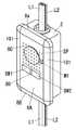
これらのスイッチボックス2は、例えばJISで規格化された大角形の1個モジュール寸法の埋め込み型の配線器具が3個取り付けることができる1連の取付枠4(図10参照)に対応して規格化されたスイッチボックスからなり、図2に示すように上部から配線盤1または他のスイッチボックス2から送り配線されてくる電力線L1及び情報線L2を導入するとともに、下部からは他のスイッチボックス2へ送り配線するための電力線L1及び情報線L2を導出している。そして各スイッチボックス2には基本機能モジュール8を接続するゲート装置3のボディを夫々取付枠4により取り付けてある。  Theseswitch boxes 2 are standardized corresponding to a series of mounting frames 4 (see FIG. 10) to which three large-sized square-type embedded wiring devices standardized by JIS can be mounted. As shown in FIG. 2, the power line L1 and the information line L2 sent from the wiring board 1 orother switch box 2 are introduced from the upper part as shown in FIG. 2, and theother switch box 2 is introduced from the lower part. A power line L1 and an information line L2 for leading and wiring are derived. The body of thegate device 3 to which thebasic function module 8 is connected is attached to eachswitch box 2 by theattachment frame 4.

この取付枠4は図10に示すように中央に器具取り付け用の窓孔4aを設けてあって、この窓孔4aに取り付け対象の器具本体の前部を背方から嵌め、左右両側の枠片に設けた係止手段に器具本体の両側に設けた被係止部を係止させて器具本体を固定するようになっている。そして上下枠片に設けた取付孔4bに挿通する取り付けねじ(図示せず)をスイッチボックス2のねじ孔(図示せず)に締結することで、器具本体ごとスイッチボックス2に取り付けられる。またスイッチボックス2を用いず、埋め込み孔を開口した壁パネルに取り付ける場合には所謂挟み金具で壁パネルを挟持させて取り付けたり、木ねじを用いて取り付けることもできるようになっている。  As shown in FIG. 10, themounting frame 4 is provided with awindow hole 4a for mounting the instrument in the center, and the front part of the instrument body to be mounted is fitted into thewindow hole 4a from the back, so that the left and right frame pieces The locked body provided on the both sides of the device main body is locked by the locking means provided on the device to fix the device main body. And the attachment screw | thread (not shown) penetrated to theattachment hole 4b provided in the up-and-down frame piece is fastened to the screw hole (not shown) of theswitch box 2, and it attaches to theswitch box 2 with the instrument main body. Further, when the mounting is performed on the wall panel with the embedded hole opened without using theswitch box 2, the wall panel can be clamped with a so-called clip fitting or can be mounted with a wood screw.

ゲート装置3は図11に示すようにボディ背面部に速結端子構造の接続端子部5a,5b及び送り配線用の接続端子部5a’、5b’を設け、夫々に対応する電力線L1、情報線L2を接続するようになっている。またボディ前面部には、送られてきた電力線L1と電気的に接続されている接触部を備えた電力路接続口6Aと、送られてきた情報線L2と電気的に接続されている情報路接続口6Bとを有しモジュール化した接続口6を図10に示すように備えている。  As shown in FIG. 11, thegate device 3 is provided with connectionterminal portions 5a and 5b having a quick connection terminal structure and connectionterminal portions 5a ′ and 5b ′ for feed wiring on the back surface of the body, and corresponding power lines L1 and information lines. L2 is connected. Further, on the front surface of the body, a powerpath connection port 6A having a contact portion electrically connected to the sent power line L1, and an information path electrically connected to the sent information line L2. Amodular connection port 6 having aconnection port 6B is provided as shown in FIG.

これら接続口6A,6Bは両者間の間隔及び内部の接触部の配列、開口部の形状等がシステムとして規格化されており、このゲート装置3のボディ前面部を覆うようにスイッチボックス2の前面開口側に取り付ける図12に示す基本機能モジュール8の背面部に設けたコネクタ7の被接続部7A、7Bが各接続口6A,6Bに着脱自在に結合されるようになっている。  Theseconnection ports 6A and 6B are standardized as a system in terms of the distance between them, the arrangement of internal contact portions, the shape of the opening, and the like. Connectedportions 7A and 7B of aconnector 7 provided on the back surface of thebasic function module 8 shown in FIG. 12 attached to the opening side are detachably coupled to theconnection ports 6A and 6B.

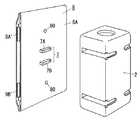
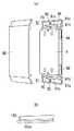
基本機能モジュール8は、後述する拡張機能モジュール10とで機能装置を構成するもので、図12,図13(a)に示す合成樹脂製(ABS等の非結晶性汎用プラスチック)で扁平なモジュール本体8A内に図15に示す回路を内蔵しているもので、背面部のコネクタ7の被接続部7A,7Bをゲート装置3の接続口6A,6Bに結合させることで、スイッチボックス2の前面開口を覆うとともに、周部のフランジをスイッチボックス2の前面開口周辺の壁面に重ねた状態となり、その状態で上、下部の中央に穿孔している取付孔80に取り付けねじ(図示せず)を前面部側から挿通させて取付枠4の上下枠に設けたねじ孔4cに螺入締結することでスイッチボックス2に取付枠4を介して取り付けられる。  Thebasic function module 8 constitutes a functional device with the extendedfunction module 10 described later, and is a flat module body made of synthetic resin (non-crystalline general-purpose plastic such as ABS) shown in FIGS. 12 and 13A. The circuit shown in FIG. 15 is built in 8A, and by connecting the connectedportions 7A and 7B of theconnector 7 on the back surface to theconnection ports 6A and 6B of thegate device 3, the front opening of theswitch box 2 is obtained. In addition, the mounting flange (not shown) is attached to the front surface of themounting hole 80 which is perforated in the center of the upper portion and the lower portion. It is attached to theswitch box 2 via theattachment frame 4 by being inserted from the part side and screwed into ascrew hole 4 c provided in the upper and lower frames of theattachment frame 4.

またモジュール本体8Aの前面部には、上、下の取付孔80の開口位置より上または下側位置において、図13(a)に示すようにモジュール本体8Aの幅方向に幅広溝81aと幅狭溝81bとからなる連結用溝部81を中央の仕切壁82で左右に二分されるように形成している。  Further, the front surface of the modulemain body 8A has awide groove 81a and a narrow width in the width direction of the modulemain body 8A as shown in FIG. 13A at a position above or below the opening position of the upper andlower mounting holes 80. A connectinggroove 81 comprising agroove 81b is formed to be divided into left and right by acentral partition wall 82.

この仕切壁82の左側または右側の連結用溝部81には図13(b)に示す合成樹脂製の連結体100の片側半分を仕切壁82に当たる位置まで嵌め込み、この連結体100の残り半分を図14に示すように拡張機能モジュール10側に同様に設けてある連結用溝部81に嵌め込むことで、基本機能モジュール8と拡張機能モジュール10とを機械的に結合できるようになっている。連結体100は背面に幅広溝81a,幅狭溝81bを仕切る仕切壁81cが嵌る溝100aを設け、両溝81a、81bに跨るように挿入される。そして基本機能モジュール8では前面部側から化粧カバー8Bを着脱自在に被着することで、また拡張機能モジュール10では蓋部83を閉じることで、両者の連結用溝部81に跨るように嵌め込んである連結体100が脱落しないように保持して連結状態を維持するようになっている。而して連結体100と連結用溝部81とが基本機能モジュール8と拡張機能モジュール10との連結手段を構成する。  A half of one side of the syntheticresin coupling body 100 shown in FIG. 13B is fitted into thecoupling groove 81 on the left or right side of thepartition wall 82 until it hits thepartition wall 82, and the other half of thecoupling body 100 is illustrated. As shown in FIG. 14, thebasic function module 8 and theextended function module 10 can be mechanically coupled by being fitted into a connectinggroove 81 that is similarly provided on the extendedfunction module 10 side. The connectingbody 100 is provided with agroove 100a in which apartition wall 81c for partitioning thewide groove 81a and thenarrow groove 81b is fitted on the back surface, and is inserted so as to straddle both thegrooves 81a and 81b. In thebasic function module 8, thedecorative cover 8 </ b> B is detachably attached from the front side, and in theextended function module 10, thelid 83 is closed so as to be fitted over the connectinggroove 81. A certainconnected body 100 is held so as not to fall off and is maintained in a connected state. Thus, the connectingbody 100 and the connectinggroove 81 constitute connecting means for thebasic function module 8 and theextended function module 10.

本実施形態の配線システムでは、機能によって複数の種類の基本機能モジュール8が準備されており、基本機能モジュール8は、図15に示すように、被接続部7Aを介して供給される商用電源ACを、安定した直流電圧からなる内部回路の動作電源+Vに変換するAC/DCコンバータ21と、被接続部7Bを介して接続される情報線L2を通じて双方向に伝送されるデジタル情報信号を送受信する通信伝送部22と、被接続部7Aを介して商用電源ACに接続される電源用コネクタ9A,9A’と、通信伝送部22、被接続部7Bを介して情報線L2に接続される情報用コネクタ9B,9B’と、通信伝送部22で受信されるデジタル情報信号からデータを取り込んで処理を行うとともに、当該基本機能モジュール8から他の基本機能モジュール8あるいは拡張機能モジュール10宛、あるいは情報線L2を介してデジタル情報信号を送る場合のデジタル情報生成処理を行う演算処理部23と、I/Oインターフェース24を介して演算処理部23との間でデータの授受を行って動作する機能部25とから構成され、これら各部は動作電源+Vを前記のAC/DCコンバータ21から供給されるのである。この機能部25の構成が基本機能モジュール8によって異なるのである。  In the wiring system of the present embodiment, a plurality of types ofbasic function modules 8 are prepared depending on functions, and thebasic function module 8 is a commercial power supply AC supplied via aconnected portion 7A as shown in FIG. Is transmitted / received to / from the AC /DC converter 21 that converts the power to the operating power source + V of the internal circuit composed of a stable DC voltage and the information line L2 connected via the connectedportion 7B. Information transmission connected to the information line L2 via thecommunication transmission unit 22, thepower connectors 9A and 9A 'connected to the commercial power supply AC via theconnected part 7A, and thecommunication transmission unit 22 and theconnected part 7B Data is acquired from the digital information signals received by theconnectors 9B and 9B 'and thecommunication transmission unit 22 and processed, and other basic function modules are processed from thebasic function module 8. Between thearithmetic processing unit 23 that performs digital information generation processing when the digital information signal is sent to themodule 8 or theextended function module 10 or via the information line L2, and thearithmetic processing unit 23 via the I /O interface 24. And afunctional unit 25 that operates by exchanging data, and these units are supplied with an operating power supply + V from the AC /DC converter 21. The configuration of thefunction unit 25 differs depending on thebasic function module 8.

基本機能モジュール8のモジュール本体8Aの両側側面の一方側は雄型の電源用コネクタ9A、情報用コネクタ9Bを、他方側には雌型の電源用コネクタ9A’、情報用コネクタ9B’を設けている。そして、これら電源用コネクタ9A,9A’の接触片に被接続部7Aの接触片を内部で接続することで、左右何れの方向に拡張機能モジュール10が連結されても商用電源ACを供給することができるようにしている。さらに、情報用コネクタ9B,9B’の接触片に通信伝送部22の入出力を接続することで、左右何れの方向に拡張機能モジュール10が連結されても情報信号の授受を行えるようにしている。なお、上記電源用コネクタ9A,9A’は、モジュール本体8Aの両側側面において一端側に偏倚して配置され、上記情報用コネクタ9B,9B’は、モジュール本体8Aの両側側面において他端側に偏倚して配置される。  Amale power connector 9A and aninformation connector 9B are provided on one side of both side surfaces of the modulemain body 8A of thebasic function module 8, and afemale power connector 9A 'and aninformation connector 9B' are provided on the other side. Yes. Then, by connecting the contact pieces of the connectedportion 7A to the contact pieces of thepower connectors 9A and 9A ′, the commercial power supply AC is supplied even if theextended function module 10 is connected in either direction. To be able to. Further, by connecting the input / output of thecommunication transmission unit 22 to the contact pieces of theinformation connectors 9B and 9B ′, the information signal can be exchanged even if theextended function module 10 is connected in either the left or right direction. . Thepower connectors 9A and 9A ′ are arranged to be biased to one end on both side surfaces of themodule body 8A, and theinformation connectors 9B and 9B ′ are biased to the other side on both side surfaces of themodule body 8A. Arranged.

これら電源用コネクタ9A,9A’、情報用コネクタ9B,9B’は、内部の接触部の配列、開口部の形状等がシステムとして規格化され、さらには同一面に配置された電源用コネクタと情報用コネクタとの間隔もシステムとして規格化されており、拡張機能モジュール10の後述する電源用コネクタ11A,11A’、情報用コネクタ11B,11B’が着脱自在に結合されるようになっている。  Thepower connectors 9A and 9A ′ and theinformation connectors 9B and 9B ′ are standardized as a system in the arrangement of the internal contact portions, the shape of the openings, and the power connector and information arranged on the same surface. The distance from the connector for the connector is also standardized as a system, andpower supply connectors 11A and 11A ′ andinformation connectors 11B and 11B ′, which will be described later, of theextended function module 10 are detachably coupled.

次に、本実施形態の配線システムでは、電力供給を受けて動作する機能によって複数の種類の拡張機能モジュール10が準備されており、拡張機能モジュール10は図16に示すように、電源用コネクタ11A,11A’と、情報用コネクタ11B,11B’と、電源用コネクタ11A,11A’いずれか一方を介して供給される商用電源ACを、安定した直流電圧からなる内部回路の動作電源+Vに変換するAC/DCコンバータ31と、情報用コネクタ11B,11B’を介して双方向に伝送されるデジタル情報信号を送受信する通信伝送部32と、通信伝送部32で受信されるデジタル情報信号からデータを取り込んで処理を行うとともに、当該拡張機能モジュール10から基本機能モジュール8あるいは他の拡張機能モジュール10宛、あるいは情報線L2を介してデジタル情報信号を送る場合のデジタル情報生成処理を行う演算処理部33と、I/Oインターフェース34を介して演算処理部33との間でデータの授受を行って動作する機能部35とから構成され、これら各部は動作電源+Vを前記のAC/DCコンバータ31から供給されるのである。この機能部35の構成が拡張機能モジュール10によって異なるのである。  Next, in the wiring system of the present embodiment, a plurality of types ofextended function modules 10 are prepared according to functions that operate by receiving power supply, and theextended function modules 10 include apower connector 11A as shown in FIG. , 11A ′, theinformation connectors 11B, 11B ′, and the commercial power supply AC supplied via any one of thepower connectors 11A, 11A ′ are converted into an operating power supply + V of an internal circuit composed of a stable DC voltage. The AC /DC converter 31, thecommunication transmission unit 32 that transmits and receives digital information signals transmitted bidirectionally via the information connectors 11 </ b> B and 11 </ b> B ′, and the digital information signal received by thecommunication transmission unit 32 captures data. And theextended function module 10 to thebasic function module 8 or anotherextended function module 10. Alternatively, data is exchanged between thearithmetic processing unit 33 that performs digital information generation processing when a digital information signal is transmitted via the information line L2 and thearithmetic processing unit 33 via the I /O interface 34. Each of these units is supplied with an operating power supply + V from the AC /DC converter 31. The configuration of thefunction unit 35 differs depending on theextended function module 10.

そして、拡張機能モジュール10は、基本的には図17(a)に示すようにモジュール本体10Aの高さ寸法を基本機能モジュール8と同じ高さ寸法に規格化され、また横幅寸法も規格化された単位モジュール寸法の整数倍に規格化されている。  In theextended function module 10, the height of themodule body 10A is basically standardized to the same height as that of thebasic function module 8 as shown in FIG. Standardized to an integral multiple of the unit module dimensions.

また、合成樹脂製(ABS等の非結晶性汎用プラスチック)で扁平なモジュール本体10Aの両側側面の一方側は雄型の電源用コネクタ11A、情報用コネクタ11Bを、他方側には雌型の電源用コネクタ11A’、情報用コネクタ11B’を設けている。上記電源用コネクタ11A,11A’は、モジュール本体10Aの両側側面において一端側に偏倚して配置され、上記情報用コネクタ11B,11B’は、モジュール本体10Aの両側側面において他端側に偏倚して配置される。これら電源用コネクタ11A,11A’、情報用コネクタ11B,11B’は、基本機能モジュール8の電源用コネクタ9A,9A’、情報用コネクタ9B,9B’と同様に、内部の接触部の配列、開口部の形状等がシステムとして規格化され、さらには同一面に配置された電源用コネクタと情報用コネクタとの間隔もシステムとして規格化されており、基本機能モジュール8の電源用コネクタ9A,9A’、情報用コネクタ9B,9B’、あるいは他の拡張機能モジュール10の電源用コネクタ11A,11A’、情報用コネクタ11B,11B’が着脱自在に結合されるようになっている。  Also, amale power connector 11A and aninformation connector 11B are provided on one side of both sides of theflat module body 10A made of synthetic resin (amorphous general-purpose plastic such as ABS), and a female power source is provided on the other side.Connector 11A 'andinformation connector 11B' are provided. Thepower connectors 11A and 11A ′ are biased to one end on both side surfaces of themodule body 10A, and theinformation connectors 11B and 11B ′ are biased to the other side on both side surfaces of themodule body 10A. Be placed. Thesepower connectors 11A and 11A ′ andinformation connectors 11B and 11B ′ are arranged in the same manner as thepower connectors 9A and 9A ′ andinformation connectors 9B and 9B ′ of thebasic function module 8, and the arrangement and opening of the internal contact portions. The shape of the unit is standardized as a system, and the interval between the power connector and the information connector arranged on the same plane is also standardized as a system. Thepower connectors 9A, 9A ′ of thebasic function module 8 are standardized. Theinformation connectors 9B and 9B ′ or thepower connectors 11A and 11A ′ and theinformation connectors 11B and 11B ′ of the otherextended function modules 10 are detachably coupled.

具体的には、雄型の電源用コネクタ11A、情報用コネクタ11Bは、基本機能モジュール8の雌型の電源用コネクタ9A’、情報用コネクタ9B’、あるいは他の拡張機能モジュール10の雌型の電源用コネクタ11A’、情報用コネクタ11B’に接続し、雌型の電源用コネクタ11A’、情報用コネクタ11B’は、基本機能モジュール8の雄型の電源用コネクタ9A、情報用コネクタ9B、あるいは他の拡張機能モジュール10の雄型の電源用コネクタ11A、情報用コネクタ11Bに接続する。  Specifically, themale power connector 11A and theinformation connector 11B are thefemale power connector 9A 'of thebasic function module 8, theinformation connector 9B', or the female connector of anotherextension function module 10. Connected to thepower connector 11A ′ and theinformation connector 11B ′, thefemale power connector 11A ′ and theinformation connector 11B ′ are themale power connector 9A, theinformation connector 9B of thebasic function module 8, or The otherextension function module 10 is connected to themale power connector 11A and theinformation connector 11B.

そして、モジュール本体10A内ではこれら電源用コネクタ11A,11A’の接触片を互いに接続しており、片側の電源用コネクタが隣接する基本機能モジュール8または拡張機能モジュール10の電源用コネクタに嵌合して電力を受け取る側(受電口)となると、他方の電源用コネクタが電力供給側(給電口)となる。  In themodule body 10A, the contact pieces of thesepower supply connectors 11A and 11A ′ are connected to each other, and the power supply connector on one side is fitted to the power supply connector of the adjacentbasic function module 8 or theextended function module 10. When the power is received (power reception port), the other power connector is the power supply side (power supply port).

さらに、情報用コネクタ(情報授受口)11B,11B’の接触片に通信伝送部32の入出力を接続することで、左右何れの方向に基本機能モジュール8や、他の拡張機能モジュール10が連結されても情報信号の授受を行えるようにしており、両側に隣接する基本機能モジュール8または拡張機能モジュール10との間で情報信号を授受できるようになっている。  Further, by connecting the input / output of thecommunication transmission unit 32 to the contact pieces of the information connectors (information transfer ports) 11B and 11B ′, thebasic function module 8 and otherextended function modules 10 are connected in either direction. However, the information signal can be exchanged, and the information signal can be exchanged with thebasic function module 8 or theextended function module 10 adjacent to both sides.

また、拡張機能モジュール10のモジュール本体10Aの形状は、背面を図17(b)、(c)に示すように平坦な面に形成して壁面に沿わせることができるようにしている。そして上下位置には上述の連結体100を基本機能モジュール8と同様に挿入するための幅広溝81a、幅狭溝81bからなる連結用溝部81を設けるとともに、この連結用溝部81を開閉する蓋部83を設け、連結体100を装着する際や外す場合にはこの蓋部83を開き、連結体100の装着状態を保持する際には上述したように閉じるようになっている(図17(c)参照)。  Further, the shape of the modulemain body 10A of theextended function module 10 is such that the back surface is formed as a flat surface as shown in FIGS. The upper and lower positions are provided with a connectinggroove portion 81 including awide groove 81a and anarrow groove 81b for inserting the connectingbody 100 in the same manner as thebasic function module 8, and a lid portion for opening and closing the connectinggroove portion 81. 83, thelid 83 is opened when the connectingbody 100 is attached or removed, and is closed as described above when the attached state of the connectingbody 100 is maintained (FIG. 17 (c). )reference).

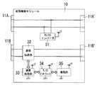
次に、拡張機能モジュール10の1つの形態である本実施形態の音響装置10aについて、以下説明する。図3,図4に示すように、音響装置10aは、拡張機能モジュール10と同様に、AC/DCコンバータ31、通信伝送部32、演算処理部33、I/Oインターフェース34、機能部35がモジュール本体10A内に収納され、モジュール本体10Aの両側側面の一方側は雄型の電源用コネクタ11A、情報用コネクタ11Bを、他方側には雌型の電源用コネクタ11A’、情報用コネクタ11B’を設けている。  Next, theacoustic device 10a of this embodiment which is one form of theextended function module 10 will be described below. As shown in FIGS. 3 and 4, theacoustic device 10 a includes an AC /DC converter 31, acommunication transmission unit 32, anarithmetic processing unit 33, an I /O interface 34, and afunctional unit 35, similar to theextended function module 10. The modulemain body 10A is housed in amain body 10A. One side of the both sides of the modulemain body 10A has amale power connector 11A and aninformation connector 11B, and the other side has afemale power connector 11A 'and aninformation connector 11B'. Provided.

モジュール本体10A内には図4に示すように、機能部35として、スピーカSP、マイクロホンM1、通話スイッチSW1、警報解除スイッチSW2、増幅部35a,35b、エコーキャンセル部35c,35dを備える。  As shown in FIG. 4, the modulemain body 10 </ b> A includes a speaker SP, a microphone M <b> 1, a call switch SW <b> 1, an alarm release switch SW <b> 2,amplification units 35 a and 35 b, and echocancellation units 35 c and 35 d asfunction units 35.

また、スピーカSP、マイクロホンM1に対向するモジュール本体10Aの前面には複数の音孔10Bや、通話スイッチSW1,警報解除スイッチSW2を前面に露出させる挿通孔10C,10Cが穿設されている(図3参照)。  In addition, a plurality ofsound holes 10B and insertion holes 10C and 10C for exposing the call switch SW1 and the alarm release switch SW2 to the front surface are formed in the front surface of the modulemain body 10A facing the speaker SP and the microphone M1 (see FIG. 3).

そして、他の部屋等から情報線L2を介して送信された音声信号は、エコーキャンセル部35dを介して増幅部35aで増幅された後、スピーカSPから出力される。また、通話スイッチSW1を操作することで通話可能状態となり、マイクロホンM1から出力された音声信号は増幅部35bで増幅された後、エコーキャンセル部35cを通過し、情報線L2を介して他の部屋等へ送信される。すなわち、部屋間で双方向の通話が可能なインターホンとしても機能するものである。  Then, an audio signal transmitted from another room or the like via the information line L2 is amplified by the amplifyingunit 35a via theecho canceling unit 35d and then output from the speaker SP. Further, by operating the call switch SW1, a call can be made, and the audio signal output from the microphone M1 is amplified by the amplifyingunit 35b, passes through theecho canceling unit 35c, and passes through the information line L2 to another room. Etc. That is, it also functions as an intercom that allows two-way calls between rooms.

また、本実施形態では、スピーカSPの近傍にマイクロホンM1が配置されており、スピーカSPの音声出力をマイクロホンM1が拾うことで発生するハウリングを防止するために、以下の処理を行う。まず、エコーキャンセル部35cは、エコーキャンセル部35dの出力を参照信号として取り込み、増幅部35bの出力に対して演算を施すことにより、スピーカSPからマイクロホンM1に回り込んだ音声情報信号をキャンセリングするものである。さらにエコーキャンセル部35dは、エコーキャンセル部35cの出力を参照信号として取り込み、I/Oインターフェース34の出力に対して演算を施すことにより、通話先の相手側でのスピーカからマイクロホンへの音声情報信号の回り込みをもキャンセリングするものである。  In the present embodiment, the microphone M1 is disposed in the vicinity of the speaker SP, and the following processing is performed to prevent howling that occurs when the microphone M1 picks up the sound output of the speaker SP. First, the echo cancelunit 35c cancels the audio information signal that has passed from the speaker SP to the microphone M1 by taking the output of the echo cancelunit 35d as a reference signal and performing an operation on the output of theamplification unit 35b. Is. Further, theecho canceling unit 35d takes the output of theecho canceling unit 35c as a reference signal, and performs an operation on the output of the I /O interface 34, so that an audio information signal from the speaker to the microphone on the other party side of the call destination It also cancels out wraparound.

なお、マイクロホンの数は1つに限定されるものではなく、状況に応じた複数のマイクロホンを配置して上記同様の処理を行えばよい。  Note that the number of microphones is not limited to one, and a plurality of microphones corresponding to the situation may be arranged to perform the same processing as described above.

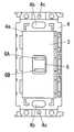
次に、図5は、基本機能モジュール8の1つの形態である本実施形態の音響装置8aを示しており、モジュール本体8A内には基本機能モジュール8と同様に、AC/DCコンバータ21、通信伝送部22、演算処理部23、I/Oインターフェース24、機能部25が収納されている。  Next, FIG. 5 shows anacoustic device 8a of the present embodiment, which is one form of thebasic function module 8, and the modulemain body 8A has an AC /DC converter 21, a communication, as in the case of thebasic function module 8. Atransmission unit 22, anarithmetic processing unit 23, an I /O interface 24, and afunction unit 25 are accommodated.

そして基本機能モジュール8の機能部25として、図6に示すように、スピーカSP、マイクロホンM1、通話スイッチSW1、警報解除スイッチSW2、増幅部35a,35b、エコーキャンセル部35c,35dを備え、音響装置10aと同様の機能を有する音響装置8aを構成する。なお、音響装置10aと同様の構成には同一の符号を付して説明は省略する。  As shown in FIG. 6, thefunction unit 25 of thebasic function module 8 includes a speaker SP, a microphone M1, a call switch SW1, an alarm release switch SW2,amplification units 35a and 35b, and echocancellation units 35c and 35d. Anacoustic device 8a having the same function as 10a is configured. In addition, the same code | symbol is attached | subjected to the structure similar to theaudio equipment 10a, and description is abbreviate | omitted.

また、スピーカSP、マイクロホンM1に対向するモジュール本体8Aの前面には複数の音孔8Cや、通話スイッチSW1,警報解除スイッチSW2を前面に露出させる挿通孔8Dが穿設され、化粧カバー8Bの前面に露出させている。  Also, a plurality of sound holes 8C andinsertion holes 8D for exposing the call switch SW1 and the alarm release switch SW2 to the front surface are formed in the front surface of themodule body 8A facing the speaker SP and the microphone M1, and the front surface of thedecorative cover 8B. It is exposed to.

次に、拡張機能モジュール10の1つの形態である本実施形態のタイマ装置10bについて、以下説明する。タイマ装置10bも、拡張機能モジュール10と同様に、AC/DCコンバータ31、通信伝送部32、演算処理部33、I/Oインターフェース34、機能部35がモジュール本体10A内に収納され、モジュール本体10Aの両側側面の一方側は雄型の電源用コネクタ11A、情報用コネクタ11Bを、他方側には雌型の電源用コネクタ11A’、情報用コネクタ11B’を設けている(図16,図17参照)。  Next, thetimer device 10b of this embodiment, which is one form of theextended function module 10, will be described below. Similarly to theextended function module 10, thetimer device 10b includes an AC /DC converter 31, acommunication transmission unit 32, anarithmetic processing unit 33, an I /O interface 34, and afunction unit 35 housed in the modulemain body 10A. On one side of each side, amale power connector 11A and aninformation connector 11B are provided, and on the other side, afemale power connector 11A 'and aninformation connector 11B' are provided (see FIGS. 16 and 17). ).

タイマ装置10bのモジュール本体10A内には図7に示すように、機能部35として、CPU部35m、タイマ部35n、表示部35p、時刻設定スイッチSW4、タイマ時間設定スイッチSW5、UPボタンSW6、DOWNボタンSW7を備える。  In the modulemain body 10A of thetimer device 10b, as shown in FIG. 7, as afunction unit 35, aCPU unit 35m, atimer unit 35n, adisplay unit 35p, a time setting switch SW4, a timer time setting switch SW5, an UP button SW6, DOWN A button SW7 is provided.

また、タイマ装置10bのモジュール本体10Aの前面には、表示部35p、時刻設定スイッチSW4、タイマ時間設定スイッチSW5、UPボタンSW6、DOWNボタンSW7が露出している(図2参照)。  Further, thedisplay unit 35p, the time setting switch SW4, the timer time setting switch SW5, the UP button SW6, and the DOWN button SW7 are exposed on the front surface of the modulemain body 10A of thetimer device 10b (see FIG. 2).

そして、CPU部35mは、タイマ部35n、表示部35p、時刻設定スイッチSW4、タイマ時間設定スイッチSW5、UPボタンSW6、DOWNボタンSW7が接続されており、表示部35pには図8(a)(b)に示すように各種表示がなされる。通常は、タイマ部35nで生成された時刻データに基づいて、年、月、日、時刻を現在時刻351として表示部35pに表示させる。  TheCPU unit 35m is connected to atimer unit 35n, adisplay unit 35p, a time setting switch SW4, a timer time setting switch SW5, an UP button SW6, and a DOWN button SW7. Various displays are made as shown in b). Usually, based on the time data generated by thetimer unit 35n, the year, month, day, and time are displayed on thedisplay unit 35p as thecurrent time 351.

ここで、電力線L1,情報線L2には、上記基本機能モジュール8、拡張機能モジュール10以外に、主装置110が接続されており(図9参照)、主装置110は各機能装置からの情報信号を中継し、該情報信号に含まれるID等を参照して対応する機能装置へ情報信号を送信する動作を行う。具体的には、主装置110において、複数の機能装置からの情報信号を複数チャネル制御(時分割多重制御等)することで、通信効率の向上を図っている。また主装置110は、複数の音声情報(音声メッセージ、報知音、音楽等)を格納した音声格納手段を構成する音声IC111を内蔵している。  Here, themain device 110 is connected to the power line L1 and the information line L2 in addition to thebasic function module 8 and the extended function module 10 (see FIG. 9), and themain device 110 receives information signals from the respective function devices. And the information signal is transmitted to the corresponding functional device with reference to the ID or the like included in the information signal. Specifically, themain device 110 attempts to improve communication efficiency by performing multiple channel control (such as time division multiplexing control) on information signals from a plurality of functional devices. Themain apparatus 110 includes avoice IC 111 that constitutes a voice storage unit that stores a plurality of voice information (voice message, notification sound, music, etc.).

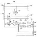
以下、一例として図1に概略を示す配線システムの動作について説明する。まず、電力線L1,情報線L2は建物200内の壁面内に先行配線されており、各部屋R1,R2において上記音響装置8a,10a、タイマ装置10bを含む機能装置が設置されている。  Hereinafter, the operation of the wiring system schematically shown in FIG. 1 will be described as an example. First, the power line L1 and the information line L2 are preliminarily wired in the wall surface in thebuilding 200, and functional devices including theacoustic devices 8a and 10a and thetimer device 10b are installed in the rooms R1 and R2.

まず、部屋R1においては、天井面のようなハイポジションHPに設けられたスイッチボックス2のゲート装置3に(図9参照)、引掛栓刃接続部60を備えた基本機能モジュール8dに人感センサ機能を有する拡張機能モジュール10c(以後、人感センサ装置10cと称す)が連結され、基本機能モジュール8dには照明器具120を接続する。  First, in the room R1, the human sensor is added to thebasic function module 8d including the hookingblade connecting portion 60 in thegate device 3 of theswitch box 2 provided in the high position HP such as the ceiling surface (see FIG. 9). Anextended function module 10c having a function (hereinafter referred to as ahuman sensor device 10c) is connected, and alighting fixture 120 is connected to thebasic function module 8d.

さらに、壁スイッチ等で推奨される室内の壁面のような高さ位置(ミドルポジションMP)に設けられたスイッチボックス2のゲート装置3には(図9参照)、照明器具120をオン/オフする壁スイッチを構成する基本機能モジュール8bに、タイマ装置10bや、音響装置10aが連結される。  Further, thelighting apparatus 120 is turned on / off in thegate device 3 of theswitch box 2 provided at a height position (middle position MP) such as a wall surface recommended by a wall switch or the like (see FIG. 9). Thetimer device 10b and theacoustic device 10a are connected to thebasic function module 8b constituting the wall switch.

ここで、照明器具をオン/オフする壁スイッチを構成する基本機能モジュール8bの機能部25は、図18に示すように操作スイッチSW3と、操作スイッチSW3の操作データを生成して送るデータ生成機能を有するCPU部25aとで構成され、化粧カバー8Bの前面には図2に示すように操作スイッチSW3の操作部を露出させている。  Here, thefunction unit 25 of thebasic function module 8b that constitutes the wall switch for turning on / off the luminaire, as shown in FIG. 18, generates and sends operation data of the operation switch SW3 and operation switch SW3. The operation unit of the operation switch SW3 is exposed on the front surface of thedecorative cover 8B as shown in FIG.

また、部屋R2においては、ハイポジションHPに設けられたスイッチボックス2のゲート装置3に(図9参照)、引掛栓刃接続部60を備えた基本機能モジュール8dに人感センサ装置10cが連結され、基本機能モジュール8dには照明器具120を接続する。  In the room R2, thehuman sensor device 10c is connected to thegate device 3 of theswitch box 2 provided in the high position HP (see FIG. 9) and thebasic function module 8d having the hookingblade connecting portion 60. Theluminaire 120 is connected to thebasic function module 8d.

さらに、ミドルポジションMPに設けられたスイッチボックス2のゲート装置3には(図9参照)、音響装置8aが接続される。  Furthermore, anacoustic device 8a is connected to thegate device 3 of theswitch box 2 provided at the middle position MP (see FIG. 9).

そして、タイマ装置10bの時刻設定スイッチSW4を操作した後、UPボタンSW6、DOWNボタンSW7を操作して任意の設定時刻352をセットした場合(図8(a)参照、ここでは7:00にセット)、CPU部35mは、タイマ部35nで生成される時刻データが設定時刻352に一致すると、所定の報知制御を行う情報信号を出力し、情報線L2に伝送する。  Then, after the time setting switch SW4 of thetimer device 10b is operated, the UP button SW6 and the DOWN button SW7 are operated to set an arbitrary setting time 352 (see FIG. 8A, here set to 7:00) When the time data generated by thetimer unit 35n matches theset time 352, theCPU unit 35m outputs an information signal for performing predetermined notification control and transmits the information signal to the information line L2.

上記報知制御を行う情報信号をタイマ装置10bから情報線L2を介して受けた主装置110は、例えば設定時刻352が朝の時間帯であれば、音声IC111に格納している複数の音声情報から「ピーピーピー、朝です」という音声情報を選択し、該音声情報を情報線L2を介して音響装置10aへ伝送し、音響装置10aは、スピーカSPから「ピーピーピー、朝です」という音声を出力する。すなわち、目覚ましアラームとして機能する。なお、設定時刻352の時間帯、ユーザの生活パターン等に応じて、選択する音声情報は変えればよい。  Themain device 110 that has received the information signal for performing the notification control from thetimer device 10b via the information line L2, for example, from the plurality of audio information stored in theaudio IC 111 if theset time 352 is a morning time zone. The voice information “Peep, morning” is selected, and the voice information is transmitted to theaudio device 10a via the information line L2. Theaudio device 10a outputs the voice “Peep, morning” from the speaker SP. That is, it functions as an alarm alarm. Note that the audio information to be selected may be changed according to the time zone of theset time 352, the user's life pattern, and the like.

あるいは、タイマ装置10bのタイマ時間設定スイッチSW5を操作した後、UPボタンSW6、DOWNボタンSW7を操作して所望のタイマ時間353をセットした場合(図8(b)参照、ここでは300秒にセット)、CPU部35mは、タイマ部35nで生成される時刻データに基づいて計時動作を開始し、計時時間がタイマ時間353に一致すると、所定の報知制御を行う情報信号を出力し、情報線L2に伝送する。  Alternatively, when the timer time setting switch SW5 of thetimer device 10b is operated and then the UP button SW6 and the DOWN button SW7 are operated to set a desired timer time 353 (see FIG. 8B, here set to 300 seconds) ), TheCPU unit 35m starts a time counting operation based on the time data generated by thetimer unit 35n, and outputs an information signal for performing predetermined notification control when the time counting time coincides with thetimer time 353, and the information line L2 Transmit to.

上記報知制御を行う情報信号をタイマ装置10bから情報線L2を介して受けた主装置110は、音声IC111に格納している複数の音声情報から「時間です」という音声情報を選択し、該音声情報を情報線L2を介して音響装置10aへ伝送し、音響装置10aは、スピーカSPから「時間です」という音声を出力する。すなわち、キッチンタイマ機能等として用いることができる。なお、ユーザの生活パターン等に応じて、選択する音声情報は変えればよい。  Themain device 110 that has received the information signal for performing the notification control from thetimer device 10b via the information line L2 selects the audio information “It is time” from the plurality of audio information stored in theaudio IC 111, and the audio The information is transmitted to theacoustic device 10a via the information line L2, and theacoustic device 10a outputs a voice “It is time” from the speaker SP. That is, it can be used as a kitchen timer function or the like. In addition, what is necessary is just to change the audio | voice information to select according to a user's life pattern.

そして、上記タイマ時間353をセットしたユーザが部屋R1から部屋R2へ移動した場合、主装置110は、各部屋R1,R2に設置した人感センサ装置10cによってユーザの移動を検知し、上記音声情報を部屋R2の音響装置8aへ伝送し、音響装置8aのスピーカSPから「時間です」という音声を出力させる。  When the user who sets thetimer time 353 moves from the room R1 to the room R2, themain device 110 detects the movement of the user by thehuman sensor device 10c installed in each of the rooms R1 and R2, and the audio information Is transmitted to thesound device 8a in the room R2, and the sound "It is time" is output from the speaker SP of thesound device 8a.

また、主装置110は、音響装置8aまたは10aへ上記音声情報を伝送するとともに、部屋R1,R2のうちユーザが在室している部屋に設置した照明器具120を例えば点滅制御する情報信号を情報線L2を介して伝送しており、聴覚だけでなく、光を用いた視覚によっても設定時間に達したことを報知できる。  Themain device 110 transmits the audio information to theacoustic device 8a or 10a, and information signal for controlling thelighting fixture 120 installed in the room where the user is present among the rooms R1 and R2, for example. It is transmitted via the line L2, and it can be notified that the set time has been reached not only by hearing but also by vision using light.

さらに、図1に示すように、ミドルポジションMPに設けられたスイッチボックス2のゲート装置3に(図9参照)、文字をテキスト表示する表示手段を備えた基本機能モジュール8eを接続し、主装置110は上記音声情報を伝送するとともに、基本機能モジュール8eへメッセージ情報を含む情報信号を情報線L2を介して伝送しており、基本機能モジュール8eは伝送されたメッセージ情報をテキスト表示して、聴覚だけでなく、テキストを用いた視覚でも設定時間に達したことを報知している。  Further, as shown in FIG. 1, abasic function module 8e having a display means for displaying characters is connected to thegate device 3 of theswitch box 2 provided at the middle position MP (see FIG. 9). 110 transmits the audio information and transmits an information signal including message information to thebasic function module 8e via the information line L2. Thebasic function module 8e displays the transmitted message information in text, Not only that, it is informed that the set time has been reached by visual observation using text.

また、上記主装置110は、情報線L2、ゲートウェイGW、インターネット網NTを介して外部のホストコンピュータHCに接続されており、ホストコンピュータHCにアクセスして、データをダウンロードすることで、主装置110の音声IC111内に格納する音声情報を変更する。すなわち、音声ICを取り出すことなく、音声情報の追加、変更、更新、削除を容易に行うことができる。  Themain device 110 is connected to an external host computer HC via the information line L2, the gateway GW, and the Internet network NT, and accesses the host computer HC to download data. The audio information stored in theaudio IC 111 is changed. That is, it is possible to easily add, change, update, and delete audio information without taking out the audio IC.

このように本配線システムでは、音響装置10a,8a、タイマ装置10bを配線システムに接続するだけで、屋内のどこであってもタイマ機能と連動した最適な音声情報を出力することができる。  As described above, in this wiring system, it is possible to output optimum audio information linked with the timer function anywhere in the room simply by connecting theacoustic devices 10a and 8a and thetimer device 10b to the wiring system.

なお、タイマ装置10bと同様の機能を有する基本機能モジュール8に音響装置10aを連結しても、上記同様の配線システムを構成できる。  Even if theacoustic device 10a is connected to thebasic function module 8 having the same function as thetimer device 10b, the same wiring system as described above can be configured.

また、本配線システムにおいては、例えば図2に示すように、照明器具のオン/オフする壁スイッチを構成する基本機能モジュール8bをゲート装置3に接続し、基本機能モジュール8bの右側部には上記タイマ装置10bを接続し、拡張機能モジュール10bの右側部には上記音響装置10aを接続することで、壁スイッチ機能、タイマ機能等の様々な機能装置に音声情報出力機能を追加することができる。あるいは、予め設置している音響装置10aに新たなタイマ装置10bを接続することができる。  Further, in this wiring system, for example, as shown in FIG. 2, thebasic function module 8b constituting the wall switch for turning on / off the lighting fixture is connected to thegate device 3, and the right side of thebasic function module 8b An audio information output function can be added to various functional devices such as a wall switch function and a timer function by connecting thetimer device 10b and connecting theacoustic device 10a to the right side of theextended function module 10b. Alternatively, anew timer device 10b can be connected to theacoustic device 10a installed in advance.

この場合、タイマ装置10bの電源用コネクタ11A’、情報用コネクタ11B’が、屋内の天井面、壁面、床面に設置されて電力及び情報信号を伝送する少なくとも1系統の配線に電気的に接続された第1の接続部に相当し、音響装置10aの電源用コネクタ11A、情報用コネクタ11Bが、第1の接続部から電力供給を受け、第1の接続部との間で情報信号を授受するための第2の接続部に相当する。さらに音響装置10aの右側部に所定機能を有する拡張機能モジュール(図示無し)を接続すれば、音響装置10aの電源用コネクタ11A’、情報用コネクタ11B’が、拡張機能モジュールに電力を供給し、拡張機能モジュールとの間で情報信号を授受するための第3の接続部に相当する。  In this case, thepower connector 11A ′ and theinformation connector 11B ′ of thetimer device 10b are electrically connected to at least one line of wiring that is installed on the indoor ceiling surface, wall surface, and floor surface and transmits power and information signals. Thepower connector 11A and theinformation connector 11B of theaudio device 10a are supplied with power from the first connection unit and exchange information signals with the first connection unit. This corresponds to the second connection part for Furthermore, if an extended function module (not shown) having a predetermined function is connected to the right side of theacoustic device 10a, thepower connector 11A ′ and theinformation connector 11B ′ of theacoustic device 10a supply power to the expanded function module. This corresponds to a third connection unit for exchanging information signals with the extended function module.

したがって、音響装置10aは、予め同一に配線されている電力線L1、情報線L2にゲート装置3、基本機能モジュール8、他の拡張機能モジュール10を介して接続することで、電力路と情報路とを同時に確保でき、新たに配線工事を行う必要がなく、施工性に優れている。また、基本機能モジュール8、他の拡張機能モジュール10と同一の情報線L2を用いることで、音響装置10aと基本機能モジュール8、他の拡張機能モジュール10との間の連動制御を容易に行なうことができ、拡張性に優れたものとなる。  Therefore, theacoustic device 10a is connected to the power line L1 and the information line L2 that are previously wired in the same way through thegate device 3, thebasic function module 8, and the otherextended function module 10, thereby allowing the power path and the information path to be connected. Can be secured at the same time, and there is no need to perform new wiring work, and the construction is excellent. In addition, by using the same information line L2 as thebasic function module 8 and the otherextended function module 10, it is possible to easily perform the interlock control between theacoustic device 10a and thebasic function module 8 and the otherextended function module 10. Can be expanded and has excellent extensibility.

また、音響装置8aを用いる場合には、基本機能モジュールとして音響装置8a単体で用いることができ、さらには必要に応じて、電源用コネクタ9A,9A’、情報用コネクタ9B,9B’を介して側部に拡張機能モジュール10を連結すればよい。この場合、ゲート装置3の電力路接続口6A、情報路接続口6Bからなる接続口6が、屋内の天井面、壁面、床面に設置されて電力及び情報信号を伝送する少なくとも1系統の配線に電気的に接続された第1の接続部に相当し、音響装置8aの被接続部7A、被接続部7Bからなるコネクタ7が、第1の接続部から電力供給を受け、第1の接続部との間で情報信号を授受するための第2の接続部に相当する。  When theacoustic device 8a is used, theacoustic device 8a can be used alone as a basic function module, and further, via thepower connectors 9A and 9A ′ and theinformation connectors 9B and 9B ′ as necessary. What is necessary is just to connect theextended function module 10 to a side part. In this case, theconnection port 6 including the powerpath connection port 6 </ b> A and the informationpath connection port 6 </ b> B of thegate device 3 is installed on the indoor ceiling surface, wall surface, and floor surface, and transmits at least one system wiring. Theconnector 7 including the connectedportion 7A and theconnected portion 7B of theaudio device 8a is supplied with electric power from the first connecting portion, and is connected to the first connection portion. This corresponds to a second connection unit for exchanging information signals with the unit.

さらに音響装置8aの右側部あるいは左側部に所定機能を有する拡張機能モジュール(図示無し)を接続すれば、音響装置8aの電源用コネクタ9A,9A’、情報用コネクタ9B,9B’が、拡張機能モジュールに電力を供給し、拡張機能モジュールとの間で情報信号を授受する。  Further, if an extended function module (not shown) having a predetermined function is connected to the right side or the left side of theaudio device 8a, thepower connectors 9A and 9A 'and theinformation connectors 9B and 9B' of theaudio device 8a are expanded functions. Power is supplied to the module, and information signals are exchanged with the extended function module.

したがって、音響装置8aは、予め同一に配線されている電力線L1、情報線L2にゲート装置3を介して接続することで、電力路と情報路とを同時に確保でき、新たに配線工事を行う必要がなく、施工性に優れている。また、他の基本機能モジュール8、拡張機能モジュール10と同一の情報線L2を用いることで、音響装置8aと他の基本機能モジュール8、拡張機能モジュール10との間の連動制御を容易に行なうことができ、拡張性に優れたものとなる。  Therefore, theacoustic device 8a can secure the power path and the information path at the same time by connecting to the power line L1 and the information line L2 wired in advance in advance through thegate device 3, and it is necessary to newly perform wiring work. No workability and excellent workability. Further, by using the same information line L2 as the otherbasic function module 8 and theextended function module 10, it is possible to easily perform the interlock control between theacoustic device 8a and the otherbasic function module 8 and theextended function module 10. Can be expanded and has excellent extensibility.

基本機能モジュール8としては上記以外に、コンセント機能を有するものや、モニタ機能を有するもの等がある。  Other than the above, thebasic function module 8 includes those having an outlet function and those having a monitor function.

拡張機能モジュール10としては上記以外に、空調機器の運転操作器や、空調機器の温度設定器や、電力供給を利用した電気カミソリ、電動歯ブラシ、携帯オーディオプレーヤ等の充電器、照明器具や空調機器等のリモコン赤外線を有するもの等がある。また音声情報だけでなく、監視カメラ等で撮像した映像の伝送機能や、映像のモニタ機能を有するインターホンの親機,子機もある。  In addition to the above, theextended function module 10 includes an air conditioner operation controller, an air conditioner temperature setting device, an electric razor using electric power supply, an electric toothbrush, a charger such as a portable audio player, a lighting device, and an air conditioner. And the like having remote control infrared rays. In addition to audio information, there are interphone master and slave units that have a transmission function for video captured by a surveillance camera or the like, and a video monitoring function.

なお、本発明の機能装置を用いる配線システムの情報信号の伝送方式としては、ベースバンド伝送またはブロードバンド伝送の何れを採用しても良く、またプロトコルも何れでも良いが、音声、映像などを用いるインターホンの親機、子機との間にはJT−H232パケットを基づいて音声・映像を相互に送るようし、また制御系においては操作側からの操作データにより1乃至複数を操作できるような1対1または1対Nの対応が可能なユニキャスト、ブロードキャストに対応する経路制御プロトコルを採用すれば良く、特に限定されるものではないので、説明は省略する。またゲート装置3間の使用プロトコルと、ゲート装置3に連なる機能モジュール8,10での使用プロトコルを異ならせ、例えばゲート装置3でプロトコル変換を行うようにしても良い。  In addition, as a transmission system of the information signal of the wiring system using the functional device of the present invention, either baseband transmission or broadband transmission may be adopted and any protocol may be used. A pair of audio and video is sent to and from the master unit and slave unit based on JT-H232 packets, and one or more can be operated by operation data from the operation side in the control system. A route control protocol corresponding to unicast and broadcast capable of one-to-one or one-to-N correspondence may be employed, and is not particularly limited, and thus description thereof is omitted. Further, the protocol used between thegate devices 3 and the protocol used in thefunctional modules 8 and 10 connected to thegate device 3 may be made different, for example, the protocol conversion may be performed by thegate device 3.

而して機能装置を構成する基本機能モジュール8を使用するに当たっては、まず、ゲート装置3を予め建物の適所の壁面に埋設してあるスイッチボックス2に取付枠4を介して取り付け、先行配線されている電力線L1,情報線L2の接続を行う。その後、ゲート装置3の前面部に設けられた電線路接続口6A,6Bに対して基本機能モジュール8のコネクタ7の対応する被接続部7A,7Bを接続するとともに、基本機能モジュール8をゲート装置3の前面部を覆うように取付枠4に取り付ける。この基本機能モジュール8はこの取り付けた状態において壁面よりも前面部が突出し、両側面が室内側に露出することになる。  Thus, in using thebasic function module 8 constituting the functional device, first, thegate device 3 is first attached to theswitch box 2 embedded in the appropriate wall surface of the building via the mountingframe 4 and wired in advance. The power line L1 and the information line L2 are connected. Thereafter, the correspondingconnected portions 7A and 7B of theconnector 7 of thebasic function module 8 are connected to the electricwire connection ports 6A and 6B provided on the front surface portion of thegate device 3, and thebasic function module 8 is connected to the gate device. 3 is attached to theattachment frame 4 so as to cover the front surface portion of theframe 3. When thebasic function module 8 is attached, the front surface portion protrudes from the wall surface, and both side surfaces are exposed to the indoor side.

そして、拡張機能モジュール10は基本機能モジュール8の露出した両側側面の一方に片側の側面を面接させてコネクタ接続し、この状態で連結体100を用いて拡張機能モジュール10と基本機能モジュール8とを機械的に連結する。これによって基本機能モジュール8と拡張機能モジュール10とで機能装置が構成されることになる。このとき拡張機能モジュール10の背面はスイッチボックス2の側方の壁面に沿うことになり、例えば壁面にクロス貼り等が施されている場合、拡張機能モジュール10の背面の位置が多少のずれていてもそれを吸収して背面を壁部に密接させた状態に配設することができ、拡張機能モジュール10の前面部から操作力等が加わっても連結部位に加わる荷重を軽減することができる。  Then, theextended function module 10 is connected to one of the exposed side surfaces of thebasic function module 8 by connecting the side surface of one side to the connector, and in this state, theextended function module 10 and thebasic function module 8 are connected using thecoupling body 100. Connect mechanically. Thereby, thebasic function module 8 and theextended function module 10 constitute a functional device. At this time, the back surface of theextended function module 10 is along the side wall surface of theswitch box 2. For example, when the wall surface is cross-bonded or the like, the position of the back surface of theextended function module 10 is slightly shifted. In addition, it can be disposed in a state in which the back surface is in close contact with the wall portion, and even if an operation force or the like is applied from the front surface portion of theextended function module 10, the load applied to the connection portion can be reduced.

さらに先に連結した拡張機能モジュール10に別の拡張機能モジュール10を連結する場合には、対向側面を面接させてコネクタ接続した状態で連結体100により互いに機械的に連結する。このようにして図2に示すように順次拡張機能モジュール10(10a,10b...)を側方に連結することができる。  Further, when anotherextended function module 10 is connected to the previously connectedextended function module 10, theextended function modules 10 are mechanically connected to each other by the connectingbody 100 in a state where the opposing side surfaces are in contact with each other and are connected by connectors. In this way, as shown in FIG. 2, the extended function modules 10 (10a, 10b...) Can be sequentially connected to the sides.

なお、基本機能モジュール8は両側に拡張機能モジュール10を連結することができるため、基本機能モジュール8の両側方向に拡張機能モジュール10を連結しても良い。このようにして拡張機能モジュール10を連結した後、両端に位置する拡張機能モジュール10または基本機能モジュール8の連結部位の側部に着脱自在にエンドカバー101を被着することで、拡張機能モジュール10の連結施工が完了することになる。なお、基本機能モジュール8に拡張機能モジュール9を連結しない状態、つまり未使用のまま置いておく場合にはエンドカバー101を基本機能モジュール8の両側部に被着する。  Since thebasic function module 8 can connect theextended function module 10 to both sides, theextended function module 10 may be connected to both sides of thebasic function module 8. After theextended function module 10 is connected in this way, theend cover 101 is detachably attached to the side of the connection portion of theextended function module 10 or thebasic function module 8 located at both ends, so that theextended function module 10 is attached. Will be completed. When theextended function module 9 is not connected to thebasic function module 8, that is, when it is left unused, theend cover 101 is attached to both sides of thebasic function module 8.

そして、基本機能モジュール8の化粧カバー8Bの上辺,下辺、拡張機能モジュール10の上辺,下辺に設けた蓋部83、エンドカバー101で構成される枠体は、JISで規格化されたワイドハンドル形スイッチプレート(JIS8316)と略同様の形状を有するもので、既に設置されているワイドハンドル形スイッチ等との見た目の統一感が得られる。なお、この枠体の形状は上記ワイドハンドル形スイッチプレートの形状に限定されるものではなく、JISで規格化された大角形連用配線器具に用いるプレートと略同様の形状であれば、既設のコンセント等の埋込形配線器具との見た目の統一感を得ることができる。  The frame composed of the upper and lower sides of thedecorative cover 8B of thebasic function module 8, thelid 83 provided on the upper and lower sides of theextended function module 10, and theend cover 101 is a wide handle type standardized by JIS. It has substantially the same shape as the switch plate (JIS8316), and it provides a uniform appearance with the wide handle type switch that has already been installed. Note that the shape of the frame is not limited to the shape of the wide handle type switch plate, but if the shape is substantially the same as the plate used for the large-angle continuous wiring apparatus standardized by JIS, It is possible to obtain a uniform appearance with an embedded wiring device such as the above.

また、基本機能モジュール8,拡張機能モジュール10の横幅方向、高さ方向の寸法は、両側部にエンドカバー101を被着した状態で、JISで規格化された大角形連用配線器具に用いるプレートと同一寸法となるように形成されており、さらに基本機能モジュール8,拡張機能モジュール10の厚さ寸法は同一寸法で各々形成されているので、施工後に別の基本機能モジュール8、拡張機能モジュール10に容易に交換できる。  Further, the dimensions of thebasic function module 8 and theextended function module 10 in the width direction and the height direction are the plate used for the large-angle continuous wiring apparatus standardized by JIS with the end covers 101 attached to both sides. Thebasic function module 8 and theextended function module 10 are formed to have the same dimensions, and the thickness dimensions of thebasic function module 8 and theextended function module 10 are the same. Can be easily replaced.

また、基本機能モジュール8に連結できる拡張機能モジュール10の数は連結部位に加わる荷重の大きさにより制限があり、また基本機能モジュール8の電力供給能力によっても制限される。  In addition, the number ofextended function modules 10 that can be connected to thebasic function module 8 is limited by the magnitude of the load applied to the connection site, and is also limited by the power supply capability of thebasic function module 8.

ここで例えば図9に示すように建物内の適所において埋め込み配設している1乃至複数のスイッチボックス2の内、室内の天井面のようなハイポジションHPに設けられたスイッチボックス2のゲート装置3には引掛栓刃接続部60を備えた基本機能モジュール8dが接続され、基本機能モジュール8dには例えば人感センサ61が設けられた拡張機能モジュール10cなどが連結される。あるいは、ゲート装置3にスピーカSPのみを備えた基本機能モジュール8cが接続される。  Here, for example, as shown in FIG. 9, the gate device of theswitch box 2 provided in a high position HP such as an indoor ceiling surface among the one or a plurality ofswitch boxes 2 which are embedded and disposed at appropriate positions in the building. 3 is connected to abasic function module 8d having a hookingblade connecting portion 60, and thebasic function module 8d is connected to, for example, anextended function module 10c provided with ahuman sensor 61. Alternatively, thebasic function module 8c having only the speaker SP is connected to thegate device 3.

壁スイッチ等で推奨される室内の壁面のような高さ位置(ミドルポジションMP)に設けられたスイッチボックス2のゲート装置3には照明器具をオン/オフする壁スイッチを構成する基本機能モジュール8bに、タイマ装置10bや、音響装置10aが連結される。あるいはミドルポジションMPのスイッチボックス2のゲート装置3にはモニタ装置64を備えた基本機能モジュール8を接続している。  Abasic function module 8b constituting a wall switch for turning on / off a lighting fixture is provided in thegate device 3 of theswitch box 2 provided at a height position (middle position MP) such as a wall surface recommended by a wall switch or the like. In addition, thetimer device 10b and theacoustic device 10a are connected. Alternatively, thebasic function module 8 including themonitor device 64 is connected to thegate device 3 of theswitch box 2 in the middle position MP.

さらに床面を含む足元付近(ローポジションLP)に設けられたスイッチボックス2のゲート装置3には電源コンセント部62を備えた基本機能モジュール8が接続され、更に足元灯63を構成する拡張機能モジュール10が連結され、あるいは、ゲート装置3にスピーカSPのみを備えた基本機能モジュール8cが接続されている。  Furthermore, abasic function module 8 having apower outlet 62 is connected to thegate device 3 of theswitch box 2 provided in the vicinity of the foot including the floor (low position LP), and an extended function module constituting thefoot lamp 63. Or abasic function module 8c having only a speaker SP is connected to thegate device 3.

以上のようにして配設施工が終了し、システムが完成した後は、対応する基本機能モジュール8、拡張機能モジュール10間で情報信号の授受を行う。  After the installation work is completed as described above and the system is completed, information signals are exchanged between the correspondingbasic function module 8 and theextended function module 10.

また、本実施形態では拡張機能モジュール10や基本機能モジュール8の追加や削除に特別な施工が不要となり、そのため一般ユーザーの好みに合わせて拡張機能モジュール10を基本機能モジュール8に連結するだけで、拡張性が確保される。  Further, in this embodiment, no special construction is required for the addition or deletion of theextended function module 10 or thebasic function module 8, and therefore, only by connecting theextended function module 10 to thebasic function module 8 according to general user preference, Extensibility is ensured.

なお、本実施形態に用いるゲート装置3は取付枠4でスイッチボックス2に取り付けているが、スイッチボックス2の奥壁に直接取り付け、基本機能モジュール8をスイッチボックス2に取り付ける構成としても勿論良い。  Although thegate device 3 used in the present embodiment is attached to theswitch box 2 with theattachment frame 4, it is of course possible to attach it directly to the back wall of theswitch box 2 and attach thebasic function module 8 to theswitch box 2.

また、本実施形態の音響装置8a,10aはスピーカSPとマイクロホンM1との両方を具備してインターホン装置としても機能するものであるが、マイクロホンM1を省略してスピーカSPのみを具備した音声情報出力機能のみを備える構成としてもよい。  Theacoustic devices 8a and 10a according to the present embodiment include both the speaker SP and the microphone M1 and function as an interphone device. However, the audio information output includes only the speaker SP without the microphone M1. It is good also as a structure provided only with a function.

(実施形態2)
上記実施形態1では、ゲート装置3、基本機能モジュール8、拡張機能モジュール10の間では、コネクタ接続による電力路、情報路が構築されている。
(Embodiment 2)
In the first embodiment, between thegate device 3, thebasic function module 8, and theextended function module 10, a power path and an information path are established by connector connection.

しかし、本実施形態では、コネクタ接続の代わりに磁気結合による非接触で電力を供給して電力路を構成する。具体的には、ゲート装置3、基本機能モジュール8、拡張機能モジュール10がコネクタの代わりにコアにコイルを巻回した構成を各々備え、互いのコアが磁気結合することで相手側のコイルに低圧交流電源電圧を誘起させて電源供給を行う。ここで商用周波数よりも周波数が高い交流電源をコイルに印加することで、電磁結合部によるトランス構成の小型化を図ることができる。  However, in this embodiment, the power path is configured by supplying electric power in a non-contact manner by magnetic coupling instead of connector connection. Specifically, thegate device 3, thebasic function module 8, and theextended function module 10 each have a configuration in which a coil is wound around a core instead of a connector, and the cores are magnetically coupled to each other so that the other coil has a low pressure. AC power supply voltage is induced to supply power. Here, by applying an AC power supply having a frequency higher than the commercial frequency to the coil, the transformer configuration by the electromagnetic coupling portion can be reduced in size.

さらに、ゲート装置3、基本機能モジュール8、拡張機能モジュール10において、情報信号をE/O変換を経て送り出し、情報信号をO/E変換を経て取り込むことで、光信号からなる情報信号を発光素子、受光素子を用いて非接触で双方向に伝送することができる情報路が構築されることになる。  Further, in thegate device 3, thebasic function module 8, and theextended function module 10, an information signal is sent out through E / O conversion, and an information signal is taken in through O / E conversion, whereby an information signal composed of an optical signal is emitted as a light emitting element. Thus, an information path that can be transmitted bidirectionally without contact using the light receiving element is constructed.

(実施形態3)
上記実施形態1,2では電力(電源)の送りと、情報信号の受け渡しは別系統で行っているが、本実施形態では、システム全体の情報信号の伝送方式を電力線搬送に行うことで、電力路と情報路との共通化を図ったものである。
(Embodiment 3)
In the first and second embodiments, power (power supply) transmission and information signal delivery are performed in separate systems, but in this embodiment, the information signal transmission method for the entire system is performed on the power line carrier to The road and information path are shared.

つまり各スイッチボックス2での先行配線は電力線L1のみとし、これに対応してゲート装置3の接続口は図10に示す接続口の電力路接続口6Aのみとなり、これに対応する基本機能モジュール8のコネクタ7も電力路接続口6Aに対応する被接続口7Aのみとなり、情報用コネクタ9B,9B’も省略される。さらに、拡張機能モジュール10も、情報用コネクタ11B,11B’が省略される。  That is, the preceding wiring in eachswitch box 2 is only the power line L1, and the connection port of thegate device 3 is only the powerpath connection port 6A of the connection port shown in FIG. Theconnector 7 is also only aconnected port 7A corresponding to the powerpath connecting port 6A, and theinformation connectors 9B and 9B ′ are also omitted. Further, theextended function module 10 also omits theinformation connectors 11B and 11B '.

そして、図19に示すように音響装置10a内では、電力線搬送による情報信号を受信し、また情報信号を送信するためのPLCモデム部36と、このPLCモデム部36を介して受信された情報信号のデータ処理を行うとともにPLCモデム部36を介して電力線搬送によって送信する情報信号のデータ生成を行う演算処理部33と、機能部35と、機能部35と演算処理部33との間に設けられるI/Oインターフェース34とを設けている。この演算処理部33、I/Oインターフェース34、機能部35は実施形態1におけるものと同じ機能を持つものである。  Then, as shown in FIG. 19, in theacoustic device 10a, the information signal received by the power line carrier is received, and thePLC modem unit 36 for transmitting the information signal, and the information signal received via thePLC modem unit 36 Are provided between thearithmetic processing unit 33, thefunctional unit 35, and thefunctional unit 35 and thearithmetic processing unit 33 for performing data processing of the above and generating data of an information signal transmitted by the power line carrier via thePLC modem unit 36. An I /O interface 34 is provided. Thearithmetic processing unit 33, I /O interface 34, andfunctional unit 35 have the same functions as those in the first embodiment.

さらに、上記PLCモデム部36と同様の構成をゲート装置3、基本機能モジュール8、拡張機能モジュール10にも設けておく。  Further, the same configuration as thePLC modem unit 36 is also provided in thegate device 3, thebasic function module 8, and theextended function module 10.

なお、本実施形態で採用する電力線搬送の変調方式としては広帯域スペクトラム拡散方式、マルチキャリア方式、OFDM方式等各種方式の何れでも良いので、ここでは特に説明はしない。  The power line carrier modulation scheme employed in this embodiment may be any of various schemes such as a broadband spread spectrum scheme, a multi-carrier scheme, and an OFDM scheme, and is not particularly described here.

而して本実施形態では、電力路と情報路とが共通であるため、ゲート装置3での接続口が電力路接続口6Aのみとなり、基本機能モジュール8のコネクタ7も一つの被接続部7Aのみとなり、拡張機能モジュール10のコネクタ11も一つの被接続部11Aのみとなるため接続周りの構成のスペースが小さくなる。また基本機能モジュール8や拡張機能モジュール10の内部回路に通信伝送部や、情報用コネクタの構成が不要となり、そのため薄型のモジュール本体8A,10A内の配置スペースにゆとりができる。  Thus, in this embodiment, since the power path and the information path are common, the connection port in thegate device 3 is only the powerpath connection port 6A, and theconnector 7 of thebasic function module 8 is also oneconnected portion 7A. Thus, the connector 11 of theextended function module 10 also has only oneconnected portion 11A, so that the space around the connection is reduced. In addition, the internal circuit of thebasic function module 8 or theextended function module 10 does not require the configuration of a communication transmission unit or an information connector, so that the arrangement space in thethin module bodies 8A and 10A can be increased.

実施形態1の配線システムを示す概略図である。It is the schematic which shows the wiring system of Embodiment 1. FIG.同上の配線システムの配設状態を示す斜視図である。It is a perspective view which shows the arrangement | positioning state of a wiring system same as the above.同上の音響装置(拡張機能モジュール)を示す斜視図である。It is a perspective view which shows an audio apparatus (expansion function module) same as the above.同上の音響装置(拡張機能モジュール)の回路構成図である。It is a circuit block diagram of an acoustic apparatus (extended function module) same as the above.同上の音響装置(基本機能モジュール)を用いた配線システムの配設状態を示す斜視図である。It is a perspective view which shows the arrangement | positioning state of the wiring system using an acoustic apparatus (basic function module) same as the above.同上の音響装置(基本機能モジュール)の機能部の回路構成図である。It is a circuit block diagram of the function part of an audio equipment (basic function module) same as the above.同上のタイマ装置の機能部の回路構成図である。It is a circuit block diagram of the function part of a timer apparatus same as the above.(a)(b)同上のタイマ装置の表示部の表示例を示す図である。(A) (b) It is a figure which shows the example of a display of the display part of the timer apparatus same as the above.同上の配線システムの構成図である。It is a block diagram of a wiring system same as the above.同上のゲート装置を取付枠に取り付けた状態の正面図である。It is a front view of the state which attached the gate apparatus same as the above to the attachment frame.同上のゲート装置への配線形態を示す斜視図である。It is a perspective view which shows the wiring form to the gate apparatus same as the above.同上の基本機能モジュールをスイッチボックスから外した状態の斜視図である。It is a perspective view of the state which removed the basic functional module same as the above from the switch box.(a)は同上の基本機能モジュールの化粧カバーを外した状態の斜視図、(b)は連結体の斜視図である。(A) is a perspective view of the basic functional module same as above with the decorative cover removed, and (b) is a perspective view of the coupling body.同上の基本機能モジュールと拡張モジュールとの連結構成の説明図である。It is explanatory drawing of the connection structure of a basic function module same as the above and an expansion module.同上の基本機能モジュールの回路構成図である。It is a circuit block diagram of a basic functional module same as the above.同上の拡張機能モジュールの回路構成図である。It is a circuit block diagram of an extended function module same as the above.同上の拡張機能モジュールを示し、(a)は正面図、(b)は側面図、(c)は蓋部を開き、連結体を外した状態の側面図である。The extended function module same as the above is shown, (a) is a front view, (b) is a side view, and (c) is a side view in a state where a lid is opened and a coupling body is removed.同上の壁スイッチを構成する基本機能モジュールの機能部の回路構成図である。It is a circuit block diagram of the function part of the basic function module which comprises a wall switch same as the above.実施形態3の音響装置の回路構成図である。It is a circuit block diagram of the audio equipment ofEmbodiment 3.

符号の説明Explanation of symbols

L1 電力線
L2 情報線
10a 音響装置
SP スピーカ
10b タイマ装置
110 主装置
111 音声IC
L1 Power lineL2 Information line 10a Audiodevice SP Speaker10b Timer device 110Main device 111 Audio IC

Claims (6)

Translated fromJapanese
屋内に設置されて電力路、情報路を構成する少なくとも1系統の配線から電力を供給され、且つ情報信号の授受を行う複数の機能装置を備えた配線システムにおいて、
情報路には1乃至複数の音声情報を格納した音声格納手段が接続され、前記機能装置のうち少なくとも1つは情報路を介して伝達された音声情報を出力するスピーカを備えた音響装置であり、前記機能装置のうち少なくとも1つは時刻データを生成するタイマ部を具備して該タイマ部の動作に基づく情報信号を情報路を介して出力するタイマ装置であり、前記音声格納手段は、タイマ装置から情報路を介して伝達された前記情報信号に対応した音声情報を情報路に伝送し、前記音響装置は、前記音声格納手段から情報路を介して伝達された音声情報をスピーカから出力することを特徴とする配線システム。
In a wiring system including a plurality of functional devices that are installed indoors and that are supplied with power from at least one system wiring that constitutes a power path and an information path, and that exchange information signals,
The information path is connected to a voice storage means storing one or more voice information, and at least one of the functional devices is an acoustic device including a speaker that outputs the voice information transmitted via the information path. At least one of the functional devices is a timer device that includes a timer unit that generates time data and outputs an information signal based on the operation of the timer unit via an information path, and the voice storage means includes a timer Audio information corresponding to the information signal transmitted from the apparatus via the information path is transmitted to the information path, and the acoustic apparatus outputs the audio information transmitted from the audio storage means via the information path from a speaker. Wiring system characterized by that.
前記タイマ装置は、任意の時刻を設定する時刻設定手段と、前記タイマ部で生成している時刻データが前記設定時刻に一致した場合に所定の情報信号を前記音声格納手段へ伝送する情報信号生成手段とを備え、前記音声格納手段は、前記所定の情報信号に対応した音声情報を前記音響装置へ伝送し、前記音響装置は、前記音声情報をスピーカから出力することを特徴とする請求項1記載の配線システム。The timer device includes time setting means for setting an arbitrary time, and information signal generation for transmitting a predetermined information signal to the voice storage means when the time data generated by the timer unit matches the set time. The audio storage means transmits audio information corresponding to the predetermined information signal to the audio device, and the audio device outputs the audio information from a speaker. The described wiring system.前記タイマ装置は、任意のタイマ時間を設定するタイマ時間設定手段と、前記タイマ部で生成している時刻データに基づく計時時間が前記設定されたタイマ時間に一致した場合に所定の情報信号を前記音声格納手段へ伝送する情報信号生成手段とを備え、前記音声格納手段は、前記所定の情報信号に対応した音声情報を前記音響装置へ伝送し、前記音響装置は、前記音声情報をスピーカから出力することを特徴とする請求項1記載の配線システム。The timer device includes a timer time setting means for setting an arbitrary timer time, and a predetermined information signal when the time measured based on the time data generated by the timer unit matches the set timer time. Information signal generating means for transmitting to the voice storage means, wherein the voice storage means transmits voice information corresponding to the predetermined information signal to the acoustic device, and the acoustic device outputs the voice information from a speaker. The wiring system according to claim 1, wherein:配線に伝送される情報信号を中継して情報信号の伝送制御を行う主装置を備え、前記音声格納手段は主装置に搭載されることを特徴とする請求項1乃至3いずれか記載の配線システム。4. The wiring system according to claim 1, further comprising a main device that relays an information signal transmitted to the wiring to control transmission of the information signal, and the voice storage means is mounted on the main device. .前記主装置は、前記タイマ装置から情報路を介して伝達された前記情報信号に対応して前記音響装置以外の機能装置を制御するための情報信号を情報路に伝送することを特徴とする請求項4記載の配線システム。The main device transmits an information signal for controlling a functional device other than the acoustic device to the information path in response to the information signal transmitted from the timer device via the information path. Item 5. The wiring system according to Item 4.前記音響装置は、屋内の天井面、壁面、床面に設置されて電力及び情報信号を伝送する少なくとも1系統の配線に電気的に接続された第1の接続部に電気的に直接接続して電力供給を受け、第1の接続部との間で情報信号を授受するための第2の接続部を備え、第1の接続部の配置及び形状の形態の定型化に対応して第2の接続部の形態を定形としていることを特徴とする請求項1乃至5いずれか記載の配線システム。The acoustic device is directly connected directly to a first connection portion that is installed on an indoor ceiling surface, wall surface, and floor surface and is electrically connected to at least one system wiring for transmitting power and information signals. A second connection portion for receiving power supply and exchanging information signals with the first connection portion is provided, and the second connection portion corresponds to the stylization of the arrangement and shape of the first connection portion. The wiring system according to any one of claims 1 to 5, wherein the form of the connecting portion is fixed.
JP2005371083A2005-12-222005-12-22Wiring systemWithdrawnJP2007174428A (en)

Priority Applications (1)

Application NumberPriority DateFiling DateTitle
JP2005371083AJP2007174428A (en)2005-12-222005-12-22Wiring system

Applications Claiming Priority (1)

Application NumberPriority DateFiling DateTitle
JP2005371083AJP2007174428A (en)2005-12-222005-12-22Wiring system

Publications (1)

Publication NumberPublication Date
JP2007174428Atrue JP2007174428A (en)2007-07-05

Family

ID=38300373

Family Applications (1)

Application NumberTitlePriority DateFiling Date
JP2005371083AWithdrawnJP2007174428A (en)2005-12-222005-12-22Wiring system

Country Status (1)

CountryLink
JP (1)JP2007174428A (en)

Cited By (2)

* Cited by examiner, † Cited by third party
Publication numberPriority datePublication dateAssigneeTitle
JP2011151680A (en)*2010-01-222011-08-04Panasonic Electric Works Co LtdIntercom system
JP2015061203A (en)*2013-09-192015-03-30三菱電機株式会社 Centralized management device, human body position detection system, and device control system

Similar Documents

PublicationPublication DateTitle
JP4618248B2 (en) Dual wiring system
JP5016218B2 (en) Information signal transmission device
JP2007174428A (en)Wiring system
JP2007174429A (en)Wiring system
JP4779603B2 (en) Audio information transmission device
JP2007174422A (en)Information signal transmitting apparatus
JP2007174424A (en)Wiring system
JP4779604B2 (en) Audio information transmission device
JP4862394B2 (en) Functional device
JP4925252B2 (en) Functional device
JP2007174427A (en)Speech unit, wiring system, interphone master unit, interphone sub master unit, and interphone system
JP4640209B2 (en) Telephone device
JP2007020014A (en)Wiring system
JP4784423B2 (en) Telephone system
JP2007174550A (en)Wiring system
JP2007174426A (en)Speech unit, and wiring system
JP4613819B2 (en) Wiring system
JP4779602B2 (en) Telephone device
JP2007150623A (en)Voice information transmitting device
JP2007313074A (en)Digital pet system
JP2007174425A (en)Information signal transmission apparatus, and wiring system
JP4779600B2 (en) Telephone device
JP4710595B2 (en) Wiring system
JP4396620B2 (en) Telephone device
JP4591331B2 (en) Ceiling wiring system and building wiring system using the same

Legal Events

DateCodeTitleDescription
A300Withdrawal of application because of no request for examination

Free format text:JAPANESE INTERMEDIATE CODE: A300

Effective date:20090303


[8]ページ先頭

©2009-2025 Movatter.jp