JP2007172547A - Engraved mark reader - Google Patents
Engraved mark readerDownload PDFInfo
- Publication number
- JP2007172547A JP2007172547AJP2005372977AJP2005372977AJP2007172547AJP 2007172547 AJP2007172547 AJP 2007172547AJP 2005372977 AJP2005372977 AJP 2005372977AJP 2005372977 AJP2005372977 AJP 2005372977AJP 2007172547 AJP2007172547 AJP 2007172547A
- Authority
- JP
- Japan
- Prior art keywords
- imaging
- light
- light guide
- reading
- half mirror
- Prior art date
- Legal status (The legal status is an assumption and is not a legal conclusion. Google has not performed a legal analysis and makes no representation as to the accuracy of the status listed.)
- Pending
Links
- 238000003384imaging methodMethods0.000claimsabstractdescription86
- 230000000007visual effectEffects0.000claimsabstractdescription14
- 230000003287optical effectEffects0.000abstractdescription8
- 230000005540biological transmissionEffects0.000abstract1
- 230000006866deteriorationEffects0.000abstract1
- 238000005286illuminationMethods0.000description12
- 238000001444catalytic combustion detectionMethods0.000description8
- 239000011521glassSubstances0.000description7
- 239000004925Acrylic resinSubstances0.000description2
- 229920000178Acrylic resinPolymers0.000description2
- 238000012795verificationMethods0.000description2
- 239000000853adhesiveSubstances0.000description1
- 230000001070adhesive effectEffects0.000description1
- 238000005516engineering processMethods0.000description1
- 239000011347resinSubstances0.000description1
- 229920005989resinPolymers0.000description1
- 229910052594sapphireInorganic materials0.000description1
- 239000010980sapphireSubstances0.000description1
Images


Landscapes
- Image Input (AREA)
- Testing Of Coins (AREA)
Abstract
Description
Translated fromJapanese本発明は、硬貨、メダル或いはカード等に設けられた刻印パターンを読み取るための刻印読取り装置に関する。 The present invention relates to a stamp reading device for reading a stamp pattern provided on a coin, medal, card or the like.
従来、このような分野の技術として、特開2005−99939号公報がある。この公報に記載された刻印読取り装置は、硬貨の真偽或いは種別を判別するためのであり、搬送路に沿って搬送されてくる硬貨の表面パターンをCCDカメラで撮像している。この刻印読取り装置は、撮像窓内の硬貨を照らし出すためのLEDが、撮像窓を囲むように配列されている。さらに、環状に配列したLEDの外方には、環状の反射ミラーが配置され、LEDから出射した光は、反射ミラーで反射させた後に、硬貨に照射される。従って、硬貨を間接照明で照らすことができるので、照明ムラを無くすことができる。 Conventionally, as a technology in such a field, there is JP-A-2005-99939. The marking reading device described in this publication is for determining the authenticity or type of a coin, and images the surface pattern of the coin conveyed along the conveyance path with a CCD camera. In the marking reader, LEDs for illuminating coins in the imaging window are arranged so as to surround the imaging window. Further, an annular reflecting mirror is disposed outside the annularly arranged LEDs, and light emitted from the LEDs is reflected by the reflecting mirror and then irradiated on the coin. Therefore, since the coin can be illuminated with indirect illumination, illumination unevenness can be eliminated.
しかしながら、間接照明を利用した刻印読取り装置は、LEDから出た光が硬貨に当たるまでの光路長が長くなり、その結果、照明光量の低下を引き起こす虞がある。特に、2個以上のCCDカメラが刻印読取り装置に利用される場合、撮像用の光路の途中にハーフミラーが配置される。このような状況下にあっては、ハーフミラーによっても透過/反射光量の低下が引き起こされているので、光量の低下は、CCDカメラによって撮像された画像を著しく暗くし、このことは、刻印パターンの読取り精度の悪化を招来していた。 However, in the marking reading apparatus using indirect illumination, the optical path length until the light emitted from the LED hits the coin becomes long, and as a result, there is a possibility that the amount of illumination light is reduced. In particular, when two or more CCD cameras are used in the marking reader, a half mirror is disposed in the middle of the imaging optical path. Under such circumstances, since the reduction of the amount of transmitted / reflected light is caused by the half mirror, the reduction of the amount of light makes the image captured by the CCD camera extremely dark, which means that the stamp pattern The reading accuracy was degraded.
本発明は、大視野読取りと小視野読取りとを可能にし、読取り時において刻印パターンの読取り精度を向上させるようにした刻印読取り装置を提供することを目的とする。 SUMMARY OF THE INVENTION An object of the present invention is to provide a marking reading device that enables both large-field reading and small-field reading and improves the reading accuracy of a marking pattern during reading.
本発明に係る刻印読取り装置は、撮像部位に配置される被写体を光により照らして被写体の刻印を読み取るための刻印読取り装置において、撮像部位を囲むようにして環状に配置されると共に、撮像部位を通る撮像軸線に向けて光を出射する複数のLEDと、環状に配置されたLEDによって囲まれるように配置されると共に、撮像部位を通る撮像軸線に沿って延在する平面上において、LEDから入射した光が撮像部位に向けて平行光として出射する形状をもった環状のライトガイドと、被写体で反射した光が透過及び反射するハーフミラーと、ハーフミラーを透過した光を撮像する大視野用の第1の撮像部と、ハーフミラーで反射した光を撮像する小視野用の第2の撮像部とを備えたことを特徴とする。 An inscription reading device according to the present invention is an inscription reading device for reading an inscription of a subject by illuminating a subject arranged at the imaging region with light, and is arranged in an annular shape so as to surround the imaging region, and imaging through the imaging region. Light incident from the LED on a plane extending along the imaging axis passing through the imaging region, and arranged so as to be surrounded by the plurality of LEDs emitting light toward the axis and the annularly arranged LEDs Is an annular light guide having a shape that is emitted as parallel light toward the imaging region, a half mirror that transmits and reflects light reflected by the subject, and a first large-field that captures light transmitted through the half mirror. And a second imaging unit for a small field of view that captures the light reflected by the half mirror.
被写体の全体を撮像する大視野用の第1の撮像部と、被写体の局所を撮像する小視野用の第2の撮像部とを備えた刻印読取り装置では、光路の切り換えのためにハーフミラーが設けられているので、ハーフミラーによって透過/反射光量の半減が引き起こされ、このことが、画像を著しく暗くし、刻印パターンの読取り精度の悪化を招来する。そこで、本発明に係る刻印読取り装置に利用される環状のライトガイドは、環状に配置されたLEDによって囲まれるように配置されると共に、撮像部位を通る撮像軸線に沿って延在する平面上において、LEDから入射した光が撮像部位に向けて平行光として出射する形状を有している。従って、LEDからの光が平行光として被写体に照射されるので、LEDから出射された光を最大限利用することができ、照明ムラの発生低減にも寄与する。 In a marking reading apparatus including a first imaging unit for a large field of view that captures the entire subject and a second imaging unit for a small field of view that captures the local area of the subject, a half mirror is used for switching the optical path. As a result, the half mirror causes half of the amount of transmitted / reflected light, which causes the image to become extremely dark and causes the reading accuracy of the marking pattern to deteriorate. Therefore, the annular light guide used in the marking reading device according to the present invention is arranged so as to be surrounded by the annularly arranged LEDs, and on a plane extending along the imaging axis passing through the imaging region. The light incident from the LED has a shape that is emitted as parallel light toward the imaging region. Therefore, since the light from the LED is irradiated onto the subject as parallel light, the light emitted from the LED can be used to the maximum, which contributes to the reduction of uneven illumination.
また、ライトガイドのLED側の入射面は、外方に膨出する湾曲面として形成され、ライトガイドの撮像部位側の出射面は、撮像部位を通る撮像軸線に直交する平面に対して鈍角をなす傾斜面として形成されていると好適である。このような構成を採用すると、環状のライトガイドにおいて、LEDから出射された拡散光を平行光として出射させることができると同時に、被写体の表面に対して角度のついた光を出射させることができる。 In addition, the LED-side incident surface of the light guide is formed as a curved surface that bulges outward, and the exit surface of the light guide on the imaging part side has an obtuse angle with respect to a plane orthogonal to the imaging axis passing through the imaging part. It is preferable that the inclined surface is formed. By adopting such a configuration, in the annular light guide, diffused light emitted from the LED can be emitted as parallel light, and at the same time, light having an angle with respect to the surface of the subject can be emitted. .
また、ライトガイドから出射する平行光の出射角度は、撮像部位を通る撮像軸線に直交する平面に対して略1度〜略15度であると好適である。被写体の刻印を照らすにあたって、ライトガイドから出射する光を浅い角度で刻印に照射すると、撮像結果において、エッジが強調された刻印を画像上で明確に浮き立たせることができる。そこで、検証の結果、平行光の適切な角度は、略1度〜略15度が適切であると判断される。 In addition, it is preferable that the emission angle of the parallel light emitted from the light guide is approximately 1 degree to approximately 15 degrees with respect to a plane orthogonal to the imaging axis passing through the imaging region. When illuminating the inscription of the subject, the light emitted from the light guide is irradiated to the inscription at a shallow angle, and in the imaging result, the inscription with the edge enhanced can be clearly raised on the image. Therefore, as a result of the verification, it is determined that the appropriate angle of the parallel light is appropriate to be approximately 1 degree to approximately 15 degrees.
本発明によれば、大視野での読取りと小視野での読取りとを可能にし、読取り時において刻印パターンの読取り精度を向上させることができる。 According to the present invention, reading with a large visual field and reading with a small visual field are possible, and the reading accuracy of the marking pattern can be improved during reading.
以下、図面を参照しつつ本発明に係る刻印読取り装置の好適な実施形態について詳細に説明する。 DESCRIPTION OF EXEMPLARY EMBODIMENTS Hereinafter, a preferred embodiment of a marking reading apparatus according to the invention will be described in detail with reference to the drawings.
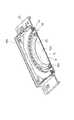
図1及び図2に示すように、硬貨の真偽判別に利用される刻印読取り装置1は、樹脂からなる筐体10を有しており、この筐体10の蓋部10aの一部に設けられた開口部11を塞ぐように、筐体10の蓋部10aには、サファイアガラス等で形成された防塵ガラス板12が接着剤を介して嵌め込み固定されている。この防塵ガラス板12のうちで、後述するライトガイド22で囲まれた領域が撮像部位Sとして画成され、この撮像部位S上で被写体としての硬貨(例えば、500円硬貨)C(図6参照)が撮像される。 As shown in FIGS. 1 and 2, a
硬貨Cの撮像にあたって、防塵ガラス板12の表面に沿って硬貨Cが摺動するので、刻印読取り装置1へ硬貨Cを連続供給は、硬貨搬送装置(図示せず)によって行われる。この硬貨搬送装置は、防振ガラス板12の延長上に配置された搬送テーブルと、モータ駆動する前後のプーリに架け渡された無端ベルトとで硬貨Cを挟み込みながら、硬貨Cは、硬貨ストッカから防塵ガラス板12上の撮像部位Sまで、図6の矢印A方向に自動搬送される。When the coin C is imaged, the coin C slides along the surface of the dust-
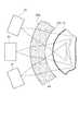
さらに、筐体10の内部には、防塵ガラス板12の内面12aに近接配置された照明手段20が収容されている。この照明手段20によって、撮像部位S内の硬貨Cを照らし出している。この硬貨Cは、視野角の広い大視野用の結像レンズ31とエリア型CCD32とを備えた大視野用の第1の撮像部30と、視野角の狭い小視野用の結像レンズ41とエリア型CCD42とを備えた小視野用の第2の撮像部40とによって撮像される。 Furthermore, the illumination means 20 disposed close to the
大視野用の第1の撮像部30は、撮像部位Sの中心を通る第1の撮像軸線L上に位置し、小視野用の第2の撮像部40は、第1の撮像軸線Lから分岐した第2の撮像軸線L1上に位置する。撮像光路を90度曲げて分岐させるにあたっては、ハーフミラー50が利用され、硬貨Cで反射した光は、ハーフミラー50を透過して大視野用の第1の撮像部30内に入射すると共に、ハーフミラー50で反射して小視野用の第2の撮像部40内に入射する。 The
硬貨Cの全体を撮像する大視野用の第1の撮像部30と、硬貨Cの局所を撮像する小視野用の第2の撮像部40とを備えた刻印読取り装置1では、光路の切り換えのためにハーフミラー50が設けられているので、ハーフミラー50によって透過/反射光量の半減が引き起こされ、このことが、CCD32,42によって撮像された画像を著しく暗くし、刻印パターンの読取り精度の悪化を引き起こすことになる。このことにより、硬貨Cを可能な限り明るく照らし出しつつ、照明ムラを少なくする工夫が照明手段20に必要となる。 In the marking
そこで、図3〜図5に示すように、照明手段20は、撮像部位Sを囲むようにして環状に配置されると共に、撮像部位Sを通る撮像軸線Lに向けて光を出射する36個の面実装型LED21と、LED21から出射した光を撮像部位Sに指向させる環状のライトガイド22とからなる。赤外光を発する各LED21は、回路基板23上で等間隔に配置されると共に、撮像軸線Lを中心にして環状に整列されている。各LED21は、筐体10の蓋部10aと回路基板23とで挟まれるようにして、撮像部位Sの径方向における外方に配置されている。 Therefore, as shown in FIGS. 3 to 5, the illumination means 20 is arranged in an annular shape so as to surround the imaging region S, and 36 surface mounts emit light toward the imaging axis L passing through the imaging region S. The
各LED21の内方には、アクリル樹脂からなる環状のライトガイド22が配置され、このライトガイド22は、環状に配置されたLED21によって囲まれるように配置されている。すなわち、ライトガイド22は、撮像軸線Lを中心にした環状に形成されると共に、LED21の配列に対して同心的に配置されている。そして、このライトガイド22の環状の接地面22cは、防塵ガラス板12の裏面12aに接着固定され、ライトガイド22の内周で撮像部位Sの領域が画成される。 An
図6及び図7に示すように、ライトガイド22は、撮像部位Sを通る撮像軸線Lに沿って延在する平面上において、各LED21の光源21aから入射した光が撮像部位Sに向けて平行光として出射する形状を有している。そして、LED21の光源21aから出射された拡散光を平行光として出射させつつ、硬貨Cの表面に対して角度のついた光を出射させるために、ライトガイド22のLED21側(外側)の入射面22aは、外方に膨出する湾曲面として形成され、ライトガイド22の撮像部位S側(内側)の出射面22bは、撮像部位Sの中心を通る撮像軸線Lに直交する平面に対して鈍角をなす傾斜面として形成されている。 As shown in FIGS. 6 and 7, in the
例えば、屈折率1.5のアクリル樹脂で形成されたライトガイド22を利用して、硬貨Cに対する平行光の出射角度αを15度に設定する場合、スネルの法則により、ライトガイド22の出射面22bの傾斜角度βは、115.85度である。そして、ライトガイド22から出射する光を浅い角度で刻印に照射すると、撮像結果において、エッジが強調された刻印を画像上で明確に浮き立たせることができる。そこで、検証の結果、平行光の出射角度αは、略1度〜略15度が最適であり、このときのライトガイド22の出射面22bの傾斜角度βは、略92度〜略116度である。 For example, when the
このように構成された照明手段20を利用することで、LED21からの光が平行光として被写体に照射されるので、LED21から出射された光を最大限利用することができ、照明ムラの発生低減にも寄与する。そして、大視野用の第1の撮像部30により硬貨Cの全体を撮像すること並びに小視野用の第2の撮像部40により硬貨Cの局所を撮像することを可能にし、読取り時において刻印パターンの読取り精度を向上させることができる。 By using the illumination means 20 configured in this way, the light from the
照明手段20の各LED21を点灯させる場合、到来センサが利用され、到来センサからの信号に基づいて、LED21が短時間フラッシュ点灯し、大視野用の第1の撮像部30のCCD32によって硬貨Cの全体を撮像し、小視野用の第2の撮像部40のCCD42によって硬貨Cの局所を撮像する。これら撮像は同時に行われ、その画像データは、画像処理装置に転送されて、パターンマッチングを行った後に硬貨Cの真偽判別を行う。このように、硬貨Cの全体と局所を鑑別することにより、硬貨Cの真偽判別の精度を向上させることができる。 When each
本発明は、前述した実施形態に限定されないことは言うまでもない。例えば、被写体として硬貨に限らず、メダルやカード等であってもよい。 It goes without saying that the present invention is not limited to the embodiment described above. For example, the subject is not limited to coins but may be medals or cards.
1…刻印読取り装置、21…LED、22…ライトガイド、22a…入射面、22b…出射面、30…第1の撮像部、40…第2の撮像部、50…ハーフミラー、S…撮像部位、C…硬貨(被写体)、L…撮像軸線、α…平行光の出射角度、β…ライトガイドの傾斜角度。
DESCRIPTION OF
Claims (3)
Translated fromJapanese前記撮像部位を囲むようにして環状に配置されると共に、前記撮像部位を通る撮像軸線に向けて光を出射する複数のLEDと、
環状に配置された前記LEDによって囲まれるように配置されると共に、前記撮像部位を通る前記撮像軸線に沿って延在する平面上において、前記LEDから入射した光が前記撮像部位に向けて平行光として出射する形状をもった環状のライトガイドと、
前記被写体で反射した光が透過及び反射するハーフミラーと、
前記ハーフミラーを透過した光を撮像する大視野用の第1の撮像部と、
前記ハーフミラーで反射した光を撮像する小視野用の第2の撮像部とを備えたことを特徴とする刻印読取り装置。In the marking reading device for reading the marking of the subject by illuminating the subject arranged at the imaging site with light,
A plurality of LEDs arranged in an annular shape so as to surround the imaging region, and emitting light toward an imaging axis passing through the imaging region;
On the plane extending along the imaging axis passing through the imaging part and arranged so as to be surrounded by the annularly arranged LEDs, the light incident from the LED is parallel light toward the imaging part An annular light guide with a shape that emits as
A half mirror that transmits and reflects light reflected by the subject;
A first imaging unit for a large visual field for imaging light transmitted through the half mirror;
A marking reading device comprising: a second imaging unit for a small field of view that images the light reflected by the half mirror.
The emission angle of the parallel light emitted from the light guide is approximately 1 degree to approximately 15 degrees with respect to a plane orthogonal to the imaging axis passing through the imaging part. Stamp reader.
Priority Applications (1)
| Application Number | Priority Date | Filing Date | Title |
|---|---|---|---|
| JP2005372977AJP2007172547A (en) | 2005-12-26 | 2005-12-26 | Engraved mark reader |
Applications Claiming Priority (1)
| Application Number | Priority Date | Filing Date | Title |
|---|---|---|---|
| JP2005372977AJP2007172547A (en) | 2005-12-26 | 2005-12-26 | Engraved mark reader |
Publications (1)
| Publication Number | Publication Date |
|---|---|
| JP2007172547Atrue JP2007172547A (en) | 2007-07-05 |
Family
ID=38298985
Family Applications (1)
| Application Number | Title | Priority Date | Filing Date |
|---|---|---|---|
| JP2005372977APendingJP2007172547A (en) | 2005-12-26 | 2005-12-26 | Engraved mark reader |
Country Status (1)
| Country | Link |
|---|---|
| JP (1) | JP2007172547A (en) |
Cited By (3)
| Publication number | Priority date | Publication date | Assignee | Title |
|---|---|---|---|---|
| WO2010112950A1 (en)* | 2009-03-31 | 2010-10-07 | Sicpa Holding Sa | Annular light guide illuminator and optical scanner |
| CN102332187A (en)* | 2011-09-30 | 2012-01-25 | 中钞长城金融设备控股有限公司 | Coin detection equipment |
| CN103136846A (en)* | 2013-02-06 | 2013-06-05 | 江苏科思机电工程有限公司 | One-time imaging detection illumination device |
- 2005
- 2005-12-26JPJP2005372977Apatent/JP2007172547A/enactivePending
Cited By (8)
| Publication number | Priority date | Publication date | Assignee | Title |
|---|---|---|---|---|
| WO2010112950A1 (en)* | 2009-03-31 | 2010-10-07 | Sicpa Holding Sa | Annular light guide illuminator and optical scanner |
| JP2012522302A (en)* | 2009-03-31 | 2012-09-20 | シクパ ホールディング エスアー | Annular light guide illuminator and optical scanner |
| US8894260B2 (en) | 2009-03-31 | 2014-11-25 | Sicpa Holding Sa | Annular light guide illuminator and optical scanner |
| CN102369537B (en)* | 2009-03-31 | 2015-01-21 | 锡克拜控股有限公司 | Annular light guide illuminator and optical scanner |
| EA022315B1 (en)* | 2009-03-31 | 2015-12-30 | Сикпа Холдинг Са | Annular light guide illuminator and optical scanner |
| KR101604160B1 (en) | 2009-03-31 | 2016-03-16 | 시크파 홀딩 에스에이 | Annular Light Guide Illuminator and Optical Scanner |
| CN102332187A (en)* | 2011-09-30 | 2012-01-25 | 中钞长城金融设备控股有限公司 | Coin detection equipment |
| CN103136846A (en)* | 2013-02-06 | 2013-06-05 | 江苏科思机电工程有限公司 | One-time imaging detection illumination device |
Similar Documents
| Publication | Publication Date | Title |
|---|---|---|
| US9332148B2 (en) | Reading device | |
| EP2365688B1 (en) | Image reading device | |
| US8310737B2 (en) | Image reading apparatus | |
| US9672399B2 (en) | Diffuse bright field illumination system for a barcode reader | |
| US20150021400A1 (en) | Barcode reader having multiple illumination systems and multiple sets of imaging optics | |
| TW200842347A (en) | Pattern checking device and pattern checking mehtod | |
| JP2012212221A (en) | Imaging unit and coin identification device | |
| US8864034B1 (en) | Barcode reader having multiple illumination systems and multiple sets of imaging optics | |
| JP2007172547A (en) | Engraved mark reader | |
| JP5796615B2 (en) | Image input device | |
| JP4216667B2 (en) | Imaging device | |
| JP5230327B2 (en) | Stamp reader | |
| JP4401943B2 (en) | Stamp reader | |
| JP4264169B2 (en) | Stamp reader | |
| JP6823484B2 (en) | Image collection device, coin-like medium processing machine and image collection method | |
| JP2005099939A (en) | Carved seal reader | |
| JP4401947B2 (en) | Stamp reader | |
| JP3716036B2 (en) | Stamp reader | |
| JP4460924B2 (en) | Image reading device | |
| JPH096942A (en) | Marking reader | |
| JP7089886B2 (en) | Identification device | |
| JP5117468B2 (en) | Imaging device | |
| JP4334240B2 (en) | Recognition device | |
| JPH08202916A (en) | Illuminator in surface pattern reader | |
| JPH09282512A (en) | Marking reader |