JP2007171330A - Photomask for color filter, color filter using the same, manufacturing method thereof, and liquid crystal display element - Google Patents
Photomask for color filter, color filter using the same, manufacturing method thereof, and liquid crystal display elementDownload PDFInfo
- Publication number
- JP2007171330A JP2007171330AJP2005365946AJP2005365946AJP2007171330AJP 2007171330 AJP2007171330 AJP 2007171330AJP 2005365946 AJP2005365946 AJP 2005365946AJP 2005365946 AJP2005365946 AJP 2005365946AJP 2007171330 AJP2007171330 AJP 2007171330A
- Authority
- JP
- Japan
- Prior art keywords
- color filter
- photomask
- light
- layer
- strip
- Prior art date
- Legal status (The legal status is an assumption and is not a legal conclusion. Google has not performed a legal analysis and makes no representation as to the accuracy of the status listed.)
- Pending
Links
Images

Landscapes
- Optical Filters (AREA)
- Preparing Plates And Mask In Photomechanical Process (AREA)
- Liquid Crystal (AREA)
Abstract
Translated fromJapaneseDescription
Translated fromJapanese本発明は、フォトリソグラフィ法によってガラス基板上にカラーフィルタの感光性組成物層を形成する際に用いて好適なカラーフィルタ用フォトマスク、それを用いた液晶表示装置用カラーフィルタの形成方法、カラーフィルタ基板及びそのカラーフィルタを備えた液晶表示装置に関するものであり、一括露光法によってフォトマスクを介し基板に近接露光を行っても、該感光性組成物層に6μm以下の幅の微細な所望の帯状開口部を形成できるため、より高精細な半透過型液晶表示装置に関する。 The present invention relates to a photomask for a color filter suitable for use in forming a photosensitive composition layer of a color filter on a glass substrate by a photolithography method, a method for forming a color filter for a liquid crystal display device using the photomask, and a color The present invention relates to a filter substrate and a liquid crystal display device including the color filter. Even if proximity exposure is performed on the substrate through a photomask by a batch exposure method, the photosensitive composition layer has a fine desired width of 6 μm or less. The present invention relates to a higher-definition transflective liquid crystal display device because a band-shaped opening can be formed.
半透過型液晶表示装置(半透過型LCD)は、屋内など外光が少なく比較的暗い場所ではバックライトなどからの発光装置の光を透過して表示する透過表示部と、屋外など十分に外光が得られる場所ではアレイ側に備えられた反射板により外光を反射させて表示する反射表示部を備えた方式であり、屋外での使用が多いモバイル機器の表示装置として広く採用されている。 A transflective liquid crystal display device (semi-transmissive LCD) has a transmissive display part that transmits light from the light emitting device from a backlight or the like in a relatively dark place where there is little outside light, such as indoors, and the outside, such as outdoors. In a place where light can be obtained, it is a system with a reflective display unit that reflects external light by a reflector provided on the array side and is widely used as a display device for mobile devices that are often used outdoors. .
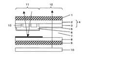
半透過型LCDの液晶セルは、図5に示すように、カラーフィルタ基板4と液晶駆動用の画素電極や回路等を形成した基板(アレイ基板)7とで液晶6を挟持した構造であり、カラーフィルタ基板には、基板上に複数の感光性着色組成物層3が形成されている。前記感光性着色組成物層3は、層内を通過する光を所定の色に着色するもので、透明樹脂中に、着色顔料等の着色剤を分散させたものが一般的である(以下感光性着色組成物層をRGB材料層と記す)。半透過型LCD用カラーフィルタ基板では、1画素中に、透過表示部用のRGB材料層と、反射表示部用のRGB材料層とを有しているが、アレイ側に反射板を備え、半透過型LCD内に入射する外光線を反射させて表示する前記反射表示部においては、カラーフィルタ表示面から入射した外光線はカラーフィルタを構成するRGB材料層を2回通過することから、反射表示部の画素表示が暗くなる、透過表示部との色純度が合わない等の問題が生じていた。 As shown in FIG. 5, the liquid crystal cell of the transflective LCD has a structure in which a
上記の問題を解決する方法として、従来の技術では、以下の方法が提案されている。 As a method for solving the above problem, the following methods have been proposed in the prior art.
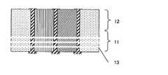
すなわち、図5に示すように、同じ着色材料を用いて、透過表示部12と反射表示部11に同時にRGB材料層を塗布形成するが、反射表示部11のRGB材料層3の画素内にスルーホール13(感光性着色組成物層を形成しない貫通領域)をパターン形成し、高い透過率を備えたRGB材料層とする方法である。前記画素内のスルーホール13の形状は寸法管理が比較的行いやすい円パターン、又は、ストライプの帯状パターン等が広く用いられており、前記スルーホールを形成することで前記画素のカラー特性を調整する方法が一般的である。 That is, as shown in FIG. 5, an RGB material layer is applied and formed simultaneously on the
次に、従来のスルーホール型の半透過型LCD用カラーフィルタの製造方法を説明する。 Next, a method for manufacturing a conventional color filter for through-hole type transflective LCD will be described.
図6は、従来のスルーホール型の半透過型LCD用カラーフィルタの一例を示す製造工程図である。まず、所定の材質で、片側全表面に金属薄膜(遮光膜用)を具備したカラーフィルタ用の基板14を工程に投入する。 FIG. 6 is a manufacturing process diagram showing an example of a conventional through-hole type transflective LCD color filter. First, a
(a)最初に、前記基板に所定のパターンとした遮光膜15を形成する。すなわち、まず前記金属薄膜上に感光性のレジスト樹脂を塗布しレジスト層を形成する。予め準備した
遮光膜用パターンを備えた遮光膜用フォトマスクを用いて所定光源を照射露光して、前記レジスト層に遮光膜パターンを転写後、所定の現像処理をする。次に、遮光膜用パターンを備えた前記レジスト層をマスクとして露出した前記金属薄膜部をエッチング処理し、遮光膜15のパターンを形成する。(図6(c)参照)ここで遮光膜15間の各開口部が各々1画素となる。(A) First, a
(b)前記画素内にRGB材料層を形成する。すなわち、前記基板上の前記遮光膜から開口部まで全面に1色目の着色材料、例えば感光性樹脂中にR(赤)色顔料を分散させたR材料レジストを所定の方法で塗布し基板全面にR材料レジストの塗布層を形成する。予め準備したR層用パターンを備えたR層フォトマスクを用いて、前記塗布層に所定光源を照射露光して、前記塗布層にR層パターンを転写後、所定の現像処理を行ってR層16のパターンを形成する。(図6(e)参照)前記R層フォトマスクはR層用パターンを備えている。該パターンは所定のスルーホールパターンを具備した反射表示部の画素パターンと、透過表示部の画素パターンである。 (B) An RGB material layer is formed in the pixel. That is, a coloring material of the first color, for example, an R material resist in which an R (red) color pigment is dispersed in a photosensitive resin is applied to the entire surface from the light shielding film to the opening on the substrate by a predetermined method. A coating layer of R material resist is formed. Using an R layer photomask having an R layer pattern prepared in advance, the coating layer is exposed to light by irradiating a predetermined light source, the R layer pattern is transferred to the coating layer, and then a predetermined development process is performed. Sixteen patterns are formed. (See FIG. 6E.) The R layer photomask includes an R layer pattern. The patterns are a pixel pattern of a reflective display unit having a predetermined through-hole pattern and a pixel pattern of a transmissive display unit.
(c)次いで、2色目のRGB材料層を形成する。すなわち、前記基板上の遮光膜から開口部及びR層の上全面に2色目の着色材料、例えば感光性樹脂中にG色顔料を分散させたG(緑)材料レジストを所定の方法で塗布し基板全面にG材料レジストの塗布層を形成する。予め準備したG層用スルーホールパターンを備えた反射表示部用パターンと、透過表示部用パターンを有するG層フォトマスクを用いて、前記塗布層に所定光源を照射露光して、前記塗布層にG層パターンを転写後、所定の現像処理を行ってG層17のパターンを形成する。(図6(f)参照)前記G層は前記R層を形成した画素の隣の画素に形成されている。 (C) Next, an RGB material layer of the second color is formed. That is, a second coloring material, for example, a G (green) material resist in which a G color pigment is dispersed in a photosensitive resin is applied from the light shielding film on the substrate to the opening and the entire surface of the R layer by a predetermined method. A coating layer of G material resist is formed on the entire surface of the substrate. Using a G layer photomask having a reflective display portion pattern having a G layer through-hole pattern prepared in advance and a transmissive display portion pattern, the coating layer is irradiated with a predetermined light source and exposed to the coating layer. After transferring the G layer pattern, a predetermined development process is performed to form a pattern of the
(d)次いで、3色目のRGB材料層を形成する工程は、前記基板上の遮光膜から開口部及びR層、G層の上全面に3色目の着色材料、例えば感光性樹脂中にB(青)色顔料を分散させたB材料レジストを所定の方法で塗布し基板全面にB材料レジストの塗布層を形成する。予め準備したB層用スルーホールパターンを備えた反射表示部用パターンと、透過表示部用パターンとを有するB層フォトマスクを用いて、前記塗布層に所定光源を照射露光して、前記塗布層にB層パターンを転写後、所定の現像処理を行ってB層18のパターンを形成する。(図6(g)参照)前記B層は前記R層、及びG層を形成した画素の隣の画素に形成されている。すなわち、R層16、G層17、B層18の順番に配列するRGB材料層3を形成する。反射表示部の前記RGB材料層はスルーホール13を形成した画素である(図6(h)参照)。 (D) Next, in the step of forming the RGB material layer of the third color, the color material of the third color, for example, B (in the photosensitive resin) is formed on the entire surface of the opening, the R layer, and the G layer from the light shielding film on the substrate. Blue) A B material resist in which a color pigment is dispersed is applied by a predetermined method to form a B material resist coating layer on the entire surface of the substrate. Using a B layer photomask having a reflective display portion pattern having a B layer through-hole pattern prepared in advance and a transmissive display portion pattern, the coating layer is irradiated with a predetermined light source and exposed to light. After the transfer of the B layer pattern, a predetermined development process is performed to form the
(e)次に、基板上の全面に透明樹脂層よりなるOC層6を塗布形成し、平坦とする(図5参照)。 (E) Next, an
(f)前記画素内に透明電極5を形成する。前記基板上の遮光膜からRGB材料まで全面に所定の成膜装置、所定の方法によって導電性の材料からなる透明薄膜を形成する。なお、治具等を用いて成膜するため、前記透明薄膜は所定の形状からなる透明電極5として形成されている(図5参照)。 (F) A
上記の処理工程後、基板全体を洗浄して、スルーホール型の半透過型LCD用カラーフィルタが完成する。 After the above processing steps, the entire substrate is cleaned to complete a through-hole type transflective LCD color filter.
ここで、上述したように、スルーホール型の半透過型LCD用カラーフィルタの製造方法にはフォトリソグラフィ法が用いられるのが一般的であり、生産のスループット・製造装置の初期費用の観点からプロキシミティーアライナーによる一括・近接露光方式で感光性組成物層のパターン形成が行なわれている場合がほとんどである。すなわち、あらかじ
め遮光層となる金属膜のパターンを具備した石英マスクとカラーフィルタ用基板とが数十〜数百μmの間隔で近接し、該石英マスクを介してUV照射することで該カラーフィルタ基板に塗布された感光性組成物の光硬化を行っている。UV照射用露光光源は、一般的に高圧水銀ランプが用いられている。その主たる露光波長は、302nm、312nm、334nm、365nm、405nm等が挙げられる。これら露光波長に感光する光重合開始剤および光重合性モノマーを適量配合する事により、感光組成物を調整している。一括・近接露光方式では、生産のスループットが他方式に比べ高いことや製造装置の初期費用が安く抑えられるなどの利点がある反面、UV光の回折の影響や、石英マスクとカラーフィルタ基板とのギャップ量の影響を受けやすいため、従来のカラーフィルタ用フォトマスク及びカラーフィルタ製造方法では幅6μm以下のような微細な帯状開口部の形成が困難であるなどの課題があった。Here, as described above, a photolithography method is generally used as a method for manufacturing a color filter for a through-hole type transflective LCD, and the proxy is used from the viewpoint of production throughput and initial cost of a manufacturing apparatus. In most cases, the photosensitive composition layer is patterned by a batch / proximity exposure method using a miti aligner. That is, a quartz mask provided with a metal film pattern serving as a light shielding layer in advance and a color filter substrate are close to each other at intervals of several tens to several hundreds of μm, and the color filter substrate is irradiated with UV through the quartz mask. The photo-curing of the photosensitive composition applied to is carried out. A high pressure mercury lamp is generally used as an exposure light source for UV irradiation. The main exposure wavelengths include 302 nm, 312 nm, 334 nm, 365 nm, 405 nm, and the like. The photosensitive composition is prepared by blending appropriate amounts of a photopolymerization initiator and a photopolymerizable monomer that are sensitive to the exposure wavelength. While the batch / proximity exposure method has advantages such as higher production throughput and lower initial cost of manufacturing equipment, it has the advantage of UV light diffraction and the relationship between the quartz mask and the color filter substrate. Since it is easily affected by the gap amount, the conventional color filter photomask and color filter manufacturing method have problems such as difficulty in forming a fine band-shaped opening having a width of 6 μm or less.
携帯電話やデジタルスチルカメラなどのモバイル機器の表示装置として半透過型LCDが広く採用されているが、近年、その表示装置の高精細化が進むにつれて、半透過型LCD用カラーフィルタの反射表示部のスルーホールパターンの高精細化も必要となってきている。例えば2.4インチ型の携帯電話で従来の解像度がQVGA(320×240画素)であったものが、VGA(640×480画素)の解像度となった場合、RGB材料層の1画素の幅が約75μmから約25μmにまで狭くなることになる。従って25μm幅の画素内に形成される帯状開口部パターンもより小さいものである必要がある。 Transflective LCDs are widely used as display devices for mobile devices such as mobile phones and digital still cameras. However, in recent years, as the display devices have become higher definition, the reflective display portion of the color filter for transflective LCDs. High definition of through hole patterns is also required. For example, when a 2.4 inch mobile phone has a conventional resolution of QVGA (320 × 240 pixels) but a resolution of VGA (640 × 480 pixels), the width of one pixel of the RGB material layer is It will be narrowed from about 75 μm to about 25 μm. Therefore, the band-shaped opening pattern formed in a pixel having a width of 25 μm needs to be smaller.
最近では、近接露光方式以外に、ミラープロジェクションやレンズ集光などによる等倍投影方式のカラーフィルタ製造用露光装置の実用化が進んでおり、回折の影響やギャップ量の影響を受けずにパターンを形成することが可能となってきている。 Recently, in addition to the proximity exposure method, an exposure device for manufacturing color filters of the same size projection method using mirror projection or lens condensing has been put into practical use, and a pattern can be formed without being influenced by diffraction or gap amount. It has become possible to form.
また、近接露光方式において、解像限界以上の大きさのマスクパターンを有する露光用マスクとネガ型着色感材を塗布した基板の相対位置をずらして露光を行うことで解像限界以下の幅の狭い開口部を形成する方法が提案されている(特許文献1)。 In the proximity exposure method, exposure is performed by shifting the relative position of the exposure mask having a mask pattern larger than the resolution limit and the substrate on which the negative coloring photosensitive material is applied. A method for forming a narrow opening has been proposed (Patent Document 1).
これら露光装置に特別な機能を要する方法では、通常の近接露光方式と比較して露光装置の初期費用が嵩む、生産のスループットが低下するなどの課題があり、カラーフィルタ基板のコストダウンにつながらない場合が多い。 When these exposure apparatuses require special functions, there are problems such as an increase in the initial cost of the exposure apparatus and a decrease in production throughput compared to the normal proximity exposure method, which does not lead to cost reduction of the color filter substrate. There are many.
一方、近接露光方式での回折効果を利用して、露光用マスクの開口パターンの形状、方向が忠実に転写されない転写条件で用いて好適なフォトマスクおよびそれを用いた露光方式が提案されているが、この方法は解像できる形状が円形であり、かつ円形上の開口の径が3μm〜12μmの場合に効果的であり本発明における問題を解決できるものではなかった(特許文献2)。 On the other hand, a photomask suitable for use under transfer conditions in which the shape and direction of the opening pattern of the exposure mask are not faithfully transferred using the diffraction effect in the proximity exposure method and an exposure method using the photomask have been proposed. However, this method is effective when the resolvable shape is a circle and the diameter of the opening on the circle is 3 μm to 12 μm, and does not solve the problem in the present invention (Patent Document 2).
また、カラーフィルタ用フォトマスクに特徴を持たせることで、感光性組成物層に形成されるパターンの解像性を向上させる提案もいくつかなされているが、やはりこれらの提案も本発明における問題を解決できるものではなかった(特許文献3・4・5)。 In addition, some proposals have been made to improve the resolution of the pattern formed on the photosensitive composition layer by giving a characteristic to the photomask for the color filter. However, these proposals are also problems in the present invention. This cannot be solved (
特許文献等は以下の通りである。
本発明は、上記の問題を解決するためになされたものであり、フォトリソグラフィ法によってガラス基板上にカラーフィルタの感光性樹脂層を形成する際に、一括露光法によってフォトマスクを介し基板に近接露光を行っても、該感光性組成物層に6μm以下の幅の微細な所望の帯状開口部を形成することのできるカラーフィルタ用フォトマスク、およびこれを用いた液晶表示装置用カラーフィルタの形成方法を提供することを目的とする。 The present invention has been made to solve the above-described problems. When a photosensitive resin layer of a color filter is formed on a glass substrate by a photolithography method, it is close to the substrate through a photomask by a batch exposure method. A color filter photomask capable of forming a desired strip-shaped opening having a width of 6 μm or less in the photosensitive composition layer even after exposure, and formation of a color filter for a liquid crystal display device using the photomask It aims to provide a method.
本発明者らは鋭意検討した結果、感光性組成物層に6μm以下の幅の微細な所望の帯状の開口部を形成するための単位の遮光パターンとして、光透過部である開口領域中に光遮光部である複数の帯状の遮光パターンを設けたフォトマスクを用いることにより上記課題を解決し得ることを見出し、本発明を完成した。 As a result of intensive studies, the inventors of the present invention have made light in an opening region, which is a light transmitting portion, as a light shielding pattern of a unit for forming a fine desired strip-shaped opening having a width of 6 μm or less in the photosensitive composition layer. The present invention has been completed by finding that the above problem can be solved by using a photomask provided with a plurality of strip-shaped light shielding patterns which are light shielding portions.
本発明の請求項1に係る発明は、近接露光法を用いたフォトリソグラフィ法により、ネガ型フォトレジストを用いて矩形の感光性樹脂層を形成する際に使用するカラーフィルタ用フォトマスクであって、該感光性組成物層に所望の微細な帯状の開口部を形成するための単位の遮光パターンとして、光透過部である開口領域中に光遮光部である複数の帯状の遮光パターンを設けたことを特徴とする。 The invention according to claim 1 of the present invention is a photomask for a color filter used when forming a rectangular photosensitive resin layer using a negative photoresist by a photolithography method using a proximity exposure method. As a light shielding pattern of a unit for forming a desired fine strip-shaped opening in the photosensitive composition layer, a plurality of strip-shaped light shielding patterns as light shielding portions are provided in an opening region as a light transmitting portion. It is characterized by that.
本発明の請求項2に係る発明は、請求項1に記載のカラーフィルタ用フォトマスクにおいて、前記遮光パターンが、該感光性樹脂層に形成する所望の帯状の開口部の単位に対して、その帯方向の中心線を対称軸として2つの帯状の遮光パターンであることを特徴とする。 According to a second aspect of the present invention, in the photomask for color filter according to the first aspect, the light shielding pattern is formed with respect to a desired band-shaped opening unit formed in the photosensitive resin layer. The band-shaped light shielding pattern is characterized in that the center line in the band direction is an axis of symmetry.
本発明の請求項3に係る発明は、請求項2に記載のカラーフィルタ用フォトマスクにおいて、前記2つの帯状の遮光パターンが同一形状であることを特徴とする。 According to a third aspect of the present invention, in the photomask for color filter according to the second aspect, the two strip-shaped light shielding patterns have the same shape.
本発明の請求項4に係る発明は、請求項3に記載のカラーフィルタ用フォトマスクにおいて、前記2つの帯状の遮光パターンが、6μm以下の間隔をおいて離れて設けられていることを特徴とする。 According to a fourth aspect of the present invention, in the color filter photomask according to the third aspect, the two strip-shaped light shielding patterns are provided with an interval of 6 μm or less. To do.
本発明の請求項5に係る発明は、請求項1に記載のカラーフィルタ用フォトマスクにおいて、前記遮光パターンが、該感光性樹脂層に形成する所望の帯状の開口部の単位に対して、その帯方向の中心線を対称軸として3つの帯状の遮光パターンであることを特徴とする。 The invention according to
本発明の請求項6に係る発明は、カラーフィルタの製造方法が感光性組成物層に6μm以下の幅の微細な所望の帯状の開口部を形成するために、請求項1ないし5のいずれか1に記載のカラーフィルタ用フォトマスクを用いることを特徴とする。 The invention according to
本発明の請求項7に係る発明は、カラーフィルタが感光性組成物層に幅6μm以下の微細な帯状の開口部を有することを特徴とする。 The invention according to
本発明の請求項8に係る発明は、半透過型液晶表示装置が請求項7に記載のカラーフィルタを備えることを特徴とする。 According to an eighth aspect of the present invention, a transflective liquid crystal display device includes the color filter according to the seventh aspect.
以上詳述したように、本発明のカラーフィルタ用フォトマスクは、フォトリソグラフィ法によってガラス基板上にカラーフィルタの感光性樹脂層を形成する際に、一括露光法によってフォトマスクを介し基板に近接露光を行っても、該感光性樹脂層に6μm以下の幅
の微細な所望の帯状開口部を形成することができ、より高精細な半透過型液晶表示装置を提供することができる。As described in detail above, the color filter photomask of the present invention is a proximity exposure to the substrate through the photomask when the photosensitive resin layer of the color filter is formed on the glass substrate by photolithography. Even if it performs, a desired strip-shaped opening having a width of 6 μm or less can be formed in the photosensitive resin layer, and a higher-definition transflective liquid crystal display device can be provided.
本発明を一実施の形態に基づいて以下に説明する。 The present invention will be described below based on one embodiment.
[フォトマスク]
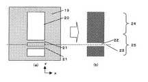
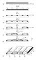
図1(a)は、本発明によるカラーフィルタ用フォトマスクの一実施例のパターンの一部を拡大して示す平面図である。このカラーフィルタ用フォトマスクは、着色画素を形成するためのものであり、また、着色画素を形成するフォトレジストとしてネガ型感光性着色組成物を用いた際のものである。また、図1(b)は、図1(a)に示すフォトマスクを用いて形成された着色画素を拡大して示す平面図である。[Photomask]
FIG. 1A is an enlarged plan view showing a part of a pattern of an embodiment of a color filter photomask according to the present invention. This color filter photomask is used for forming colored pixels, and is obtained when a negative photosensitive coloring composition is used as a photoresist for forming colored pixels. FIG. 1B is an enlarged plan view showing colored pixels formed using the photomask shown in FIG.
図1(a)に示すように、このフォトマスクは光透過部20と遮光部19で構成され、光透過部20はx方向の長さ約25μm、y方向の長さ約75μm程度の矩形で、所望する着色画素の形状となっている。 As shown in FIG. 1A, the photomask is composed of a
矩形の光透過部20の反射型表示部25には帯状遮光パターン21が2つ設けられており、この帯状遮光パターン21は、図1(b)に示す所望の着色画素の帯状開口部22の帯方向の中心線を対称軸としている。 Two strip-shaped
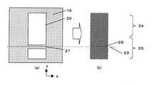
図2(a)は、本発明によるカラーフィルタ用フォトマスクの2つめの実施例のパターンの一部を拡大して示す平面図である。また、図2(b)は、図2(a)に示すフォトマスクを用いて形成された着色画素を拡大して示す平面図である。 FIG. 2A is an enlarged plan view showing a part of the pattern of the second embodiment of the color filter photomask according to the present invention. FIG. 2B is an enlarged plan view showing the colored pixels formed using the photomask shown in FIG.
図2(a)は図1(a)と同様に、光透過部20と遮光部19で構成され、光透過部20はx方向の長さ約25μm、y方向の長さ約75μm程度の矩形で、所望する着色画素の形状となっている。 2A is composed of a
矩形の光透過部20の反射型表示部25には帯状遮光パターン21が3つ設けられており、この帯状遮光パターン21は、図2(b)に示す所望の着色画素の帯状開口部22の帯方向の中心線を対称軸としている。 Three reflective light-shielding
図3(a)は、本発明によるカラーフィルタ用フォトマスクを用いない比較例のパターンの一部を拡大して示す平面図である。また、図3(b)は、図3(a)に示すフォトマスクを用いて形成された着色画素を拡大して示す平面図である。 FIG. 3A is an enlarged plan view showing a part of a pattern of a comparative example that does not use the color filter photomask according to the present invention. FIG. 3B is an enlarged plan view showing colored pixels formed using the photomask shown in FIG.
図3(a)に示す、矩形の光透過部20の反射型表示部25には帯状遮光パターン21が1つ設けられており、本来であればこの帯状遮光パターン21は、露光によって忠実に再現され図1(b)や図1(a)に示す所望の着色画素の帯状開口部22を形成しなければならないが、近接露光の回折効果により微細な遮光部に回り込んだ露光光によって遮光部の働きをしなくなった結果、図3(b)のようにパターンは解像されない。 A single band-shaped
図1(a)および図2(a)に示すフォトマスクの光透過部20としてはx方向の長さが約15μmから80μm、y方向の長さ約45μmから240μm程度の矩形が多く用いられ、好ましくはx方向の長さが約15μmから30μm、y方向の長さ約45μmから90μm程度の矩形の場合に本発明のカラーフィルタの製造方法が有効となる。 As the
図1(a)に示す、矩形の光透過部20の反射型表示部25に設けられた帯状遮光パターン21は、y方向の長さが約1μmから6μm程度の帯状遮光パターンが多く用いられ
、好ましくはy方向の長さが約1μmから3μm程度の帯状遮光パターンの場合に本発明のカラーフィルタの製造方法が有効となる。また2つの帯状遮光パターンの間隔はy方向の長さが約1μmから6μm程度であることが好ましい。The strip-shaped
図2(a)に示す、矩形の光透過部20の反射型表示部25に設けられた帯状遮光パターン21は、y方向の長さが約1μmから6μm程度の帯状遮光パターンが多く用いられ、好ましくはy方向の長さが約1μmから3μm程度の帯状遮光パターンの場合に本発明のカラーフィルタの製造方法が有効となる。また3つの帯状遮光パターンの間隔はy方向の長さが約1μmから6μm程度であることが好ましく、3つの帯状遮光パターンのy方向の長さは3つが等しくてもそれぞれ異なっていてもよい。 The strip-shaped
なお、本発明のカラーフィルタの製造方法において、上記フォトマスクを用いて形成される部材としては、上記着色部だけではなく、例えば遮光部や保護層等であってもよい。また、本発明においては、上記フォトマスクを用いて部材を形成する工程以外に、必要に応じて他の工程を有していてもよい。このような工程や、本発明のカラーフィルタに用いられる各部材の材料等については、一般的なカラーフィルタに用いられる材料や製造方法等と同様のものを用いることができる。ここでは代表的な感光性組成物について以下に説明する。 In the method for producing a color filter of the present invention, the member formed using the photomask is not limited to the colored portion, but may be, for example, a light shielding portion or a protective layer. Moreover, in this invention, you may have another process as needed other than the process of forming a member using the said photomask. With respect to such a process and the material of each member used for the color filter of the present invention, the same materials and manufacturing methods used for general color filters can be used. Here, typical photosensitive compositions will be described below.
[感光性組成物]
本発明に用いて好適な感光性組成物は、光重合性モノマー、非感光性樹脂及び/又は感光性樹脂、重合開始剤、及び溶剤を含有してなり、これらはUV露光、DeepUV露光のいずれの硬化方法を用いてもよい。[Photosensitive composition]
A photosensitive composition suitable for use in the present invention comprises a photopolymerizable monomer, a non-photosensitive resin and / or a photosensitive resin, a polymerization initiator, and a solvent, which can be used for either UV exposure or Deep UV exposure. The curing method may be used.
(光重合性モノマー)
本発明に用いて好適な感光性組成物には光重合性モノマーが配合される。前記光重合性モノマーには、水酸基を有する(メタ)アクリレートに多官能イソシアネートを反応させて得られる(メタ)アクリロイル基を有する多官能ウレタンアクリレートを用いることが好ましい。なお、水酸基を有する(メタ)アクリレートと多官能イソシアネートとの組み合わせは任意であり、特に限定されるものではない。また、1種の多官能ウレタンアクリレートを単独で用いても良いし、2種以上を組み合わせて用いることもできる。(Photopolymerizable monomer)
A photopolymerizable monomer is blended in the photosensitive composition suitable for use in the present invention. As the photopolymerizable monomer, it is preferable to use a polyfunctional urethane acrylate having a (meth) acryloyl group obtained by reacting a polyfunctional isocyanate with a (meth) acrylate having a hydroxyl group. The combination of the (meth) acrylate having a hydroxyl group and the polyfunctional isocyanate is arbitrary and is not particularly limited. Moreover, one type of polyfunctional urethane acrylate may be used alone, or two or more types may be used in combination.
(非感光性樹脂及び/又は感光性樹脂)
本発明に用いて好適な感光性組成物には、非感光性樹脂及び/又は感光性樹脂が配合される。現在、環境問題の観点から、現像液として有機溶剤は殆ど使われなくなり、アルカリ現像が主流となっているが、アルカリ現像を採用する場合、アルカリ可溶型非感光性樹脂を含有させることが好ましい。ここで、アルカリ可溶型非感光性樹脂とは、アルカリ水溶液に溶解性を有すると共に、ラジカル架橋性を有しない樹脂のことを意味しており、例えば、カルボキシル基、スルホン基等の酸性官能基を有する質量平均分子量1000〜50万、好ましくは5000〜10万の樹脂が挙げられる。具体的には、アクリル樹脂、α−オレフィン/(無水)マレイン酸共重体、スチレン/(無水)マレイン酸共重合体、スチレン/スチレンスルホン酸共重合体、エチレン/(メタ)アクリル酸共重合体、イソブチレン/(無水)マレイン酸共重合体等が挙げられる。中でも、アクリル樹脂、α−オレフィン/(無水)マレイン酸共重合体、スチレン/スチレンスルホン酸共重合体から選ばれる少なくとも1種の樹脂が好ましい。これらの中でも特に、アクリル樹脂は、耐熱性、透明性が高いことから、好適に用いられる。(Non-photosensitive resin and / or photosensitive resin)
In the photosensitive composition suitable for use in the present invention, a non-photosensitive resin and / or a photosensitive resin is blended. At present, from the viewpoint of environmental problems, organic solvents are hardly used as a developer, and alkali development has become the mainstream, but when employing alkali development, it is preferable to include an alkali-soluble non-photosensitive resin. . Here, the alkali-soluble non-photosensitive resin means a resin that is soluble in an alkaline aqueous solution and does not have radical crosslinkability. For example, an acidic functional group such as a carboxyl group or a sulfone group. And a resin having a mass average molecular weight of 1,000 to 500,000, preferably 5,000 to 100,000. Specifically, acrylic resin, α-olefin / (anhydrous) maleic acid copolymer, styrene / (anhydrous) maleic acid copolymer, styrene / styrene sulfonic acid copolymer, ethylene / (meth) acrylic acid copolymer And isobutylene / (anhydrous) maleic acid copolymer. Among these, at least one resin selected from acrylic resins, α-olefin / (anhydrous) maleic acid copolymers, and styrene / styrene sulfonic acid copolymers is preferable. Among these, acrylic resins are preferably used because of their high heat resistance and transparency.
(顔料)
感光性組成物層がカラーフィルタの着色層や遮光層用である場合、さらに、顔料を含有させる必要がある。着色層の形成用としては感光性組成物に公知の顔料を用いることができ
る。顔料の配合量は特に限定されるものではないが、組成物の総量100質量%に対して、1〜20質量%程度であることが好ましい。また、カラーフィルタの分光調整等のために、複数の顔料を組み合わせて用いることもできる。(Pigment)
When the photosensitive composition layer is for a colored layer or a light shielding layer of a color filter, it is necessary to further contain a pigment. For forming the colored layer, known pigments can be used in the photosensitive composition. Although the compounding quantity of a pigment is not specifically limited, It is preferable that it is about 1-20 mass% with respect to 100 mass% of total amounts of a composition. Also, a plurality of pigments can be used in combination for spectral adjustment of the color filter.
また、上記有機顔料と組み合わせて、彩度と明度のバランスを取りつつ良好な塗布性、感度、現像性等を確保するために、無機顔料を組み合わせて用いることも可能である。無機顔料としては、黄色鉛、亜鉛黄、べんがら(赤色酸化鉄(III))、カドミウム赤、群青、紺青、酸化クロム緑、コバルト緑等の金属酸化物粉、金属硫化物粉、金属粉等が挙げられる。さらに、調色のため、耐熱性を低下させない範囲内で染料を含有させることができる。 Further, in combination with the organic pigment, an inorganic pigment can be used in combination in order to ensure good coatability, sensitivity, developability and the like while balancing the saturation and lightness. Inorganic pigments include yellow lead, zinc yellow, red bean (red iron oxide (III)), cadmium red, ultramarine, bitumen, chromium oxide green, cobalt green, and other metal oxide powders, metal sulfide powders, metal powders, etc. Can be mentioned. Furthermore, for color matching, a dye can be contained within a range that does not lower the heat resistance.
(分散剤)
顔料を含有させる場合には、顔料を分散させるための分散剤を含有させる必要がある。分散剤としては、界面活性剤、顔料の中間体、染料の中間体、ソルスパース等が使用される。分散剤の添加量は特に限定されるものではないが、顔料の配合量100質量%に対して、1〜10質量%とすることが好ましい。(Dispersant)
When the pigment is contained, it is necessary to contain a dispersant for dispersing the pigment. As the dispersant, a surfactant, an intermediate of pigment, an intermediate of dye, Solsperse, or the like is used. Although the addition amount of a dispersing agent is not specifically limited, It is preferable to set it as 1-10 mass% with respect to 100 mass% of compounding quantities of a pigment.
(重合開始剤)
本発明で用いられる感光性組成物に用いて好適な重合開始剤としては、4−フェノキシジクロロアセトフェノン、4−t−ブチル−ジクロロアセトフェノン、ジエトキシアセトフェノン、1−(4−イソプロピルフェニル)−2−ヒドロキシ−2−メチルプロパン−1−オン、1−ヒドロキシシクロヘキシルフェニルケトン、2−ベンジル−2−ジメチルアミノ−1−(4−モルフォリノフェニル)−ブタン−1−オン等のアセトフェノン系化合物、ベンゾイン、ベンゾインメチルエーテル、ベンゾインエチルエーテル、ベンゾインイソプロピルエーテル、ベンジルジメチルケタール等のベンゾイン系化合物、ベンゾフェノン、ベンゾイル安息香酸、ベンゾイル安息香酸メチル、4−フェニルベンゾフェノン、ヒドロキシベンゾフェノン、アクリル化ベンゾフェノン、4−ベンゾイル−4’−メチルジフェニルサルファイド等のベンゾフェノン系化合物、チオキサンソン、2−クロルチオキサンソン、2−メチルチオキサンソン、イソプロピルチオキサンソン、2,4−ジイソプロピルチオキサンソン等のチオキサンソン系化合物、2,4,6−トリクロロ−s−トリアジン、2−フェニル−4,6−ビス(トリクロロメチル)−s−トリアジン、2−(p−メトキシフェニル)−4,6−ビス(トリクロロメチル)−s−トリアジン、2−(p−トリル)−4,6−ビス(トリクロロメチル)−s−トリアジン、2−ピペニル−4,6−ビス(トリクロロメチル)−s−トリアジン、2,4−ビス(トリクロロメチル)−6−スチリルs−トリアジン、2−(ナフト−1−イル)−4,6−ビス(トリクロロメチル)−s−トリアジン、2−(4−メトキシ−ナフト−1−イル)−4,6−ビス(トリクロロメチル)−s−トリアジン、2,4−トリクロロメチル−(ピペロニル)−6−トリアジン、2,4−トリクロロメチル(4’−メトキシスチリル)−6−トリアジン等のトリアジン系化合物、1,2−オクタンジオン,1−〔4−(フェニルチオ)−,2−(O−ベンゾイルオキシム)〕、O−(アセチル)−N−(1−フェニル−2−オキソ−2−(4’−メトキシ−ナフチル)エチリデン)ヒドロキシルアミン等のオキシムエステル系化合物、ビス(2,4,6−トリメチルベンゾイル)フェニルホスフィンオキサイド、2,4,6−トリメチルベンゾイルジフェニルホスフィンオキサイド等のホスフィン系化合物、9,10−フェナンスレンキノン、カンファーキノン、エチルアントラキノン等のキノン系化合物、ボレート系化合物、カルバゾール系化合物、イミダゾール系化合物、チタノセン系化合物等が挙げられる。(Polymerization initiator)
Suitable polymerization initiators for use in the photosensitive composition used in the present invention include 4-phenoxydichloroacetophenone, 4-t-butyl-dichloroacetophenone, diethoxyacetophenone, 1- (4-isopropylphenyl) -2- Acetophenone compounds such as hydroxy-2-methylpropan-1-one, 1-hydroxycyclohexyl phenyl ketone, 2-benzyl-2-dimethylamino-1- (4-morpholinophenyl) -butan-1-one, benzoin, Benzoin compounds such as benzoin methyl ether, benzoin ethyl ether, benzoin isopropyl ether and benzyldimethyl ketal, benzophenone, benzoylbenzoic acid, methyl benzoylbenzoate, 4-phenylbenzophenone, hydroxybenzophenone, Benzophenone compounds such as lysed benzophenone and 4-benzoyl-4′-methyldiphenyl sulfide, thioxanthone, 2-chlorothioxanthone, 2-methylthioxanthone, isopropylthioxanthone, 2,4-diisopropylthioxanthone, etc. Thioxanthone compounds, 2,4,6-trichloro-s-triazine, 2-phenyl-4,6-bis (trichloromethyl) -s-triazine, 2- (p-methoxyphenyl) -4,6-bis (trichloro) Methyl) -s-triazine, 2- (p-tolyl) -4,6-bis (trichloromethyl) -s-triazine, 2-pienyl-4,6-bis (trichloromethyl) -s-triazine, 2,4 -Bis (trichloromethyl) -6-styryl s-triazine, 2- (naphth-1-yl)- , 6-Bis (trichloromethyl) -s-triazine, 2- (4-methoxy-naphth-1-yl) -4,6-bis (trichloromethyl) -s-triazine, 2,4-trichloromethyl- (piperonyl) ) -6-triazine, 2,4-trichloromethyl (4'-methoxystyryl) -6-triazine, and other triazine compounds, 1,2-octanedione, 1- [4- (phenylthio)-, 2- (O -Benzoyloxime)], O- (acetyl) -N- (1-phenyl-2-oxo-2- (4′-methoxy-naphthyl) ethylidene) hydroxylamine and the like, bis (2,4,4) Phosphine compounds such as 6-trimethylbenzoyl) phenylphosphine oxide, 2,4,6-trimethylbenzoyldiphenylphosphine oxide Products, quinone compounds such as 9,10-phenanthrenequinone, camphorquinone, and ethylanthraquinone, borate compounds, carbazole compounds, imidazole compounds, titanocene compounds, and the like.
これらは1種を単独であるいは2種以上を組み合わせて用いることができる。 These can be used singly or in combination of two or more.
(光増感剤その他)
また、重合開始剤と光増感剤とを併用することが好ましい。さらに、着色組成物には、連鎖移動剤としての働きをする多官能チオールを含有させることができる。多官能チオールは、チオール基を2個以上有する化合物であればよく、例えば、ヘキサンジチオール、デカンジチオール、1,4−ブタンジオールビスチオプロピオネート、1,4−ブタンジオールビスチオグリコレート、エチレングリコールビスチオグリコレート、エチレングリコールビスチオプロピオネート、トリメチロールプロパントリスチオグリコレート、トリメチロールプロパントリスチオプロピオネート、トリメチロールプロパントリス(3−メルカプトブチレート)、ペンタエリスリトールテトラキスチオグリコレート、ペンタエリスリトールテトラキスチオプロピオネート、トリメルカプトプロピオン酸トリス(2−ヒドロキシエチル)イソシアヌレート、1,4−ジメチルメルカプトベンゼン、2、4、6−トリメルカプト−s−トリアジン、2−(N,N−ジブチルアミノ)−4,6−ジメルカプト−s−トリアジン等が挙げられる。これらの多官能チオールは、1種または2種以上混合して用いることができる。(Photosensitizer and others)
Moreover, it is preferable to use together a polymerization initiator and a photosensitizer. Furthermore, the coloring composition can contain a polyfunctional thiol that functions as a chain transfer agent. The polyfunctional thiol may be a compound having two or more thiol groups. For example, hexanedithiol, decanedithiol, 1,4-butanediol bisthiopropionate, 1,4-butanediol bisthioglycolate, ethylene Glycol bisthioglycolate, ethylene glycol bisthiopropionate, trimethylolpropane tristhioglycolate, trimethylolpropane tristhiopropionate, trimethylolpropane tris (3-mercaptobutyrate), pentaerythritol tetrakisthioglycolate, Pentaerythritol tetrakisthiopropionate, trimercaptopropionic acid tris (2-hydroxyethyl) isocyanurate, 1,4-dimethylmercaptobenzene, 2,4,6-trimercap -s- triazine, 2- (N, N- dibutylamino) -4,6-dimercapto -s- triazine. These polyfunctional thiols can be used alone or in combination.
(溶剤)
本発明に用いられる感光性組成物には、基板上への均一な塗布を可能とするために、水や有機溶剤等の溶剤が配合される。また、本発明の組成物がカラーフィルタの着色層や遮光層用である場合、溶剤は、顔料を均一に分散させる機能も有する。(solvent)
The photosensitive composition used in the present invention is blended with a solvent such as water or an organic solvent in order to enable uniform coating on the substrate. Further, when the composition of the present invention is used for a color layer or a light shielding layer of a color filter, the solvent also has a function of uniformly dispersing the pigment.
[感光性組成物の調製方法]
本発明に用いられる感光性着色組成物は、公知の方法により調製することができる。例えば、光重合性モノマーと感光性樹脂と顔料と分散剤と溶剤とからなる本発明の感光性青色着組成物は以下の方法により調製することができる。 (1)光重合性モノマー及び/又は感光性樹脂、あるいはこれらを溶剤に溶解した溶液に、顔料と分散剤を予め混合して調製した顔料組成物を添加して分散させ、残りの成分を添加する。 (2)光重合性モノマー及び/又は感光性樹脂、あるいはこれらを溶剤に溶解した溶液に、顔料と分散剤を別々に添加して分散させた後、残りの成分を添加する。 (3)光重合性モノマー及び/又は感光性樹脂、あるいはこれらを溶剤に溶解した溶液に、顔料を分散させた後、顔料分散剤を添加し、残りの成分を添加する。 (4)光重合性モノマー及び/又は感光性樹脂、あるいはこれらを溶剤に溶解した溶液を2種類調製し、顔料と分散剤を予め別々に分散させてから、これらを混合し、残りの成分を添加する。なお、顔料と分散剤のうち一方は溶剤にのみ分散させても良い。[Method for Preparing Photosensitive Composition]
The photosensitive coloring composition used for this invention can be prepared by a well-known method. For example, the photosensitive blue color composition of the present invention comprising a photopolymerizable monomer, a photosensitive resin, a pigment, a dispersant, and a solvent can be prepared by the following method. (1) A pigment composition prepared by mixing a pigment and a dispersant in advance is added to a photopolymerizable monomer and / or photosensitive resin, or a solution in which these are dissolved in a solvent, and dispersed, and the remaining components are added. To do. (2) A pigment and a dispersant are separately added and dispersed in a photopolymerizable monomer and / or photosensitive resin, or a solution in which these are dissolved in a solvent, and then the remaining components are added. (3) A pigment is dispersed in a photopolymerizable monomer and / or photosensitive resin, or a solution obtained by dissolving these in a solvent, a pigment dispersant is added, and the remaining components are added. (4) Prepare two types of photopolymerizable monomer and / or photosensitive resin, or a solution in which these are dissolved in a solvent, disperse the pigment and the dispersant separately in advance, and then mix the remaining components. Added. One of the pigment and the dispersant may be dispersed only in the solvent.
ここで、光重合性モノマー及び/又は感光性樹脂、あるいはこれらを溶剤に溶解した溶液への顔料や分散剤の分散は、三本ロールミル、二本ロールミル、サンドミル、ニーダー、ディゾルバー、ハイスピードミキサー、ホモミキサー、アトライター等の各種分散装置を用いて行うことができる。また、分散を良好に行うために、各種界面活性剤を添加して分散を行っても良い。また、顔料と分散剤を予め混合して顔料組成物を調製する場合、粉末の顔料と粉末の分散剤を単に混合するだけでも良いが、(a)ニーダー、ロール、アトライター、スーパーミル等の各種粉砕機により機械的に混合する、(b)顔料を溶剤に分散させた後、分散剤を含む溶液を添加し、顔料表面に分散剤を吸着させる、(c)硫酸等の強い溶解力を持つ溶媒に顔料と分散剤を共溶解した後、水等の貧溶媒を用いて共沈させるなどの混合方法を採用することが好ましい。 Here, the dispersion of the pigment or dispersant in the photopolymerizable monomer and / or photosensitive resin, or a solution in which these are dissolved in a solvent, is a three roll mill, a two roll mill, a sand mill, a kneader, a dissolver, a high speed mixer, It can be carried out using various dispersing devices such as a homomixer and an attritor. Moreover, in order to perform dispersion | distribution favorably, you may add and disperse | distribute various surfactants. In addition, when preparing a pigment composition by previously mixing a pigment and a dispersant, the powder pigment and the powder dispersant may be simply mixed, but (a) a kneader, a roll, an attritor, a super mill, etc. Mix mechanically with various pulverizers, (b) Disperse the pigment in the solvent, add a solution containing the dispersant, and adsorb the dispersant on the pigment surface. (C) Strong dissolving power such as sulfuric acid It is preferable to employ a mixing method in which the pigment and the dispersant are co-dissolved in the solvent that is held and then co-precipitated using a poor solvent such as water.
[カラーフィルタ]
以下、本発明のカラーフィルタ用フォトマスクを用いた着色層の形成方法について説明する。はじめに、基板上に、スプレーコート法、スピンコート法、ロールコート等により、本発明の感光性組成物を均一に塗布し乾燥させる。この工程において形成される層のことを「感光性組成物層」と称す。用いる基板としては透明基板が好適であり、具体的には、ガラス板や、ポリカーボネート、ポリメタクリル酸メチル、ポリエチレンフタレート等の
樹脂基板が好適に用いられる。次に、フォトリソグラフィ法により、形成した感光性組成物層をパターニングする。すなわち、前記図1(a)および図2(a)、図3(a)の帯状遮光パターンを具備するフォトマスクを介して紫外線、電子線等の活性エネルギー線を照射して露光した後、有機溶剤やアルカリ水溶液等の現像液を用いて現像する。ここで、露光工程においては、活性エネルギー線が照射された部分の光重合性モノマーが重合し硬化する。また、感光性樹脂を含有する場合には、該樹脂も架橋し硬化する。その結果、図4に示す様な微細な帯状の開口部を設けたカラーフィルタが得られる。[Color filter]
Hereinafter, the formation method of the colored layer using the photomask for color filters of this invention is demonstrated. First, the photosensitive composition of the present invention is uniformly applied on a substrate by a spray coating method, a spin coating method, a roll coating or the like and dried. The layer formed in this step is referred to as “photosensitive composition layer”. As the substrate to be used, a transparent substrate is preferable, and specifically, a resin substrate such as a glass plate, polycarbonate, polymethyl methacrylate, polyethylene phthalate, or the like is preferably used. Next, the formed photosensitive composition layer is patterned by photolithography. That is, after exposure by irradiating active energy rays such as ultraviolet rays and electron beams through the photomask having the band-shaped light shielding pattern shown in FIGS. 1 (a), 2 (a) and 3 (a), the organic Development is performed using a developer such as a solvent or an aqueous alkali solution. Here, in the exposure step, the photopolymerizable monomer in the portion irradiated with the active energy ray is polymerized and cured. Further, when a photosensitive resin is contained, the resin is also crosslinked and cured. As a result, a color filter having a fine band-shaped opening as shown in FIG. 4 is obtained.
また、露光感度を向上させるために、感光性組成物層を形成した後、水溶性あるいはアルカリ水溶性樹脂(例えばポリビニルアルコールや水溶性アクリル樹脂等)の溶液を塗布し乾燥させることにより、酸素による重合阻害を抑制する膜を形成してから、露光を行っても良い。そして、現像工程において、活性エネルギー線が照射されなかった部分が現像液により洗い流される。なお、現像液としては、炭酸ソーダ、苛性ソーダ等の水溶液や、ジメチルベンジルアミン、トリエタノールアミン等の有機アルカリ溶液等のアルカリ現像液が主流になっている。また、現像液としては、必要に応じて消泡剤や界面活性剤が添加されたものが用いられる。最後に焼成することにより、基板上に着色層や遮光層、液晶表示装置のセルギャップを均一化するための柱状の凸部、セルギャップに段差を形成するための嵩上げ層を形成することができる。 In order to improve exposure sensitivity, after forming a photosensitive composition layer, a solution of water-soluble or alkaline water-soluble resin (for example, polyvinyl alcohol, water-soluble acrylic resin, etc.) is applied and dried. Exposure may be performed after forming a film that suppresses polymerization inhibition. Then, in the development process, the portion not irradiated with the active energy ray is washed away with the developer. As the developer, an alkaline developer such as an aqueous solution such as sodium carbonate or caustic soda, or an organic alkali solution such as dimethylbenzylamine or triethanolamine is mainly used. Moreover, as a developing solution, what added the antifoamer and surfactant was used as needed. By baking at the end, a colored layer, a light-shielding layer, a columnar convex portion for making the cell gap of the liquid crystal display device uniform, and a raised layer for forming a step in the cell gap can be formed on the substrate. .
次に、本発明に係る合成例、実施例及び比較例について具体的に説明するが、本発明の趣旨を逸脱しない範囲においてこれに限定されるものではない。 Next, although the synthesis example, Example, and Comparative example which concern on this invention are demonstrated concretely, in the range which does not deviate from the meaning of this invention, it is not limited to this.
(実施例1)
[着色組成物の調製]
下記の要領でカラーフィルタ作製に用いる赤の着色組成物を調製した。Example 1
[Preparation of colored composition]
The red coloring composition used for color filter preparation was prepared in the following way.
・赤色着色組成物
赤色顔料:C.I.PigmentRed254(チバ・スペシャルティ・ケミカルズ社製「イルガーフォーレッド B−CF」) 18部
分散剤(味の素ファインテクノ社製「アジスパーPB821」) 2部
アクリルワニス(固形分20%) 108部
上記組成の混合物を均一に攪拌混合した後、直径1mmのガラスビースを用いて、サンドミルで5時間分散した後、5μmのフィルタで濾過して赤色顔料の分散体を作製した。-Red coloring composition Red pigment: C.I. I. Pigment Red 254 (“Ilgar Forred B-CF” manufactured by Ciba Specialty Chemicals) 18 parts Dispersant (“Ajisper PB821” manufactured by Ajinomoto Fine Techno Co.) 2 parts Acrylic varnish (
上記分散体 38質量部
アクリルワニス 16質量部
多官能ウレタンアクリレート(1) 6質量部
光重合開始剤(チバガイギー社製「イルガキュア−369」) 0.3質量部
光増感剤(保土ヶ谷化学社製「EAB−F」) 0.2質量部
シクロヘキサノン 27質量部
その後、上記組成の混合物を均一になるように攪拌混合した後、5μmのフィルターで濾過して赤色着色組成物を得た。The above dispersion 38 parts by
[フォトマスク]
図1(a)に示すような帯状遮光パターン21を具備するフォトマスクで、矩形の光透過部20の反射型表示部25に設けられた帯状遮光パターン21は、y方向の長さが3μmで、2つの帯状遮光パターンの間隔が2μmのものを用いた。[Photomask]
A photomask having a strip-shaped
カラーフィルタ用基板に感光組成物を塗布する事により2.0umの膜厚の感光組成物
層を形成した。一括露光法によって上記フォトマスクを介し基板に露光ギャップ量100umにて近接露光を行い、超高圧水銀ランプの主な露光波長302nm、312nm、334nm、365nm、によって感光する光重合開始剤および光増感剤によって光重合反応を開始し、矩形パターン部位を硬化させた。その後アルカリ現像および230℃,1時間の焼成定着処理を行なった。A photosensitive composition layer having a thickness of 2.0 μm was formed by applying the photosensitive composition to a color filter substrate. A photo-polymerization initiator and photosensitization which are exposed to the substrate with the exposure gap amount of 100 μm through the above-mentioned photomask by the batch exposure method and are exposed at the main exposure wavelengths of 302 nm, 312 nm, 334 nm and 365 nm of the ultra high pressure mercury lamp. The photopolymerization reaction was started by the agent, and the rectangular pattern portion was cured. Thereafter, alkali development and baking fixing treatment at 230 ° C. for 1 hour were performed.
この結果、膜厚が1.6umで、y方向の幅が3μmの微細な帯状開口部を有する感光性着色組成物層をパターン形成できた。 As a result, it was possible to pattern-form a photosensitive coloring composition layer having a fine band-shaped opening having a thickness of 1.6 μm and a width in the y direction of 3 μm.
(実施例2)
カラーフィルタ用フォトマスクとして、図2(a)に示すような帯状遮光パターン21を具備するフォトマスクで、矩形の光透過部20の反射型表示部25に設けられた帯状遮光パターン21は、3つのパターンのy方向の長さがそれぞれ1μm−3μm−1μmで、3つの帯状遮光パターンの間隔がそれぞれ1μmのものを用いた以外は実施例1と同様にして、本発明のカラーフィルタを作製した。(Example 2)
As a color filter photomask, a photomask having a strip-shaped light-shielding
この結果、y方向の幅が3μmの微細な帯状開口部が形成できた。 As a result, a fine band-shaped opening having a width in the y direction of 3 μm was formed.
(比較例1)
カラーフィルタ用フォトマスクとして、図3(a)に示すような帯状遮光パターン21を具備するフォトマスクで、矩形の光透過部20の反射型表示部25に設けられた帯状遮光パターン21が、y方向の長さが3μmのものを用いた以外は実施例1と同様にして、本発明のカラーフィルタを作製した。(Comparative Example 1)
The photomask for the color filter is a photomask having a strip-shaped
これらを用いてカラーフィルタを作製した場合には、回折の影響により遮光部にも露光光が回り込み所望の帯状開口部は解像しなかった。 When a color filter was produced using these, the exposure light circulated also to the light shielding part due to the influence of diffraction, and the desired band-shaped opening was not resolved.
(比較例2)
カラーフィルタ用フォトマスクとして、図1(a)に示すような帯状遮光パターン21を具備するフォトマスクで、矩形の光透過部20の反射型表示部25に設けられた帯状遮光パターン21は、y方向の長さが8μmで、2つの帯状遮光パターンの間隔が8μmのものを用いた。(Comparative Example 2)
As a photomask for a color filter, a photomask having a strip-shaped light-shielding
これらを用いてカラーフィルタを作製した場合には、フォトマスクパターンと相似形状のy方向の幅が8μmの2つの帯状開口部が形成され、この開口部の間にy方向の幅が8μmの帯状着色層が形成された。 When a color filter is produced using these, two strip-shaped openings having a width similar to the photomask pattern and having a width in the y direction of 8 μm are formed, and a band shape having a width in the y direction of 8 μm is formed between the openings. A colored layer was formed.
以上詳述したように、本発明のカラーフィルタ用フォトマスクは、フォトリソグラフィ法によってガラス基板上にカラーフィルタの感光性樹脂層を形成する際に、一括露光法によってフォトマスクを介し基板に近接露光を行っても、該感光性組成物層に6μm以下の幅の微細な所望の帯状開口部を形成することができ、より高精細な半透過型液晶表示装置を提供することができる。 As described in detail above, the color filter photomask of the present invention is a proximity exposure to the substrate through the photomask when the photosensitive resin layer of the color filter is formed on the glass substrate by photolithography. Even if it carries out, a fine desired strip-shaped opening having a width of 6 μm or less can be formed in the photosensitive composition layer, and a higher-definition transflective liquid crystal display device can be provided.
1 偏光板
2 ガラス基板
3 着色画素層(RGB材料層)
4 カラーフィルタ基板
5 透明電極層
6 OC層
7 液晶
8 アレイ基板
9 偏光板
10 バックライト
11 反射表示部
12 透過表示部
13 帯状スルーホール
14 カラーフィルタ用の基板
15 遮光膜
16 R層
17 G層
18 B層
19 遮光部
20 光透過部
21 帯状の遮光パターン
22 帯状開口部
23 パターンの中心線
24 透過表示部
25 反射表示部
26 つぶれた開口部1 Polarizing
4
Claims (8)
Translated fromJapanesePriority Applications (1)
| Application Number | Priority Date | Filing Date | Title |
|---|---|---|---|
| JP2005365946AJP2007171330A (en) | 2005-12-20 | 2005-12-20 | Photomask for color filter, color filter using the same, manufacturing method thereof, and liquid crystal display element |
Applications Claiming Priority (1)
| Application Number | Priority Date | Filing Date | Title |
|---|---|---|---|
| JP2005365946AJP2007171330A (en) | 2005-12-20 | 2005-12-20 | Photomask for color filter, color filter using the same, manufacturing method thereof, and liquid crystal display element |
Publications (1)
| Publication Number | Publication Date |
|---|---|
| JP2007171330Atrue JP2007171330A (en) | 2007-07-05 |
Family
ID=38298010
Family Applications (1)
| Application Number | Title | Priority Date | Filing Date |
|---|---|---|---|
| JP2005365946APendingJP2007171330A (en) | 2005-12-20 | 2005-12-20 | Photomask for color filter, color filter using the same, manufacturing method thereof, and liquid crystal display element |
Country Status (1)
| Country | Link |
|---|---|
| JP (1) | JP2007171330A (en) |
Cited By (3)
| Publication number | Priority date | Publication date | Assignee | Title |
|---|---|---|---|---|
| JP2009109804A (en)* | 2007-10-31 | 2009-05-21 | Dainippon Printing Co Ltd | Color filter and manufacturing method thereof |
| CN105093647A (en)* | 2015-08-12 | 2015-11-25 | 武汉华星光电技术有限公司 | Photomask and manufacturing method of color filter substrate |
| CN105974728A (en)* | 2016-06-29 | 2016-09-28 | 武汉华星光电技术有限公司 | Photomask and manufacturing method of color film substrate |
Citations (6)
| Publication number | Priority date | Publication date | Assignee | Title |
|---|---|---|---|---|
| JPH07301908A (en)* | 1994-05-06 | 1995-11-14 | Nippon Telegr & Teleph Corp <Ntt> | Original drawing substrate for projection exposure and projection exposure method |
| JP2001358073A (en)* | 1990-07-27 | 2001-12-26 | Hitachi Ltd | Pattern formation method |
| JP2004246094A (en)* | 2003-02-14 | 2004-09-02 | Dainippon Printing Co Ltd | Method for producing resin black matrix and photomask used therefor, resin black matrix, color filter, and liquid crystal display element |
| JP2004279765A (en)* | 2003-03-17 | 2004-10-07 | Toray Ind Inc | Color filter for liquid crystal display device and liquid crystal display device |
| JP2004318063A (en)* | 2003-03-28 | 2004-11-11 | Fujitsu Display Technologies Corp | Liquid crystal display device substrate and liquid crystal display device using the same |
| JP2005107356A (en)* | 2003-10-01 | 2005-04-21 | Dainippon Printing Co Ltd | Color filter for transflective liquid crystal display device, method for manufacturing color filter for transflective liquid crystal display device, and transflective liquid crystal display device |
- 2005
- 2005-12-20JPJP2005365946Apatent/JP2007171330A/enactivePending
Patent Citations (6)
| Publication number | Priority date | Publication date | Assignee | Title |
|---|---|---|---|---|
| JP2001358073A (en)* | 1990-07-27 | 2001-12-26 | Hitachi Ltd | Pattern formation method |
| JPH07301908A (en)* | 1994-05-06 | 1995-11-14 | Nippon Telegr & Teleph Corp <Ntt> | Original drawing substrate for projection exposure and projection exposure method |
| JP2004246094A (en)* | 2003-02-14 | 2004-09-02 | Dainippon Printing Co Ltd | Method for producing resin black matrix and photomask used therefor, resin black matrix, color filter, and liquid crystal display element |
| JP2004279765A (en)* | 2003-03-17 | 2004-10-07 | Toray Ind Inc | Color filter for liquid crystal display device and liquid crystal display device |
| JP2004318063A (en)* | 2003-03-28 | 2004-11-11 | Fujitsu Display Technologies Corp | Liquid crystal display device substrate and liquid crystal display device using the same |
| JP2005107356A (en)* | 2003-10-01 | 2005-04-21 | Dainippon Printing Co Ltd | Color filter for transflective liquid crystal display device, method for manufacturing color filter for transflective liquid crystal display device, and transflective liquid crystal display device |
Cited By (3)
| Publication number | Priority date | Publication date | Assignee | Title |
|---|---|---|---|---|
| JP2009109804A (en)* | 2007-10-31 | 2009-05-21 | Dainippon Printing Co Ltd | Color filter and manufacturing method thereof |
| CN105093647A (en)* | 2015-08-12 | 2015-11-25 | 武汉华星光电技术有限公司 | Photomask and manufacturing method of color filter substrate |
| CN105974728A (en)* | 2016-06-29 | 2016-09-28 | 武汉华星光电技术有限公司 | Photomask and manufacturing method of color film substrate |
Similar Documents
| Publication | Publication Date | Title |
|---|---|---|
| TWI444674B (en) | Process for producing color filter, process for producing substrate having pattern and miniature photomask | |
| EP2530497A1 (en) | Colour filter substrate for semitransparent-type liquid-crystal display device, method for manufacturing the same, and semitransparent-type liquidcrystal display device | |
| KR101017760B1 (en) | Photosensitive coloring composition, color filter substrate, and transflective liquid crystal display device | |
| TWI463198B (en) | Retardation substrate, manufacture method thereof, and liquid crystal display device | |
| KR101910674B1 (en) | A black photosensitive resin composition, color filter and display device comprising the same | |
| JP4736992B2 (en) | Color filter substrate manufacturing method, color filter substrate, and transflective liquid crystal display device | |
| JP4736692B2 (en) | Photosensitive red coloring composition, color filter substrate using the same, and transflective liquid crystal display device | |
| JP4597692B2 (en) | Coloring composition for color filter and color filter | |
| JP4929707B2 (en) | Photomask for color filter and method for producing color filter | |
| JP2006259351A (en) | Photosensitive composition and color filter | |
| JP2018180445A (en) | Method of manufacturing color filter, and display device | |
| JP2017116857A (en) | Green photosensitive coloring composition, color filter using the same, and color display device | |
| JP4929708B2 (en) | Photomask for color filter and method for producing color filter | |
| JP2007171330A (en) | Photomask for color filter, color filter using the same, manufacturing method thereof, and liquid crystal display element | |
| JP5205933B2 (en) | Method for manufacturing substrate for liquid crystal display device, substrate for liquid crystal display device, and liquid crystal display device | |
| JP4919043B2 (en) | Manufacturing method of color filter for transflective liquid crystal display device | |
| JP5320706B2 (en) | Photomask for color filter and method for producing color filter using the photomask | |
| JP4652967B2 (en) | Photosensitive composition for liquid crystal display device and color filter using the same | |
| KR20230007978A (en) | Colored photosensitive resin composition for pixel | |
| JP2007171334A (en) | Photomask for color filter, method for producing color filter, color filter, and liquid crystal display device | |
| JP5671788B2 (en) | Photomask for color filter substrate and color filter substrate | |
| JP2008261947A (en) | Photosensitive color composition for translucent liquid crystal display, color filter for translucent liquid crystal display using photosensitive color composition and its manufacturing method, and translucent liquid crystal display | |
| JP5040455B2 (en) | Color filter substrate manufacturing method, color filter substrate, and liquid crystal display device | |
| JP2018180330A (en) | Color filter, green photosensitive resin composition and color display device | |
| KR20050076759A (en) | Radiation sensitive composition for color filters, process for preparing the same, color filter and color liquid crystal display |
Legal Events
| Date | Code | Title | Description |
|---|---|---|---|
| A621 | Written request for application examination | Free format text:JAPANESE INTERMEDIATE CODE: A621 Effective date:20081120 | |
| A977 | Report on retrieval | Free format text:JAPANESE INTERMEDIATE CODE: A971007 Effective date:20110310 | |
| A131 | Notification of reasons for refusal | Free format text:JAPANESE INTERMEDIATE CODE: A131 Effective date:20110315 | |
| A521 | Written amendment | Free format text:JAPANESE INTERMEDIATE CODE: A523 Effective date:20110510 | |
| A02 | Decision of refusal | Free format text:JAPANESE INTERMEDIATE CODE: A02 Effective date:20110628 |