JP2007166450A - Portable device and input method of portable device - Google Patents
Portable device and input method of portable deviceDownload PDFInfo
- Publication number
- JP2007166450A JP2007166450AJP2005362638AJP2005362638AJP2007166450AJP 2007166450 AJP2007166450 AJP 2007166450AJP 2005362638 AJP2005362638 AJP 2005362638AJP 2005362638 AJP2005362638 AJP 2005362638AJP 2007166450 AJP2007166450 AJP 2007166450A
- Authority
- JP
- Japan
- Prior art keywords
- vibrator
- portable device
- processing unit
- input
- vibration
- Prior art date
- Legal status (The legal status is an assumption and is not a legal conclusion. Google has not performed a legal analysis and makes no representation as to the accuracy of the status listed.)
- Pending
Links
- 238000000034methodMethods0.000titleclaimsdescription21
- 238000012545processingMethods0.000claimsdescription42
- 230000008569processEffects0.000claimsdescription11
- 230000004044responseEffects0.000claimsdescription9
- 238000010295mobile communicationMethods0.000claimsdescription3
- 238000001514detection methodMethods0.000abstractdescription2
- 230000004069differentiationEffects0.000description6
- 238000005259measurementMethods0.000description5
- 230000001413cellular effectEffects0.000description3
- XEEYBQQBJWHFJM-UHFFFAOYSA-NIronChemical compound[Fe]XEEYBQQBJWHFJM-UHFFFAOYSA-N0.000description2
- 238000004891communicationMethods0.000description2
- 230000008859changeEffects0.000description1
- 238000006243chemical reactionMethods0.000description1
- 230000002860competitive effectEffects0.000description1
- 238000007796conventional methodMethods0.000description1
- 238000010586diagramMethods0.000description1
- 230000000694effectsEffects0.000description1
- 238000005516engineering processMethods0.000description1
- 230000006698inductionEffects0.000description1
- 230000010365information processingEffects0.000description1
- 238000009434installationMethods0.000description1
- 229910052742ironInorganic materials0.000description1
- 239000000463materialSubstances0.000description1
- 239000002184metalSubstances0.000description1
- 229910052751metalInorganic materials0.000description1
- 230000007935neutral effectEffects0.000description1
- 229920001690polydopaminePolymers0.000description1
- 230000009467reductionEffects0.000description1
- 239000000758substrateSubstances0.000description1
- 230000001629suppressionEffects0.000description1
Images


Landscapes
- Telephone Function (AREA)
Abstract
Description
Translated fromJapanese本発明は、携帯電話機、PHS(Personal Handyphone System)、PDA(Personal Data Assistance,Personal Digital Assistants:個人向け携帯型情報通信機器)等の携帯装置に関し、特に、振動により所持者に対して告知するためのバイブレータを備える携帯装置に関する。 The present invention relates to portable devices such as cellular phones, PHS (Personal Handyphone System), PDA (Personal Data Assistance, Personal Digital Assistants), and more particularly to notify owners by vibration. The present invention relates to a portable device including the vibrator.
一般に、携帯装置に搭載されるバイブレータは、回転式のモータに偏心したおもりを搭載し、偏心したおもりの回転によって振動を発生する。図4を参照して説明すると、バイブレータ100では、回転式のモータ101の回転軸102に対し、回転モーメントが大きくなるように偏心したおもり103を固定し、モータ101の回転によって振動を発生させている。 Generally, a vibrator mounted on a portable device has an eccentric weight mounted on a rotary motor, and generates vibrations by the rotation of the eccentric weight. Referring to FIG. 4, in the
ここで、バイブレータ100は入力電力を機械振動に変換するものであるが、その逆変換も行うことができる。即ち、モータ101を発電機として転用し、その発電電力を携帯装置に対する入力信号として扱うことが考えられる。この種の技術が例えば特許文献1に記載されている。 Here, the
こうした従来技術によれば、携帯装置が揺れると、揺れに応じておもり103が揺動し、それにつれてモータ101の回転軸が部分的な回転をして電力を発生する。携帯装置はモータ101が出力する電流を入力信号として所定の処理を行う。 According to such a conventional technique, when the portable device shakes, the
ここで、バイブレータ100では、携帯装置を揺らす前の段階でのおもり103の初期位置が不定なため、同じ大きさの揺れが起きても同じ角度の回転運動が回転軸に生じるとは限らない。また、ほとんどの場合、おもり103は揺動するだけで回転しないので、モータ101の回転軸も完全に一回転することはまれである。このため、モータ101は微弱な電流しか発生させることができない。これらの理由により、バイブレータ100では携帯装置の揺れを検出することは出来るものの、その大きさや回数を正確に測定するのが困難であった。その結果、携帯装置の揺れや振動の正確な大きさや回数の入力を要求する処理、例えば万歩計(登録商標)のような処理に対し、バイブレータ100の出力を用いることができなかった。 Here, in the
この問題は、上下動を検出するセンサを携帯装置に別途設けることによって解決できるものの、この場合は部品点数が増加することとなり、装置全体の大型化、重量化を招いてしまい、小型軽量化の要請が強い携帯装置には望ましくない。 Although this problem can be solved by separately providing a sensor for detecting vertical movement in the portable device, in this case, the number of parts increases, leading to an increase in the size and weight of the entire device, and a reduction in size and weight. It is not desirable for portable devices with strong demands.
本発明はこのような状況に鑑みてなされたものであり、本発明が解決しようとする課題は、バイブレータを備える携帯装置において、装置の揺動の正確な検出と、装置の小型軽量化とを両立することである。 The present invention has been made in view of such a situation, and the problem to be solved by the present invention is to accurately detect the swing of the device and to reduce the size and weight of the device in a portable device including a vibrator. It is to be compatible.
上述の課題を解決するため、本発明では、携帯装置及び携帯装置での入力方法として、直動式モータを使用したバイブレータを用いることにより、携帯装置に振動が加わったときにバイブレータが出力する電流に基づいて振動数をカウントし、振動数をアプリケーションに利用するものを提案する。 In order to solve the above-described problems, in the present invention, a current output from a vibrator when vibration is applied to the portable device by using a vibrator using a direct acting motor as a portable device and an input method in the portable device. We propose the one that counts the frequency based on the above and uses the frequency for the application.
即ち、本発明によれば、所持者に告知するための振動を発生するバイブレータを備える携帯装置において、交流電流の入力に応じて直線往復運動することにより振動を発生する振動子を有する直動方式のバイブレータであり、かつ、外力による振動子の上下動に応じて発電するバイブレータ、バイブレータの出力を入力信号として、所定の処理を実行する処理部、交流電源装置、及び、バイブレータの接続先を、交流電源装置と処理部とのいずれか一方に切り替えるスイッチを備えることを特徴とする携帯装置を提案する。 That is, according to the present invention, in a portable device including a vibrator that generates vibration for notifying the owner, a linear motion system having a vibrator that generates vibration by reciprocating linearly in response to an input of alternating current And a vibrator that generates electric power according to the vertical movement of the vibrator due to an external force, an output of the vibrator as an input signal, a processing unit that executes predetermined processing, an AC power supply device, and a connection destination of the vibrator, Proposed is a portable device comprising a switch for switching to either an AC power supply device or a processing unit.
揺れ回数の測定精度が高いので、処理部は入力信号に基づいて振動子の上下動の回数を計数し、計数結果に基づいて処理を行うこととしてもよい。例えば、処理部にてコンピュータゲームを実行し、その入力装置としてバイブレータを用いることが考えられる。また、例えば、処理部は、所持者が歩行した歩数を計数結果に基づいて求める処理を実行することとしてもよい。この場合、携帯装置は万歩計(登録商標)としての機能を有することになる。 Since the measurement accuracy of the number of times of shaking is high, the processing unit may count the number of vertical movements of the vibrator based on the input signal and perform processing based on the counting result. For example, it is conceivable to execute a computer game in the processing unit and use a vibrator as the input device. Further, for example, the processing unit may execute a process for obtaining the number of steps the owner has walked based on the counting result. In this case, the portable device has a function as a pedometer (registered trademark).
処理部の具体的構成例としては、バイブレータの出力からパルス信号を生成する微分回路と、パルスを計数して振動数を出力するカウント処理部と、振動数を入力とするアプリケーションプログラムを実行するアプリケーション処理部とから構成することが考えられる。 As a specific configuration example of the processing unit, a differentiation circuit that generates a pulse signal from the output of the vibrator, a count processing unit that counts pulses and outputs a frequency, and an application that executes an application program that inputs the frequency It can be considered that the processing unit is configured.
本発明の携帯装置の代表的な実施例としては、携帯電話機やPHS等の移動通信端末装置が考えられる。この他、PDA等の携帯可能な情報処理装置にも好適である。 As a typical example of the portable device of the present invention, a mobile communication terminal device such as a cellular phone or a PHS can be considered. In addition, it is also suitable for portable information processing devices such as PDAs.
また、本発明は、所持者に告知するための振動を発生するバイブレータを備える携帯装置にて所持者が入力する方法において、バイブレータは、交流電流の入力に応じて直線往復運動することにより振動を発生する振動子を有する直動方式のバイブレータであり、かつ、外力による振動子の上下動に応じて発電するバイブレータであって、バイブレータの接続先を、交流電源装置から、所定の処理を実行する処理部へとスイッチにて切り替える段階と、バイブレータが振動子の上下動に応じて発電して入力信号を生成する段階と、スイッチを介して入力信号が処理部に入力される段階と、入力信号に応じて処理部が所定の処理を実行する段階とを含むことを特徴とする携帯装置での入力方法を提案する。 Further, the present invention provides a method in which a holder inputs a portable device including a vibrator for generating vibration for notifying the owner, and the vibrator reciprocates linearly in response to an input of an alternating current. This is a linear motion type vibrator having a vibrator to be generated, and is a vibrator that generates electric power in response to the vertical movement of the vibrator by an external force, and executes a predetermined process from the AC power supply device at the connection destination of the vibrator. A step of switching to the processing unit with a switch, a step of generating an input signal by generating power according to the vibrator moving up and down, a step of inputting the input signal to the processing unit via the switch, and an input signal And a step of executing a predetermined process by the processing unit according to the method.
本発明によれば、携帯装置の揺れを検出する際には、スイッチ切り替えによりバイブレータの振動子の上下動を電流として検出する。振動子の可動範囲を適切に選択すれば、携帯装置のわずかな揺れであっても振動子が可動範囲全体を上下動するようにすることができる。このため、携帯装置が1回揺れただけでも振動子の可動範囲全体の往復運動相当の電力を発生することができる。また、携帯装置が揺れる前の振動子の初期位置は、常に可動範囲の下端になるので、同じ大きさ・回数の揺れに対して同じ出力を得ることが出来る。また、この効果を専用の振動センサを追加することなく得ることが出来る。このため、高精度の揺れ検出と部品点数増の抑制とを両立することが出来る。 According to the present invention, when detecting the shaking of the portable device, the vertical movement of the vibrator of the vibrator is detected as a current by switching the switch. If the movable range of the vibrator is appropriately selected, the vibrator can move up and down the entire movable range even if the mobile device is slightly shaken. For this reason, even if the portable device is shaken once, electric power corresponding to the reciprocating motion of the entire movable range of the vibrator can be generated. Further, since the initial position of the vibrator before the portable device is shaken is always the lower end of the movable range, the same output can be obtained for the same magnitude and number of shakes. Further, this effect can be obtained without adding a dedicated vibration sensor. For this reason, it is possible to achieve both high-accuracy vibration detection and suppression of an increase in the number of components.
本発明の実施の形態である携帯装置10について図1を参照して説明する。 A
バイブレータ1は直動式の電動モータである。交流電圧を印加することにより、振動子は直線往復運動する。また、交流電圧を印加していない状態では、携帯装置10の揺れや振動に応じて交流信号8を出力する。CPU(中央制御装置)2は各部の動作を監視・制御する処理装置である。切り替えスイッチ3は、電気的に切り替え可能なスイッチであり、CPU2の指令に応じてバイブレータ1の接続先を切り替える。接続先は交流電源装置4または微分回路5のいずれか一方である。交流電源装置4は3001切り替えスイッチ3を介してバイブレータ1に交流電源を供給する。微分回路5は、切り替えスイッチ3を介して入力された交流信号8に応じてパルス状の信号を生成する。カウンタ6は、微分回路5が生成したパルス信号の正負を加算処理して計数する。アプリケーション処理部7は、カウンタ6による計数結果を入力として、所定の処理を実行する処理装置である。 The vibrator 1 is a direct acting electric motor. By applying an AC voltage, the vibrator reciprocates linearly. In addition, in the state where no AC voltage is applied, the
次に携帯装置10の動作を説明する。携帯装置10の動作には、一般の携帯装置と同様に振動を発生する手段としてバイブレータ1を用いる場合の通常動作と、携帯装置10の揺れを計測する場合の振動測定動作とがある。通常動作と振動測定動作の切り替えは、携帯装置10の不図示の入力装置により所持者が所定の操作を行った場合、或いは、CPU2にて実行されている制御プログラムにて所定の条件を満たしたときに行われる。 Next, the operation of the
通常動作ではバイブレータ1は電動機として機能する。所持者に対して告知を行う所定条件(例えばバッテリ切れが近い等)を満たしたとき、CPU2は、バイブレータ1の接続先を交流電源装置4に切り替えるように切り替えスイッチ3に対して指示すると共に、交流電源装置4を活性化させてバイブレータ1に交流電圧を供給させる。これにより、バイブレータ1に交流電圧が供給される。交流電圧の正負の反転に応じて、バイブレータ1の振動子は往復運動を行う。その結果、振動が発生し、所持者に対して告知を行うことができる。 In normal operation, the vibrator 1 functions as an electric motor. The
一方、振動測定動作ではバイブレータ1は発電機として機能する。不図示の入力装置にて所持者が所定の操作を行うと、CPU2は、交流電源装置4に対して非活性化するように指示すると共に、切り替えスイッチ3に対し、バイブレータ1の接続先を微分回路5に切り替えるように指示する。この状態で、所持者の歩行や手の上下動によって携帯装置10が揺れると、揺れにつれてバイブレータ1の振動子が上下動し、バイブレータ1は交流信号8を発生する。交流信号8は切り替えスイッチ3を介して微分回路5に入力される。微分回路5は交流信号8をパルス信号に変換する微分処理を行う。これにより、交流信号8のプラスからマイナス、マイナスからプラスへの変化点が検出しやすくなる。出力されたパルス信号はカウント処理部6に入力され、ここで振動回数が計数される。計数の結果はアプリケーション処理部7に渡される。アプリケーション処理部7は、携帯装置10の振動回数を入力として所定の処理を実行するアプリケーションプログラムを実行する。 On the other hand, the vibrator 1 functions as a generator in the vibration measurement operation. When the holder performs a predetermined operation with an input device (not shown), the
アプリケーション処理部7で実行されるアプリケーションプログラムの例としては、所持者の歩数を計数する所謂万歩計(登録商標)、不図示の記録装置に予め格納した音楽データを再生し、音楽データ中の所定の箇所を再生したときにタイミングよく携帯装置10を揺らしたか否かを判定するビデオゲーム等がある。携帯装置10が通信端末機能を有するものであれば、通信機能を利用した対戦型ビデオゲームとしてもよい。 Examples of application programs executed by the application processing unit 7 include a so-called pedometer (registered trademark) that counts the number of steps of the owner, music data stored in advance in a recording device (not shown), There is a video game or the like that determines whether or not the
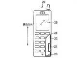
携帯装置10が携帯電話機である実施例について図2を参照して説明する。図示していないものもあるが、携帯電話機20は図1に示した各部に相当する機能ブロックを備えている。 An embodiment in which the
携帯装置10に相当する携帯電話機20には、バイブレータ1に相当するバイブレータ21が筐体22に固定されている。通常動作ではバイブレータ21の振動により携帯電話機20は図中の矢印の方向に振動する。一方、振動測定動作では、携帯電話機20を図中の振動方向に振動させることにより、バイブレータ21の振動子が上下動して電流を発生し、出力電流に応じて振動回数が検知され、振動回数に応じて不図示のアプリケーション処理部7が所定のアプリケーションプログラムを実行する。ここで、バイブレータ21は携帯電話機20の長手方向(表示装置25とキーボード24を結ぶ方向)に設置した例を示しているが、設置方向はいずれの方向でも構わない。 In a
本実施例ではバイブレータ1の構造例について図3を参照して説明する。 In the present embodiment, a structural example of the vibrator 1 will be described with reference to FIG.
バイブレータ30はバイブレータ1に相当し、円柱形状を有する直動式の電動モータである。
円筒状のコイルボビン33の外周にはコイル34が巻かれており、コイルボビン33は円柱状のインナーヨーク35に摺動可能に設置され、外装を兼ねる円筒状のアウターヨーク31の中立位置に保持されるようにバネ36a、36bで支えられている。 A
また、アウターヨーク31の内側にはマグネット32が設置され、インナーヨーク35の方向すなわちアウターヨーク31の中心軸方向に磁界を形成している。 A
ここで、アウターヨーク31、インナーヨーク35の材料は鉄などの磁性金属を用い、コイルボビンはプラスチックなどの非磁性材料を用いる。また、図示していないが、コイル34の両端はバイブレータ30の外部端子に接続されている。 Here, the
バイブレータ30の外部端子に直流電圧を供給すると、マグネット32により形成される磁界と、コイル34を流れる電流により、コイルボビン33はバネ36aを縮める方向、あるいはバネ36bを縮める方向に電磁力を受け移動する。ここで、例えば磁界がアウターヨーク31から中心軸に向かう方向、電流方向がコイル34の図面上側で見たとき、紙面に垂直で下から上であった場合、コイルボビン33はバネ36bを縮める方向の電磁力を受け移動する。また、負の直流電圧を供給すると、電流方向が逆転するため、上記と逆方向に電磁力を受ける。したがって、このバイブレータ30に交流電源を接続する通常動作においては、図中の可動方向にコイルボビン33が往復運動し、振動を発生する。 When a DC voltage is supplied to the external terminal of the
一方、バイブレータ30に電源を供給せず、図中の可動方向に振動を加えると、コイル34が巻かれたコイルボビン33が往復運動するため、マグネット32による磁界中をコイル34が移動するため、電磁誘導によりコイル34には電流が流れる。ここで、コイルボビン33の往復運動が1回生じると、移動方向により電流の向きが途中で反転する。すなわち、電流のプラス方向、あるいはマイナス方向の変化回数をカウントすることで、バイブレータ30に加わった振動回数が分かる。 On the other hand, if vibration is applied in the movable direction in the figure without supplying power to the
以上、本発明を実施の形態及び実施例に基づいて説明したが、本発明はこれに限定されるものではなく、当業者の通常の知識の範囲内でその変更や改良が可能であることは勿論である。 Although the present invention has been described based on the embodiments and examples, the present invention is not limited to this, and it is possible to make changes and improvements within the ordinary knowledge of those skilled in the art. Of course.
例えば、アプリケーション処理部7はCPU2と独立した処理装置として説明したが、これに限らず、CPU2がアプリケーション処理部7を兼ねることとしてもよい。 For example, although the application processing unit 7 has been described as a processing device independent of the
また、バイブレータ30において、振動量を大きくするため、コイルボビン33におもりを付加しても良い。 In the
また、本発明のバイブレータは本実施例のバイブレータ30の構成に限定されるものではなく、直動方式かつ交流電圧により駆動されるモータであれば構成は問わない。 Further, the vibrator according to the present invention is not limited to the structure of the
1、21、30 バイブレータ
2 CPU
3 切り替えスイッチ
4 交流電源装置
5 微分回路
6 カウント処理部
7 アプリケーション処理部
8 交流信号
10 携帯装置
20 携帯電話機
22 筐体
23 基板
24 キーボード
25 表示装置
31 アウターヨーク
32 マグネット
33 コイルボビン
34 コイル
35 インナーヨーク
36a、36b バネ1, 21, 30
DESCRIPTION OF SYMBOLS 3 Changeover switch 4 AC
Claims (10)
Translated fromJapanese交流電流の入力に応じて直線往復運動することにより前記振動を発生する振動子を有する直動方式のバイブレータであり、かつ、外力による前記振動子の上下動に応じて発電するバイブレータ、
前記バイブレータの出力を入力信号として、所定の処理を実行する処理部、
交流電源装置、及び、
前記バイブレータの接続先を、前記交流電源装置と前記処理部とのいずれか一方に切り替えるスイッチ
を備えることを特徴とする携帯装置。In a portable device provided with a vibrator that generates vibration for notifying the owner,
A vibrator of a direct acting system having a vibrator that generates the vibration by reciprocating linearly according to an input of an alternating current, and a vibrator that generates electric power in response to the vertical movement of the vibrator by an external force;
A processing unit that executes predetermined processing using the output of the vibrator as an input signal,
AC power supply, and
A portable device comprising a switch for switching a connection destination of the vibrator to one of the AC power supply device and the processing unit.
バイブレータの出力からパルス信号を生成する微分回路と、
前記微分回路が出力するパルスを計数して振動数を出力するカウント処理部と、
前記振動数を入力とするアプリケーションプログラムを実行するアプリケーション処理部と
を備えることを特徴とする携帯装置。The portable device according to claim 1, wherein the processing unit includes:
A differentiating circuit for generating a pulse signal from the output of the vibrator;
A count processing unit that counts pulses output by the differentiating circuit and outputs a vibration frequency;
A portable device comprising: an application processing unit that executes an application program that receives the frequency.
前記バイブレータは、交流電流の入力に応じて直線往復運動することにより前記振動を発生する振動子を有する直動方式のバイブレータであり、かつ、外力による前記振動子の上下動に応じて発電するバイブレータであって、
前記バイブレータの接続先を、交流電源装置から、所定の処理を実行する処理部へとスイッチにて切り替える段階と、
前記バイブレータが前記振動子の上下動に応じて発電して入力信号を生成する段階と、
前記スイッチを介して前記入力信号が前記処理部に入力される段階と、
前記入力信号に応じて前記処理部が所定の処理を実行する段階と
を含むことを特徴とする携帯装置での入力方法。In a method in which the owner inputs using a portable device including a vibrator that generates vibration for notifying the owner,
The vibrator is a linear motion type vibrator having a vibrator that generates the vibration by linearly reciprocating in response to an input of an alternating current, and that generates electric power according to the vertical movement of the vibrator by an external force. Because
The switch of the connection destination of the vibrator from the AC power supply device to a processing unit that executes a predetermined process with a switch,
The vibrator generates power according to the vertical movement of the vibrator to generate an input signal;
The input signal is input to the processing unit via the switch;
And a step of executing a predetermined process by the processing unit in response to the input signal.
バイブレータの出力からパルス信号を生成する段階と、
前記パルス信号を計数して振動数を出力する段階と、
前記振動数を入力とするアプリケーションプログラムを実行する段階と
を含むことを特徴とする携帯装置での入力方法。7. The input method using a portable device according to claim 6, wherein the predetermined process is:
Generating a pulse signal from the output of the vibrator;
Counting the pulse signal and outputting a vibration frequency;
And a step of executing an application program having the frequency as an input.
7. The input method for a portable device according to claim 6, wherein the portable device is a mobile communication terminal device.
Priority Applications (1)
| Application Number | Priority Date | Filing Date | Title |
|---|---|---|---|
| JP2005362638AJP2007166450A (en) | 2005-12-16 | 2005-12-16 | Portable device and input method of portable device |
Applications Claiming Priority (1)
| Application Number | Priority Date | Filing Date | Title |
|---|---|---|---|
| JP2005362638AJP2007166450A (en) | 2005-12-16 | 2005-12-16 | Portable device and input method of portable device |
Publications (1)
| Publication Number | Publication Date |
|---|---|
| JP2007166450Atrue JP2007166450A (en) | 2007-06-28 |
Family
ID=38248806
Family Applications (1)
| Application Number | Title | Priority Date | Filing Date |
|---|---|---|---|
| JP2005362638APendingJP2007166450A (en) | 2005-12-16 | 2005-12-16 | Portable device and input method of portable device |
Country Status (1)
| Country | Link |
|---|---|
| JP (1) | JP2007166450A (en) |
Cited By (4)
| Publication number | Priority date | Publication date | Assignee | Title |
|---|---|---|---|---|
| JP2010278726A (en)* | 2009-05-28 | 2010-12-09 | Kddi Corp | Mobile terminal with vibration communication function |
| JP2011172184A (en)* | 2010-02-22 | 2011-09-01 | Nec Corp | Mobile phone and display method of the same |
| JP2014500659A (en)* | 2010-11-05 | 2014-01-09 | クゥアルコム・インコーポレイテッド | Dynamic tapping force feedback for mobile devices |
| JP2015053732A (en)* | 2014-12-02 | 2015-03-19 | レノボ・イノベーションズ・リミテッド(香港) | Electronic device, control method, and program |
- 2005
- 2005-12-16JPJP2005362638Apatent/JP2007166450A/enactivePending
Cited By (5)
| Publication number | Priority date | Publication date | Assignee | Title |
|---|---|---|---|---|
| JP2010278726A (en)* | 2009-05-28 | 2010-12-09 | Kddi Corp | Mobile terminal with vibration communication function |
| JP2011172184A (en)* | 2010-02-22 | 2011-09-01 | Nec Corp | Mobile phone and display method of the same |
| JP2014500659A (en)* | 2010-11-05 | 2014-01-09 | クゥアルコム・インコーポレイテッド | Dynamic tapping force feedback for mobile devices |
| US9380145B2 (en) | 2010-11-05 | 2016-06-28 | Qualcomm Incorporated | Dynamic tapping force feedback for mobile devices |
| JP2015053732A (en)* | 2014-12-02 | 2015-03-19 | レノボ・イノベーションズ・リミテッド(香港) | Electronic device, control method, and program |
Similar Documents
| Publication | Publication Date | Title |
|---|---|---|
| US8797152B2 (en) | Haptic actuator apparatuses and methods thereof | |
| US10116194B2 (en) | Vibration motor | |
| KR101354773B1 (en) | Linear Motor | |
| US8536745B2 (en) | Linear vibrator | |
| US9619981B2 (en) | Haptic actuator | |
| US20170070132A1 (en) | Linear Vibrator | |
| JP2010509065A (en) | Ultra-small linear vibration device | |
| KR20130015342A (en) | Linear vibration device | |
| CN102055297A (en) | Linear vibrator | |
| KR20140113857A (en) | Vibrator and electronic apparatus having thereof | |
| CN105515331A (en) | Linear vibration motor | |
| JP2018030107A (en) | Haptic feedback system, electronic equipment and method for generating haptic feedback | |
| KR101624901B1 (en) | Impactive vibration generator and applied apparatus thereof | |
| US9774289B2 (en) | Method for driving vibrating motor | |
| KR20130015864A (en) | Linear vibration device | |
| JP2013103142A (en) | Vibration device | |
| JP2007166450A (en) | Portable device and input method of portable device | |
| CN106849593A (en) | It is drive linear vibration motor and electronic equipment more | |
| US11843297B2 (en) | Rotating vibration actuator with a weight and electronic apparatus | |
| KR20160114313A (en) | Haptic actuator | |
| KR101094651B1 (en) | Sensory signal output device | |
| CN102362152A (en) | Device for resonantly driving a micromechanical system | |
| US9667118B2 (en) | Vibration generating device having a faster reaction speed | |
| KR101078597B1 (en) | Horizontal Vibrating Linear Motor | |
| JP2012151985A (en) | Vibration power generator |
Legal Events
| Date | Code | Title | Description |
|---|---|---|---|
| A621 | Written request for application examination | Free format text:JAPANESE INTERMEDIATE CODE: A621 Effective date:20081112 | |
| A977 | Report on retrieval | Effective date:20090724 Free format text:JAPANESE INTERMEDIATE CODE: A971007 | |
| A131 | Notification of reasons for refusal | Effective date:20090902 Free format text:JAPANESE INTERMEDIATE CODE: A131 | |
| A02 | Decision of refusal | Free format text:JAPANESE INTERMEDIATE CODE: A02 Effective date:20100106 |