JP2007163763A - Connection jig for optical connectors - Google Patents
Connection jig for optical connectorsDownload PDFInfo
- Publication number
- JP2007163763A JP2007163763AJP2005359115AJP2005359115AJP2007163763AJP 2007163763 AJP2007163763 AJP 2007163763AJP 2005359115 AJP2005359115 AJP 2005359115AJP 2005359115 AJP2005359115 AJP 2005359115AJP 2007163763 AJP2007163763 AJP 2007163763A
- Authority
- JP
- Japan
- Prior art keywords
- optical
- connector
- optical fiber
- optical connector
- fiber
- Prior art date
- Legal status (The legal status is an assumption and is not a legal conclusion. Google has not performed a legal analysis and makes no representation as to the accuracy of the status listed.)
- Granted
Links
Images
Landscapes
- Mechanical Coupling Of Light Guides (AREA)
Abstract
Translated fromJapaneseDescription
Translated fromJapanese本発明は、現地組立型の光コネクタの接続作業に使用する接続治具に関するものである。 The present invention relates to a connecting jig used for connecting a field assembly type optical connector.
通信の分野においては、高速・大容量伝送が可能な光ファイバが伝送線路の主流となり、幹線から各家庭までの伝送経路を光ファイバ化するFTTH(Fiber To The Home)の普及が進んでいる。このFTTHの構築にあたり、光ファイバを基板上のV溝の内部で突き合わせて軸合わせを行うと共に、その状態で光ファイバ心線を固定することで、簡易に光ファイバ心線同士の接続を行う、メカニカルスプライスを用いた光ファイバの接続が行われている(特許文献1参照)。 In the field of communication, an optical fiber capable of high-speed and large-capacity transmission has become the mainstream of transmission lines, and FTTH (Fiber To The Home), which uses an optical fiber for the transmission path from the trunk line to each home, is in widespread use. In constructing this FTTH, the optical fibers are butted inside the V-groove on the substrate and aligned, and the optical fiber cores are fixed in this state, so that the optical fiber cores are easily connected to each other. Optical fibers are connected using a mechanical splice (see Patent Document 1).
しかし、メカニカルスプライスを用いて光ファイバを接続している場合、故障時の切り分けの際には、光ファイバを一度切断して装置とつないで調査を行った後に、再度メカニカルスプライスで接続し直すため、多くの手間がかかるという問題があった。 However, if the optical fiber is connected using a mechanical splice, in order to isolate it at the time of failure, the optical fiber is cut once and connected to the device, and then the mechanical splice is reconnected. There was a problem that it took a lot of work.
そこで、伝送経路の保守性や運用効率を向上させるため、光ファイバの接続における接続点の光コネクタ化が検討されている。そして、そのための方法として、光ファイバ(第一の光ファイバ)を予め光コネクタの内部のフェルールに内蔵固定している、メカニカルスプライスを応用した現地組立型の光コネクタが開発されている。 Therefore, in order to improve the maintainability and operational efficiency of the transmission path, the formation of an optical connector at the connection point in the connection of the optical fiber is being studied. As a method for this purpose, an on-site assembly type optical connector using a mechanical splice, in which an optical fiber (first optical fiber) is fixed in advance in a ferrule inside the optical connector, has been developed.
この現地組立型の光コネクタは、光ファイバが内蔵固定され先端研磨が施されてなるフェルールの後端部から突き出た光ファイバ(第一の光ファイバ)と別の光ファイバ(第二の光ファイバ)とを位置決め調心して、第一の光ファイバと第二の光ファイバとを突き合わせた状態で接続して、現地組立型の光コネクタと光ファイバ(第二の光ファイバ)とを固定することで光ファイバ同士の接続状態を維持する接続機構を有するフェルール付きメカニカルスプライスと、このフェルール付きメカニカルスプライスを収容するハウジングとを備えている。
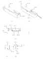
ところで、上記の現地組立型の光コネクタの組立方法は、例えば、図4に示すような、接続治具を用いて行う方法がある。接続治具401は、光コネクタ410内のメカニカルスプライス411に光ファイバを挿入するための隙間を発生するための楔402と、光ファイバを挿入するためのガイド403とを備え、一方、光コネクタ410内のメカニカルスプライス411には、前記接続治具401上の楔402を挿入するためのスリット412が形成されている(図4(a)、(c)、(d)参照)。そして、組立時には、このスリット412へ接続治具401上の楔402を挿入して、光ファイバを挿入するための隙間413を形成する(図4(e)参照)。 By the way, as for the method of assembling the above-mentioned field assembly type optical connector, for example, there is a method of using a connecting jig as shown in FIG. The connecting
つまり、端面処理を行った光ファイバ(第二の光ファイバ)405を、光コネクタの内部に挿入し、光ファイバ(第二の光ファイバ)をたわませることで、光コネクタの内部のフェルール406に内蔵固定された第一の光ファイバ(第一の光ファイバ)と光ファイバ(第二の光ファイバ)との突合せ確認を行った後、楔解除ボタン404を押すことで、スリット412から楔402を抜いて接続・組立するものであった。 In other words, the
このため、光ファイバの挿入作業と、くさび解除作業が異なる動作であるため、作業手順の間違いや、たわみ確認作業の忘れなど、柱上等の不安定な作業場ではミスの発生する可能性があり、安定した接続作業を容易に行うことが難しいという問題があった。 For this reason, since the optical fiber insertion work and the wedge release work are different operations, mistakes may occur in unstable work places such as on the pillar, such as mistakes in the work procedure or forgetting to check the deflection. There is a problem that it is difficult to perform stable connection work easily.
そこで、本発明は上記問題を解決するために案出されたものであり、安価な手段で、不安定な作業場においても、容易に且つ安定した接続作業を実現できる現地組立型の光コネクタ用接続治具を提供することにある。 Therefore, the present invention has been devised to solve the above-mentioned problems, and is a locally assembled optical connector connection that can realize an easy and stable connection operation even in an unstable work place by an inexpensive means. To provide a jig.
上記目的を達成するために、請求項1の発明は、光コネクタの内部のフェルールに内蔵固定された第一の光ファイバと、前記光コネクタの外部から前記光コネクタの内部に挿入する第二の光ファイバとを位置決め調心して、前記第一の光ファイバと前記第二の光ファイバとを突き合わせた状態で接続して、前記光コネクタと前記第二の光ファイバとを固定する際に使用する光コネクタ用接続治具であって、前記光コネクタを位置決めするコネクタホルダと、前記第二の光ファイバを前記光コネクタに挿入するためのガイド溝を備えたガイド部材とを備え、前記コネクタホルダと前記ガイド部材とを前記第二の光ファイバの光軸方向に近接させることにより、前記光コネクタと前記第二の光ファイバとの固定を行なうことができるものである。 To achieve the above object, the invention of
また、請求項2の発明は、光コネクタの内部のフェルールに内蔵固定された第一の光ファイバと、前記光コネクタの外部から前記光コネクタの内部に挿入する第二の光ファイバとを位置決め調心して、前記第一の光ファイバと前記第二の光ファイバとを突き合わせた状態で接続して、前記光コネクタと前記第二の光ファイバとを固定する際に使用する光コネクタ用接続治具であって、前記光コネクタを位置決めするコネクタホルダと、前記第二の光ファイバを前記光コネクタに挿入するためのガイド溝を備えたガイド部材とを備え、前記コネクタホルダと前記ガイド部材とを前記第二の光ファイバの光軸方向に近接させることにより、前記ガイド部材が前記光コネクタを移動させることで、前記光コネクタと前記第二の光ファイバとの固定を行なうことができるものである。なお、ガイド部材が光コネクタを移動させる方向としては、例えば、コネクタホルダの上下方向などが考えられる。 According to a second aspect of the present invention, the first optical fiber built in and fixed to the ferrule inside the optical connector and the second optical fiber inserted into the optical connector from the outside of the optical connector are positioned and adjusted. In mind, the first optical fiber and the second optical fiber are connected in a butted state, and the optical connector connecting jig used when fixing the optical connector and the second optical fiber. A connector holder for positioning the optical connector; and a guide member provided with a guide groove for inserting the second optical fiber into the optical connector. The connector holder and the guide member are The guide member moves the optical connector by moving the optical connector closer to the optical axis direction of the second optical fiber, thereby fixing the optical connector and the second optical fiber. It is those that can Nau. In addition, as a direction where a guide member moves an optical connector, the up-down direction of a connector holder etc. can be considered, for example.
また、請求項3に記載の発明は、光コネクタの内部のフェルールに内蔵固定された第一の光ファイバと、前記光コネクタの外部から前記光コネクタの内部に挿入する第二の光ファイバとを前記光コネクタの内部のメカニカルスプライスで位置決め調心して、前記第一の光ファイバと前記第二の光ファイバとを突き合わせた状態で接続して、前記光コネクタと前記第二の光ファイバとを固定する際に使用する光コネクタ用接続治具であって、前記光コネクタに前記第二の光ファイバを挿入するために、前記メカニカルスプライスを開くための楔を備えた、前記光コネクタを位置決めするコネクタホルダと、前記第二の光ファイバを前記光コネクタに挿入するためのガイド溝を備えたガイド部材とを備え、前記コネクタホルダと前記ガイド部材とを前記第二の光ファイバの光軸方向に近接させることにより、前記ガイド部材が前記光コネクタを押し上げることで前記光コネクタから前記楔を抜き、これにより前記光コネクタと前記第二の光ファイバとの固定を行なうことができるものである。 According to a third aspect of the present invention, a first optical fiber built in and fixed to a ferrule inside the optical connector and a second optical fiber inserted into the optical connector from the outside of the optical connector are provided. Positioning and alignment with a mechanical splice inside the optical connector, the first optical fiber and the second optical fiber are connected in a butted state, and the optical connector and the second optical fiber are fixed. A connector holder for positioning the optical connector, comprising a wedge for opening the mechanical splice for inserting the second optical fiber into the optical connector. And a guide member provided with a guide groove for inserting the second optical fiber into the optical connector, the connector holder and the guide member, The guide member pushes up the optical connector to pull out the wedge from the optical connector by bringing the second optical fiber close to the optical axis direction, and thereby the optical connector and the second optical fiber It can be fixed.
また、請求項4に記載の発明は、光コネクタの内部のフェルールに内蔵固定された第一の光ファイバと、前記光コネクタの外部から前記光コネクタの内部に挿入する第二の光ファイバとを前記光コネクタの内部のメカニカルスプライスで位置決め調心して、前記第一の光ファイバと前記第二の光ファイバとを突き合わせた状態で接続して、前記光コネクタと前記第二の光ファイバとを固定する際に使用する光コネクタ用接続治具であって、前記光コネクタに前記第二の光ファイバを挿入するために、前記メカニカルスプライスを開くための楔を備えた、前記光コネクタを位置決めするコネクタホルダと、前記第二の光ファイバを前記光コネクタに挿入するためのガイド溝を備えたガイド部材とを備え、前記コネクタホルダと前記ガイド部材を前記第二の光ファイバの光軸方向に近接させることにより、前記コネクタホルダが前記光コネクタから離間することで、前記コネクタホルダに備えられた前記楔が前記光コネクタから離間され、これにより前記光コネクタと前記第二の光ファイバとの固定を行なうことができるものである。 According to a fourth aspect of the present invention, there is provided a first optical fiber that is built in and fixed to a ferrule inside the optical connector, and a second optical fiber that is inserted into the optical connector from the outside of the optical connector. Positioning and alignment with a mechanical splice inside the optical connector, the first optical fiber and the second optical fiber are connected in a butted state, and the optical connector and the second optical fiber are fixed. A connector holder for positioning the optical connector, comprising a wedge for opening the mechanical splice for inserting the second optical fiber into the optical connector. And a guide member having a guide groove for inserting the second optical fiber into the optical connector, the connector holder and the guide member By bringing the second optical fiber close to the optical axis direction, the connector holder is separated from the optical connector, so that the wedge provided in the connector holder is separated from the optical connector, whereby the light The connector and the second optical fiber can be fixed.
本発明によれば、安価な手段で、不安定な作業場においても、容易に且つ安定した接続作業を安価に実現できる光コネクタ用接続治具を提供することにある。 According to the present invention, there is provided an optical connector connection jig that can realize an easy and stable connection work at low cost even in an unstable work place by an inexpensive means.
以下、本発明を実施するための最良の形態を図面に基づいて詳述する。 Hereinafter, the best mode for carrying out the present invention will be described in detail with reference to the drawings.
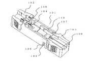
本発明の実施の形態に係る接続治具を図1に示す。 A connection jig according to an embodiment of the present invention is shown in FIG.
図1に示すように、本発明の実施の形態に係る光コネクタ用接続治具は、容易に且つ安定した、光ファイバの光コネクタへの接続作業を安価に実現するためのものであって、光コネクタを位置決めするコネクタホルダ102と、光ファイバを挿入するためのガイド部材103とからなる。 As shown in FIG. 1, the optical connector connection jig according to the embodiment of the present invention is for realizing an easy and stable connection work of an optical fiber to an optical connector at low cost, It comprises a
本実施形態の光コネクタ用接続治具101は、コネクタホルダ102上に、光コネクタ内に光ファイバを挿入するための隙間を開けるための楔104と、ガイド部材103をコネクタホルダ102に係止するための凹部105が形成されている。ガイド部材103には、光ファイバを把持したファイバホルダ(心線把持具)をガイドするためのガイド溝106と、ファイバホルダを簡易固定するための変位可能な突起107と、ファイバホルダのためのストップ溝110と、光コネクタを押し上げるための押し上げ部材108と、コネクタホルダ102をガイド部材103に係止するための凸部109が形成されている。 The optical connector connecting jig 101 of the present embodiment locks a
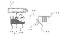
図2に示すように、本発明の実施の形態に係る接続治具は、コネクタホルダ102とガイド部材103とが、凹部105と凸部109とを嵌合させることにより組み立てられ、凸部109を凹部105内で移動させることで、互いに近接、離間させることが出来る。コネクタホルダ102とガイド部材103とを近接させたとき、コネクタホルダ102の傾斜部111と、ガイド部材103の押し上げ部材108とが互いにスライドするようになっている。そして、これにより、コネクタホルダ102とガイド部材103とを近接させることで光コネクタ112を押し上げることが出来る。 As shown in FIG. 2, the connection jig according to the embodiment of the present invention is assembled by fitting the
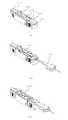
本実施形態の接続治具を用いた光コネクタの組立方法を図3によって説明する。 An optical connector assembling method using the connection jig of this embodiment will be described with reference to FIG.
本実施形態の接続治具は、図3に示すように、(1)コネクタホルダ102へ光コネクタ102をセットする。このとき、図2を用いた説明部分で前述したように、光コネクタ102内に楔104(図1、図2参照)が挿入される(図3(a)参照)。 As shown in FIG. 3, the connection jig of the present embodiment sets (1) the
(2)光ファイバの端末処理を行ったファイバホルダ(心線把持具)301を、ガイド部材103のガイド溝106に沿ってスライドさせて光ファイバ(第二の光ファイバ)302を光コネクタ112内へ挿入していく(図3(b)参照)。 (2) A fiber holder (core wire gripper) 301 that has been subjected to optical fiber end processing is slid along the guide groove 106 of the guide member 103 to place the optical fiber (second optical fiber) 302 in the optical connector 112. (See FIG. 3B).
(3)そのまま、ファイバホルダ(心線把持具)301を光ファイバ(第二の光ファイバ)302の光軸方向(光ファイバ(第二の光ファイバ)302を光コネクタ112内へ挿入していく方向と同じ方向)に押していくと、ファイバホルダ(心線把持具)301がストップ溝110の位置でガイド部材103に引っ掛かる。そして、さらにファイバホルダ(心線把持具)301を光ファイバ302の光軸方向に押していくことにより、ファイバホルダ(心線把持具)301におけるストップ溝110に引っ掛かった部分を介してガイド部材103に光軸方向へ向けた力を加えることができる。そして、さらにファイバホルダ(心線把持具)301を押していくことにより、ファイバホルダ(心線把持具)301と共にガイド部材103も押すことができ、これにより、ガイド部材103とコネクタホルダ102が近接することになる。そして、その結果、コネクタホルダ102の傾斜部111と、ガイド部材103の押し上げ部材108とが互いにスライドし、光コネクタ112が押し上げられるので、これにより楔104から光コネクタ112が外れることとなる。 (3) The fiber holder (core wire gripper) 301 is inserted into the optical connector 112 as it is in the optical axis direction (optical fiber (second optical fiber) 302) of the optical fiber (second optical fiber) 302. When pushed in the same direction as the direction, the fiber holder (core wire gripping tool) 301 is hooked on the guide member 103 at the position of the stop groove 110. Further, by pushing the fiber holder (core wire gripping tool) 301 in the direction of the optical axis of the optical fiber 302, the guide member 103 is inserted into the fiber holder (core wire gripping tool) 301 through the portion caught by the stop groove 110. A force directed in the optical axis direction can be applied. Further, by pushing the fiber holder (core wire gripping tool) 301, the guide member 103 can be pushed together with the fiber holder (core wire gripping tool) 301, so that the guide member 103 and the
しかし、楔104から光コネクタ112が外れる前に光ファイバ302にたわみ303が発生し、光コネクタ112の内部のフェルール(図4参照)に内蔵固定された光ファイバ(第一の光ファイバ)(図示せず)と光ファイバ(第二の光ファイバ)302とが位置決め調心され、第一の光ファイバと第二の光ファイバ302とが突き合わされた状態で接続され、光コネクタ112と光ファイバ(第二の光ファイバ)302とが固定される。つまり、光ファイバ302の突き合わせ作業を確実に実施することができる(図3(c)参照)。そして、これにより、光コネクタ112と光ファイバ(第二の光ファイバ)302とが固定されて組立が完了する。 However, before the optical connector 112 is detached from the
これにより、光コネクタの接続作業が、一連の動作で実施することができるため、作業手順の間違いや、たわみ確認作業の忘れなどが発生せず、柱上等の不安定な作業場でもミスの発生を防ぐことができ、安定した接続作業を容易に行うことを実現できる。 As a result, the connection work of the optical connector can be carried out in a series of operations, so there is no mistake in the work procedure or forgetting the deflection confirmation work, and errors occur even in unstable work places such as on pillars. Can be prevented, and stable connection work can be easily performed.
本発明の実施の形態においては、コネクタホルダに光コネクタを固定する形態としているが、ガイド部材に光コネクタを固定して、コネクタホルダを移動させることで楔を抜く形態であってもかまわない。 In the embodiment of the present invention, the optical connector is fixed to the connector holder. However, the optical connector may be fixed to the guide member, and the wedge may be pulled out by moving the connector holder.
本発明の他の実施の形態としては、コネクタホルダとガイド部材とを第二の光ファイバの光軸方向に近接させたときに、ガイド部材が光コネクタを、コネクタホルダの下方向に移動させることで、光コネクタと第二の光ファイバとの接続を行なう形態が考えられる。 As another embodiment of the present invention, when the connector holder and the guide member are brought close to the optical axis direction of the second optical fiber, the guide member moves the optical connector downward. Thus, a form in which the optical connector and the second optical fiber are connected can be considered.
101 光コネクタ用接続治具
102 コネクタホルダ
103 ガイド部材
104 楔
105 凹部
106 ガイド溝
107 突起
108 押し上げ部材
109 凸部
110 ストップ溝
111 傾斜部
112 光コネクタ
301 ファイバホルダ(心線把持具)
302 光ファイバ(第二の光ファイバ)
303 たわみ
401 接続治具
402 楔
403 ガイド
404 楔解除ボタン
405 光ファイバ(第二の光ファイバ)
406 フェルール
410 光コネクタ
411 メカニカルスプライス
412 スリット
413 隙間DESCRIPTION OF SYMBOLS 101 Connection jig for
302 optical fiber (second optical fiber)
303
406
Claims (4)
Translated fromJapanese前記光コネクタを位置決めするコネクタホルダと、前記第二の光ファイバを前記光コネクタに挿入するためのガイド溝を備えたガイド部材とを備え、
前記コネクタホルダに前記光コネクタをセットし、前記第二の光ファイバを前記光コネクタ内へ挿入した後に、前記コネクタホルダと前記ガイド部材とを前記第二の光ファイバの光軸方向に近接させることにより、前記光コネクタと前記第二の光ファイバとの固定を行なうことを特徴とする光コネクタ用接続治具。Positioning and aligning the first optical fiber built in and fixed to the ferrule inside the optical connector and the second optical fiber inserted into the optical connector from the outside of the optical connector, the first optical fiber and A connection jig for an optical connector that is used when the optical connector and the second optical fiber are fixed by connecting the second optical fiber in a butted state,
A connector holder for positioning the optical connector; and a guide member having a guide groove for inserting the second optical fiber into the optical connector;
After the optical connector is set in the connector holder and the second optical fiber is inserted into the optical connector, the connector holder and the guide member are brought close to each other in the optical axis direction of the second optical fiber. Thus, the optical connector and the second optical fiber are fixed to each other.
前記光コネクタを位置決めするコネクタホルダと、前記第二の光ファイバを前記光コネクタに挿入するためのガイド溝を備えたガイド部材とを備え、
前記コネクタホルダに前記光コネクタをセットし、前記第二の光ファイバを前記光コネクタ内へ挿入した後に、前記コネクタホルダと前記ガイド部材とを前記第二の光ファイバの光軸方向に近接させることにより、前記ガイド部材が前記光コネクタを移動させることで、前記光コネクタと前記第二の光ファイバとの固定を行なうことを特徴とする光コネクタ用接続治具。Positioning and aligning the first optical fiber built in and fixed to the ferrule inside the optical connector and the second optical fiber inserted into the optical connector from the outside of the optical connector, the first optical fiber and A connection jig for an optical connector that is used when the optical connector and the second optical fiber are fixed by connecting the second optical fiber in a butted state,
A connector holder for positioning the optical connector; and a guide member having a guide groove for inserting the second optical fiber into the optical connector;
After the optical connector is set in the connector holder and the second optical fiber is inserted into the optical connector, the connector holder and the guide member are brought close to each other in the optical axis direction of the second optical fiber. Accordingly, the optical connector and the second optical fiber are fixed by moving the optical connector by the guide member.
前記光コネクタに前記第二の光ファイバを挿入するために、前記メカニカルスプライスを開くための楔を備えた、前記光コネクタを位置決めするコネクタホルダと、前記第二の光ファイバを前記光コネクタに挿入するためのガイド溝を備えたガイド部材とを備え、
前記光コネクタ内に前記楔を挿入することにより、前記コネクタホルダに前記光コネクタをセットし、前記第二の光ファイバを前記光コネクタ内へ挿入した後に、前記コネクタホルダと前記ガイド部材とを前記第二の光ファイバの光軸方向に近接させることにより、前記ガイド部材が前記光コネクタを押し上げることで前記光コネクタから前記楔を抜き、これにより前記光コネクタと前記第二の光ファイバとの固定を行なうことを特徴とする光コネクタ用接続治具。The first optical fiber built in and fixed to the ferrule inside the optical connector and the second optical fiber inserted into the optical connector from the outside of the optical connector are positioned and adjusted by a mechanical splice inside the optical connector. In mind, the first optical fiber and the second optical fiber are connected in a butted state, and the optical connector connecting jig used when fixing the optical connector and the second optical fiber. There,
In order to insert the second optical fiber into the optical connector, a connector holder for positioning the optical connector provided with a wedge for opening the mechanical splice, and inserting the second optical fiber into the optical connector A guide member provided with a guide groove for
By inserting the wedge into the optical connector, the optical connector is set in the connector holder, and after inserting the second optical fiber into the optical connector, the connector holder and the guide member are By bringing the second optical fiber close to the optical axis direction, the guide member pushes up the optical connector to pull out the wedge from the optical connector, thereby fixing the optical connector and the second optical fiber. A connecting jig for optical connectors, characterized by:
前記光コネクタに前記第二の光ファイバを挿入するために、前記メカニカルスプライスを開くための楔を備えた、前記光コネクタを位置決めするコネクタホルダと、前記第二の光ファイバを前記光コネクタに挿入するためのガイド溝を備えたガイド部材とを備え、
前記光コネクタ内に前記楔を挿入することにより、前記コネクタホルダに前記光コネクタをセットし、前記第二の光ファイバを前記光コネクタ内へ挿入した後に、前記コネクタホルダと前記ガイド部材を前記第二の光ファイバの光軸方向に近接させることにより、前記コネクタホルダが前記光コネクタから離間することで、前記コネクタホルダに備えられた前記楔が前記光コネクタから離間され、これにより前記光コネクタと前記第二の光ファイバとの固定を行なうことを特徴とする光コネクタ用接続治具。The first optical fiber built in and fixed to the ferrule inside the optical connector and the second optical fiber inserted into the optical connector from the outside of the optical connector are positioned and adjusted by a mechanical splice inside the optical connector. In mind, the first optical fiber and the second optical fiber are connected in a butted state, and the optical connector connecting jig used when fixing the optical connector and the second optical fiber. There,
In order to insert the second optical fiber into the optical connector, a connector holder for positioning the optical connector provided with a wedge for opening the mechanical splice, and inserting the second optical fiber into the optical connector A guide member provided with a guide groove for
By inserting the wedge into the optical connector, the optical connector is set in the connector holder, and after inserting the second optical fiber into the optical connector, the connector holder and the guide member are By bringing the second optical fiber close to the optical axis direction, the connector holder is separated from the optical connector, so that the wedge provided in the connector holder is separated from the optical connector. A connection jig for an optical connector, wherein the connection jig is fixed to the second optical fiber.
Priority Applications (1)
| Application Number | Priority Date | Filing Date | Title |
|---|---|---|---|
| JP2005359115AJP4441480B2 (en) | 2005-12-13 | 2005-12-13 | Connection jig for optical connectors |
Applications Claiming Priority (1)
| Application Number | Priority Date | Filing Date | Title |
|---|---|---|---|
| JP2005359115AJP4441480B2 (en) | 2005-12-13 | 2005-12-13 | Connection jig for optical connectors |
Publications (2)
| Publication Number | Publication Date |
|---|---|
| JP2007163763Atrue JP2007163763A (en) | 2007-06-28 |
| JP4441480B2 JP4441480B2 (en) | 2010-03-31 |
Family
ID=38246728
Family Applications (1)
| Application Number | Title | Priority Date | Filing Date |
|---|---|---|---|
| JP2005359115AActiveJP4441480B2 (en) | 2005-12-13 | 2005-12-13 | Connection jig for optical connectors |
Country Status (1)
| Country | Link |
|---|---|
| JP (1) | JP4441480B2 (en) |
Cited By (4)
| Publication number | Priority date | Publication date | Assignee | Title |
|---|---|---|---|---|
| EP2006908A2 (en) | 2007-06-21 | 2008-12-24 | Shinko Electric Industries Co., Ltd. | Electronic device and method of manufacturing the same |
| WO2009136583A1 (en)* | 2008-05-09 | 2009-11-12 | 住友電気工業株式会社 | Optical connector assembling jig and optical connector assembling method |
| JP2012515936A (en)* | 2009-01-19 | 2012-07-12 | コーニング ケーブル システムズ リミテッド ライアビリティ カンパニー | Termination system for optical fiber connection |
| JP7620148B1 (en)* | 2024-05-30 | 2025-01-22 | 株式会社フジクラ | Optical fiber processing tools |
Citations (14)
| Publication number | Priority date | Publication date | Assignee | Title |
|---|---|---|---|---|
| JP2004077929A (en)* | 2002-08-20 | 2004-03-11 | Fujikura Ltd | Optical connector assembly tool and optical fiber connection method |
| WO2004072703A1 (en)* | 2003-02-17 | 2004-08-26 | Sumitomo Electric Industries, Ltd. | Optical fiber connecting tool |
| JP2005062514A (en)* | 2003-08-13 | 2005-03-10 | Fujikura Ltd | Wedge insertion / removal parts for optical connectors, optical connectors with wedge parts |
| JP2005077837A (en)* | 2003-09-01 | 2005-03-24 | Hirose Electric Co Ltd | Optical connector having shielding mechanism |
| JP2005099706A (en)* | 2003-06-03 | 2005-04-14 | Fujikura Ltd | Optical fiber connection tool, connector holder, optical connector with connector holder, optical connector with tool |
| JP2005157286A (en)* | 2003-10-29 | 2005-06-16 | Sumitomo Electric Ind Ltd | Optical fiber connecting jig and optical connector assembling method |
| JP2005202199A (en)* | 2004-01-16 | 2005-07-28 | Fujikura Ltd | Optical fiber connection tool |
| JP2005215545A (en)* | 2004-01-30 | 2005-08-11 | Sumitomo Electric Ind Ltd | Optical fiber connecting jig and optical connector manufacturing method |
| JP2005283954A (en)* | 2004-03-30 | 2005-10-13 | Fujikura Ltd | Optical connector, optical connector assembly method |
| JP2005292429A (en)* | 2004-03-31 | 2005-10-20 | Fujikura Ltd | Optical fiber connection opening member, optical fiber connection tool, optical connector, optical fiber connector and optical fiber butt connection confirmation method |
| JP2005300894A (en)* | 2004-04-12 | 2005-10-27 | Fujikura Ltd | Optical fiber connector and optical fiber with optical fiber connector |
| JP2007121863A (en)* | 2005-10-31 | 2007-05-17 | Fujikura Ltd | Optical connector installation tool |
| JP2007121886A (en)* | 2005-10-31 | 2007-05-17 | Sumitomo Electric Ind Ltd | Optical fiber connection jig |
| JP2007156331A (en)* | 2005-12-08 | 2007-06-21 | Fujikura Ltd | Optical connector tool |
- 2005
- 2005-12-13JPJP2005359115Apatent/JP4441480B2/enactiveActive
Patent Citations (14)
| Publication number | Priority date | Publication date | Assignee | Title |
|---|---|---|---|---|
| JP2004077929A (en)* | 2002-08-20 | 2004-03-11 | Fujikura Ltd | Optical connector assembly tool and optical fiber connection method |
| WO2004072703A1 (en)* | 2003-02-17 | 2004-08-26 | Sumitomo Electric Industries, Ltd. | Optical fiber connecting tool |
| JP2005099706A (en)* | 2003-06-03 | 2005-04-14 | Fujikura Ltd | Optical fiber connection tool, connector holder, optical connector with connector holder, optical connector with tool |
| JP2005062514A (en)* | 2003-08-13 | 2005-03-10 | Fujikura Ltd | Wedge insertion / removal parts for optical connectors, optical connectors with wedge parts |
| JP2005077837A (en)* | 2003-09-01 | 2005-03-24 | Hirose Electric Co Ltd | Optical connector having shielding mechanism |
| JP2005157286A (en)* | 2003-10-29 | 2005-06-16 | Sumitomo Electric Ind Ltd | Optical fiber connecting jig and optical connector assembling method |
| JP2005202199A (en)* | 2004-01-16 | 2005-07-28 | Fujikura Ltd | Optical fiber connection tool |
| JP2005215545A (en)* | 2004-01-30 | 2005-08-11 | Sumitomo Electric Ind Ltd | Optical fiber connecting jig and optical connector manufacturing method |
| JP2005283954A (en)* | 2004-03-30 | 2005-10-13 | Fujikura Ltd | Optical connector, optical connector assembly method |
| JP2005292429A (en)* | 2004-03-31 | 2005-10-20 | Fujikura Ltd | Optical fiber connection opening member, optical fiber connection tool, optical connector, optical fiber connector and optical fiber butt connection confirmation method |
| JP2005300894A (en)* | 2004-04-12 | 2005-10-27 | Fujikura Ltd | Optical fiber connector and optical fiber with optical fiber connector |
| JP2007121863A (en)* | 2005-10-31 | 2007-05-17 | Fujikura Ltd | Optical connector installation tool |
| JP2007121886A (en)* | 2005-10-31 | 2007-05-17 | Sumitomo Electric Ind Ltd | Optical fiber connection jig |
| JP2007156331A (en)* | 2005-12-08 | 2007-06-21 | Fujikura Ltd | Optical connector tool |
Cited By (6)
| Publication number | Priority date | Publication date | Assignee | Title |
|---|---|---|---|---|
| EP2006908A2 (en) | 2007-06-21 | 2008-12-24 | Shinko Electric Industries Co., Ltd. | Electronic device and method of manufacturing the same |
| WO2009136583A1 (en)* | 2008-05-09 | 2009-11-12 | 住友電気工業株式会社 | Optical connector assembling jig and optical connector assembling method |
| JP2009271431A (en)* | 2008-05-09 | 2009-11-19 | Sumitomo Electric Ind Ltd | Optical connector assembling tool and optical connector assembling method |
| US8401356B2 (en) | 2008-05-09 | 2013-03-19 | Sumitomo Electric Industries, Ltd. | Optical connector assembling jig and optical connector assembling method |
| JP2012515936A (en)* | 2009-01-19 | 2012-07-12 | コーニング ケーブル システムズ リミテッド ライアビリティ カンパニー | Termination system for optical fiber connection |
| JP7620148B1 (en)* | 2024-05-30 | 2025-01-22 | 株式会社フジクラ | Optical fiber processing tools |
Also Published As
| Publication number | Publication date |
|---|---|
| JP4441480B2 (en) | 2010-03-31 |
Similar Documents
| Publication | Publication Date | Title |
|---|---|---|
| JP4699546B2 (en) | Optical fiber connection method and optical fiber connection tool | |
| JP2006030669A (en) | Optical connector and optical fiber connection system | |
| JP2007121859A (en) | Optical connector receptacle and optical connector | |
| JP2012037624A (en) | Optical connector and optical connector assembly tool | |
| JP4441480B2 (en) | Connection jig for optical connectors | |
| JP4191168B2 (en) | Mechanical connection type optical connector | |
| JP4387732B2 (en) | Optical connector | |
| US20240402438A1 (en) | Ferrule holding structure | |
| JP2008262245A (en) | Optical connector assembly tool | |
| JP2005107309A (en) | Optical connector and optical connector assembling method | |
| JP2013015745A (en) | Optical connector | |
| JP4372803B2 (en) | Optical fiber connection method | |
| CN117980792A (en) | Holding structure of insertion core | |
| JP2007121878A (en) | Optical connector connection tool | |
| JP4226585B2 (en) | Optical connector installation tool | |
| EP2466352B1 (en) | Method for connecting optical fibers | |
| JP2011150072A (en) | Optical connector and connecting method of optical cable using the same | |
| JP4422669B2 (en) | Optical fiber terminal processing tool and field assembly type optical connector assembly method | |
| JP2013003222A (en) | Optical connector | |
| JP4303713B2 (en) | Optical fiber core holding member and optical connector connection method | |
| JP4163077B2 (en) | Optical connector | |
| JP2013015786A (en) | Optical connector | |
| JP2020012914A (en) | Optical fiber connection tool | |
| JP2011002670A (en) | Method of splicing beveled end face optical fibers | |
| JP4581666B2 (en) | Optical fiber connection parts |
Legal Events
| Date | Code | Title | Description |
|---|---|---|---|
| A977 | Report on retrieval | Free format text:JAPANESE INTERMEDIATE CODE: A971007 Effective date:20080812 | |
| A131 | Notification of reasons for refusal | Free format text:JAPANESE INTERMEDIATE CODE: A131 Effective date:20080826 | |
| A521 | Written amendment | Free format text:JAPANESE INTERMEDIATE CODE: A523 Effective date:20081024 | |
| A131 | Notification of reasons for refusal | Free format text:JAPANESE INTERMEDIATE CODE: A131 Effective date:20090331 | |
| A521 | Written amendment | Free format text:JAPANESE INTERMEDIATE CODE: A523 Effective date:20090529 | |
| TRDD | Decision of grant or rejection written | ||
| A01 | Written decision to grant a patent or to grant a registration (utility model) | Free format text:JAPANESE INTERMEDIATE CODE: A01 Effective date:20100105 | |
| A01 | Written decision to grant a patent or to grant a registration (utility model) | Free format text:JAPANESE INTERMEDIATE CODE: A01 | |
| A61 | First payment of annual fees (during grant procedure) | Free format text:JAPANESE INTERMEDIATE CODE: A61 Effective date:20100108 | |
| FPAY | Renewal fee payment (event date is renewal date of database) | Free format text:PAYMENT UNTIL: 20130115 Year of fee payment:3 | |
| R150 | Certificate of patent or registration of utility model | Ref document number:4441480 Country of ref document:JP Free format text:JAPANESE INTERMEDIATE CODE: R150 Free format text:JAPANESE INTERMEDIATE CODE: R150 | |
| FPAY | Renewal fee payment (event date is renewal date of database) | Free format text:PAYMENT UNTIL: 20140115 Year of fee payment:4 | |
| S111 | Request for change of ownership or part of ownership | Free format text:JAPANESE INTERMEDIATE CODE: R313115 | |
| R350 | Written notification of registration of transfer | Free format text:JAPANESE INTERMEDIATE CODE: R350 | |
| S531 | Written request for registration of change of domicile | Free format text:JAPANESE INTERMEDIATE CODE: R313531 | |
| R350 | Written notification of registration of transfer | Free format text:JAPANESE INTERMEDIATE CODE: R350 | |
| S111 | Request for change of ownership or part of ownership | Free format text:JAPANESE INTERMEDIATE CODE: R313117 | |
| R350 | Written notification of registration of transfer | Free format text:JAPANESE INTERMEDIATE CODE: R350 |