JP2007152526A - Grinder - Google Patents
GrinderDownload PDFInfo
- Publication number
- JP2007152526A JP2007152526AJP2005353950AJP2005353950AJP2007152526AJP 2007152526 AJP2007152526 AJP 2007152526AJP 2005353950 AJP2005353950 AJP 2005353950AJP 2005353950 AJP2005353950 AJP 2005353950AJP 2007152526 AJP2007152526 AJP 2007152526A
- Authority
- JP
- Japan
- Prior art keywords
- housing
- lock member
- cooling air
- spindle
- gear
- Prior art date
- Legal status (The legal status is an assumption and is not a legal conclusion. Google has not performed a legal analysis and makes no representation as to the accuracy of the status listed.)
- Pending
Links
- 238000001816coolingMethods0.000claimsabstractdescription26
- 238000009434installationMethods0.000claimsdescription7
- 238000007664blowingMethods0.000claimsdescription4
- 239000000428dustSubstances0.000abstractdescription13
- 239000000843powderSubstances0.000abstract2
- 230000002349favourable effectEffects0.000abstract1
- 230000008878couplingEffects0.000description2
- 238000010168coupling processMethods0.000description2
- 238000005859coupling reactionMethods0.000description2
- 239000000463materialSubstances0.000description2
- 238000005498polishingMethods0.000description2
- 230000003111delayed effectEffects0.000description1
- 230000000694effectsEffects0.000description1
- 230000006698inductionEffects0.000description1
- 230000009545invasionEffects0.000description1
- 230000035515penetrationEffects0.000description1
- 238000009423ventilationMethods0.000description1
Images

Landscapes
- Finish Polishing, Edge Sharpening, And Grinding By Specific Grinding Devices (AREA)
Abstract
Description
Translated fromJapanese本発明は、ハウジングの下方へ突出させたスピンドルに円盤状砥石を装着し、円盤状砥石の回転によって研磨作業が可能となるグラインダに関する。 The present invention relates to a grinder in which a disc-shaped grindstone is mounted on a spindle that protrudes downward from a housing, and a grinding operation can be performed by rotating the disc-shaped grindstone.
グラインダは、ハウジング内に、スピンドルを上下方向に軸支してハウジングの下方に突出させ、その突出端に円盤状砥石を直交状に装着して、スピンドルと共に回転させた円盤状砥石によって被研磨材の研磨作業を可能としている。また、スピンドルには、ハウジング内へ突出するモータの出力軸から回転伝達されるベベルギヤ等のギヤが、キー結合や二面幅による嵌合等の結合手段によって一体回転可能に外装されている。
一方、グラインダには、スピンドルに対する円盤状砥石の着脱を容易とするために、ハウジングに、スピンドルの回転を任意にロック可能なロック部材が設けられている。このロック部材は、例えば特許文献1に示すように、ハウジングの上方でハウジング内へ出没可能且つ突出位置への付勢状態で設けられる軸体で、ハウジング内への押し込み操作により、ベベルギヤの上面に設けられた凹部に下端が嵌合し、ベベルギヤを介してスピンドルの回転をロックするものである。A grinder is a material to be polished by a disc-shaped grindstone that is supported by a spindle mounted in a vertical direction in a housing and protrudes downward from the housing. The polishing work is possible. Further, a gear such as a bevel gear, which is rotationally transmitted from the output shaft of the motor that protrudes into the housing, is externally mounted on the spindle so as to be integrally rotatable by a coupling means such as a key coupling or a two-surface width fitting.
On the other hand, the grinder is provided with a lock member capable of arbitrarily locking the rotation of the spindle in the housing in order to facilitate attachment and detachment of the disc-shaped grindstone with respect to the spindle. For example, as shown in Patent Document 1, the lock member is a shaft body that can be projected and retracted into the housing above the housing and is biased to the protruding position, and is pushed onto the upper surface of the bevel gear by being pushed into the housing. The lower end is fitted into the provided recess, and the rotation of the spindle is locked via the bevel gear.
上記グラインダにおいては、研磨作業によって生じた粉塵がハウジングにおけるロック部材の設置部位に侵入することがある。このためロック部材の押し込みに大きな抵抗が生じたり、押し込んだロック部材の戻りが遅くなったりしてロック部材の操作性が悪くなる。特に、粉塵によって押し込んだロック部材が完全に戻らない状態(ベベルギヤをロックした状態)にあるのを気づかずにモータのスイッチをONすると、ロック部材等が破損するおそれもある。 In the grinder, dust generated by the polishing operation may enter the lock member installation site in the housing. For this reason, a large resistance occurs when the lock member is pushed in, or the return of the pushed lock member is delayed, and the operability of the lock member is deteriorated. In particular, if the switch of the motor is turned on without noticing that the lock member pushed in by dust does not return completely (the bevel gear is locked), the lock member or the like may be damaged.
そこで、本発明は、ロック部材の設置部位への粉塵の侵入を効果的に防止して、ロック部材の好適な操作性を維持できるグラインダを提供することを目的としたものである。 Therefore, an object of the present invention is to provide a grinder that can effectively prevent dust from entering the site where the lock member is installed and can maintain a suitable operability of the lock member.
上記目的を達成するために、請求項1に記載の発明は、モータの出力軸に設けたファンの回転により、ハウジング内にモータの冷却用空気を通過させるグラインダであって、ハウジングに、冷却用空気の一部を導いてハウジングの外側でロック部材の設置部位に向けて吹き出させる誘導手段を設けたことを特徴とするものである。
請求項2に記載の発明は、請求項1の目的に加えて、誘導手段をより簡単且つ効果的に形成するために、誘導手段を、冷却用空気の流路と連通し、ハウジングの外面に沿って冷却用空気の一部をロック部材と交差状に吹き出す吹出口としたものである。In order to achieve the above object, the invention described in claim 1 is a grinder that allows the cooling air of the motor to pass through the housing by the rotation of the fan provided on the output shaft of the motor. A guiding means for guiding a part of the air and blowing the air toward the installation site of the lock member outside the housing is provided.
According to the second aspect of the present invention, in addition to the object of the first aspect, in order to form the guiding means more easily and effectively, the guiding means communicates with the cooling air flow path and is formed on the outer surface of the housing. A part of the cooling air is blown out in a crossing manner with the lock member.
請求項1に記載の発明によれば、ロック部材の設置部位への粉塵の侵入が効果的に防止される。よって、ロック部材の好適な操作性が長期に亘って維持可能となり、粉塵の侵入によるロック部材の損傷等のおそれも解消される。また、モータの冷却用空気を合理的に利用するので、誘導手段の採用に係るコストアップも最小限で済む。
請求項2に記載の発明によれば、請求項1の効果に加えて、吹出口を設ける簡単な構成で誘導手段が形成可能となる上、粉塵の侵入防止に一層効果的な冷却用空気の吹き出しも可能となる。
According to invention of Claim 1, the penetration | invasion of the dust to the installation site | part of a lock member is prevented effectively. Therefore, suitable operability of the lock member can be maintained over a long period of time, and the risk of damage to the lock member due to dust intrusion is eliminated. Further, since the cooling air for the motor is rationally used, the cost increase associated with the use of the guiding means can be minimized.
According to the second aspect of the present invention, in addition to the effect of the first aspect, the guiding means can be formed with a simple configuration in which the air outlet is provided, and the cooling air can be more effectively prevented from entering dust. Speech balloons are also possible.
以下、本発明の実施の形態を図面に基づいて説明する。
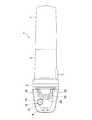
図1は、グラインダの一例を示す縦断面図、図2は平面図で、グラインダ1は、整流子モータ3を収容したモータハウジング2の前方(図1の左側)に、整流子モータ3の出力軸4を軸支する軸受プレート5を介して本発明のハウジングとなるギヤハウジング6を、後方にリヤカバー7を夫々組み付けてなる。8は、モータハウジング2の側面に設けられ、スライド操作によってリヤカバー7内に設けられたスイッチをON/OFFさせるスライドボタンである。
ギヤハウジング6内には、出力軸4が突出すると共に、その出力軸4の前方でスピンドル9が上下方向に軸支されて、出力軸4の先端へ一体に外装された第1ベベルギヤ10と、スピンドル9へ一体に外装された第2ベベルギヤ11との噛合により、出力軸4の回転をスピンドル9へ伝達可能となっている。スピンドル9の下端は、ギヤハウジング6の下方へ突出して、スピンドル9に二面幅同士の嵌合で一体に結合されるインナーフランジ12と、スピンドル9の下端に設けたネジ部に螺合されるアウターフランジ13とによって、円盤状砥石14が直交状に装着可能となっている。Hereinafter, embodiments of the present invention will be described with reference to the drawings.
FIG. 1 is a longitudinal sectional view showing an example of a grinder, FIG. 2 is a plan view, and the grinder 1 is output in front of the
In the
また、ギヤハウジング6の上面には、平面円形状の収容部15が凹設され、その収容部15にロック部材16が設けられている。このロック部材16は、下端が大径部18となるピン17と、ピン17の上端に嵌着される円形状のキャップ19とからなり、ピン17が収容部15の底面に同軸で形成される筒状の保持部20に遊挿され、収容部15の底面とキャップ19との間に外装されたコイルバネ21により、常態ではピン17の大径部18が保持部20の下端に当接する図1の上限位置に付勢されている。一方、第2ベベルギヤ11の上面には、ピン17の大径部18が嵌合可能な凹部22,22・・が、同心円上に3カ所等間隔で形成されている。よって、何れかの凹部22が真下に位置する状態でロック部材16をコイルバネ21の付勢に抗して下方へ押し込むと、大径部18が凹部22に嵌合して第2ベベルギヤ11の回転をロックし、これと一体のスピンドル9の回転もロックできることになる。 Further, a planar circular
一方、出力軸4における軸受プレート5の後方部位には、ファン23が一体に嵌着され、軸受プレート5におけるファン23の外周際には、複数の通気口24,24・・が形成されている。25は、モータハウジング2と軸受プレート5との間で挟持固定され、ファン23の後方外周を覆うバッフルプレートである。
また、ギヤハウジング6の上方及び下方には、複数の排気口26,26・・が夫々穿設される一方、リヤカバー7の後面には、図示しない複数の吸気口が穿設されている。よって、出力軸4の回転に伴ってファン23が回転すると、吸気口から外気が吸い込まれて整流子モータ3を通過し、ファン23を介して通気口24からギヤハウジング6内に至り、排気口26から外部に排出される冷却用空気の流路が形成される。この冷却用空気により整流子モータ3が冷却されることになる。On the other hand, a
Further, a plurality of
そして、ギヤハウジング6には、冷却用空気の流路が形成されるギヤハウジング6内とロック部材16の収容部15とを連通させ、下端が収容部15の底面と同一平面上に位置する誘導手段としての吹出口27が形成されて、ファン23によりギヤハウジング6内に送り込まれた冷却用空気の一部を、収容部15の底面に沿ってロック部材16と交差状(ここでは直交状)に前方へ吹き出し可能としている。なお、キャップ19は、収容部15の内面との間に空気が通過可能な隙間が残る大きさで形成されている。 The
以上の如く構成されたグラインダ1においては、スライドボタン8を操作して整流子モータ3を駆動させると、出力軸4が回転して第1、第2ベベルギヤ10,11を介してスピンドル9が回転する。よって、円盤状砥石14もスピンドル9と一体回転して、被研磨材の研磨が可能となる。
この出力軸4の回転によりファン23が回転して、前述のようにリヤカバー7の吸気口から取り込んだ冷却用空気を、モータハウジング2及びギヤハウジング6を通過させて排気口26及び吹出口27から排出する。このとき、吹出口27から排出される冷却用空気は、収容部15の底面に沿ってロッド部材16のピン17へ直交状に吹き付けられた後、収容部15とキャップ19との隙間を通って外部へ排出されることになる。この冷却用空気の吹き出しにより、収容部15とキャップ19との隙間及びピン17と保持部20との間への粉塵の侵入が防止される。In the grinder 1 configured as described above, when the commutator motor 3 is driven by operating the
The
そして、円盤状砥石14の着脱を行う際は、ロック部材16を下方へ押し込んで下端の大径部18を第2ベベルギヤ11の凹部22に嵌合させれば、スピンドル9の回転がロックされる。よって、スピンドル9の下端に螺合されているアウターフランジ13を緩めて円盤状砥石14を交換等することができる。装着時も同様にロック部材16でスピンドル9の回転をロックすればアウターフランジ13のねじ込みが可能となる。このとき、前述のように冷却用空気の吹き出しによって収容部15側への粉塵の侵入は防止されているため、ロック部材16をスムーズに押し込むことができ、押し込みを解除した際にはコイルバネ21の付勢によりロック部材16は確実に上限位置に復帰する。 When the disk-
このように、上記形態のグラインダ1によれば、ギヤハウジング6に、冷却用空気の一部を導いてギヤハウジング6の外側でロック部材16の設置部位に向けて吹き出させる誘導手段(吹出口27)を設けたことで、ロック部材16の設置部位への粉塵の侵入が効果的に防止される。よって、ロック部材16の好適な操作性が長期に亘って維持可能となり、粉塵の侵入によるロック部材16の損傷等のおそれも解消される。また、整流子モータ3の冷却用空気を合理的に利用するので、誘導手段の採用に係るコストアップも最小限で済む。
特に、誘導手段を、冷却用空気の流路と連通し、ギヤハウジング6の外面に沿って冷却用空気の一部をロック部材16と交差状に吹き出す吹出口27としたことで、吹出口27を設ける簡単な構成で誘導手段が形成可能となる上、粉塵の侵入防止に一層効果的な冷却用空気の吹き出しも可能となる。Thus, according to the grinder 1 of the said form, the guidance means (air outlet 27) which guides a part of cooling air to the
In particular, the
なお、吹出口は一つに限らず、例えばロック部材を囲むように複数箇所設けたり、収容部の底面に設けて上方へ向けて空気を吹き出させたりする等、適宜変更可能である。
また、誘導手段としては、上記吹出口に限定するものではなく、冷却用空気の流路とロック部材との位置関係によっては、ダクト状の通路をハウジングの内部又は外部に形成してロック部材の設置部位に冷却用空気を誘導する構造等も考えられる。勿論このような異なる形態の複数の誘導手段を併設してもよい。
さらに、ロック部材の形態も上記形態に限らず、収容部やキャップがないもの等であっても本発明の採用は可能である。
その他、ロックするギヤもベベルギヤに限らず、スパイラルベベルギヤやヘリカルギヤ等の他のギヤを使用したグラインダでも差し支えない。
Note that the number of outlets is not limited to one, and can be changed as appropriate, for example, by providing a plurality of locations so as to surround the lock member, or by providing air on the bottom surface of the accommodating portion.
Further, the guiding means is not limited to the above-mentioned air outlet, and depending on the positional relationship between the cooling air flow path and the locking member, a duct-shaped passage may be formed inside or outside the housing to A structure for guiding cooling air to the installation site is also conceivable. Of course, a plurality of different types of guiding means may be provided.
Furthermore, the form of the locking member is not limited to the above form, and the present invention can be adopted even if the holding member or the cap is not provided.
In addition, the gear to be locked is not limited to the bevel gear, and a grinder using another gear such as a spiral bevel gear or a helical gear may be used.
1・・グラインダ、2・・モータハウジング、3・・整流子モータ、4・・出力軸、6・・ギヤハウジング、9・・スピンドル、11・・第2ベベルギヤ、14・・円盤状砥石15・・収容部、16・・ロック部材、17・・ピン、19・・キャップ、20・・保持部、21・・コイルバネ、22・・凹部、23・・ファン、26・・排気口、27・・吹出口。
1. ・ Grinder, 2 ・ ・ Motor housing, 3 ・ ・ Commutator motor, 4 ・ ・ Output shaft, 6 ・ ・ Gear housing, 9 ・ Spindle, 11 ・ ・ Second bevel gear, 14 ・ ・
Claims (2)
Translated fromJapanese前記ハウジングに、前記冷却用空気の一部を導いて前記ハウジングの外側で前記ロック部材の設置部位に向けて吹き出させる誘導手段を設けたことを特徴とするグラインダ。In a housing, a spindle with a gear that is rotated and transmitted from the output shaft of the motor is pivotally supported in the vertical direction, and a disc-shaped grindstone can be attached to the lower end of the spindle that projects downward from the housing. The housing is provided with a lock member capable of locking the rotation of the gear and the spindle by being engaged with the gear by a pushing operation into the housing, and the housing provided by the rotation of the fan provided on the output shaft of the motor. A grinder for allowing the cooling air of the motor to pass therethrough,
A grinder provided with guiding means for guiding a part of the cooling air to the housing and blowing out the air toward an installation site of the lock member outside the housing.
The grinder according to claim 1, wherein the guide means is a blower outlet that communicates with a cooling air flow path and blows out a part of the cooling air along the outer surface of the housing in a crossing manner with the lock member.
Priority Applications (1)
| Application Number | Priority Date | Filing Date | Title |
|---|---|---|---|
| JP2005353950AJP2007152526A (en) | 2005-12-07 | 2005-12-07 | Grinder |
Applications Claiming Priority (1)
| Application Number | Priority Date | Filing Date | Title |
|---|---|---|---|
| JP2005353950AJP2007152526A (en) | 2005-12-07 | 2005-12-07 | Grinder |
Publications (1)
| Publication Number | Publication Date |
|---|---|
| JP2007152526Atrue JP2007152526A (en) | 2007-06-21 |
Family
ID=38237513
Family Applications (1)
| Application Number | Title | Priority Date | Filing Date |
|---|---|---|---|
| JP2005353950APendingJP2007152526A (en) | 2005-12-07 | 2005-12-07 | Grinder |
Country Status (1)
| Country | Link |
|---|---|
| JP (1) | JP2007152526A (en) |
Cited By (3)
| Publication number | Priority date | Publication date | Assignee | Title |
|---|---|---|---|---|
| JP2012236243A (en)* | 2011-05-10 | 2012-12-06 | Makita Corp | Electric tool |
| JP2021049629A (en)* | 2019-09-26 | 2021-04-01 | 株式会社マキタ | Electric power tool |
| US11691262B2 (en) | 2019-09-26 | 2023-07-04 | Makita Corporation | Electric power tool |
- 2005
- 2005-12-07JPJP2005353950Apatent/JP2007152526A/enactivePending
Cited By (5)
| Publication number | Priority date | Publication date | Assignee | Title |
|---|---|---|---|---|
| JP2012236243A (en)* | 2011-05-10 | 2012-12-06 | Makita Corp | Electric tool |
| JP2021049629A (en)* | 2019-09-26 | 2021-04-01 | 株式会社マキタ | Electric power tool |
| US11691262B2 (en) | 2019-09-26 | 2023-07-04 | Makita Corporation | Electric power tool |
| JP7365834B2 (en) | 2019-09-26 | 2023-10-20 | 株式会社マキタ | Electric tool |
| US12304052B2 (en) | 2019-09-26 | 2025-05-20 | Makita Corporation | Electric power tool |
Similar Documents
| Publication | Publication Date | Title |
|---|---|---|
| US10556319B2 (en) | Grinder and cover | |
| US10717182B2 (en) | Angle grinder | |
| US11639009B2 (en) | Portable cutting devices | |
| ES2235423T3 (en) | ELECTRICAL TOOL, ESPECIALLY ANGULAR GRINDER. | |
| US8827004B2 (en) | Power tool having off-lock member | |
| US8123596B2 (en) | Power tools | |
| US8037614B2 (en) | Cutting machine | |
| JP6044718B2 (en) | Grinder | |
| JP2009125928A (en) | Hand tool device | |
| JP6881037B2 (en) | Electric tool | |
| JP5061807B2 (en) | Electric cutter | |
| JP2015163421A (en) | Portable cutting machine | |
| WO2020031867A1 (en) | Cover and tool | |
| JP2007152526A (en) | Grinder | |
| JP4936224B2 (en) | Portable cutting machine | |
| CN110023018A (en) | Power tool | |
| JP5447977B2 (en) | Electric tool | |
| JP6717124B2 (en) | Electric tool | |
| JP2007517702A (en) | Bevel quadrant and gearbox louver blower system | |
| WO2013058254A1 (en) | Centerless grinder | |
| JP6534543B2 (en) | Cutting machine | |
| JP7642383B2 (en) | Rotary tools | |
| JP2004330657A (en) | Portable electric cutting machine | |
| JP4120551B2 (en) | Portable electric cutting machine | |
| JP3132627U (en) | Grinding equipment |