JP2007148257A - Image forming apparatus, printer, copying machine, facsimile machine, multifunction machine - Google Patents
Image forming apparatus, printer, copying machine, facsimile machine, multifunction machineDownload PDFInfo
- Publication number
- JP2007148257A JP2007148257AJP2005345754AJP2005345754AJP2007148257AJP 2007148257 AJP2007148257 AJP 2007148257AJP 2005345754 AJP2005345754 AJP 2005345754AJP 2005345754 AJP2005345754 AJP 2005345754AJP 2007148257 AJP2007148257 AJP 2007148257A
- Authority
- JP
- Japan
- Prior art keywords
- image
- image forming
- carrier
- forming apparatus
- unit
- Prior art date
- Legal status (The legal status is an assumption and is not a legal conclusion. Google has not performed a legal analysis and makes no representation as to the accuracy of the status listed.)
- Pending
Links
Images


Landscapes
- Dry Development In Electrophotography (AREA)
- Electrostatic Charge, Transfer And Separation In Electrography (AREA)
- Control Or Security For Electrophotography (AREA)
Abstract
Translated fromJapaneseDescription
Translated fromJapanese本発明は、電子写真技術を用いた画像形成装置と、その画像形成装置が組み込まれているプリンタ、複写装置、ファクシミリ装置、複合機に関する。 The present invention relates to an image forming apparatus using electrophotographic technology, and a printer, a copying apparatus, a facsimile apparatus, and a multifunction machine in which the image forming apparatus is incorporated.
本発明に係る背景技術として、特許文献1(特開2002−328529号公報)には、「二成分現像における高画質化のためにトナーとキャリアの小粒径化やキャリアを低磁化にすることで、特に微紛側のキャリアのスリーブへの保磁力が小さくなり、画像形成中にドラムに付着するキャリア付着を防止する」ことを課題とし、その解決手段として「画像形成装置の設置時及び前記現像材の交換時、現像スリーブ上のキャリアをドラム上に現像する。その際、潜像電位より現像バイアス電位が低い、かぶり取り(Vback)電位で現像する。現像するキャリアの粒度分布の最大値は、画像形成中にドラム上に付着するキャリアの粒度分布の最大値と同等又は大きい。現像するキャリアの総重量は、画像形成中にドラム上に付着するキャリアの総重量と同等又は大きい。」ことが記載されている。 As background art related to the present invention, Patent Document 1 (Japanese Patent Laid-Open No. 2002-328529) discloses that “the toner and carrier have a small particle diameter and the carrier has low magnetization for high image quality in two-component development”. In particular, the coercive force of the carrier on the fine powder side to the sleeve is reduced, preventing the carrier from adhering to the drum during image formation. When the developer is changed, the carrier on the developing sleeve is developed on the drum, and the developing bias potential is lower than the latent image potential, and the developing is performed at the fogging (Vback) potential. Is equal to or larger than the maximum value of the particle size distribution of the carrier deposited on the drum during image formation, and the total weight of the carrier to be developed is the carrier deposited on the drum during image formation. Total weight equal to or larger. "It has been described.
特許文献2(特開2002−207321号公報)には、「(1)キャリア付着,カブリがなく、ドット再現性に優れた高画質画像を長期に渡って維持することが可能な現像剤および現像方法を提供すること、(2)初期から長期に渡り転写効率が高く、廃トナーの低減が可能となる現像剤及び現像方法を提供する」ことを課題とし、その解決手段として「少なくともトナーと磁性キャリアを有する二成分系現像剤において磁性キャリアは粒度分布がシャープでかつ、高抵抗(1012Ω・cm以上)でありかつ、磁気力が30〜100emu/cm3の範囲である低磁気力の磁性キャリアであり、トナーは粒子の丸さと表面の凹凸の形状を制御したものを組み合わせる現像剤を用いる。」ことが記載されている。Patent Document 2 (Japanese Patent Application Laid-Open No. 2002-207321) describes “(1) Developer and development capable of maintaining a high-quality image excellent in dot reproducibility over a long period without carrier adhesion and fogging. And (2) providing a developer and a developing method that have high transfer efficiency from the initial stage for a long period of time and that can reduce waste toner. In a two-component developer having a carrier, the magnetic carrier has a sharp particle size distribution, a high resistance (1012 Ω · cm or more), and a low magnetic force with a magnetic force in the range of30 to 100 emu / cm3 . "It is a magnetic carrier, and the toner uses a developer that combines the roundness of the particles and the shape of the irregularities on the surface."
特許文献3(特開2005−115283号公報)には、「小粒径キャリアの利点を損なうことなく、ハーフトーン画像が改良でき、さらにキャリア付着余裕度を向上でき、画像形成装置の各接触部材を傷つけることがない静電潜像現像剤用キャリア、該キャリアを用いた現像剤、該現像剤を装填した現像装置、該現像剤を収納した現像剤容器、該現像剤容器を搭載した画像形成装置、該現像剤を用いる現像方法、及び該現像剤を保持したプロセスカートリッジを提供する」ことを課題とし、その解決手段として「磁性を有する芯材粒子と該粒子表面を被覆する樹脂層とからなる静電潜像現像剤用キャリアであって、該芯材粒子が、(1)重量平均粒径(Dw)が25〜45μmであり、(2)1KOeにおける磁気モーメントが65〜90Am2/Kgであり、(3)該キャリアを、固定磁石を内蔵した回転スリーブと、該スリーブと隙間1mmを隔てて配置させた電極とからなる測定装置により、直流電圧を印加し測定して得られる絶縁破壊電圧が1000V以上であることを特徴とする静電潜像現像剤用キャリア。」が記載されている。Patent Document 3 (Japanese Patent Laid-Open No. 2005-115283) states that “a halftone image can be improved without impairing the advantage of a small particle carrier, and further, the carrier adhesion margin can be improved, and each contact member of the image forming apparatus can be improved. Carrier for electrostatic latent image developer that does not damage the image, developer using the carrier, developing device loaded with the developer, developer container containing the developer, and image formation equipped with the developer container The object is to provide an apparatus, a developing method using the developer, and a process cartridge holding the developer, and as a means for solving the problem, “from a magnetic core particle and a resin layer covering the particle surface” A carrier for an electrostatic latent image developer, wherein the core particles have (1) a weight average particle diameter (Dw) of 25 to 45 μm, and (2) a magnetic moment at 1 KOe of 65 to 90 Am.2 / Kg, and (3) obtained by measuring the carrier by applying a DC voltage with a measuring device comprising a rotating sleeve with a built-in fixed magnet and an electrode arranged with a 1 mm gap from the sleeve. The electrostatic latent image developer carrier has a dielectric breakdown voltage of 1000 V or higher.
近年、電子写真技術を用いた画像形成装置においては、解像度アップ、ハイライト再現性向上あるいはカラー化などの要望に応えるため、潜像の最小単位(1ドット)の極小化、高密度化が図られており、特にこれらの潜像(ドット)を、忠実に現像できる現像システムの出現が重要な課題となってきている。
そのために、プロセス条件、現像剤(トナー、キャリア)両面から種々の提案がなされている。プロセス面では、現像ギャップの近接化、像担持体(潜像担持体とも言う)である感光体の薄膜化、また、書き込みビーム径の小径化等が有効であるが、コストが高くなること、また、信頼性などの点で依然大きな課題がある。In recent years, in an image forming apparatus using electrophotographic technology, in order to meet demands for higher resolution, improved highlight reproducibility, or colorization, the minimum unit (1 dot) of a latent image has been minimized and increased in density. In particular, the emergence of development systems capable of faithfully developing these latent images (dots) has become an important issue.
For this purpose, various proposals have been made in terms of both process conditions and developer (toner, carrier). In terms of the process, it is effective to make the development gap close, to make the image carrier (also referred to as a latent image carrier) thin, and to reduce the writing beam diameter, but the cost increases. In addition, there are still major issues in terms of reliability.
一方、現像剤として小粒径トナーを使用すると、ドットの再現性が大幅に改良されるが、その反面、小粒径トナーを含む現像剤には、地汚れの発生、画像濃度の不足などの解決すべき課題が残っている。
また、小粒径のフルカラートナーの場合、充分な色調を得るため、低軟化点の樹脂が使用されるが、黒トナーの場合に比べて、キャリアへのスペント量が多くなり、現像剤が劣化して、トナー飛散および地肌汚れが起こり易くなる。On the other hand, the use of a small particle size toner as a developer greatly improves the dot reproducibility. On the other hand, a developer containing a small particle size toner has a background stain, a lack of image density, etc. There are still issues to be solved.
In the case of a full color toner with a small particle size, a resin with a low softening point is used in order to obtain a sufficient color tone, but the spent amount to the carrier is increased and the developer is deteriorated as compared with the case of a black toner. As a result, toner scattering and background staining are likely to occur.
また、キャリアが小粒径の場合には、次のような利点があることが知られている。
(1)単位重量当たりの表面積が広いため、個々のトナーに充分な摩擦帯電を与えることができ、低帯電量トナー、逆帯電量トナーの発生が少ない。その結果、地汚れが発生しにくくなり、また、ドット周辺のトナーの散りとか滲みが少なく、ドット再現性が良好となる。
(2)単位重量当たりの表面積が広く、地汚れが発生しにくいことから、トナーの平均帯電量を低くすることができ、充分な画像濃度が得られる。従って、小粒径キャリアは、小粒径トナー使用時の不具合点を補うことが可能であり、小粒径トナーの利点を引き出すのに特に有効である。
(3)小粒径キャリアは、緻密な磁気ブラシを形成し、かつ穂の流動性が良いため、画像に穂跡が発生しにくいという特徴がある。In addition, it is known that there are the following advantages when the carrier has a small particle diameter.
(1) Since the surface area per unit weight is wide, sufficient frictional charge can be given to each toner, and the generation of low charge amount toner and reverse charge amount toner is small. As a result, background stains are less likely to occur, and toner scattering and bleeding around the dots are reduced, resulting in good dot reproducibility.
(2) Since the surface area per unit weight is large and scumming is less likely to occur, the average charge amount of the toner can be reduced and a sufficient image density can be obtained. Therefore, the small particle size carrier can make up for problems in using the small particle size toner, and is particularly effective in drawing out the advantages of the small particle size toner.
(3) The small particle size carrier is characterized in that it forms a dense magnetic brush and the flowability of the ears is good, so that the traces of the ears are hardly generated in the image.
しかしながら、従来、小粒径キャリアは、キャリア付着あるいはキャリア飛散が発生し易いことが非常に大きな問題であり、さらに、像担持体である感光体の傷や定着ローラ傷の発生原因となっていたので、実用化が難しかった。 However, conventionally, a small particle size carrier has a very big problem that carrier adhesion or carrier scattering is likely to occur, and further, it has been a cause of scratches on a photoconductor as an image carrier and flaws on a fixing roller. Therefore, practical application was difficult.
また、飽和磁化の小さいキャリアを使用することによって高画質が達成できるということも知られており、最近では飽和磁化の小さいキャリアを用いることが一般的となっている。
しかしながら、単純に飽和磁化の小さなキャリアを使用することで銅線の再現性は向上するが、一方で現像スリーブ上でのキャリア粒子の拘束力が低下するために感光ドラム上にキャリアが移行して画像欠陥を発生させてしまう、いわゆるキャリア付着現象が発生しやすくなる。It is also known that high image quality can be achieved by using carriers with small saturation magnetization, and recently, it has become common to use carriers with small saturation magnetization.
However, simply using a carrier with a small saturation magnetization improves the reproducibility of the copper wire, but on the other hand, the carrier particles move on the photosensitive drum because the binding force of the carrier particles on the developing sleeve decreases. A so-called carrier adhesion phenomenon that causes an image defect is likely to occur.
従来の技術では、飽和磁化に関する特性値を規定値以内にするというものがよく見受けられる。それゆえに、キャリア製造工程では厳密に飽和磁化特性の管理が行われている。しかし、キャリア一粒一粒について見ていった場合、全ての粒を規定値以内に保つことは現実的には困難であってコスト高を招く。しかし、実画像において、一粒のキャリアででもキャリア付着があった場合、白抜けが発生し、それがハーフトーン画像ならば、はっきりと異常画像だと認識されるものになる。
その結果、新品のキャリアを用いたときに、僅かながらの規格外キャリア成分によってキャリア付着が発生しやすくなる。そして、このキャリア付着は、現像剤を使い込むにつれて減少するのは言うまでもない。しかし、初期時において、キャリア付着による白抜け画像を確認すると、その製品に対する信頼が損なわれてしまう。In the prior art, it is often seen that the characteristic value related to saturation magnetization is within a specified value. Therefore, the saturation magnetization characteristic is strictly managed in the carrier manufacturing process. However, when looking at each carrier, it is actually difficult to keep all the grains within the specified value, resulting in high costs. However, in the actual image, when carrier adheres even with a single carrier, white spots occur, and if it is a halftone image, it is clearly recognized as an abnormal image.
As a result, when a new carrier is used, carrier adhesion tends to occur due to slight non-standard carrier components. Needless to say, this carrier adhesion decreases as the developer is used. However, at the initial stage, if a blank image due to carrier adhesion is confirmed, the reliability of the product is impaired.
本発明は、上記のことを鑑みて、新品のキャリアにおける初期キャリア付着を低減させるためになされたものである。
ここで、前述の特許文献1に記載の従来技術では、画像形成装置の設置時や現像剤の交換時等、新品の現像剤を使用するときに、規格外のキャリアを吐き出す動作を行っている。これを、感光体帯電ポテンシャルを現像バイアスよりも高くするというかぶり取り電位でキャリアを現像することにより行っている。この場合、キャリア現像効率を上げるには、かぶり取り電位を高くしなければならず、このときに規格内のキャリアも多く現像してしまう。
さらに、エッジ効果によるキャリア付着という問題もあり、これは露光部と非露光部との界面においてキャリア付着が発生しやすい現象だが、通常のかぶり取り電位でキャリア現像を行って除去するだけでは、この現象を抑止することは出来ない。In view of the above, the present invention has been made to reduce initial carrier adhesion in a new carrier.
Here, in the prior art described in
In addition, there is a problem of carrier adhesion due to the edge effect, which is a phenomenon in which carrier adhesion is likely to occur at the interface between the exposed area and the non-exposed area. The phenomenon cannot be suppressed.
本発明では、これらの問題を解決し、この方法よりも時間的効率がよく、さらに規格内キャリアの現像を低減する構成を与えることを課題としている。
ここで、前述の特許文献2に記載の従来技術では、磁性キャリアの粒度分布、抵抗値、磁気力の仕様を与えているだけで、本発明の課題については触れていない。
また、前述の特許文献3に記載の従来技術では、磁性キャリアの粒径、磁気モーメント、絶縁破壊電圧の仕様を与えているだけで、本発明の課題については触れていない。An object of the present invention is to solve these problems and to provide a configuration that is more time efficient than this method and further reduces the development of carriers within the standard.
Here, in the prior art described in
In addition, the prior art described in
本発明は以上の点に鑑みてなされたものであり、その目的は、トナーとキャリアで構成された2成分現像剤を用いた画像形成装置において、新品の現像剤における初期のキャリアの感光体上への付着を防止することにある。 The present invention has been made in view of the above points. An object of the present invention is to provide an image forming apparatus using a two-component developer composed of a toner and a carrier, on a photoreceptor of an initial carrier in a new developer. It is to prevent adhesion to the surface.
より詳しく述べると、本発明の第1の目的は、エッジ効果によってキャリア付着しやすいキャリアを除去して、キャリア製造工程による製造コストを上げることなく、新品のキャリアの初期時における感光体へのキャリア付着を容易に低減させることが可能な画像形成装置を提供することである。
本発明の第2の目的は、第1の目的に加え、記録媒体を浪費させない構成の画像形成装置を提供することである。
本発明の第3の目的は、第1の目的に加え、キャリア付着しやすいキャリアの除去を効率的に行うことができる画像形成装置を提供することである。
本発明の第4の目的は、第1の目的に加え、キャリア付着しやすいキャリアの除去を効率的に行うことができる画像形成装置を提供することである。
本発明の第5の目的は、第1の目的に加え、プレ作像動作中による転写装置の汚れを防止することができる画像形成装置を提供することである。
本発明の第6の目的は、第1の目的に加え、プレ作像動作中による転写装置の汚れを防止することができる画像形成装置を提供することである。
本発明の第7の目的は、第1の目的に加えて、キャリア付着を起こしやすい新品キャリアの検知をもれなく行うことができる画像形成装置を提供することである。
本発明の第8の目的は、第1の目的に加え、同一のキャリアに対して2回以上プレ作像動作を行うことを防止することができる画像形成装置を提供することである。
本発明の第9の目的は、第1の目的に加え、キャリア付着しやすいキャリアの除去を効率的に行うことができる画像形成装置を提供することである。
本発明の第10の目的は、第1の目的に加え、プレ作像動作におけるトナー消費量を少なくすることができる画像形成装置を提供することである。
本発明の第11の目的は、キャリア付着しやすいキャリアを除去して、キャリア製造工程による製造コストを上げることなく、新品のキャリアの初期時における像担持体(例えば感光体)へのキャリア付着を容易に低減させることが可能なプリンタ、複写装置、ファクシミリ装置、複合機を提供することである。More specifically, the first object of the present invention is to remove a carrier that is likely to adhere to the carrier due to the edge effect, and to increase the manufacturing cost of the carrier manufacturing process, so that the carrier to the photoreceptor at the initial stage of a new carrier is obtained. An object of the present invention is to provide an image forming apparatus capable of easily reducing adhesion.
In addition to the first object, a second object of the present invention is to provide an image forming apparatus having a configuration that does not waste a recording medium.
In addition to the first object, a third object of the present invention is to provide an image forming apparatus capable of efficiently removing a carrier that easily adheres to a carrier.
In addition to the first object, a fourth object of the present invention is to provide an image forming apparatus capable of efficiently removing a carrier that easily adheres to a carrier.
In addition to the first object, a fifth object of the present invention is to provide an image forming apparatus capable of preventing the transfer device from being soiled during the pre-image forming operation.
In addition to the first object, a sixth object of the present invention is to provide an image forming apparatus capable of preventing the transfer device from being soiled during the pre-image forming operation.
In addition to the first object, a seventh object of the present invention is to provide an image forming apparatus capable of detecting all new carriers that easily cause carrier adhesion.
In addition to the first object, an eighth object of the present invention is to provide an image forming apparatus capable of preventing a pre-image forming operation from being performed twice or more on the same carrier.
In addition to the first object, a ninth object of the present invention is to provide an image forming apparatus capable of efficiently removing a carrier that easily adheres to a carrier.
In addition to the first object, a tenth object of the present invention is to provide an image forming apparatus that can reduce the amount of toner consumed in the pre-image forming operation.
The eleventh object of the present invention is to remove the carrier that is likely to adhere to the carrier, and to prevent the carrier from adhering to the image carrier (for example, the photoreceptor) at the initial stage of the new carrier without increasing the production cost of the carrier production process. It is an object of the present invention to provide a printer, a copying machine, a facsimile machine, and a multifunction machine that can be easily reduced.
前記目的を達成するため、本発明では以下のような手段を採っている。
本発明の第1の手段は、像担持体と、前記像担持体に潜像を形成するための潜像形成手段と、前記潜像が形成された像担持体上にトナー画像を形成するためのトナーとキャリアを併せ持った現像剤を有する現像装置と、前記像担持体上のトナー画像を記録媒体或いは中間転写体に転写させる転写装置とを備えた画像形成装置において、前記現像装置には、前記現像装置内のキャリアが新品であるかどうかの情報をもった新品情報素子が備えられ、前記新品情報素子より前記現像装置内のキャリアが新品であると判断された場合には、前記潜像形成手段により前記像担持体に所定のハーフトーンパターンの潜像を形成し、前記現像装置によって前記潜像をトナー画像とするプレ作像動作を一定時間継続して行うことを特徴とする(請求項1)。In order to achieve the above object, the present invention adopts the following means.
According to a first aspect of the present invention, an image carrier, a latent image forming unit for forming a latent image on the image carrier, and a toner image on the image carrier on which the latent image is formed. In the image forming apparatus comprising a developing device having a developer having both toner and a carrier and a transfer device for transferring the toner image on the image carrier to a recording medium or an intermediate transfer member, the developing device includes: A new information element having information on whether or not the carrier in the developing device is new is provided, and when the carrier in the developing device is determined to be new from the new information element, the latent image A latent image having a predetermined halftone pattern is formed on the image carrier by a forming unit, and a pre-image forming operation using the latent image as a toner image is continuously performed for a predetermined time by the developing device. Item 1).
本発明の第2の手段は、第1の手段の画像形成装置において、前記プレ作像動作を行うときには、前記記録媒体の搬送を行わないことを特徴とする(請求項2)。
また、本発明の第3の手段は、第1または第2の手段の画像形成装置において、前記プレ作像動作を行うときには、前記像担持体の帯電電位を当該画像形成装置の許容最大値とすることを特徴とする(請求項3)。The second means of the present invention is characterized in that in the image forming apparatus of the first means, the recording medium is not conveyed when the pre-image forming operation is performed.
According to a third means of the present invention, when the pre-image forming operation is performed in the image forming apparatus of the first or second means, the charging potential of the image carrier is set to the allowable maximum value of the image forming apparatus. (Claim 3).
本発明の第4の手段は、第1乃至第3のいずれか一つの手段の画像形成装置において、前記プレ作像動作を行うときには、現像バイアスと像担持体帯電電位との差を、通常の画像作像動作のときよりも大きいか或いは同等とすることを特徴とする(請求項4)。
また、本発明の第5の手段は、第1乃至第4のいずれか一つの手段の画像形成装置において、前記プレ作像動作を行うときには、前記像担持体と前記転写装置とを離間させることを特徴とする(請求項5)。According to a fourth means of the present invention, in the image forming apparatus of any one of the first to third means, when the pre-image forming operation is performed, the difference between the developing bias and the image carrier charging potential is calculated as a normal value. It is larger than or equal to that in the image forming operation (claim 4).
According to a fifth means of the present invention, in the image forming apparatus of any one of the first to fourth means, the image carrier and the transfer device are separated when the pre-image forming operation is performed. (Claim 5).
本発明の第6の手段は、第1乃至第5のいずれか一つの手段の画像形成装置において、前記プレ作像動作を行うときには、前記像担持体と前記転写装置とに印加される転写バイアスを切る或いは逆バイアスをかけることを特徴とする(請求項6)。
また、本発明の第7の手段は、第1乃至第6のいずれか一つの手段の画像形成装置において、前記新品情報素子の情報は、通常の画像作像動作の前に毎回検知されることを特徴とする(請求項7)。
さらに、本発明の第8の手段は、第1乃至第7のいずれか一つの手段の画像形成装置において、前記プレ作像動作を行った後には、該新品情報素子の情報を、新品ではないという情報に書き換えることを特徴とする(請求項8)。According to a sixth means of the present invention, in the image forming apparatus of any one of the first to fifth means, the transfer bias applied to the image carrier and the transfer device when the pre-image forming operation is performed. Or reverse biasing. (Claim 6).
According to a seventh means of the present invention, in the image forming apparatus of any one of the first to sixth means, the information of the new information element is detected every time before a normal image forming operation. (Claim 7).
Further, according to an eighth means of the present invention, in the image forming apparatus of any one of the first to seventh means, after performing the pre-image forming operation, the information of the new information element is not new. This information is rewritten as (claim 8).
本発明の第9の手段は、第1乃至第8のいずれか一つの手段の画像形成装置において、前記ハーフトーンパターンの網点のサイズは、少なくとも2画素以上の幅及び高さであることを特徴とする(請求項9)。
また、本発明の第10の手段は、第1乃至第9のいずれか一つの手段の画像形成装置において、前記ハーフトーンパターンのトナー画像面積率は、50%以下であることを特徴とする。
さらに、本発明の第11の手段は、第1乃至第10のいずれか一つに記載の画像形成装置において、前記像担持体は光を照射することによって潜像が形成される光導電性の感光体であり、前記潜像形成手段は画像情報に応じて前記感光体に光を照射して潜像を形成する光学記録手段であることを特徴とする(請求項11)。According to a ninth means of the present invention, in the image forming apparatus of any one of the first to eighth means, the halftone pattern halftone dot size is a width and height of at least two pixels or more. It is characterized (claim 9).
According to a tenth means of the present invention, in the image forming apparatus of any one of the first to ninth means, a toner image area ratio of the halftone pattern is 50% or less.
Further, according to an eleventh means of the present invention, in the image forming apparatus according to any one of the first to tenth aspects, the image carrier is a photoconductive material on which a latent image is formed by irradiating light. The latent image forming means is an optical recording means for forming a latent image by irradiating light to the photoconductor in accordance with image information.
本発明の第12の手段は、プリンタであって、装置外部から入力された画像情報に応じて画像を形成する画像形成部を備え、該画像形成部に第1乃至第11のいずれか一つの手段の画像形成装置が組み込まれていることを特徴とする(請求項12)。
また、本発明の第13の手段は、複写装置であって、原稿画像を読取る画像読取部と、該画像読取部で読取った画像情報に応じて画像を形成する画像形成部を備え、該画像形成部に第1乃至第11のいずれか一つの手段の画像形成装置が組み込まれていることを特徴とする(請求項13)。A twelfth means of the present invention is a printer, comprising an image forming unit that forms an image in accordance with image information input from outside the apparatus, and the image forming unit includes any one of the first to eleventh aspects. An image forming apparatus is incorporated therein (claim 12).
According to a thirteenth aspect of the present invention, there is provided a copying apparatus including an image reading unit that reads an original image and an image forming unit that forms an image according to image information read by the image reading unit. The image forming apparatus of any one of the first to eleventh means is incorporated in the forming portion (claim 13).
本発明の第14の手段は、ファクシミリ装置であって、原稿画像を読取る画像読取部と、該画像読取部で読取った画像情報を送信する機能及び画像情報を受信する機能を有する通信手段と、前記画像読取部で読取った画像情報或いは前記通信手段で受信した画像情報に応じて画像を形成する画像形成部を備え、該画像形成部に請求項1乃至11のいずれか一つに記載の画像形成装置が組み込まれていることを特徴とする(請求項14)。
また、本発明の第15の手段は、複合機であって、原稿画像を読取る画像読取部と、該画像読取部で読取った画像情報を送信する機能及び画像情報を受信する機能を有する通信手段と、前記画像読取部で読取った画像情報或いは前記通信手段で受信した画像情報もしくは装置外部から入力された画像情報に応じて画像を形成する画像形成部を備え、該画像形成部に請求項1乃至11のいずれか一つに記載の画像形成装置が組み込まれていることを特徴とする(請求項15)。A fourteenth means of the present invention is a facsimile apparatus, an image reading section for reading a document image, a communication means having a function for transmitting image information read by the image reading section and a function for receiving image information, The image forming unit according to
According to a fifteenth aspect of the present invention, there is provided an image reading unit for reading a document image, a communication unit having a function for transmitting image information read by the image reading unit and a function for receiving image information. And an image forming unit that forms an image in accordance with image information read by the image reading unit, image information received by the communication unit, or image information input from outside the apparatus, and the image forming unit includes: The image forming apparatus according to any one of claims 11 to 11 is incorporated (claim 15).
本発明に係る画像形成装置では、像担持体(例えば、光を照射することによって潜像が形成される光導電性の感光体)と、前記像担持体に潜像を形成するための潜像形成手段(例えば、画像情報に応じて感光体に光を照射して潜像を形成する光学記録手段)と、前記潜像が形成された感光体上にトナー画像を形成するためのトナーとキャリアを併せ持った現像剤を有する現像装置と、前記感光体上のトナー画像を記録媒体或いは中間転写体に転写させる転写装置とを備えた画像形成装置において、前記現像装置には、前記現像装置内のキャリアが新品であるかどうかの情報をもった新品情報素子が備えられ、前記新品情報素子より前記現像装置内のキャリアが新品であると判断された場合には、前記光学記録手段により前記感光体に所定のハーフトーンパターンの潜像を形成し、前記現像装置によって前記潜像をトナー画像とするプレ作像動作を一定時間継続して行うことにより、エッジ効果によってキャリア付着しやすいキャリアを除去して、キャリア製造工程による製造コストを上げることなく、新品のキャリアの初期時における感光体へのキャリア付着を容易に低減させることが可能になる。 In the image forming apparatus according to the present invention, an image carrier (for example, a photoconductive photosensitive member on which a latent image is formed by irradiating light) and a latent image for forming a latent image on the image carrier. Forming means (for example, optical recording means for forming a latent image by irradiating light to the photoconductor according to image information), and toner and carrier for forming a toner image on the photoconductor on which the latent image is formed In the image forming apparatus, the developing device includes a developing device having a developer having both, and a transfer device that transfers the toner image on the photosensitive member to a recording medium or an intermediate transfer member. A new information element having information on whether or not the carrier is new is provided, and when the carrier in the developing device is determined to be new from the new information element, the optical recording means performs the photoconductor. The prescribed ha By forming a latent image of a tone pattern and continuously performing a pre-image forming operation using the latent image as a toner image by the developing device for a certain period of time, the carrier that easily adheres to the carrier is removed by the edge effect, and the carrier It is possible to easily reduce carrier adhesion to the photosensitive member at the initial stage of a new carrier without increasing the manufacturing cost due to the manufacturing process.
本発明に係る画像形成装置では、前記構成に加えて、前記プレ作像動作を行うときには、記録媒体の搬送を行わないので、記録媒体の浪費を防止することが可能になる。
また、本発明に係る画像形成装置では、前記構成に加えて、前記プレ作像動作を行うときには、感光体帯電電位を当該画像形成装置の許容最大値としているので、キャリア付着しやすいキャリアの除去を効率的に行うことが可能になる。In the image forming apparatus according to the present invention, in addition to the above configuration, when the pre-image forming operation is performed, since the recording medium is not transported, it is possible to prevent the recording medium from being wasted.
In the image forming apparatus according to the present invention, in addition to the above configuration, when the pre-image forming operation is performed, the photosensitive member charging potential is set to the allowable maximum value of the image forming apparatus. Can be performed efficiently.
本発明に係る画像形成装置では、前記構成に加えて、前記プレ作像動作を行うときには、現像バイアスと感光体帯電電位との差を、通常の画像作像動作のときよりも大きいか或いは同等としたことにより、キャリア付着しやすいキャリアの除去を効率的に行うことが可能になる。
また、本発明に係る画像形成装置では、前記構成に加えて、前記プレ作像動作を行うときには、該感光体と該転写装置とを離間させることにより、プレ作像動作中による転写装置の汚れを防止することが可能になる。In the image forming apparatus according to the present invention, in addition to the above configuration, when the pre-image forming operation is performed, the difference between the developing bias and the photosensitive member charging potential is greater than or equal to that in the normal image forming operation. By doing so, it becomes possible to efficiently remove the carrier that easily adheres to the carrier.
Further, in the image forming apparatus according to the present invention, in addition to the above configuration, when the pre-image forming operation is performed, the photosensitive member and the transfer device are separated from each other so that the transfer device becomes dirty during the pre-image forming operation. Can be prevented.
本発明に係る画像形成装置では、前記構成に加えて、前記プレ作像動作を行うときには、該感光体と該転写装置との転写バイアスを切る或いは逆バイアスをかけることにより、プレ作像動作中による転写装置の汚れを防止することが可能になる。
また、本発明に係る画像形成装置では、前記構成に加えて、前記新品情報素子の情報は、通常の画像作像動作の前に毎回検知されることにより、キャリア付着を起こしやすい新品のキャリアの検知をもれなく行うことが可能になる。
さらに、本発明に係る画像形成装置では、前記構成に加えて、前記プレ作像動作を行った後には、前記新品情報素子の情報を、新品ではないという情報に書き換えることにより、同一のキャリアに対して2回以上プレ作像動作を行うことを防止することが可能になる。In the image forming apparatus according to the present invention, in addition to the above configuration, when performing the pre-image forming operation, the transfer bias between the photoconductor and the transfer device is turned off or a reverse bias is applied to perform the pre-image forming operation. This makes it possible to prevent the transfer device from being soiled.
Further, in the image forming apparatus according to the present invention, in addition to the above-described configuration, the information of the new information element is detected every time before the normal image forming operation. It is possible to perform detection without fail.
Further, in the image forming apparatus according to the present invention, in addition to the above configuration, after performing the pre-imaging operation, the information of the new information element is rewritten to information that is not new so that the same carrier can be used. On the other hand, it is possible to prevent the pre-imaging operation from being performed twice or more.
本発明に係る画像形成装置では、前記構成に加えて、前記ハーフトーンパターンの網点のサイズを、少なくとも2画素以上の幅及び高さとしたことにより、キャリア付着しやすいキャリアの除去を効率的に行うことが可能になる。
また、本発明に係る画像形成装置では、前記構成に加えて、前記ハーフトーンパターンのトナー画像面積率を、50%以下としたことにより、プレ作像動作におけるトナー消費量を少なく抑えることが可能になる。In the image forming apparatus according to the present invention, in addition to the above-described configuration, the halftone pattern halftone dot has a width and height of at least two pixels, thereby efficiently removing the carrier that easily adheres to the carrier. It becomes possible to do.
Further, in the image forming apparatus according to the present invention, in addition to the above configuration, the toner image area ratio of the halftone pattern is set to 50% or less, so that it is possible to reduce the amount of toner consumed in the pre-image forming operation. become.
本発明に係るプリンタまたは複写装置またはファクシミリ装置あるいは複合機では、画像形成部に前記のいずれかの構成の画像形成装置が組み込まれているので、エッジ効果によってキャリア付着しやすいキャリアを除去して、キャリア製造工程による製造コストを上げることなく、新品のキャリアの初期時における感光体へのキャリア付着を容易に低減させることができ、新品の現像剤を用いた初期時から、良好な画像を得ることが可能になる。 In the printer, the copying machine, the facsimile machine, or the multifunction machine according to the present invention, since the image forming apparatus having any of the above-described structures is incorporated in the image forming unit, the carrier that easily adheres to the carrier due to the edge effect is removed, Without increasing the manufacturing cost of the carrier manufacturing process, it is possible to easily reduce carrier adhesion to the photoreceptor at the initial stage of a new carrier, and to obtain a good image from the initial stage using a new developer. Is possible.
以下、本発明の構成、動作及び作用効果について、図示の実施例に基づいて詳細に説明する。 Hereinafter, the configuration, operation, and effects of the present invention will be described in detail based on the illustrated embodiments.
本発明は、像担持体と、前記像担持体に潜像を形成するための潜像形成手段と、前記潜像が形成された像担持体上にトナー画像を形成するためのトナーとキャリアを併せ持った現像剤を有する現像装置と、前記像担持体上のトナー画像を記録媒体或いは中間転写体に転写させる転写装置とを備えた画像形成装置と、その画像形成装置を画像形成部に組み込んだプリンタ、複写装置、ファクシミリ装置、複合機に関するものである。ここで、以下の実施例では、像担持体は光を照射することによって潜像が形成される光導電性の感光体とし、潜像形成手段は画像情報に応じて前記感光体に光を照射して潜像を形成する光学記録手段とする。 The present invention relates to an image carrier, a latent image forming unit for forming a latent image on the image carrier, and a toner and a carrier for forming a toner image on the image carrier on which the latent image is formed. An image forming apparatus comprising a developing device having a developer and a transfer device for transferring a toner image on the image carrier to a recording medium or an intermediate transfer member, and the image forming device incorporated in an image forming unit The present invention relates to a printer, a copying machine, a facsimile machine, and a multifunction machine. Here, in the following embodiments, the image carrier is a photoconductive photosensitive member on which a latent image is formed by irradiating light, and the latent image forming unit irradiates the photosensitive member with light according to image information. Thus, an optical recording means for forming a latent image is obtained.
図1に画像形成装置の全体構成の概略を示す。図1ではフルカラー画像形成装置の例で示してある。フルカラー印刷を行うための画像形成装置は、図中の左から順にイエロー(Y),マゼンタ(M),シアン(C),ブラック(K)の4色のカラーユニットを有し、それぞれのカラーユニットは感光体1と現像装置3などの構成部材を有しており、それぞれの感光体1に個別の潜像を形成するように、光学記録手段2は少なくとも4本の光ビームを有している。なお、図中の左から順に配置されたイエロー(Y),マゼンタ(M),シアン(C),ブラック(K)の4色のカラーユニットの構成は同じであり、同じ構成部材には同一の符号を付けて、各構成部材の符号の後に対応する色の記号Y,M,C,Kを付けているが、4色のカラーユニットの構成は同じなので、以下の説明では色の記号は省略する。 FIG. 1 shows an outline of the overall configuration of the image forming apparatus. FIG. 1 shows an example of a full-color image forming apparatus. An image forming apparatus for performing full color printing has four color units of yellow (Y), magenta (M), cyan (C), and black (K) in order from the left in the figure, and each color unit. Has components such as the
近年では、記録速度を上げるために1ユニットに対して複数のビームを用いる構成も増えており、したがって、その場合は、全ユニットで相応のビーム数となる。なお、光学記録手段2については走査法は特に限定はしない。例えば、ビームプロファイルが一直線になるようなラインヘッド(例えば発光ダイオード(LED)アレイとレンズアレイを組み合わせたもの等)の光学系も存在はするが、ここでは最も一般的なレーザ光源と光偏向器(ポリゴンミラー)及び走査結像光学系を用いたポリゴン走査法で説明を進める。 In recent years, a configuration in which a plurality of beams are used for one unit in order to increase the recording speed has been increased. Therefore, in this case, the number of beams is appropriate for all units. The scanning method for the optical recording means 2 is not particularly limited. For example, there is an optical system of a line head (for example, a combination of a light emitting diode (LED) array and a lens array) in which the beam profile is in a straight line, but here the most common laser light source and optical deflector The description proceeds with a polygon scanning method using a (polygon mirror) and a scanning imaging optical system.
ポリゴン走査法は、複数の偏向反射面を有するポリゴンミラー(回転多面鏡とも言う)2−1を高速回転させて、4つのレーザ光源(例えば半導体レーザ)2−2からの光ビームを各感光体1の軸方向(主走査方向)に偏向走査し、走査結像光学系(図示省略)を介して各感光体1に光ビームを照射してライン状の潜像形成を繰り返し行い、感光体1の回転方向を副走査として記録を行う方法である。記録は4色について行わなければならないが、図示のようにポリゴンミラー2−1を中央に置いて、その左右に2組づつ光源と光学系を振り分けて配置することにより、1個のみのポリゴンミラー2−1でも構成は可能である。また、ポリゴンミラーを図示のように中央に配置する場合は、ポリゴンミラーを2個に重ねて用いてもよい。また、4段に重ねたポリゴンミラーを光学記録手段2の片側に配置し、4段のポリゴンミラーで各カラーユニットごとに走査する片側走査方式とする方法でもかまわない。さらには、1組の光源とポリゴンミラー及び光学系からなる光学記録手段を各カラーユニットごとに設ける構成でもかまわない。 In the polygon scanning method, a polygon mirror (also referred to as a rotating polygon mirror) 2-1 having a plurality of deflecting and reflecting surfaces is rotated at high speed, and light beams from four laser light sources (for example, semiconductor lasers) 2-2 are transferred to the respective photosensitive members. 1 is deflected and scanned in the axial direction (main scanning direction) 1, and each
4つのカラーユニット内にそれぞれ配置されるイエロー(Y),マゼンタ(M),シアン(C),ブラック(K)の各色に対応する現像装置3は、収納する現像剤のトナーの色が異なるだけで構成は同じであり、感光体上にトナー画像を形成させるべくトナーを感光体1に供給する現像ローラ3−1を備えている。また、ここではイエロー(Y)の現像装置3にのみ符号を付けているが、現像装置内には、現像剤を攪拌してトナーに電荷をもたせるための攪拌ローラ3−2と、現像ローラ上の現像剤の層の厚みを均一にするドクタブレード3−3を備えている。
現像剤は磁性体からなるキャリアと、トナーの二成分で構成されており、現像剤がこの二成分タイプの場合、攪拌ローラ3−3はキャリアとトナーを全体的に一様に攪拌・混合し、摩擦帯電させる役割を持っている。The developing
The developer is composed of two components, a carrier made of a magnetic material and a toner. When the developer is of this two-component type, the stirring roller 3-3 stirs and mixes the carrier and the toner uniformly throughout. , Has the role of triboelectric charging.
現像ローラ3−1は磁力を持っており、それによってキャリアが現像ローラに保持されている。一例としては、現像ローラ3−1は、円筒状の非磁性体からなり周方向に回転するスリーブと、そのスリーブの内部に配置され固定された複数の磁石(または複数の磁極が着磁されたマグネットローラ)とからなり、磁石(またはマグネットローラの磁極)の発する磁力によりキャリアが吸引されスリーブ上に保持される。また、現像装置内では、攪拌ローラ3−3によってキャリアとトナーが攪拌・混合されて摩擦帯電しているので、前記スリーブ上に保持されるキャリアの周囲にはトナーが静電的に付着しており、キャリアとともにトナーもスリーブ上に保持されている。そして、現像ローラ3−1のスリーブ上に保持された現像剤(キャリとトナー)は、スリーブの回転によって感光体1に向けて搬送され、その搬送過程で前記ドクタブレード3−3によって層厚を均一にされた後、感光体との対向領域である現像領域に至る。そして現像領域に入った現像剤は、該現像領域に配置されている主磁石(またはマグネットローラの主磁極)の磁力によってキャリアが穂立ちし、所謂磁気ブラシが構成され、その中に一定の濃度でトナーが搬送される。なお、現像領域では、感光体1は現像ローラ3−1のスリーブと一定のギャップを持って設けられており、感光体1と現像ローラ3−1間には所定の現像バイアスが印加され、磁気ブラシの先端側のトナーが感光体上の潜像に静電的に付着して現像を行う。 The developing roller 3-1 has a magnetic force, whereby the carrier is held by the developing roller. As an example, the developing roller 3-1 includes a sleeve made of a cylindrical nonmagnetic material and rotating in the circumferential direction, and a plurality of magnets (or a plurality of magnetic poles) arranged and fixed inside the sleeve. The carrier is attracted and held on the sleeve by the magnetic force generated by the magnet (or the magnetic pole of the magnet roller). In the developing device, since the carrier and toner are agitated and mixed by the agitating roller 3-3 and frictionally charged, the toner is electrostatically attached around the carrier held on the sleeve. The toner is held on the sleeve together with the carrier. The developer (carry and toner) held on the sleeve of the developing roller 3-1 is conveyed toward the
各カラーユニットの感光体1の周囲には、上記の現像装置3の他、感光体表面を帯電させるための帯電装置(例えば帯電ローラ)1−1や、感光体表面をクリーニングするためのクリーニング装置(例えばトナークリーニングブレード)1−2などが設けられている。また、必要があれば、感光体表面を除電する除電用LED1−3や、滑剤1−4と滑剤塗布ローラ1−5等も設けられる。なお、ここでは帯電装置1−1を帯電ローラ、クリーニング装置1−2をトナークリーニングブレードとするが、帯電装置としては、帯電ローラの他、帯電ブラシ、帯電チャージャ等を用いることができる。また、クリーニング装置1−2もクリーニングブレードの他、クリーニングブラシやクリーニングローラ等を用いることができる。 Around the
帯電ローラ1−1による帯電、光学記録手段2による画像情報に応じた光照射によって各感光体1に形成された静電潜像は、各現像装置3の各色のトナーでそれぞれ現像されて可視像化される。そして、各感光体1上に形成された各色のトナー画像は、一つの転写装置4に転写される。すなわち、各色の画像がここで重ね合わせられるので、この段階で正確な色合わせが必要となる。 The electrostatic latent image formed on each
転写装置4は、中間転写体4−1と、第二転写部5とで構成されている。中間転写体4−1は、複数のローラに張架され画像が転写される転写ベルト(中間転写ベルトとも言う)4−2と、転写ベルトを挟んで各色の感光体1と対向する位置に設けられた第一転写ローラ4−3と、必要に応じて第一転写ローラ4−3と転写ベルト4−2を感光体1より離間させるための離間手段4−4(主にカム4−4−1等を用いる)と、転写ベルト上の画像を記録紙等の記録媒体7に転写するための第二転写ローラ4−5と、ベルトクリーニング装置4−6等によって構成されている。そして各感光体1から転写ベルト4−2への一次転写時には、第一転写ローラ4−3と感光体1間に所定の転写バイアスが印加される。また、第二転写ローラ4−5は第二転写部5と対向して設けられており、第二転写ローラ4−5と第二転写部5間には所定の転写バイアスが印加され、そこに図示しない給紙部から給紙、搬送されて来た記録紙等の記録媒体7を通すことによって、画像が記録媒体7に転写される。記録媒体7に転写された画像は、定着装置6によって加熱、加圧されることで、記録媒体上に画像が定着される。 The
尚、図1ではタンデム構成のフルカラー画像形成装置を例に挙げて説明したが、本発明は、フルカラー画像形成装置に限らず、単色画像形成装置にも適用される。その場合は、感光体1と現像装置3、帯電ローラ1−1、クリーニングブレード1−2等を組み合わせたカラーユニットは1つのみとなり、それと同様に光学記録手段2のビーム数や第一転写ローラ4−3の数も相応なものとなる。
また、中間転写体4−1を用いずに、第二転写部5のような構成のみを用いて、感光体1から記録媒体7へ直接転写する方式であってもよい。In FIG. 1, the tandem full-color image forming apparatus has been described as an example. However, the present invention is not limited to a full-color image forming apparatus but can be applied to a single-color image forming apparatus. In that case, the number of beams of the optical recording means 2 and the first transfer roller are the same as the combination of the
Further, a method of directly transferring from the
従って、本発明に係る画像形成装置の形態としては、図1に示す構成に限らず、以下の4つが挙げられる。
1.フルカラー画像形成装置+中間転写体あり。
2.フルカラー画像形成装置+中間転写体なし。
3.単色画像形成装置+中間転写体あり。
4.単色画像形成装置+中間転写体なし。Therefore, the form of the image forming apparatus according to the present invention is not limited to the configuration shown in FIG.
1. Full color image forming device + intermediate transfer body available.
2. Full color image forming device + no intermediate transfer member.
3. Single-color image forming device + intermediate transfer member.
4). Single-color image forming apparatus + no intermediate transfer member.
以上のような本発明に係る画像形成装置は、プリンタ、複写装置、ファクシミリ装置、複合機などに応用することができる。
すなわち、本発明に係るプリンタは、装置外部から入力された画像情報に応じて画像を形成する画像形成部を備え、画像形成部に上記の画像形成装置を組み込んだ構成となる。
また、本発明に係る複写装置は、原稿画像を読取る画像読取部と、該画像読取部で読取った画像情報に応じて画像を形成する画像形成部を備え、画像形成部に上記の画像形成装置を組み込んだ構成となる。
さらに本発明に係るファクシミリ装置は、原稿画像を読取る画像読取部と、該画像読取部で読取った画像情報を送信する機能及び画像情報を受信する機能を有する通信手段と、画像読取部で読取った画像情報或いは通信手段で受信した画像情報に応じて画像を形成する画像形成部を備え、画像形成部に上記の画像形成装置を組み込んだ構成となる。
さらにまた、本発明に係る複合機は、原稿画像を読取る画像読取部と、該画像読取部で読取った画像情報を送信する機能及び画像情報を受信する機能を有する通信手段と、画像読取部で読取った画像情報或いは通信手段で受信した画像情報もしくは装置外部から入力された画像情報に応じて画像を形成する画像形成部を備え、画像形成部に上記の画像形成装置を組み込んだ構成となる。The image forming apparatus according to the present invention as described above can be applied to a printer, a copying machine, a facsimile machine, a multifunction machine, and the like.
In other words, the printer according to the present invention includes an image forming unit that forms an image in accordance with image information input from the outside of the apparatus, and has the above-described image forming apparatus incorporated in the image forming unit.
Further, a copying apparatus according to the present invention includes an image reading unit that reads an original image, and an image forming unit that forms an image according to image information read by the image reading unit, and the image forming unit includes the above-described image forming device. It becomes a configuration incorporating.
The facsimile apparatus according to the present invention further includes an image reading unit that reads an original image, a communication unit that has a function of transmitting image information read by the image reading unit and a function of receiving image information, and the image reading unit. An image forming unit that forms an image according to image information or image information received by a communication unit is provided, and the image forming apparatus is incorporated in the image forming unit.
Furthermore, an MFP according to the present invention includes an image reading unit that reads an original image, a communication unit that has a function of transmitting image information read by the image reading unit and a function of receiving image information, and an image reading unit. The image forming unit is configured to form an image in accordance with the read image information, the image information received by the communication unit, or the image information input from the outside of the apparatus, and the image forming apparatus is incorporated in the image forming unit.
具体的には、図1に示すような構成の画像形成装置では、パーソナルコンピュータ等の装置外部の機器から入力された画像情報を画像処理してページメモリ等に一時的に記憶する画像処理部と、画像処理部のページメモリ等から画像情報を読み出して光学記録手段2を駆動する駆動制御部などを設け、画像情報に応じて感光体1上に潜像を形成する構成とすることにより、プリンタとして機能させることができる。
また、プリンタの構成に原稿画像を読取る画像読取装置(スキャナ)を組み合わせ、画像読取装置(スキャナ)で読取った原稿の画像情報を画像処理部で画像処理してページメモリ等に一時的に記憶し、駆動制御部により画像処理部のページメモリ等から画像情報を読み出して光学記録手段2を駆動し、原稿の画像情報に応じて感光体1上に潜像を形成する構成とすることにより、複写装置(コピー機)として用いることができる。なお、図示しないが、複写装置の構成例としては、装置本体の筐体内に例えば図1に示すような構成の画像形成装置を組み込み、装置本体の筐体の上部に画像読取装置(スキャナ)を装着した構成となる。そして、原稿の画像を画像読取装置で読取り、読取った画像情報に基づいて上記のように光学記録手段を駆動することにより、原稿の複写画像(コピー)が得られる。
さらに、上記の複写装置の構成に加えて、通信機能や画像データの処理機能を付加して電話回線や光ケーブル等に接続することにより、ファクシミリ装置として用いることができる。また、上記のプリンタ、複写装置、ファクシミリ装置の機能を合わせることにより、複合機として使用することができる。Specifically, in the image forming apparatus configured as shown in FIG. 1, an image processing unit that performs image processing on image information input from an external device such as a personal computer and temporarily stores it in a page memory or the like; By providing a drive control unit that reads the image information from the page memory or the like of the image processing unit and drives the
Also, an image reading device (scanner) that reads an original image is combined with the configuration of the printer, and image information of the original read by the image reading device (scanner) is subjected to image processing by an image processing unit and temporarily stored in a page memory or the like. The drive control unit reads the image information from the page memory or the like of the image processing unit and drives the
Furthermore, in addition to the configuration of the copying apparatus described above, a communication function and an image data processing function are added and connected to a telephone line, an optical cable, etc., so that it can be used as a facsimile machine. Further, by combining the functions of the printer, the copying machine, and the facsimile machine, it can be used as a multifunction machine.
次に、以上のような画像形成装置及び、それを組み込んだプリンタ、複写装置、ファクシミリ装置、複合機において、現像工程でのキャリア付着の発生しやすい条件について述べる。
キャリアは現像ローラ3−1上に磁力でもって保持されている。一方、画像形成時においては、現像ローラ3−1には一定のマイナスの現像バイアスが印加され、感光体1は常に帯電ローラ1−1によって現像バイアスよりも大きいマイナスの電荷に帯電され、光学記録手段2によってトナーを乗せるべき部分が露光されて除電されることによって潜像が形成される。したがって、トナーが乗らない領域では、現像バイアスよりも感光体表面電位のほうが大きくなるので、トナーが乗らない代わりに、キャリアが感光体1に引き付けられる力が発生する。このとき、現像ローラ3−1におけるキャリアの保持力が上回っていれば、キャリアは感光体1へは行かず、キャリア付着が発生しないが、飽和磁化の小さいキャリアの場合、現像ローラ3−1との保持力も小さいので、キャリア付着となりやすい。ただし、現像バイアスと、感光体帯電電位が適正に設定されていれば、通常の製造工程で管理されたキャリアならば、ほとんどキャリア付着は発生しない。Next, in the image forming apparatus as described above and the printer, copying apparatus, facsimile apparatus, and multi-function machine in which the image forming apparatus is incorporated, conditions on which carrier adhesion is likely to occur in the developing process will be described.
The carrier is held by magnetic force on the developing roller 3-1. On the other hand, at the time of image formation, a constant negative developing bias is applied to the developing roller 3-1, and the
一方で、エッジ効果によるキャリア付着という現象も存在する。これは、感光体上の光学記録手段2による露光がなされて除電された部分と、露光されてない部分との界面で急激な電位差が存在することによって発生するキャリア付着である。このエッジ効果によるキャリア付着の概要を図2に模式的に示す。
このエッジ効果によるキャリア付着の方が、画像地肌部(感光体上に露光されない部分)よりもキャリア付着が発生しやすい。また、キャリア付着の発生しやすいキャリア特性値の要素も飽和磁化だけでなく、帯電特性等も絡んでくる。通常問題となるキャリア付着のほとんどはこの現象によるものと考えられている。On the other hand, there is a phenomenon of carrier adhesion due to the edge effect. This is carrier adhesion that occurs due to the presence of an abrupt potential difference at the interface between the portion of the photosensitive member that has been exposed by the optical recording means 2 and neutralized, and the portion that has not been exposed. An outline of carrier adhesion by the edge effect is schematically shown in FIG.
The carrier adhesion due to the edge effect is more likely to occur than the image background portion (the portion not exposed on the photoconductor). In addition, not only the saturation magnetization but also the charging characteristics and the like are factors of the carrier characteristic value in which carrier adhesion is likely to occur. It is believed that most of the carrier adhesion that is usually a problem is due to this phenomenon.
よって、以下の条件1〜4において、エッジ効果によるキャリア付着が発生しやすい。
1.露光部と非露光部との界面の総延長が長い画像のとき。
2.露光部と非露光部との電位差が大きいとき(すなわち、感光体帯電電位が大きいとき)。
3.言うまでもなく、現像バイアスと感光体帯電電位との差が大きすぎるとき。
4.言うまでもなく、飽和磁化の小さいキャリアが多く存在するとき。Therefore, carrier adhesion due to the edge effect is likely to occur under the following
1. When the total extension of the interface between the exposed and unexposed areas is long.
2. When the potential difference between the exposed portion and the non-exposed portion is large (that is, when the photosensitive member charging potential is large)
3. Needless to say, the difference between the developing bias and the photosensitive member charging potential is too large.
4). Needless to say, when there are many carriers with small saturation magnetization.
ところで、キャリア製造工程では厳密に飽和磁化特性等の管理が行われているが、全てのキャリア粒を規定値以内に保つことは現実的には困難であり、したがって、新品の現像剤のキャリアには幾分かの飽和磁化の小さいキャリアが含まれることになる。したがって、新品の現像剤では飽和磁化の小さいキャリアによるキャリア付着が発生しやすくなる。 By the way, in the carrier manufacturing process, the saturation magnetization characteristics and the like are strictly managed, but it is practically difficult to keep all the carrier grains within the specified value. Will contain some carriers with small saturation magnetization. Therefore, in a new developer, carrier adhesion due to a carrier having a small saturation magnetization is likely to occur.
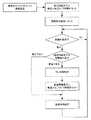
以下に、本発明に係わる部分の構成の詳細を説明する。また、図3に本発明に係る画像形成装置の制御動作の一例をフロー図で示す。
現像装置3には、現像装置内の現像剤のキャリアが新品であるかどうかの情報をもつ新品情報素子(図示せず)が備えられている。当然ながら初期状態として、新品情報素子には新品であるという情報がセットされている。また、中古現像装置に新品のキャリアをセットする場合も漏れなく新品情報素子に新品であるという情報をセットしなければならないということは言うまでもない。よって、できればこの作業を工場で行うことが望ましい。なお、新品情報素子としては、例えばICチップ等のメモリが用いられ、現像装置3のケース上等に設置されている。また、この新品情報素子は、現像装置3を画像形成装置に装着した際に、コネクタやケーブル等を介して画像形成装置の制御部(図示せず)に接続される。Below, the detail of the structure of the part concerning this invention is demonstrated. FIG. 3 is a flowchart showing an example of the control operation of the image forming apparatus according to the present invention.
The developing
次に、画像形成装置の制御部は、操作部(図示せず)からのキー入力等によって、画像作像指令が来たときに、新品情報素子の情報を読みにいく。なお、他の実施例としては、画像作像指令が来たときだけに限定せず、常時新品情報素子の情報を検知するというのでもよい。また、新品のキャリアが内蔵された現像装置3を画像形成装置に装着した直後の初期設定等の動作で、新品情報素子の情報を検知するというのでもよい。
そして、その新品情報素子の情報を読み込んだ結果、情報が新品ではないという情報ならば、制御部はそのまま印刷動作を行う。また、当然ながら、新品のキャリアが内蔵された現像装置を装着した直後の画像作像指令ならば、新品情報素子の情報から新品だと判断されるので、制御部は以下のプレ作像動作に入る。Next, the control unit of the image forming apparatus reads the information of the new information element when an image forming command is received by a key input or the like from an operation unit (not shown). In addition, as another Example, it may not be limited only when an image image formation command comes, but the information of a new information element may always be detected. Alternatively, the information of the new information element may be detected by an operation such as initial setting immediately after the developing
If the information of the new information element is read and the information is not new, the control unit performs the printing operation as it is. Of course, if it is an image imaging command immediately after installing a developing device incorporating a new carrier, it is determined that the product is new from the information of the new information element, so the control unit performs the following pre-imaging operation. enter.
ここで、プレ作像動作とは、記録媒体7を通さずに所定のハーフトーンパターンの作像動作を行うことであり、光学記録手段2によって感光体1に前記ハーフトーンパターン画像の潜像を形成し、それを現像装置3で現像するという動作である。これは、記録媒体7を通すと、その記録媒体が無駄になってしまうからである。また、記録媒体がないときにはエラーとなってしまい、ユーザーにとって面倒な作業となる。 Here, the pre-imaging operation is to perform an image forming operation of a predetermined halftone pattern without passing through the recording medium 7, and the latent image of the halftone pattern image is formed on the
プレ作像動作は一定時間継続して行われ、終了後には、制御部は新品情報素子の情報を、新品ではないという情報に書き換える。こうすることによって、次回からは新品だと検知されず、同一の現像装置に対して2度以上のプレ作像動作をさせないようにすることができる。 The pre-imaging operation is continuously performed for a certain period of time, and after the completion, the control unit rewrites information on the new information element with information indicating that it is not new. By doing so, it is not detected that it is new from the next time, and it is possible to prevent the same developing device from performing pre-imaging operation twice or more.
プレ作像動作の目的は、新品のキャリアに存在する、エッジ効果によるキャリア付着が発生しやすい、飽和磁化が小さいキャリア等を、強制的にキャリア付着させて除去することにある。したがって、できる限りキャリア付着を起こしやすい条件で行うことが、時間的効率や消費トナーの面からも好ましい。 The purpose of the pre-imaging operation is to forcibly attach and remove a carrier having a small saturation magnetization, which is likely to occur due to an edge effect and is present in a new carrier. Therefore, it is preferable from the viewpoint of time efficiency and toner consumption that the conditions are such that carrier adhesion is likely to occur.
プレ作像動作でハーフトーンパターンを出力するのは、非露光部と露光部との界面の総延長が長いからである。その結果、単位画像面積当たりの、エッジ効果によるキャリア付着が多くなり、効率がよくなる。理論的に、最も非露光部と露光部との界面の総延長が長くなるのは1ドットのチェッカー模様の50%パターンである。しかし、1ドットのみの潜像の場合、図4に示すように、露光による除電量が飽和しない場合が考えられ、その結果、有効なエッジ効果を得ることが出来なくなる。したがって、ハーフトーンの網点は2ドット以上で形成されるのが望ましい。なお、図4はあくまで一例であり、システムによって状況は変化するため、システムに応じて最適な網点のドット数を選べばよい。 The reason why the halftone pattern is output in the pre-imaging operation is that the total extension of the interface between the non-exposed portion and the exposed portion is long. As a result, the carrier adhesion due to the edge effect per unit image area increases, and the efficiency is improved. Theoretically, the total extension of the interface between the non-exposed portion and the exposed portion is the longest in a 50% pattern of 1-dot checker pattern. However, in the case of a latent image of only one dot, as shown in FIG. 4, there may be a case where the charge removal amount due to exposure is not saturated, and as a result, an effective edge effect cannot be obtained. Therefore, it is desirable that the halftone halftone dot be formed of 2 dots or more. Note that FIG. 4 is merely an example, and the situation changes depending on the system. Therefore, the optimum dot number of halftone dots may be selected according to the system.
また、50%以上のハーフトーンパターンを構成した場合、そのネガ画像は、非露光部と露光部との界面の総延長が同じままで50%以下の画像となる。よってネガ画像の方がトナー消費量を少なくできて、かつ同等のキャリア付着を得ることができる。ゆえに、ハーフトーンパターンは、50%以下の画像面積率とする。 When a halftone pattern of 50% or more is configured, the negative image becomes an image of 50% or less with the total extension of the interface between the non-exposed portion and the exposed portion remaining the same. Therefore, the negative image can reduce the amount of toner consumption and can obtain the same carrier adhesion. Therefore, the halftone pattern has an image area ratio of 50% or less.
先にも述べた通り、チェッカー模様のパターンが最も非露光部と露光部との界面の総延長が長くなるのだが、単位画像当たりのトナー消費とキャリア付着量のバランスでハーフトーンパターンの仕様を決めることが望ましい。その一例を図5、図6に示す。図5は4ドットのチェッカー模様のパターンであり、最も効率よくエッジ効果によるキャリア付着を発生させることができる。また、図6は4ドットの25%パターン(いわゆる4×4画像)であり、トナー消費量を少なくできる。 As mentioned earlier, the checker pattern has the longest total extension of the interface between the non-exposed area and the exposed area, but the halftone pattern specifications can be adjusted based on the balance between toner consumption per unit image and carrier adhesion amount. It is desirable to decide. An example is shown in FIGS. FIG. 5 shows a 4-dot checker pattern, which can generate carrier adhesion by the edge effect most efficiently. FIG. 6 shows a 4-dot 25% pattern (so-called 4 × 4 image), which can reduce the amount of toner consumption.
キャリア付着しやすい条件として、露光部と非露光部との電位差が大きいとき、すなわち感光体帯電電位が大きいときが挙げられる。この方が界面での電位差が大きくなり、エッジ効果が強くなるからである。
そこで、上記のプレ作像動作を行うときには、感光体帯電電位を、システムにおける許容最大値としている。As a condition for easy carrier adhesion, there is a case where the potential difference between the exposed portion and the non-exposed portion is large, that is, the case where the photosensitive member charging potential is large. This is because the potential difference at the interface becomes larger and the edge effect becomes stronger.
Therefore, when the pre-image forming operation is performed, the photosensitive member charging potential is set to the maximum allowable value in the system.
また、キャリア付着しやすい条件として、現像バイアスと感光体帯電電位との差が大きいときが挙げられる。この方が現像ローラからキャリアが離れやすくなるからである。
そこで、上記のプレ作像動作を行うときには、現像バイアスと感光体帯電電位との差を、通常の画像作像動作のときよりも大きいか或いは同等とする。当然ながら、その差を大きくしすぎると飽和磁化特性が規格内の正常なキャリアまで失うことになるので、適切な値にセットしなければならないのは言うまでもない。Further, as a condition that the carrier easily adheres, there is a case where the difference between the developing bias and the photosensitive member charging potential is large. This is because the carrier is more easily separated from the developing roller.
Therefore, when performing the pre-imaging operation described above, the difference between the developing bias and the photosensitive member charging potential is made larger or equal to that in the normal image imaging operation. Of course, if the difference is made too large, the saturation magnetization characteristic will be lost to the normal carrier within the standard, so it goes without saying that it must be set to an appropriate value.
プレ作像動作を継続させる時間については、特には定めない。ただし、短すぎる場合には十分にキャリア付着しやすいキャリアを除去することが出来ず、また、長すぎるとトナーを浪費するだけでなく、暴走していると勘違いさせる等、ユーザーに対して不信感を持たせることになる。よって適切な長さに設定されなければならないが、目安としては3分以内と考えられる。
もしそれで、十分にキャリアの除去が出来ていない場合は、その回避策の具体的な実施例として、強制プレ作像動作モードを設けてもよい。これはユーザーによって強制プレ動作を行うものであり、ユーザーがキャリア付着に対して不満足と判断したときに、操作部からのキー入力等によって行うように指示されるべきものである。The time for continuing the pre-imaging operation is not particularly defined. However, if it is too short, it will not be possible to remove the carrier that easily adheres to the carrier, and if it is too long, it will not only waste toner, but will also misunderstand that it is running out of control. Will be given. Therefore, although it must be set to an appropriate length, it is considered that it is within 3 minutes as a guide.
If the carrier has not been sufficiently removed, a forced pre-imaging operation mode may be provided as a specific example of the workaround. This is a forced pre-operation by the user, and should be instructed to be performed by a key input or the like from the operation unit when the user determines that the carrier adhesion is unsatisfactory.
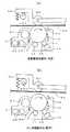
ところで、プレ作像動作は、記録媒体7を通さずに作像動作を行っているので、転写装置4をトナーで汚さないようにしなければならない。例えば、図1において、記録媒体7を通さずに作像を行った場合、第二転写部5に画像が転写されて汚れてしまい、次回に記録媒体7を通過させたときに、記録媒体7の裏側に汚れが転写される。
よって、それを回避する手法として、プレ作像動作を行うときには、感光体1と転写装置4とを離間させる手法と、転写バイアスを切る或いは逆バイアスをかけるという手法がある。転写バイアスとは、帯電したトナーを転写させるために電界をかけることで、通常は順方向に転写させるための電界をかける。しかし、転写バイアスを切る或いは逆バイアスをかけることによって、電界が転写させないか或いは逆方向への転写を促すようになるので、感光体上のトナー画像を転写させないようにすることができる。Incidentally, since the pre-imaging operation is performed without passing through the recording medium 7, the
Therefore, as a method for avoiding this, there are a method of separating the
まず、図1、図7を用いて離間する方法について述べる。図1、図7(a)の例では、中間転写体4−1に転写ベルト4−2を用いているので、主にカム4−4−1等により第一転写ローラ4−3と転写ベルト4−2を感光体1より離間させるための離間手段4−4を設け、図7(b)に示すように、転写ベルト4−2と感光体1とを離間する構成が取られているが、もちろん、第二転写部5に同様の離間手段を設けて転写ベルト4−2と第二転写部5とを離間させる構成としてもよい。双方とも効果は同じである。
また、転写装置に中間転写体4−1を用いずに、第二転写部5と同様の構成の転写部で感光体から記録媒体に直接転写する構成の場合においても同様で、感光体と転写部とを離間させる構成とすればよい。First, the separation method will be described with reference to FIGS. In the example of FIGS. 1 and 7A, since the transfer belt 4-2 is used as the intermediate transfer body 4-1, the first transfer roller 4-3 and the transfer belt are mainly driven by the cam 4-4-1 or the like. Although a separation means 4-4 for separating 4-2 from the
The same applies to the case where the transfer unit is configured to transfer directly from the photosensitive member to the recording medium by the transfer unit having the same configuration as the
次に転写バイアスを切る或いは逆バイアスをかけるという手法についても同様に考えればよい。中間転写体4−1を用いた例では、第一転写ローラ4−3と感光体1との間に印加される転写バイアスを切る或いは逆バイアスをかけることになるが、もちろん、第二転写ローラ4−5と第二転写部5間とで同様の手法を行ってもよい。双方とも効果は同じである。
また、転写装置に中間転写体4−1を用いずに、第二転写部5と同様の構成の転写部で感光体から記録媒体に直接転写する構成の場合においても同様で、感光体と転写部とのバイアスを切る或いは逆バイアスをかければよい。Next, the method of cutting the transfer bias or applying the reverse bias may be considered similarly. In the example using the intermediate transfer member 4-1, the transfer bias applied between the first transfer roller 4-3 and the
The same applies to the case where the transfer unit is configured to transfer directly from the photosensitive member to the recording medium by the transfer unit having the same configuration as the
1:感光体(像担持体)
1−1:帯電装置(帯電ローラ等)
1−2:クリーニング装置(トナークリーニングブレード等)
1−3:除電用LED
1−4:滑剤
1−5:滑剤塗布ローラ
2:光学記録手段
2−1:ポリゴンミラー
2−2:光源
3:現像装置
3−1:現像ローラ
3−2:攪拌ローラ
3−3:ドクタブレード
4:転写装置
4−1:中間転写体
4−2:転写ベルト
4−3:第一転写ローラ
4−4:離間手段
4−4−1:カム
4−4−2:支点
4−5:第二転写ローラ
4−6:ベルトクリーニング装置
5:第二転写部
6:定着装置
7:記録媒体1: Photoconductor (image carrier)
1-1: Charging device (charging roller, etc.)
1-2: Cleaning device (toner cleaning blade, etc.)
1-3: LED for static elimination
1-4: Lubricant 1-5: Lubricant application roller 2: Optical recording means 2-1: Polygon mirror 2-2: Light source 3: Development device 3-1: Development roller 3-2: Stirrer roller 3-3: Doctor blade 4: Transfer device 4-1: Intermediate transfer member 4-2: Transfer belt 4-3: First transfer roller 4-4: Separating means 4-4-1: Cam 4-4-2: Support point 4-5: First Two transfer rollers 4-6: Belt cleaning device 5: Second transfer unit 6: Fixing device 7: Recording medium
Claims (15)
Translated fromJapanese前記現像装置には、前記現像装置内のキャリアが新品であるかどうかの情報をもった新品情報素子が備えられ、前記新品情報素子より前記現像装置内のキャリアが新品であると判断された場合には、前記潜像形成手段により前記像担持体に所定のハーフトーンパターンの潜像を形成し、前記現像装置によって前記潜像をトナー画像とするプレ作像動作を一定時間継続して行うことを特徴とする画像形成装置。An image carrier, a latent image forming unit for forming a latent image on the image carrier, and a developer having both a toner and a carrier for forming a toner image on the image carrier on which the latent image is formed An image forming apparatus comprising: a developing device including: a transfer device that transfers a toner image on the image carrier to a recording medium or an intermediate transfer member;
The developing device is provided with a new information element having information on whether or not the carrier in the developing device is new, and the carrier in the developing device is determined to be new by the new information element For example, a latent image having a predetermined halftone pattern is formed on the image carrier by the latent image forming unit, and a pre-image forming operation using the latent image as a toner image is continuously performed for a predetermined time by the developing device. An image forming apparatus.
前記プレ作像動作を行うときには、前記記録媒体の搬送を行わないことを特徴とする画像形成装置。The image forming apparatus according to claim 1.
The image forming apparatus, wherein the recording medium is not transported when the pre-image forming operation is performed.
前記プレ作像動作を行うときには、前記像担持体の帯電電位を当該画像形成装置の許容最大値とすることを特徴とする画像形成装置。The image forming apparatus according to claim 1 or 2,
An image forming apparatus, wherein when performing the pre-image forming operation, the charging potential of the image carrier is set to an allowable maximum value of the image forming apparatus.
前記プレ作像動作を行うときには、現像バイアスと像担持体帯電電位との差を、通常の画像作像動作のときよりも大きいか或いは同等とすることを特徴とする画像形成装置。The image forming apparatus according to any one of claims 1 to 3,
An image forming apparatus characterized in that, when the pre-image forming operation is performed, a difference between the developing bias and the image carrier charging potential is greater than or equal to that in the normal image forming operation.
前記プレ作像動作を行うときには、前記像担持体と前記転写装置とを離間させることを特徴とする画像形成装置。The image forming apparatus according to claim 1,
An image forming apparatus that separates the image carrier and the transfer device when performing the pre-image forming operation.
前記プレ作像動作を行うときには、前記像担持体と前記転写装置とに印加される転写バイアスを切る或いは逆バイアスをかけることを特徴とする画像形成装置。The image forming apparatus according to any one of claims 1 to 5,
An image forming apparatus, wherein when performing the pre-image forming operation, a transfer bias applied to the image carrier and the transfer device is turned off or a reverse bias is applied.
前記新品情報素子の情報は、通常の画像作像動作の前に毎回検知されることを特徴とする画像形成装置。The image forming apparatus according to any one of claims 1 to 6,
The information of the new information element is detected every time before a normal image forming operation.
前記プレ作像動作を行った後には、該新品情報素子の情報を、新品ではないという情報に書き換えることを特徴とする画像形成装置。The image forming apparatus according to any one of claims 1 to 7,
An image forming apparatus, wherein after the pre-imaging operation is performed, the information of the new information element is rewritten to information that it is not new.
前記ハーフトーンパターンの網点のサイズは、少なくとも2画素以上の幅及び高さであることを特徴とする画像形成装置。The image forming apparatus according to claim 1,
The halftone dot has a halftone dot size of at least two pixels in width and height.
前記ハーフトーンパターンのトナー画像面積率は、50%以下であることを特徴とする画像形成装置。The image forming apparatus according to any one of claims 1 to 9,
2. An image forming apparatus according to claim 1, wherein a toner image area ratio of the halftone pattern is 50% or less.
前記像担持体は光を照射することによって潜像が形成される光導電性の感光体であり、前記潜像形成手段は画像情報に応じて前記感光体に光を照射して潜像を形成する光学記録手段であることを特徴とする画像形成装置。The image forming apparatus according to claim 1,
The image bearing member is a photoconductive photosensitive member that forms a latent image by irradiating light, and the latent image forming unit irradiates the photosensitive member with light according to image information to form a latent image. An image forming apparatus characterized by being an optical recording means.
Priority Applications (1)
| Application Number | Priority Date | Filing Date | Title |
|---|---|---|---|
| JP2005345754AJP2007148257A (en) | 2005-11-30 | 2005-11-30 | Image forming apparatus, printer, copying machine, facsimile machine, multifunction machine |
Applications Claiming Priority (1)
| Application Number | Priority Date | Filing Date | Title |
|---|---|---|---|
| JP2005345754AJP2007148257A (en) | 2005-11-30 | 2005-11-30 | Image forming apparatus, printer, copying machine, facsimile machine, multifunction machine |
Publications (1)
| Publication Number | Publication Date |
|---|---|
| JP2007148257Atrue JP2007148257A (en) | 2007-06-14 |
Family
ID=38209700
Family Applications (1)
| Application Number | Title | Priority Date | Filing Date |
|---|---|---|---|
| JP2005345754APendingJP2007148257A (en) | 2005-11-30 | 2005-11-30 | Image forming apparatus, printer, copying machine, facsimile machine, multifunction machine |
Country Status (1)
| Country | Link |
|---|---|
| JP (1) | JP2007148257A (en) |
Cited By (3)
| Publication number | Priority date | Publication date | Assignee | Title |
|---|---|---|---|---|
| JP2009150931A (en)* | 2007-12-18 | 2009-07-09 | Konica Minolta Business Technologies Inc | Image forming device |
| CN111344628A (en)* | 2017-09-15 | 2020-06-26 | 瑞尔D斯帕克有限责任公司 | Switchable directional display device |
| JP2020149004A (en)* | 2019-03-15 | 2020-09-17 | 株式会社リコー | Image forming device |
- 2005
- 2005-11-30JPJP2005345754Apatent/JP2007148257A/enactivePending
Cited By (4)
| Publication number | Priority date | Publication date | Assignee | Title |
|---|---|---|---|---|
| JP2009150931A (en)* | 2007-12-18 | 2009-07-09 | Konica Minolta Business Technologies Inc | Image forming device |
| CN111344628A (en)* | 2017-09-15 | 2020-06-26 | 瑞尔D斯帕克有限责任公司 | Switchable directional display device |
| CN111344628B (en)* | 2017-09-15 | 2022-11-04 | 瑞尔D斯帕克有限责任公司 | Switchable directional display device |
| JP2020149004A (en)* | 2019-03-15 | 2020-09-17 | 株式会社リコー | Image forming device |
Similar Documents
| Publication | Publication Date | Title |
|---|---|---|
| JP2001324873A (en) | Developing method, developing apparatus, and image forming apparatus | |
| JPH02244170A (en) | Image forming device | |
| US7920157B2 (en) | Image forming apparatus that controls an exposure amount intensity for forming a first image formed of an equal or smaller number of consecutive dots than a predetermined number in a predetermined direction is higher than an electric intensity for forming a second | |
| JP2005099142A (en) | Development device | |
| US20070071505A1 (en) | Hybrid development apparatus and development method therefor | |
| JP2007108623A (en) | Image forming apparatus | |
| JP2979352B2 (en) | Image forming method | |
| US7903990B2 (en) | Image forming apparatus having a controller that controls a potential | |
| JP2007148257A (en) | Image forming apparatus, printer, copying machine, facsimile machine, multifunction machine | |
| JP2002148916A (en) | Developing device | |
| US5459559A (en) | Magnetic brush developing method using a two-component developer | |
| EP0599296B1 (en) | Color image forming apparatus | |
| JP2010066473A (en) | Image forming device | |
| JP2007323025A (en) | Developing device and image forming apparatus | |
| JP2008310109A (en) | Image forming apparatus | |
| JP4077202B2 (en) | Image forming apparatus | |
| JP2000267430A (en) | Image forming method and apparatus | |
| JP3372880B2 (en) | Image forming device | |
| JP2006047885A (en) | Image forming apparatus | |
| JP2008049694A (en) | Image forming apparatus and image forming method | |
| JP2964493B2 (en) | Multicolor image forming device | |
| JP3160060B2 (en) | Multicolor image forming method and apparatus | |
| JPH07261547A (en) | Developing device | |
| JPH06242654A (en) | Image forming device | |
| JPH0980858A (en) | Image forming device |