JP2007144788A - Inkjet recording device - Google Patents
Inkjet recording deviceDownload PDFInfo
- Publication number
- JP2007144788A JP2007144788AJP2005342317AJP2005342317AJP2007144788AJP 2007144788 AJP2007144788 AJP 2007144788AJP 2005342317 AJP2005342317 AJP 2005342317AJP 2005342317 AJP2005342317 AJP 2005342317AJP 2007144788 AJP2007144788 AJP 2007144788A
- Authority
- JP
- Japan
- Prior art keywords
- recording
- discharge port
- ink
- recording head
- ejection
- Prior art date
- Legal status (The legal status is an assumption and is not a legal conclusion. Google has not performed a legal analysis and makes no representation as to the accuracy of the status listed.)
- Withdrawn
Links
Images


Landscapes
- Ink Jet (AREA)
Abstract
Translated fromJapaneseDescription
Translated fromJapanese本発明は、インクジェット記録装置およびインクジェット記録方法に関し、特に、高画質記録および高速記録のための構成に関するものである。 The present invention relates to an ink jet recording apparatus and an ink jet recording method, and more particularly to a configuration for high image quality recording and high speed recording.
インクジェット記録装置による記録媒体上への記録において、高速で印字したいとするユーザーのニーズは高まってきている。高速化を重視した印字を行う際には、高画質を実現するために用いられているマルチパス印字の際のパス数を減らすといった方法が有効である。ここで印字のパス数とは、1ラインを完成させるのに必要なキャリッジの走査回数のことである。 In recording on a recording medium by an ink jet recording apparatus, there is an increasing need for users who want to print at high speed. When printing with an emphasis on speeding up, a method of reducing the number of passes in multi-pass printing that is used to achieve high image quality is effective. Here, the number of printing passes is the number of times the carriage is scanned to complete one line.
これは、記録ヘッドの吐出口の数がある一定値である関係上、パス数が多いほど一回の紙送り量は小さくなり、逆にパス数を少なくするほど一回の紙送りの量を大きくすることができるからである。例えば、4パス印字が行われているところを2パスで印字することが可能であれば、単純には約2倍の高速化が図れることになる。1パス印字が可能となれば更に高速化が図れることは言うまでもない。すなわち、パス数が少なくなればなるほど所定領域(例えば、1枚)の記録に要するキャリッジのスキャン回数は減り、かつ、一回の紙送り量は大きくなり、結果的に1枚を印字するのにかかる時間は短くなる。 This is because the number of ejection ports of the recording head is a fixed value, so the larger the number of passes, the smaller the paper feed amount per one time. Conversely, the smaller the number of passes, the smaller the amount of paper feed per time. This is because it can be enlarged. For example, if it is possible to print a place where four passes are being printed in two passes, the speed can be increased approximately twice. Needless to say, if one-pass printing is possible, the speed can be further increased. In other words, the smaller the number of passes, the smaller the number of carriage scans required to record a predetermined area (for example, one sheet), and the larger the amount of paper feed that can be done, resulting in printing one sheet. Such time is shortened.
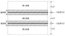
記録液(インク)を吐出する複数の吐出口を持つ記録ヘッドを、吐出口の配列方向とほぼ垂直な方向に走査して印字を行う関係上、1パスで印字を行う場合には、1度の走査により図1のように帯状の画像領域(バンド)が形成されることになる。 In order to perform printing by scanning a recording head having a plurality of ejection openings for ejecting recording liquid (ink) in a direction substantially perpendicular to the arrangement direction of the ejection openings, once printing is performed in one pass. By this scanning, a band-like image region (band) is formed as shown in FIG.
このように1パスで印字を行う際には、1バンドの領域を1度の走査で形成するため、1度に被記録媒体上へ打ち込む記録インクのデューティー(比率)が1バンドの領域を4回の走査で形成する4パス印字よりも約4倍多くなる。このため、記録液の性質により程度の差は異なるものの普通紙のようなドットがにじみやすい記録媒体ではバンド間のつなぎ部において黒いつなぎスジの発生が顕著なものとなり、印字品位を劣化させる。 In this way, when printing in one pass, since one band area is formed by one scan, four bands are formed in which the duty (ratio) of the recording ink that is driven onto the recording medium at one time is one band. This is about 4 times more than the 4-pass printing formed by one scan. For this reason, although the degree of difference varies depending on the properties of the recording liquid, in a recording medium such as plain paper in which dots are likely to blur, black connecting streaks are prominently generated at the connecting portion between bands, and print quality is deteriorated.
上述した問題点に対して、黒いつなぎスジをなくし、高画質化を図る方法が提案されている(例えば、特許文献1参照)。以下、従来のつなぎスジを緩和させる方法について説明する。 In order to solve the above-described problems, a method has been proposed in which black connecting stripes are eliminated and image quality is improved (see, for example, Patent Document 1). Hereinafter, a conventional method for reducing the connecting stripe will be described.
特許文献1には、シリアルスキャン方式において、記録ヘッドが主走査方向に繰り返し走査して1バンド分ずつ画像を記録するときに、その1バンド分ずつの記録領域のつなぎ目部分にスジを発生させないようにする方法が記載されている。すなわち、つなぎ部を形成する走査において、つなぎ部近傍領域のドットカウントに応じて前記領域で印字データの間引き処理を行うことで、黒いつなぎスジを解消するという方法である。 In Patent Document 1, in the serial scan method, when the recording head repeatedly scans in the main scanning direction and records an image for each band, a streak is not generated at the joint portion of the recording area for each band. The method of making is described. That is, in the scan for forming the joint portion, the black joint stripe is eliminated by performing the print data thinning process in the region in accordance with the dot count in the region near the joint portion.
また、特許文献2には、シリアルスキャン方式において、記録ヘッドが主走査方向に繰り返し走査して1バンド分ずつ画像を記録するときにつなぎスジを目立たなくさせ、つなぎ目の目立たない画像を得るための方法が記載されている。すなわち、1パス印字において、1走査により印刷する画像と次の走査により印刷する画像とを一部重複させて印刷し、その重複する領域をランダムマスクパターンによって両走査で補間するように印刷する方法である。 Japanese Patent Laid-Open No. 2004-228628 is for obtaining a non-conspicuous image by making a recording head inconspicuous when a recording head repeatedly scans in the main scanning direction and records an image for each band. A method is described. That is, in a one-pass printing, a method of printing an image printed by one scan and an image printed by the next scan partially overlapping, and printing such that the overlapping region is interpolated by both scans by a random mask pattern It is.
また、特許文献3には、シリアルスキャン方式のマルチパス印字において、紙送り量または使用するノズル群の領域を乱数的に設定することでつなぎスジの周期をランダム化し、つなぎスジを目立たなくするという方法が提案されている。
しかしながら従来の方法では、つなぎ部が常に黒スジとなる場合は適用できるものの、紙送り精度や端ヨレなどといった要因による白スジは解消することができなかった。端ヨレとは、端部吐出口の着弾位置がヘッド中央部に向かってよってしまうという現象であり、1回の走査で印字するデューティーが高いほど着弾位置のずれ量(端ヨレ量と呼ぶ)が大きいことが観察されている。この現象について図2を用いて説明する。図2は、印字デューティーが高い場合のインク滴の吐出状態を示している。印字デューティーが高い場合には、各吐出口に対応するすべての吐出エネルギー発生部(図示せず)が高い駆動周波数で駆動される。このため、吐出口からプリント媒体22に向けて吐出するインク滴23の運動に伴い、その周囲に介在する粘性を持った空気もインク滴3の運動に引きずられて移動する。この結果、記録ヘッド21の吐出口が開口する吐出口面24近傍が記録ヘッド21の周囲よりも減圧傾向となり、周囲の空気が減圧領域へ気流となって流れ、その流れの影響によって、特に吐出口の配列方向両端側に位置する吐出口から吐出されるインク滴23がその配列方向中央側に引き寄せられ、プリント媒体22に対して所期の位置に吐出されなくなることが判明した。このことから、端部の複数の吐出液滴が中央部へ引き寄せられている。例えば、端ヨレがなくインク滴が所望の着弾位置に着弾した場合は図3のようにつなぎ部がスジとなっていない。しかし、図4のようにインク滴がヘッド中央部に向かってよれて記録媒体に着弾すると、つなぎ部が白スジとなって視認されやすくなる。 However, although the conventional method can be applied when the connecting portion is always black stripes, white stripes due to factors such as paper feed accuracy and edge deviation cannot be eliminated. The end deviation is a phenomenon in which the landing position of the end discharge port is directed toward the center of the head. The higher the duty printed in one scan, the more the landing position shift amount (referred to as the end deflection amount). It has been observed to be large. This phenomenon will be described with reference to FIG. FIG. 2 shows an ink droplet ejection state when the printing duty is high. When the print duty is high, all the discharge energy generating units (not shown) corresponding to the respective discharge ports are driven at a high drive frequency. For this reason, along with the movement of the ink droplet 23 ejected from the ejection port toward the
また、記録ヘッドによってはヘッド中心部から外側に向かってインク滴が吐出する場合もあり、そういった場合はつなぎ部が黒スジとなってしまうことがある。つなぎスジは記録媒体によっても変化し、例えば普通紙のようなインクがにじみやすい記録媒体ではつなぎスジが黒スジになりやすい。 Also, depending on the recording head, ink droplets may be ejected outward from the center of the head, and in such a case, the connecting portion may become a black stripe. The connecting stripe also changes depending on the recording medium. For example, in a recording medium in which ink such as plain paper tends to bleed, the connecting stripe tends to become a black stripe.
1パス印字では、1度に被記録媒体上へ打ち込む記録インクのデューティーが4パスよりも大きいため端ヨレ量が4パス印字と比較して大きくなる。これによって、写真用紙のようにドットがにじみにくいような記録媒体に印字した場合、1パス印字では4パス印字に比べて端ヨレ量が大きいためつなぎスジがより一層白いスジとなり、画像品位を大きく劣化させる。更に、従来技術のように端ノズルを使用して印字データを補正する場合、端ヨレなどの影響によって所望の補正をすることが困難であり、つなぎスジを低減させる精度が十分とは言えず、印字された画像につなぎスジが目立つ場合があった。以上のような現象は小液滴化(4.5pl以下)・吐出口の高密度化(600dpi以上)に伴って特に顕著になり、写真やグラフィックのようなより高品位な画像を得るためには従来技術だけでは不十分であった。 In 1-pass printing, the duty of the recording ink that is struck onto the recording medium at a time is larger than 4 passes, so that the amount of edge deviation is larger than that in 4-pass printing. As a result, when printing on a recording medium such as photographic paper where dots do not easily bleed, 1-pass printing has a larger edge deviation than 4-pass printing, resulting in even more white stripes and higher image quality. Deteriorate. Furthermore, when correcting the print data using the end nozzle as in the prior art, it is difficult to make a desired correction due to the influence of the end twist and the like, and it cannot be said that the accuracy of reducing the connecting stripe is sufficient. In some cases, streaks appear in the printed image. The above phenomenon becomes particularly noticeable as the droplet size is reduced (4.5 pl or less) and the discharge port density is increased (600 dpi or more), in order to obtain a higher quality image such as a photograph or graphic. The prior art alone was not sufficient.
このような端ヨレに対しては吐出口の配列方向両端側に位置する吐出口から吐出されるインク滴の大きさを大きくし、すなわちインク滴の慣性質量を増大させることによって、この配列方向両端側に位置する吐出口から吐出されるインク滴の吐出軌跡の偏倚を抑制することも可能である。しかしながら、インク滴を大きくすることは、高精細かつ高階調の画像を形成する上での障害になる。さらに、プリント媒体に対するインク滴の浸透が遅れる上、プリント媒体の膨潤に伴ってプリント画像の劣化を招来する可能性が高い。 For such an end twist, by increasing the size of the ink droplets ejected from the ejection ports located at both ends in the arrangement direction of the ejection ports, that is, by increasing the inertial mass of the ink droplets, It is also possible to suppress deviation in the ejection trajectory of the ink droplets ejected from the ejection ports located on the side. However, enlarging the ink droplets is an obstacle to forming a high definition and high gradation image. Further, the penetration of ink droplets into the print medium is delayed, and there is a high possibility that the print image will be deteriorated as the print medium swells.
本発明は、上述した問題点を解消するためになされたものであり、その目的とするところはより少ないパス数による印字の場合でもつなぎスジの少ない、高品位の画像を得ることができるインクジェット記録装置、記録方法を提供することにある。 The present invention has been made in order to solve the above-described problems, and an object of the present invention is to perform ink jet recording capable of obtaining a high-quality image with fewer connecting stripes in the case of printing with a smaller number of passes. An apparatus and a recording method are provided.
本発明は上記目的を達成するために、インクを吐出する複数の吐出部を有する記録ヘッドを記録媒体に対して相対的に走査しつつインクを吐出させて記録媒体に記録を行うインクジェット記録装置において、前記記録媒体を前記記録ヘッドの走査方向とは異なる方向に移動させる紙送り手段と、前記記録ヘッドにおいて、画像の濃度に応じて非記録吐出部領域を異なるように設定する手段を具備したことを特徴とする。 In order to achieve the above object, the present invention provides an ink jet recording apparatus that performs recording on a recording medium by ejecting ink while scanning a recording head having a plurality of ejection units that eject ink relative to the recording medium. , Paper feeding means for moving the recording medium in a direction different from the scanning direction of the recording head, and means for setting the non-recording discharge area in the recording head differently according to the image density. It is characterized by.
上記構成によれば、画像の濃度に応じて使用するノズル数を変化させることで、少ないパス数の印字でもつなぎスジの目立たない高品位な画像が得られる。 According to the above configuration, by changing the number of nozzles used in accordance with the image density, a high-quality image with no noticeable stripes can be obtained by printing with a small number of passes.
以下、本発明の実施の形態を、複数の記録ヘッドを有するシリアルプリンタを例に説明する。 Hereinafter, embodiments of the present invention will be described by taking a serial printer having a plurality of recording heads as an example.
図5は本発明を適用したインクジェット記録装置の実施例の要部構成を示す模式的斜視図である。図5において、複数(3個)のヘッドカートリッジ1A,1B,1Cがキャリッジ502に交換可能に搭載されている。各カートリッジ1A〜1Cのそれぞれには、記録ヘッド部を駆動する信号を受けるためのコネクターが設けられている。なお以下の説明では上記記録手段1A〜1Cの全体または任意の1つを指す場合、単に記録手段(記録ヘッドまたはヘッドカートリッジ)1で示すことにする。 FIG. 5 is a schematic perspective view showing the main configuration of an embodiment of an ink jet recording apparatus to which the present invention is applied. In FIG. 5, a plurality (three) of head cartridges 1A, 1B, and 1C are mounted on a
上記複数の記録ヘッド1は、それぞれ異なる色のインクで記録するものであり、それらのインクタンク部には例えばシアン、マゼンタ、イエローなどの異なるインクが収納されている。各記録ヘッド1はキャリッジ502に位置決めして交換可能に搭載されており、キャリッジ502には、上記コネクターを介して各記録ヘッド1に駆動信号等を伝達するためのコネクターホルダー(電気接続部)が設けられている。 The plurality of recording heads 1 perform recording with different color inks, and different inks such as cyan, magenta, and yellow are stored in their ink tank portions. Each recording head 1 is mounted on the
キャリッジ502は、主走査方向で装置本体に設置されたガイドシャフト503に沿って移動方向に案内指示される。そしてキャリッジ502は、主走査モーター504により、モータプーリー505、従動プーリー506、及びタイミングベルト507を介して駆動され、その位置及び移動を制御される。用紙やプラスチック薄板等の記録材508は、2組の搬送ローラーの回転により記録ヘッド501の吐出口面と対向する位置(記録部)を通して搬送(紙送り)される。なお記録材508は、記録部において平坦な記録面を形成できるように、その裏面をプラテン(不図示)により支持されている。この場合、キャリッジ502に搭載された各カートリッジ1は、それらの吐出口面がキャリッジ502から下方へ突出して上記2組の搬送ローラー対の間で記録材508と平坦になるように保持されている。 The
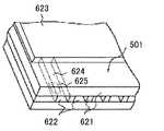
前記記録ヘッド1は、熱エネルギーを利用してインクを吐出するインクジェット記録手段であって、熱エネルギーを発生するための電気熱変換体を備えたものである。また前記記録ヘッド1は前記電気熱変換体によって印加される熱エネルギーにより生じる膜沸騰による気泡の成長、収縮によって生じる圧力変化を利用して、吐出口よりインクを吐出させ、記録を行うものである。本実施例に用いる複数のヘッドのノズル構成を図6に示す。 The recording head 1 is an ink jet recording unit that ejects ink using thermal energy, and includes an electrothermal transducer for generating thermal energy. The recording head 1 performs recording by ejecting ink from an ejection port by utilizing pressure changes caused by bubble growth and contraction caused by film boiling caused by thermal energy applied by the electrothermal transducer. . FIG. 6 shows the nozzle configuration of a plurality of heads used in this embodiment.
図6は、前記記録ヘッド1のインク吐出部513の主要部構造を部分的に示す模式的斜視図である。図6において記録材508と所定の隙間(約0.5〜2[mm]程度)をおいて対面する吐出口面621には、所定のピッチ(ここでは、1200dpi)で複数(ここでは、512)の吐出口622が形成され、共通液室623を各吐出口622とを連通する各流路624の壁面に沿ってインク吐出量のエネルギーを発生するために電気熱変換体(発熱抵抗体など)625が配設されている。本例においては、記録ヘッド1は前記吐出口がキャリッジ502の走査方向と交差する方向に並ぶような位置関係で、該キャリッジ502に搭載されている。こうして画像信号または吐出信号に基づいて対応する電気熱変換体625を駆動(通電)して、流路624内のインクを膜沸騰させ、その時に発生する圧力によって吐出口622からインクを吐出させる記録ヘッド1が構成されている。 FIG. 6 is a schematic perspective view partially showing the main part structure of the ink ejection part 513 of the recording head 1. In FIG. 6, a plurality of (here, 512)
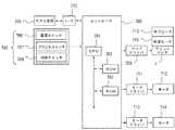
図7は、図5に示したインクジェットプリント装置における制御回路の概略構成例を示す。図7において、コントローラ700は主制御部であり、例えばマイクロ・コンピュータ形態のCPU701、プログラムや所要のテーブルその他の固定データを格納したROM702、画像データを展開する領域や作業用の領域等を設けたRAM703を有する。ホスト装置704は、画像データの供給源(プリントに係る画像等のデータの作成、処理等を行うコンピュータとする他、画像読み取り用のリーダ部等の形態であってもよい)である。画像データ、その他のコマンド、ステータス信号等は、インタフェース(I/F)112を介してコントローラ700と送受信される。 FIG. 7 shows a schematic configuration example of a control circuit in the ink jet printing apparatus shown in FIG. In FIG. 7, a
操作部705は操作者による指示入力を受容するスイッチ群であり、電源スイッチ706、プリント開始を指示するためのスイッチ707、吸引回復の起動を指示するための回復スイッチ708等を有する。 The
ヘッド・ドライバ709は、プリントデータ等に応じてプリント・ヘッド1の吐出ヒータ710を駆動するドライバである。ヘッド・ドライバ709は、プリントデータを吐出ヒータ710の位置に対応させて整列させるシフト・レジスタ、適宜のタイミングでラッチするラッチ回路、駆動タイミング信号に同期して吐出ヒータを作動させる論理回路素子の他、ドット形成位置合わせのために駆動タイミング(吐出タイミング)を適切に設定するタイミング設定部等を有する。 The
プリント・ヘッド1には、サブヒータ712が設けられている。サブヒータ712はインクの吐出特性を安定させるための温度調整を行うものであり、吐出ヒータ710と同時にプリント・ヘッド基板上に形成された形態および/またはプリント・ヘッド本体ないしはヘッド・カートリッジに取り付けられる形態とすることができる。 The print head 1 is provided with a sub-heater 712. The sub-heater 712 adjusts the temperature to stabilize the ink ejection characteristics, and is formed on the print head substrate at the same time as the
モータ・ドライバ711は主走査モータ712を駆動するドライバであり、副走査モータ714はプリント媒体508を搬送(副走査)するために用いられるモータであり、モータ・ドライバ713はそのドライバである。 The
上記構成装置を用いて以下に本発明での具体的な実施例を示す。 Specific examples of the present invention will be described below using the above-described configuration apparatus.
<1パス印字において、印字Dutyに応じて使用ノズルを変化させぴったりつなぐ。>
以下に第1実施例として、インクジェット記録装置を用いて、階調に応じて使用ノズルを変化させて画像を1パスで形成する例を、図面を用いて説明する。<In 1-pass printing, change the nozzle to be used according to the printing duty and connect it exactly. >
In the following, as an example of the first embodiment, an example in which an image is formed in one pass by changing the nozzles used in accordance with the gradation using an inkjet recording apparatus will be described with reference to the drawings.
図8は、本実施例に用いたインクジェット記録ヘッドである。この記録ヘッドは吐出口を512有し、各吐出口が2400dpi間隔で配列されていて、各吐出口から2.5plのインク滴を吐出する。記録ヘッドの上端部に位置する吐出口から吐出口1、吐出口2とし、吐出口512まで配列されているとする。この吐出口群のうち、吐出口1から吐出口3までを吐出口群1、吐出口4から吐出口509までを吐出口群2、吐出口510から吐出口512までを吐出口群3とする。図8に記載の記録ヘッドを用いて1パスで画像を形成する過程について図9を用いて説明する。図9は、紙送り量を走査毎に一定とし、その長さを吐出口群2と同一、すなわち5.34mmに設定して1パスで画像を形成している。第1走査では記録領域1を印字し、第2走査では記録領域2を印字する。よって、最大記録領域幅は紙送り量と同一長さとなる。1回の走査で印字するデューティーが高いと図4で示したように端ヨレが生じて実際に印字される記録領域幅が最大記録領域幅よりも短くなってしまう。図10は、図8に示す記録ヘッドの吐出口群2すなわち506ノズルを用いて印字した場合における、印字デューティーと端ヨレ量の関係を表す。印字デューティー100%とは、全吐出口から一斉にインク滴を吐出させたベタプリントに相当する。印字デューティーが6%の場合は端ヨレ量が約5μmとなるので、全吐出口(吐出口群2)を用いて印字すると実際に印字される記録領域幅は紙送り量5.34mmよりも10μm短い5.33mmとなる。この場合、印字デューティーが6%と低いためインク滴が分散されて配置されていること、端ヨレ量が5μmと小さいこと、から図9におけるつなぎ部のつなぎスジはほとんど視認されない。しかし、吐出口群2を用いてベタプリント(印字デューティー100%)を行なうと印字デューティー100%における端ヨレ量が30μmであることから実際に印字される記録幅は5.34mmよりも60μm短い5.28mmとなる。よって、つなぎ部に白いつなぎスジが現れ画像が大きく劣化する。そこで、印字デューティー100%の場合は使用する吐出口を吐出口群2だけでなく、吐出口群1および吐出口群3も用いて印字を行なう。これについて、図11を用いて説明する。吐出口群1、吐出口群2、吐出口群3を用いてベタプリントを行なうと、吐出口1および吐出口512は図10と同様に(使用する全吐出口数が512ノズルと506ノズルではほぼ同じ端ヨレ量である)それぞれ約30μmずつ記録ヘッド中心部に向かってよれて着弾する。すなわち、吐出口1から吐出されたインク滴はおよそ吐出口4の位置に着弾し、同様に吐出口512から吐出されたインク滴はおよそ吐出口509の位置に着弾することになる。よって、実際に印字される記録領域は図11の記録領域Aとなる。この方法によってつなぎ部のスジが目立たなくなり、ベタプリントを行なう際に最も画像劣化の要因となっていたつなぎスジを低減することができる。 FIG. 8 shows the ink jet recording head used in this example. This recording head has 512 ejection ports, and each ejection port is arranged at intervals of 2400 dpi, and ejects 2.5 pl ink droplets from each ejection port. Assume that the discharge ports 1 and 2 are arranged from the discharge port located at the upper end of the recording head to the
次に、各印字デューティーにおける全使用吐出口数を設定する手順を説明する。一つは、図10のように印字デューティーと端ヨレ量をあらかじめ測定によって求めておき、端ヨレ量によって吐出口群2以外に使用する吐出口を設定する。例えば、印字デューティー50%の場合は端ヨレ量が20μmなので吐出口群2以外に吐出口3および吐出口510を使用すれば所望の記録領域(図11記録領域A)が得られる。印字デューティー75%の場合は端ヨレ量が25μmであるが、このように端ヨレ量が吐出口間隔のおよそ整数倍でないときはつなぎスジが目立たないように使用する吐出口を設定すればよい。すなわち、吐出口群2と吐出口2、3および吐出口510、511を使用する場合と、吐出口群1と吐出口群2と吐出口群3の全てを使用する場合と、吐出口群1および吐出口群2、さらに吐出口510および吐出口511を使用する場合の3通りの設定方法があるが、いずれのうち最もつなぎスジが目立たない場合を選択すればよい。 Next, a procedure for setting the total number of used ejection ports at each printing duty will be described. First, as shown in FIG. 10, the print duty and the end deflection amount are obtained in advance by measurement, and discharge ports to be used other than the discharge port group 2 are set according to the end deflection amount. For example, when the print duty is 50%, the end deviation amount is 20 μm, and therefore, if the discharge port 3 and the
以上説明してきたように、記録ヘッドを走査して1パスで画像を形成する方法において、印字デューティーすなわち画像濃度によって使用する吐出口数を変化させることにより端ヨレによるつなぎ部の白スジが低減され、高画質を得ることができる。 As described above, in the method of forming an image in one pass by scanning the recording head, the white streaks at the joint portion due to the end twist are reduced by changing the number of ejection ports to be used according to the print duty, that is, the image density, High image quality can be obtained.
本実施例では、記録ヘッドに対して1列の吐出口列がある場合について説明したが、複数列吐出口列がある場合についても同様の効果を得ることができる。例えば吐出口列1列に対して1色のインク滴を吐出することができるとき、吐出口列4色を用いてシアン、マゼンタ、イエロー、ブラックを各列から吐出するとすると、インク滴の色毎に使用する端部の吐出口数を異ならせることも可能である。これによって、カラー印字時のつなぎスジを低減することができる。 In this embodiment, the case where there is one ejection port array with respect to the recording head has been described, but the same effect can be obtained even when there are a plurality of ejection port arrays. For example, when ink droplets of one color can be ejected to one ejection port array, and if cyan, magenta, yellow, and black are ejected from each column using four ejection port arrays, for each ink droplet color It is also possible to vary the number of outlets used at the end. As a result, it is possible to reduce connecting stripes during color printing.
また、本発明は1パス印字だけでなく、複数回の走査でひとつの記録領域の印字を完成するマルチパス記録方法においても適用できる。 Further, the present invention can be applied not only to one-pass printing but also to a multi-pass printing method that completes printing of one recording area by scanning a plurality of times.
<1パス印字において、印字Dutyに応じて使用ノズルを間引く>
次に第2実施例として、1パス印字における本発明の適用例を説明する。<In 1-pass printing, use nozzles are thinned out according to the print duty>
Next, as a second embodiment, an application example of the present invention in one-pass printing will be described.
上述のインクジェット記録装置および記録ヘッド(図8)を用いて2パスで画像を形成する過程を、図12を用いて説明する。記録ヘッドは吐出口を512ノズル有し、図8と同様に上端部吐出口から順番に吐出口1、吐出口2とする。紙送り量は記録ヘッドよりも6ノズル間隔分63.5μmだけ短くし、走査毎に吐出口6ノズル分がオーバーラップするように設定し、全吐出口512ノズルを用いて印字を行なう。低印字デューティーでは端ヨレがないため、記録領域3は重複して印字されることによって黒スジが発生し、画像を劣化させる。そこで、低印字デューティーでは記録領域3を第1走査または第2走査のいずれかによって印字されるようにする。例えば、第1走査では吐出口507、吐出口509、吐出口511を使用し、第2走査では吐出口2、吐出口4、吐出口6を使用して印字することにより記録領域3を形成することで印字の重複による黒スジをなくすことが可能である。または、各印字デューティーにおいてつなぎ部がぴったりつながるように、使用する吐出口を設定してもよい。具体的には、第1走査で吐出口510、吐出口511、吐出口512を使用し、第2走査で吐出口1、吐出口2、吐出口3を使用するように設定してもよい。印字デューティーが100%の場合、上述の図10と同様に端ヨレが30μmだとすると、第1走査と第2走査によってつなぎ部が白スジになることもなく、黒スジになることもなくつなぎスジが目立たないようになる。 A process of forming an image in two passes using the above-described ink jet recording apparatus and recording head (FIG. 8) will be described with reference to FIG. The recording head has 512 discharge ports, and the discharge ports 1 and 2 are sequentially formed from the upper end discharge port in the same manner as in FIG. The paper feed amount is 63.5 μm shorter than the recording head by the 6 nozzle interval, and is set so that the 6 ejection nozzles overlap each scan, and printing is performed using all 512 ejection nozzles. Since there is no edge deviation at a low printing duty, the recording area 3 is printed redundantly, resulting in black streaks and deterioration of the image. Therefore, at a low printing duty, the recording area 3 is printed by either the first scan or the second scan. For example, the recording area 3 is formed by printing using the
以上説明してきたように、低印字デューティーでも端部ノズルを使用するため突然のインク滴吐出による吐出不良が実施例1と比較して起こりにくくなる。 As described above, since the end nozzle is used even at a low printing duty, ejection failure due to sudden ink droplet ejection is less likely to occur than in the first embodiment.
また、本説明のような1パス印字だけでなく、上述のマルチパス記録にも本実施例を適用することが可能である。 In addition to the one-pass printing as described above, the present embodiment can be applied to the above-described multi-pass printing.
<つなぎヘッド構成に本発明を適用した例>
図13のような記録ヘッドを用いて1パス印字をする場合に、使用する吐出口を印字デューティーによって変化させる。本実施例で用いた記録ヘッドは、インク滴の吐出量が2.8pl、吐出口間隔が2400dpi、1つの吐出口列は吐出口512ノズルで形成されており、8ノズル分がそれぞれオーバーラップするように配置されている。これは、全吐出口を用いて印字デューティー100%のベタプリントを行った際につなぎ(白)スジが発生しないようにオーバーラップするノズル数を決定している。この記録ヘッドにおいて、実施例2で説明したように、端ヨレのない低印字デューティーではオーバーラップした8ノズルにおいて、吐出口列1または吐出口列2のどちらか一方の吐出口を用いて印字することでつなぎ部の黒スジは解消される。<Example in which the present invention is applied to a connecting head configuration>
When one-pass printing is performed using a recording head as shown in FIG. 13, the ejection port to be used is changed depending on the printing duty. The recording head used in this example has an ink droplet ejection amount of 2.8 pl, an ejection port interval of 2400 dpi, and one ejection port array is formed by 512 ejection ports, and the eight nozzles overlap each other. Are arranged as follows. This determines the number of overlapping nozzles so that no joint (white) streaks occur when solid printing is performed with a printing duty of 100% using all the ejection openings. In this recording head, as described in the second embodiment, printing is performed by using either one of the discharge port array 1 or the discharge port array 2 at the overlapping 8 nozzles at the low print duty without end deviation. This eliminates the black streaks in the joints.
以上説明したように本発明は記録ヘッドが複数吐出口列からなるつなぎチップにも適用することが可能である。 As described above, the present invention can also be applied to a connecting chip in which the recording head includes a plurality of ejection port arrays.
(その他)
本発明は、特にインクジェット記録方式の中でも熱エネルギーを利用する方式の記録ヘッド、記録装置に於いて、優れた効果をもたらすものである。(Other)
The present invention provides an excellent effect particularly in a recording head and a recording apparatus that use thermal energy among inkjet recording methods.
その代表的な構成や原理については、例えば、米国特許第4723129号明細書、同第4740796号明細書に開示されている基本的な原理を用いて行なうものが好ましい。この方式は所謂オンデマンド型、コンティニュアス型のいずれにも適用可能であるが、特に、オンデマンド型の場合には、液体(インク)が保持されているシートや液路に対応して配置されている電気熱変換体に、記録情報に対応していて核沸騰を越える急速な温度上昇を与える少なくとも一つの駆動信号を印加することによって、電気熱変換体に熱エネルギーを発生せしめ、記録ヘッドの熱作用面に膜沸騰させて、結果的にこの駆動信号に一対一対応し液体(インク)内の気泡を形成出来るので有効である。この気泡の成長,収縮により吐出用開口を介して液体(インク)を吐出させて、少なくとも一つの滴を形成する。この駆動信号をパルス形状とすると、即時適切に気泡の成長収縮が行なわれるので、特に応答性に優れた液体(インク)の吐出が達成でき、より好ましい。このパルス形状の駆動信号としては、米国特許第4463359号明細書、同第4345262号明細書に記載されているようなものが適している。尚、上記熱作用面の温度上昇率に関する発明の米国特許第4313124号明細書に記載されている条件を採用すると、更に優れた記録を行なうことができる。 As its typical configuration and principle, for example, those performed using the basic principle disclosed in US Pat. Nos. 4,723,129 and 4,740,796 are preferable. This method can be applied to both the so-called on-demand type and continuous type. In particular, in the case of the on-demand type, it is arranged corresponding to the sheet or liquid path holding the liquid (ink). By applying at least one drive signal corresponding to the recorded information and giving a rapid temperature rise exceeding the nucleate boiling to the electrothermal transducer, the thermal energy is generated in the electrothermal transducer, and the recording head This is effective because the film is boiled on the heat acting surface, and as a result, bubbles in the liquid (ink) can be formed in a one-to-one correspondence with the drive signal. By the growth and contraction of the bubbles, liquid (ink) is ejected through the ejection opening to form at least one droplet. It is more preferable that the drive signal has a pulse shape, since the bubble growth and contraction is performed immediately and appropriately, and thus it is possible to achieve discharge of liquid (ink) having particularly excellent responsiveness. As this pulse-shaped drive signal, those described in US Pat. Nos. 4,463,359 and 4,345,262 are suitable. Further excellent recording can be performed by employing the conditions described in US Pat. No. 4,313,124 of the invention relating to the temperature rise rate of the heat acting surface.
記録ヘッドの構成としては、上述の各明細書に開示されているような吐出口、液路、電気熱変換体の組み合わせ構成(直線状液流路又は直角液流路)の他に熱作用部が屈曲する領域に配置されている構成を開示する米国特許第4558333号明細書、米国特許第4459600号明細書を用いた構成も本発明に含まれるものである。加えて、複数の電気熱変換体に対して、共通するスリットを電気熱変換体の吐出部とする構成を開示する特開昭59−123670号公報や熱エネルギーの圧力波を吸収する開孔を吐出部に対応せる構成を開示する特開昭59−138461号公報に基づいた構成としても本発明は有効である。 As the configuration of the recording head, in addition to the combination configuration (linear liquid channel or right-angle liquid channel) of the discharge port, the liquid channel, and the electrothermal transducer as disclosed in each of the above-mentioned specifications, the heat acting part The configurations using US Pat. No. 4,558,333 and US Pat. No. 4,459,600, which disclose a configuration in which is disposed in a bending region, are also included in the present invention. In addition, for a plurality of electrothermal transducers, Japanese Patent Application Laid-Open No. 59-123670 that discloses a configuration in which a common slit is used as a discharge portion of the electrothermal transducer, or an aperture that absorbs pressure waves of thermal energy is provided. The present invention is also effective as a configuration based on Japanese Patent Application Laid-Open No. 59-138461 which discloses a configuration corresponding to the discharge unit.
さらに加えて、本発明インクジェット記録装置の形態としては、コンピュータ等の情報処理機器の画像出力端末として用いられるものの他、リーダ等と組合せた複写装置、さらには送受信機能を有するファクシミリ装置の形態を採るもの等であってもよい。 In addition, the ink jet recording apparatus according to the present invention may be used as an image output terminal of an information processing device such as a computer, a copying apparatus combined with a reader or the like, and a facsimile apparatus having a transmission / reception function. The thing etc. may be sufficient.
Claims (9)
Translated fromJapanese前記記録媒体を前記記録ヘッドの走査方向とは異なる方向に移動させる紙送り手段と、
前記記録ヘッドにおいて、画像の濃度に応じて非記録吐出部領域を異なるように設定する手段を具備したことを特徴とするインクジェット記録装置。In an inkjet recording apparatus that performs recording on a recording medium by ejecting ink while scanning a recording head having a plurality of ejection port arrays each having a plurality of ejection ports that eject ink, relative to the recording medium ,
Paper feeding means for moving the recording medium in a direction different from the scanning direction of the recording head;
An ink jet recording apparatus comprising: a means for setting the non-recording discharge area to be different according to the image density in the recording head.
を特徴とする請求項1に記載のインクジェット記録装置。The inkjet recording apparatus according to claim 1, wherein the recording head has a non-recording discharge area that is an end of the discharge port array.
を特徴とする請求項1に記載のインクジェット記録装置。The inkjet recording apparatus according to claim 1, wherein the recording head has a non-recording discharge area that varies depending on the discharge port array.
を特徴とする請求項1に記載のインクジェット記録装置。2. The ink jet recording apparatus according to claim 1, wherein the recording head has a non-recording discharge area that varies depending on a color of an ink droplet in the discharge port array.
各吐出口列のつなぎ部における吐出口群のうち、画像の濃度に応じて非記録吐出部領域を異なるように設定する手段を具備したことを特徴とするインクジェット記録装置。In an inkjet recording apparatus that performs printing using a recording head in which a plurality of ejection port arrays having a plurality of ejection units that eject ink are arranged in series in the sub-scanning direction,
An ink jet recording apparatus comprising: means for setting a non-recording discharge area to be different in accordance with an image density in a group of discharge openings in a connection portion of each discharge port array.
を特徴とする請求項6に記載のインクジェット記録装置。The ink jet recording apparatus according to claim 6, wherein the recording head has a non-recording discharge area that is an end of the discharge port array.
を特徴とする請求項6に記載のインクジェット記録装置。The inkjet recording apparatus according to claim 6, wherein the recording head has a non-recording discharge area that varies depending on a color of an ink droplet.
Priority Applications (1)
| Application Number | Priority Date | Filing Date | Title |
|---|---|---|---|
| JP2005342317AJP2007144788A (en) | 2005-11-28 | 2005-11-28 | Inkjet recording device |
Applications Claiming Priority (1)
| Application Number | Priority Date | Filing Date | Title |
|---|---|---|---|
| JP2005342317AJP2007144788A (en) | 2005-11-28 | 2005-11-28 | Inkjet recording device |
Publications (1)
| Publication Number | Publication Date |
|---|---|
| JP2007144788Atrue JP2007144788A (en) | 2007-06-14 |
Family
ID=38206770
Family Applications (1)
| Application Number | Title | Priority Date | Filing Date |
|---|---|---|---|
| JP2005342317AWithdrawnJP2007144788A (en) | 2005-11-28 | 2005-11-28 | Inkjet recording device |
Country Status (1)
| Country | Link |
|---|---|
| JP (1) | JP2007144788A (en) |
Cited By (8)
| Publication number | Priority date | Publication date | Assignee | Title |
|---|---|---|---|---|
| JP2009208263A (en)* | 2008-02-29 | 2009-09-17 | Canon Inc | Ink-jet recording device and ink-jet recording method |
| JP2009274233A (en)* | 2008-05-12 | 2009-11-26 | Seiko Epson Corp | Liquid ejecting apparatus |
| JP2010120222A (en)* | 2008-11-18 | 2010-06-03 | Ricoh Co Ltd | Image formation device, image forming method, and program |
| JP2014065276A (en)* | 2012-09-27 | 2014-04-17 | Toshiba Tec Corp | Image forming apparatus |
| JP2015189171A (en)* | 2014-03-28 | 2015-11-02 | キヤノン株式会社 | Recording apparatus, recording method, and program |
| EP3045317A1 (en)* | 2015-01-14 | 2016-07-20 | Seiko Epson Corporation | Recording apparatus and recording method |
| EP3045316A1 (en)* | 2015-01-14 | 2016-07-20 | Seiko Epson Corporation | Recording apparatus and recording method |
| JP2019018582A (en)* | 2018-11-07 | 2019-02-07 | ブラザー工業株式会社 | Inkjet printer |
- 2005
- 2005-11-28JPJP2005342317Apatent/JP2007144788A/ennot_activeWithdrawn
Cited By (8)
| Publication number | Priority date | Publication date | Assignee | Title |
|---|---|---|---|---|
| JP2009208263A (en)* | 2008-02-29 | 2009-09-17 | Canon Inc | Ink-jet recording device and ink-jet recording method |
| JP2009274233A (en)* | 2008-05-12 | 2009-11-26 | Seiko Epson Corp | Liquid ejecting apparatus |
| JP2010120222A (en)* | 2008-11-18 | 2010-06-03 | Ricoh Co Ltd | Image formation device, image forming method, and program |
| JP2014065276A (en)* | 2012-09-27 | 2014-04-17 | Toshiba Tec Corp | Image forming apparatus |
| JP2015189171A (en)* | 2014-03-28 | 2015-11-02 | キヤノン株式会社 | Recording apparatus, recording method, and program |
| EP3045317A1 (en)* | 2015-01-14 | 2016-07-20 | Seiko Epson Corporation | Recording apparatus and recording method |
| EP3045316A1 (en)* | 2015-01-14 | 2016-07-20 | Seiko Epson Corporation | Recording apparatus and recording method |
| JP2019018582A (en)* | 2018-11-07 | 2019-02-07 | ブラザー工業株式会社 | Inkjet printer |
Similar Documents
| Publication | Publication Date | Title |
|---|---|---|
| JP5105777B2 (en) | Image processing method and inkjet recording apparatus | |
| US6669331B2 (en) | Ink jet print apparatus, ink jet printing method, program, and computer-readable storage medium that stores the program | |
| JP4182123B2 (en) | Inkjet recording head and inkjet recording apparatus | |
| JP4926680B2 (en) | Inkjet recording device | |
| JP4693343B2 (en) | Recording position adjusting method and ink jet recording apparatus | |
| JP5247006B2 (en) | Inkjet recording apparatus and inkjet recording method | |
| JP4217651B2 (en) | Inkjet recording device | |
| US7798604B2 (en) | Inkjet printer and inkjet printing method | |
| JP3884993B2 (en) | Image recording apparatus and image recording method | |
| JP2001018376A (en) | Recording device and recording method | |
| JP4913939B2 (en) | Inkjet recording apparatus and inkjet recording method | |
| JP3639703B2 (en) | Inkjet recording apparatus and inkjet recording method | |
| JP3155832B2 (en) | Ink jet recording method and recording apparatus | |
| JP4027135B2 (en) | Inkjet recording device | |
| JP5224968B2 (en) | Inkjet recording apparatus and inkjet recording method | |
| JP2007144788A (en) | Inkjet recording device | |
| US7806512B2 (en) | Ink jet printing apparatus and ink jet printing method | |
| JP4280400B2 (en) | Inkjet recording method, recording apparatus, and data processing method | |
| US8177328B2 (en) | Ink jet printing apparatus and ink jet printing method | |
| JP5065460B2 (en) | Recording position adjusting method and ink jet recording apparatus | |
| JP3907685B2 (en) | Image forming apparatus | |
| JP2875641B2 (en) | Inkjet recording method | |
| EP0897804A2 (en) | Liquid ink printhead | |
| JP2006103053A (en) | Recording apparatus, color complementary recording method, and ink jet recording head | |
| JP4262246B2 (en) | Image recording apparatus and control method thereof |
Legal Events
| Date | Code | Title | Description |
|---|---|---|---|
| A300 | Withdrawal of application because of no request for examination | Free format text:JAPANESE INTERMEDIATE CODE: A300 Effective date:20090203 |